EP1523810B1 - Scaling using gain factors for use in data detection for wireless code division multiple access communication systems - Google Patents
Scaling using gain factors for use in data detection for wireless code division multiple access communication systems Download PDFInfo
- Publication number
- EP1523810B1 EP1523810B1 EP03794437A EP03794437A EP1523810B1 EP 1523810 B1 EP1523810 B1 EP 1523810B1 EP 03794437 A EP03794437 A EP 03794437A EP 03794437 A EP03794437 A EP 03794437A EP 1523810 B1 EP1523810 B1 EP 1523810B1
- Authority
- EP
- European Patent Office
- Prior art keywords
- communications
- scaling
- factor
- data
- received communications
- Prior art date
- Legal status (The legal status is an assumption and is not a legal conclusion. Google has not performed a legal analysis and makes no representation as to the accuracy of the status listed.)
- Expired - Lifetime
Links
- 238000001514 detection method Methods 0.000 title claims description 25
- 238000000034 method Methods 0.000 claims description 12
- 238000001228 spectrum Methods 0.000 claims description 8
- 239000002131 composite material Substances 0.000 claims description 4
- 239000011159 matrix material Substances 0.000 description 35
- 238000013459 approach Methods 0.000 description 10
- 238000010586 diagram Methods 0.000 description 7
- 230000005540 biological transmission Effects 0.000 description 4
- 238000005070 sampling Methods 0.000 description 4
- 230000003044 adaptive effect Effects 0.000 description 2
- 238000009795 derivation Methods 0.000 description 2
- 108010003272 Hyaluronate lyase Proteins 0.000 description 1
- 230000003247 decreasing effect Effects 0.000 description 1
- 230000000694 effects Effects 0.000 description 1
- 230000010363 phase shift Effects 0.000 description 1
- 230000001360 synchronised effect Effects 0.000 description 1
Images


Classifications
-
- H—ELECTRICITY
- H04—ELECTRIC COMMUNICATION TECHNIQUE
- H04B—TRANSMISSION
- H04B1/00—Details of transmission systems, not covered by a single one of groups H04B3/00 - H04B13/00; Details of transmission systems not characterised by the medium used for transmission
- H04B1/69—Spread spectrum techniques
- H04B1/707—Spread spectrum techniques using direct sequence modulation
- H04B1/7097—Interference-related aspects
- H04B1/7103—Interference-related aspects the interference being multiple access interference
- H04B1/7105—Joint detection techniques, e.g. linear detectors
- H04B1/71055—Joint detection techniques, e.g. linear detectors using minimum mean squared error [MMSE] detector
-
- H—ELECTRICITY
- H04—ELECTRIC COMMUNICATION TECHNIQUE
- H04B—TRANSMISSION
- H04B1/00—Details of transmission systems, not covered by a single one of groups H04B3/00 - H04B13/00; Details of transmission systems not characterised by the medium used for transmission
- H04B1/06—Receivers
- H04B1/10—Means associated with receiver for limiting or suppressing noise or interference
- H04B1/1027—Means associated with receiver for limiting or suppressing noise or interference assessing signal quality or detecting noise/interference for the received signal
-
- H—ELECTRICITY
- H04—ELECTRIC COMMUNICATION TECHNIQUE
- H04B—TRANSMISSION
- H04B1/00—Details of transmission systems, not covered by a single one of groups H04B3/00 - H04B13/00; Details of transmission systems not characterised by the medium used for transmission
- H04B1/69—Spread spectrum techniques
- H04B1/707—Spread spectrum techniques using direct sequence modulation
- H04B1/7097—Interference-related aspects
- H04B1/7103—Interference-related aspects the interference being multiple access interference
-
- H—ELECTRICITY
- H04—ELECTRIC COMMUNICATION TECHNIQUE
- H04B—TRANSMISSION
- H04B7/00—Radio transmission systems, i.e. using radiation field
- H04B7/14—Relay systems
- H04B7/15—Active relay systems
- H04B7/155—Ground-based stations
-
- H—ELECTRICITY
- H04—ELECTRIC COMMUNICATION TECHNIQUE
- H04L—TRANSMISSION OF DIGITAL INFORMATION, e.g. TELEGRAPHIC COMMUNICATION
- H04L25/00—Baseband systems
- H04L25/02—Details ; arrangements for supplying electrical power along data transmission lines
- H04L25/0202—Channel estimation
- H04L25/0204—Channel estimation of multiple channels
-
- H—ELECTRICITY
- H04—ELECTRIC COMMUNICATION TECHNIQUE
- H04L—TRANSMISSION OF DIGITAL INFORMATION, e.g. TELEGRAPHIC COMMUNICATION
- H04L25/00—Baseband systems
- H04L25/02—Details ; arrangements for supplying electrical power along data transmission lines
- H04L25/0202—Channel estimation
- H04L25/0212—Channel estimation of impulse response
-
- H—ELECTRICITY
- H04—ELECTRIC COMMUNICATION TECHNIQUE
- H04L—TRANSMISSION OF DIGITAL INFORMATION, e.g. TELEGRAPHIC COMMUNICATION
- H04L25/00—Baseband systems
- H04L25/02—Details ; arrangements for supplying electrical power along data transmission lines
- H04L25/0202—Channel estimation
- H04L25/0224—Channel estimation using sounding signals
-
- H—ELECTRICITY
- H04—ELECTRIC COMMUNICATION TECHNIQUE
- H04L—TRANSMISSION OF DIGITAL INFORMATION, e.g. TELEGRAPHIC COMMUNICATION
- H04L25/00—Baseband systems
- H04L25/02—Details ; arrangements for supplying electrical power along data transmission lines
- H04L25/03—Shaping networks in transmitter or receiver, e.g. adaptive shaping networks
- H04L25/03006—Arrangements for removing intersymbol interference
-
- H—ELECTRICITY
- H04—ELECTRIC COMMUNICATION TECHNIQUE
- H04L—TRANSMISSION OF DIGITAL INFORMATION, e.g. TELEGRAPHIC COMMUNICATION
- H04L25/00—Baseband systems
- H04L25/02—Details ; arrangements for supplying electrical power along data transmission lines
- H04L25/0202—Channel estimation
Definitions
- This invention generally relates to wireless code division multiple access (CDMA) communication systems.
- the invention relates to scaling using gain factors during data detection in such systems.
- FDD frequency division duplex
- TDD time division duplex
- TD-SCDMA time division synchronous code division multiple access
- SUD single user detection
- the received signal is equalized to compensate for the response of the wireless channel.
- the equalized signal is despread using the codes of the user or users.
- SUD is typically utilized when all communications experience a same channel response.
- the preferred uses for the SUD is in the downlink and in the uplink when a single user monopolizes a frequency spectrum (in FDD) or time slot (in TDD or TD-SCDMA).
- Another approach to receive communications in such systems is referred to as multi-user detection (MUD).
- MUD the data from all users data is estimated simultaneously.
- the individual communications, transmitted simultaneously, may have varying transmission power levels.
- a single User Equipment may transmit multiple coded composite transport channels (CCTrCHs).
- CCTrCH may have a differing quality of service (QOS), requiring a different transmit power level to reach the required QOS.
- QOS quality of service
- each UE in addition to each individual UE's CCTrCH may require a differing transmission power level.
- US-B1-6175588 describes a communication device in a spread spectrum communication system.
- the communication device comprises an adaptive equalizer and a pilot channel demodulator, which produces a pilot channel estimate. Based on the pilot channel estimate, an error signal is generated which is used to control the adaptive equalizer.
- Data from a plurality of communications is transmitted in a code division multiple access communication system.
- the transmitted communications are received.
- Gain factors are determined for at least one of the received communications.
- Data of the received communications is detected using a scaling factor derived from the determined gain values.
- Figure 1A is a simplified diagram of a transmitter and a receiver using gain factor scaling for the uplink.
- Figure 1B is a simplified diagram of a transmitter and a receiver using gain factor scaling for the downlink.
- Figure 1C is a simplified diagram of channel response matrix scaling.
- Figure 2 is a flow chart for applying selective code power scaling.
- Figure 3 is a flow chart for applying total power scaling.
- Figure 4 is a flow chart for iterative selective code power scaling.
- Figure 5A is a simplified block diagram of a multiuser detection receiver using a scaled noise variance.
- Figure 5B is a simplified block diagram of a multiuser detection receiver using a scaled channel response matrix.
- Figures 1A , for the uplink, and 1B, for the downlink, are simplified diagrams of a transmitter and a receiver using gain factor scaling in a UE and base station.
- data is spread by a modulation and spreading device 24 using the appropriate codes and modulated, such as by using quadrature phase shift keying (QPSK), M-ary quadrature amplitude modulation (QAM) or other modulation scheme.
- QPSK quadrature phase shift keying
- QAM M-ary quadrature amplitude modulation
- the spread signal is modulated to radio frequency by a modulation device 26 and radiated by an antenna 28 or antenna array.
- an antenna 32 or antenna array at the base station 22 receives the communications.
- the received communications are converted to a baseband signal, such as by a demodulation device 34.
- a sampling device 36 samples the baseband signal, such as at the chip rate or a multiple of the chip rate, to produce a received vector r .
- a channel estimation device 38 estimates the channel responses for the received communications, as a channel response matrix H. All of the H matrixes in the following equations are presumed to be normalized.
- the channel estimation is typically performed using a reference signal, such as the midambles of communication bursts or a pilot code.
- the channel estimation device 38 also preferably estimates a variance of the noise ⁇ 2 , although the estimated noise variance may be derived from other sources.
- the noise variance a is scaled by a scaling device, such as by a factor of 1/P. Preferred derivations for the value of P are explained in detail later.
- the preferred embodiment scales the noise variance ⁇ 2
- the channel response matrix H may be scaled by a scaling device 61 instead of the noise variance, producing H', as shown in Figure 1C .
- a channel equalizer 42 uses the channel response matrix H and the scaled noise variance ⁇ 2 /P to produce a spread data vector s .
- the spread data vector s is scaled by a scaling device 44, such as by a factor 1/P ⁇ H , although this scaling device 44 may not be used.
- ( ⁇ ) H is the conjugate transpose operation.
- the despreader 46 despreads the scaled spread data or spread data using the codes C of the communications to recover the data d .
- data is spread and modulated by multiple modulation and spreading devices 48 1 to 48 N for transmission to one or multiple UEs 20.
- the spread signals are combined by a combiner 50 and modulated to radio frequency by a modulator 52.
- the modulated signal is radiated by an antenna 32 or antenna array.
- an antenna 28 or antenna array receives the communications sent through the wireless air interface 30.
- the received communications are demodulated by a demodulator 54 to baseband.
- a sampling device 56 samples the baseband signal to produce a received vector r .
- a channel estimation device 58 estimates the channel response matrix H and the noise variance ⁇ 2 .
- the noise variance is scaled by a scaling device 60, such as by a factor of 1/P. Alternately, as shown in Figure 1C , the channel response matrix H can be scaled.
- a channel equalizer 62 processes the samples using the channel response matrix H and scaled noise variance to produce a spread data vector s .
- the spread data vector s is scaled by a scaling device 64, such as by a factor 1/P ⁇ H , although scaling device 64 may not be used.
- the scaling device 64 is not used, the spread data vector s is passed directly to the despreader 66.
- the despreader 66 despreads either the scaled or unscaled spread data using the codes C of that UE's communications to recover the data of the UE's communications. Typically, if some of the received communications are for other UEs 20, the codes of those communications are not used to despread the other UEs' data.
- WCDMA wideband CDMA
- TD-SCDMA TD-SCDMA
- CDMA 2000 as well as others.
- the received vector r can be modeled per Equation 1.
- r ⁇ A ⁇ ⁇ d ⁇ + n ⁇
- A is the normalized symbol response matrix.
- ⁇ is the signal amplitude gain matrix and is a diagonal matrix, n is the noise vector.
- A [A 1 ,..., A K ] is the normalized symbol response matrix of the K codes.
- ⁇ is preferably of size K ⁇ N s ⁇ N s is the number of data symbols in a data field.
- d [ d 1 ,..., d K ] is the data sequence carried by the K codes.
- ⁇ is per Equation 2.
- ⁇ ⁇ 1 ⁇ 2 ⁇ ⁇ K
- Each amplitude gain sub-matrix for a k th code of the K codes, ⁇ k is a diagonal matrix of size of N s with all the diagonals equal to the signal amplitudes, g k , of the k th code, per Equation 3.
- ⁇ k g k 0 g k ⁇ 0 g k
- Equation 4 and 5 To estimate data d ⁇ in joint detection, a minimum mean square error (MMSE) approach per Equation 4 and 5 may be used.
- MMSE minimum mean square error
- H is preferably of size Q ⁇ N s + W - 1 by Q ⁇ N s .
- N s is the number of data symbols per data block that the data detection is performed.
- Q is the spreading factor of the communications and W is the length of the delay spread.
- C is preferably of size Q ⁇ N s by K ⁇ N s .
- the received signal for a common channel can be modeled per Equation 7.
- r ⁇ HC ⁇ ⁇ d ⁇ + n ⁇
- the matrix M is the code correlation matrix per Equation 9.
- M CG ⁇ C H
- M is preferably of size Q ⁇ N s .
- the code correlation matrix M is a diagonal dominant matrix with all the diagonals having a same value, such as P.
- One value for P is the total power of all bursts per Equation 11.
- M ⁇ P ⁇ I
- Equation 13 By substituting Equation 12 into Equation 8, Equation 13 or 14 results.
- d ⁇ ⁇ 1 P ⁇ ⁇ H ⁇ C H ⁇ H H ⁇ H ⁇ H H + ⁇ 2 P ⁇ I - 1 ⁇ r ⁇
- d ⁇ ⁇ 1 P ⁇ ⁇ H ⁇ C H ⁇ H H ⁇ H + ⁇ 2 P ⁇ I - 1 ⁇ H H ⁇ r ⁇ Equation 13 and 14 are interchangeable by the matrix inversion lemma.
- Equation 14 can be broken down in two stages per Equations 15 and 16.
- Equation 15 the channel equalization is performed.
- the scaling in Equation 15 is performed by scaling devices 40, 60.
- an approximate Cholesky or fast Fourier transform based solution is used, although other techniques may be used.
- the despreading is performed.
- the scaling, 1 P ⁇ ⁇ H , during or prior to despreading may or may not be performed. Such scaling tends to improve the decoding performance of turbo-encoded signals.
- I f the residual interference after equalization due to the incomplete equalization of channel distortion that results in the inter-symbol interference (ISI) and multiple access interference (MAI).
- ⁇ est of Equation 18 represents the impact of I f on the estimated spread data.
- w represents the noise after equalization and is per Equation 19.
- w ⁇ H H ⁇ H + ⁇ 2 P ⁇ I - 1 ⁇ H H ⁇ n ⁇
- the interference I f and noise w cannot be reduced simultaneously. Decreasing one tends to increase the other. For a large P, the residual interference is reduced, but the noise is increased. For a small P, the noise is reduced but at the cost of increased residual interference.
- M is the number of UEs and N is the number of CCTrCHs per UE.
- K m,n is the total number of codes in the n th CCTrCH of the m th UE and g m,n is the gain factor for the n th CCTrCH of the m th UE.
- G ⁇ 1 , 1 2 ⁇ ⁇ 1 , N 2 ⁇ ⁇ ⁇ M , 1 2 ⁇ ⁇ M , N 2
- ⁇ m , n 2 is the code power sub-matrix corresponding to the n th CCTrCH of the m th UE.
- the code power g m , n 2 in the matrix G and in G's sub-matrix can be approximated by one single common power in a least square error approach by minimizing Equation 22.
- x lse arg min x ⁇ m , n M , N x - g m , n 2 2
- the solution of least-square-error-power is the average power of all codes per Equation 23.
- K is the total number of codes transmitted in the time period of interest for the system and is per Equation 24.
- Equation 25 The code power scale factor is determined by Equation 25.
- g avg 2 is the average code power.
- total power scaling is optimal over all connections by minimizing the code power mismatch over all connections.
- Equation 27 P is a factor for the j th UE that is based on the interference and noise level.
- ⁇ j should be adaptively adjusted based on the interference and noise level for optimum performance of the data detection.
- Two preferred equations for deriving ⁇ j are per Equations 28 and 29.
- K i,j is the number of codes for the i th CCTrCH of the j th UE.
- g i,j is the gain factor for the i th CCTrCH for the j th UE.
- I is the number of CCTrCHs of the UE.
- Selective code power scaling may also be used to optimize a particular CCTrCH of a UE.
- Equation 30 To optimize the i th CCTrCH of the j th UE, Equation 30 is used.
- P ⁇ i , j ⁇ P T ⁇ i,j is a factor for the i th CCTrCH of the j th UE.
- Selective code power scaling may also be used to optimize a particular code of a particular CCTrCH of a UE.
- ⁇ n,i,j is a factor for the n th code of the i th CCTrCH of the j th UE.
- Two preferred equations for determining ⁇ n,i,j are Equations 32 and 33.
- maximum code power scaling the maximum code power is used for the scaling.
- Maximum code power scaling is most applicable when the over-scaling of code power degrades less than the under-scaling of code power.
- minimum code power scaling the minimum code power is used for scaling. Minimum code power scaling is most applicable when the under-scaling of code power degrades less than the over-scaling of code power.
- FIG. 2 is one flow chart for applying code power scaling.
- One UE or UE's CCTrCH is selected for optimum performance, Step 70. If SUD is being performed at the UE the selected CCTrCH is typically with the highest required QOS. If SUD is being performed at the base station, the UE of interest may be the farthest UE, to reduce that UE's transmission power level. Alternatively, the UE or UE CCTrCH of interest may be the UE or UE CCTrCH requiring the highest quality of service.
- the gain factor(s) for that UE/CCTrCH is determined, Step 72.
- the code scaling factor P is determined from the gain factor(s). SUD is performed using the determined P, Step 74.
- the code scaling factor P is used in the data detection, such as by scaling devices 40, 44, 60, 64, Step 76. As a result, that UE's/LTE CCTrCH's performance is optimized.
- FIG. 3 is a flow chart for total power scaling.
- Total power scaling is preferably performed if all the CCTrCHs at a UE or base station require the same QOS. Additionally, total power scaling may be applied to reduce the complexity by eliminating the need to optimize the SUD for a particular UE.
- the gain factors of all UE codes are determined, Step 78, and the resulting code scaling factor P is determined, Step 80.
- the SUD is performed using the determined P, Step 82. This approach equally optimizes all codes.
- P is not necessarily determined from the gain factors.
- gain scaling is not required and steps 78 and 80 of Figure 3 in this situation can be avoided.
- FIG 4 is a flow chart of iterative selective code power scaling.
- each UE or UE CCTrCH can be optimized. Sequentially for each UE/UE CCTrCH, the gain factor(s) are determined and the resulting code scaling factor P is determined, Step 86. Using P, SUD is performed and the data for that UE/UE CCTrCH is estimated, Step 88. The process is repeated until each of the UEs/LTE CCTrCHs have been processed or all the UEs/UE CCTrCHs of interest have been processed, Step 90. This approach optimizes overall performance for each UE/LTE CCTrCH at the expense of added complexity and delay.
- FIGS. 5A and 5B are simplified block diagrams of gain factor scaling used in a multiuser detection receiver.
- multiuser detection data from all codes is detected simultaneously. These approaches to data detection can also experience improved performance by using gain factor scaling.
- the received communications are received by an antenna 100 or antenna array.
- the received communications are demodulated to baseband by a demodulator 102.
- the baseband signal is sampled by a sampling device 104 to produce a received vector, r .
- a channel estimation device 106 estimates the channel response as a channel response matrix, H.
- the noise variance ⁇ 2 is also determined, such as by the channel estimation device 106 or by another device.
- the noise variance ⁇ 2 is scaled by a scaling device 110, such as by a value 1/P.
- the channel response matrix H and the noise variance ⁇ 2 as well as the received vector and spreading codes C are input into a multiuser detection device 108.
- the multiuser detection device 108 produces a data vector d .
- the channel response matrix H is scaled.
- the received communications are received by an antenna 112 or antenna array.
- the received communications are demodulated to baseband by a demodulator 114.
- the baseband signal is sampled by a sampling device 116 to produce a received vector, r .
- a channel estimation device 118 estimates the channel response as a channel response matrix, H.
- the noise variance ⁇ 2 is also determined, such as by the channel estimation device 118 or by another device.
- the channel response matrix H is scaled by a scaling device 122, such as by a value P .
- the channel response matrix H and the noise variance ⁇ 2 as well as the received vector r and spreading codes C are input into a multiuser detection device 120.
- the multiuser detection device 120 produces a data vector d .
- P is derived using total power scaling.
- the gain factor scaling can be performed in conjunction with the multiuser detection.
- the multiuser detection device 108, 120 performs the gain factor scaling.
Abstract
Description
- BACKGROUND
- This invention generally relates to wireless code division multiple access (CDMA) communication systems. In particular, the invention relates to scaling using gain factors during data detection in such systems.
- In wireless CDMA communication systems, multiple communications are transmitted over a shared spectrum. The individual communications are distinguished by a code used to transmit each communication. In frequency division duplex (FDD) CDMA systems, uplink and downlink communications are separated by frequency spectrum. In time division duplex (TDD) CDMA or time division synchronous code division multiple access (TD-SCDMA) systems, uplink and downlink communications are separated by time.
- One approach to receive communications in such systems is referred to as single user detection (SUD). In general, SUD is typically performed in a two part process. First, the received signal is equalized to compensate for the response of the wireless channel. Second, the equalized signal is despread using the codes of the user or users. SUD is typically utilized when all communications experience a same channel response. The preferred uses for the SUD is in the downlink and in the uplink when a single user monopolizes a frequency spectrum (in FDD) or time slot (in TDD or TD-SCDMA). Another approach to receive communications in such systems is referred to as multi-user detection (MUD). In MUD, the data from all users data is estimated simultaneously.
- In such systems, the individual communications, transmitted simultaneously, may have varying transmission power levels. To illustrate, in the uplink, a single User Equipment (UE) may transmit multiple coded composite transport channels (CCTrCHs). Each CCTrCH may have a differing quality of service (QOS), requiring a different transmit power level to reach the required QOS. In the downlink, each UE in addition to each individual UE's CCTrCH may require a differing transmission power level.
- Due to the varying power levels between communications, the orthogonality between the received codes is degraded, reducing the performance of the data detection. Accordingly, it is desirable to have alternate approaches to data detection.
US-B1-6175588 describes a communication device in a spread spectrum communication system. The communication device comprises an adaptive equalizer and a pilot channel demodulator, which produces a pilot channel estimate. Based on the pilot channel estimate, an error signal is generated which is used to control the adaptive equalizer. - SUMMARY
- Data from a plurality of communications is transmitted in a code division multiple access communication system. The transmitted communications are received. Gain factors are determined for at least one of the received communications. Data of the received communications is detected using a scaling factor derived from the determined gain values.
- BRIEF DESCRIPTION OF THE DRAWINGS
-
Figure 1A is a simplified diagram of a transmitter and a receiver using gain factor scaling for the uplink. -
Figure 1B is a simplified diagram of a transmitter and a receiver using gain factor scaling for the downlink. -
Figure 1C is a simplified diagram of channel response matrix scaling. -
Figure 2 is a flow chart for applying selective code power scaling. -
Figure 3 is a flow chart for applying total power scaling. -
Figure 4 is a flow chart for iterative selective code power scaling. -
Figure 5A is a simplified block diagram of a multiuser detection receiver using a scaled noise variance. -
Figure 5B is a simplified block diagram of a multiuser detection receiver using a scaled channel response matrix. - DETAILED DESCRIPTION OF THE PREFERRED EMBODIMENT(S)
-
Figures 1A , for the uplink, and 1B, for the downlink, are simplified diagrams of a transmitter and a receiver using gain factor scaling in a UE and base station. InFigure 1A at theUE 20, data is spread by a modulation and spreadingdevice 24 using the appropriate codes and modulated, such as by using quadrature phase shift keying (QPSK), M-ary quadrature amplitude modulation (QAM) or other modulation scheme. The spread signal is modulated to radio frequency by amodulation device 26 and radiated by anantenna 28 or antenna array. - After passing through the
wireless air interface 30, anantenna 32 or antenna array at the base station 22 receives the communications. The received communications are converted to a baseband signal, such as by ademodulation device 34. Asampling device 36 samples the baseband signal, such as at the chip rate or a multiple of the chip rate, to produce a received vector r. Achannel estimation device 38 estimates the channel responses for the received communications, as a channel response matrix H. All of the H matrixes in the following equations are presumed to be normalized. The channel estimation is typically performed using a reference signal, such as the midambles of communication bursts or a pilot code. Thechannel estimation device 38 also preferably estimates a variance of the noise σ2, although the estimated noise variance may be derived from other sources. The noise variance a is scaled by a scaling device, such as by a factor of 1/P. Preferred derivations for the value of P are explained in detail later. Although the preferred embodiment scales the noise variance σ2, the channel response matrix H may be scaled by ascaling device 61 instead of the noise variance, producing H', as shown inFigure 1C . One approach to derive H' is to multiply H by the square root of P,
- A
channel equalizer 42 uses the channel response matrix H and the scaled noise variance σ2/P to produce a spread data vector s. Preferably, the spread data vector s is scaled by ascaling device 44, such as by a factor 1/P ΛH, although thisscaling device 44 may not be used. (·)H is the conjugate transpose operation. When thescaling device 44 is not used, the spread data vector s is passed directly to thedespreader 46. ΛH is a diagonal matrix, which preferred derivations are explained in detail later. Thedespreader 46 despreads the scaled spread data or spread data using the codes C of the communications to recover the data d. - In
Figure 1B at the base station 22, data is spread and modulated by multiple modulation and spreading devices 481 to 48N for transmission to one ormultiple UEs 20. The spread signals are combined by acombiner 50 and modulated to radio frequency by amodulator 52. The modulated signal is radiated by anantenna 32 or antenna array. - At a UE 20, an
antenna 28 or antenna array receives the communications sent through thewireless air interface 30. The received communications are demodulated by ademodulator 54 to baseband. Asampling device 56 samples the baseband signal to produce a received vector r. Achannel estimation device 58 estimates the channel response matrix H and the noise variance σ2. The noise variance is scaled by ascaling device 60, such as by a factor of 1/P. Alternately, as shown inFigure 1C , the channel response matrix H can be scaled. Achannel equalizer 62 processes the samples using the channel response matrix H and scaled noise variance to produce a spread data vector s. The spread data vector s is scaled by ascaling device 64, such as by a factor 1/P ΛH, although scalingdevice 64 may not be used. When thescaling device 64 is not used, the spread data vector s is passed directly to thedespreader 66. Thedespreader 66 despreads either the scaled or unscaled spread data using the codes C of that UE's communications to recover the data of the UE's communications. Typically, if some of the received communications are forother UEs 20, the codes of those communications are not used to despread the other UEs' data. - Discussion of preferred algorithms for scaling in data detection are explained in conjunction with a preferred wideband CDMA (WCDMA) TDD system, although the invention is applicable to other systems, such as FDD/WCDMA, TD-SCDMA, CDMA 2000 as well as others.
- The received vector r can be modeled per Equation 1.

- A is the normalized symbol response matrix. Λ is the signal amplitude gain matrix and is a diagonal matrix, n is the noise vector.
- When K codes are transmitted at the same time (within the same timeslot), A = [A1,..., AK] is the normalized symbol response matrix of the K codes. Λ is preferably of size K · Ns · Ns is the number of data symbols in a data field. d = [d 1,...,d K] is the data sequence carried by the K codes. Λ is per
Equation 2.
- Each amplitude gain sub-matrix for a kth code of the K codes, Λk, is a diagonal matrix of size of N s with all the diagonals equal to the signal amplitudes, gk, of the kth code, per Equation 3.

- To estimate data d̂ in joint detection, a minimum mean square error (MMSE) approach per Equation 4 and 5 may be used.


- When all the communications pass through the same propagation channel H, the symbol response matrix A is per Equation 6.

- H is preferably of size Q · N s + W - 1 by Q · N s . N s is the number of data symbols per data block that the data detection is performed. Q is the spreading factor of the communications and W is the length of the delay spread. C is preferably of size Q · N s by K· N s .
- The received signal for a common channel can be modeled per Equation 7.

- Applying a MMSE solution to determine d is per Equation 8.

- The matrix M is the code correlation matrix per Equation 9.

- M is preferably of size Q · N s . The matrix G is the code power matrix, per Equation 10.

- The code correlation matrix M is a diagonal dominant matrix with all the diagonals having a same value, such as P. One value for P is the total power of all bursts per Equation 11.

- In general, P is referred to as the code power scale factor. By ignoring the edge effects of the non-diagonal part of the matrix, an approximation for M, M̂, is per Equation 12.

- By substituting Equation 12 into Equation 8, Equation 13 or 14 results.


Equation 13 and 14 are interchangeable by the matrix inversion lemma. - Equation 14 can be broken down in two stages per Equations 15 and 16.


- In Equation 15, the channel equalization is performed. Preferably, the scaling in Equation 15 is performed by scaling
devices channel equalizer - In Equation 16, the despreading is performed. The scaling,

- By careful selection of the code power scaling factor, the overall performance of the receiver can be improved. The performance of the receiver can be modeled by Equation 17.

- I f represents the residual interference after equalization due to the incomplete equalization of channel distortion that results in the inter-symbol interference (ISI) and multiple access interference (MAI). ŝ est of Equation 18 represents the impact of I f on the estimated spread data.

- w represents the noise after equalization and is per Equation 19.

- The interference I f and noise w cannot be reduced simultaneously. Decreasing one tends to increase the other. For a large P, the residual interference is reduced, but the noise is increased. For a small P, the noise is reduced but at the cost of increased residual interference.
- Two preferred embodiments for power scaling, determining P, are total power scaling and selective scaling. In total power scaling, P is determined per
Equation 20.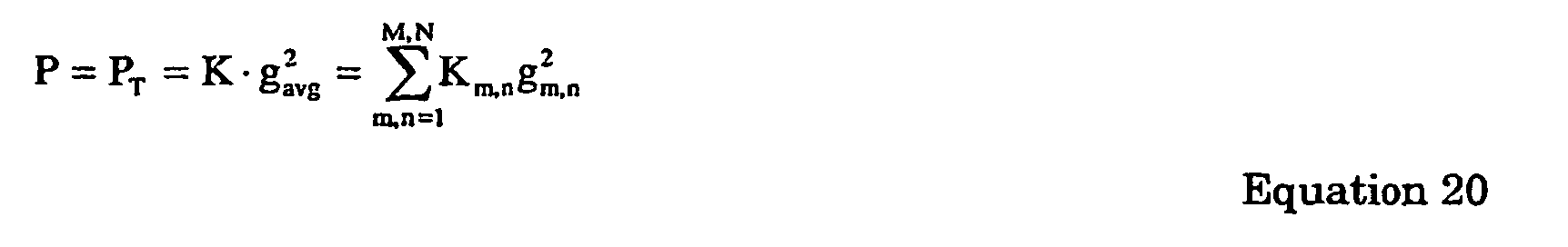
- M is the number of UEs and N is the number of CCTrCHs per UE. Km,n is the total number of codes in the nth CCTrCH of the mth UE and gm,n is the gain factor for the nth CCTrCH of the mth UE.
- Total power scaling tends to optimize performance over all connections equally and not to optimize any connection over the others. To illustrate, the code power matrix G is per Equation 21.

-


- The solution of least-square-error-power is the average power of all codes per Equation 23.

- K is the total number of codes transmitted in the time period of interest for the system and is per
Equation 24.
- The code power scale factor is determined by Equation 25.

-

Equation 26.
- As illustrated, total power scaling is optimal over all connections by minimizing the code power mismatch over all connections.
- In selective code power scaling, P is determined to optimize a particular UE connection. To optimize ajth UE's connection, Equation 27 is used.

αj is a factor for the jth UE that is based on the interference and noise level. αj should be adaptively adjusted based on the interference and noise level for optimum performance of the data detection. Two preferred equations for deriving αj are perEquations 28 and 29.

Kj is the total number of codes carried by that jth UE. Ki,j is the number of codes for the ith CCTrCH of the jth UE. gi,j is the gain factor for the ith CCTrCH for the jth UE. I is the number of CCTrCHs of the UE. - Selective code power scaling may also be used to optimize a particular CCTrCH of a UE. To optimize the ith CCTrCH of the jth UE,
Equation 30 is used.
αi,j is a factor for the ith CCTrCH of the jth UE. - Selective code power scaling may also be used to optimize a particular code of a particular CCTrCH of a UE. To optimize the nth code of the ith CCTrCH of the jth UE, Equation 31 is used.

- αn,i,j is a factor for the nth code of the ith CCTrCH of the jth UE. Two preferred equations for determining αn,i,j are
Equations 32 and 33.

- Two special cases of selective code power scaling are maximum code power and minimum code power scaling. In maximum code power scaling, the maximum code power is used for the scaling. Maximum code power scaling is most applicable when the over-scaling of code power degrades less than the under-scaling of code power. In minimum code power scaling, the minimum code power is used for scaling. Minimum code power scaling is most applicable when the under-scaling of code power degrades less than the over-scaling of code power.
-
Figure 2 is one flow chart for applying code power scaling. One UE or UE's CCTrCH is selected for optimum performance,Step 70. If SUD is being performed at the UE the selected CCTrCH is typically with the highest required QOS. If SUD is being performed at the base station, the UE of interest may be the farthest UE, to reduce that UE's transmission power level. Alternatively, the UE or UE CCTrCH of interest may be the UE or UE CCTrCH requiring the highest quality of service. For the UE/UE CCTrCH of interest, the gain factor(s) for that UE/CCTrCH is determined,Step 72. The code scaling factor P is determined from the gain factor(s). SUD is performed using the determined P,Step 74. The code scaling factor P is used in the data detection, such as by scalingdevices Step 76. As a result, that UE's/LTE CCTrCH's performance is optimized. -
Figure 3 is a flow chart for total power scaling. Total power scaling is preferably performed if all the CCTrCHs at a UE or base station require the same QOS. Additionally, total power scaling may be applied to reduce the complexity by eliminating the need to optimize the SUD for a particular UE. The gain factors of all UE codes are determined,Step 78, and the resulting code scaling factor P is determined,Step 80. The SUD is performed using the determined P,Step 82. This approach equally optimizes all codes. - In some cases P is not necessarily determined from the gain factors. For instance, when a common midamble is used in a downlink allocation, the estimated channel response, H', has the total power information. Accordingly, the total power is embedded in the estimated channel response at the output of the channel estimator, i.e.

Figure 3 in this situation can be avoided. -
Figure 4 is a flow chart of iterative selective code power scaling. To optimize the performances, each UE or UE CCTrCH can be optimized. Sequentially for each UE/UE CCTrCH, the gain factor(s) are determined and the resulting code scaling factor P is determined,Step 86. Using P, SUD is performed and the data for that UE/UE CCTrCH is estimated,Step 88. The process is repeated until each of the UEs/LTE CCTrCHs have been processed or all the UEs/UE CCTrCHs of interest have been processed,Step 90. This approach optimizes overall performance for each UE/LTE CCTrCH at the expense of added complexity and delay. -
Figures 5A and 5B are simplified block diagrams of gain factor scaling used in a multiuser detection receiver. In multiuser detection, data from all codes is detected simultaneously. These approaches to data detection can also experience improved performance by using gain factor scaling. - In
Figure 5A , the received communications are received by anantenna 100 or antenna array. The received communications are demodulated to baseband by ademodulator 102. The baseband signal is sampled by asampling device 104 to produce a received vector, r. Achannel estimation device 106 estimates the channel response as a channel response matrix, H. The noise variance σ 2 is also determined, such as by thechannel estimation device 106 or by another device. The noise variance σ2 is scaled by ascaling device 110, such as by a value 1/P. The channel response matrix H and the noise variance σ2 as well as the received vector and spreading codes C are input into amultiuser detection device 108. Themultiuser detection device 108 produces a data vector d. - In an alternate approach as shown in
Figure 5B , the channel response matrix H is scaled. The received communications are received by anantenna 112 or antenna array. The received communications are demodulated to baseband by ademodulator 114. The baseband signal is sampled by asampling device 116 to produce a received vector, r. Achannel estimation device 118 estimates the channel response as a channel response matrix, H. The noise variance σ2 is also determined, such as by thechannel estimation device 118 or by another device. The channel response matrix H is scaled by ascaling device 122, such as by a value
multiuser detection device 120. Themultiuser detection device 120 produces a data vector d. Preferably, for use with multiuser detectors, P is derived using total power scaling. - Alternately, the gain factor scaling can be performed in conjunction with the multiuser detection. For such gain scaling, the
multiuser detection device
Claims (18)
- A method of recovering data from a plurality of communications transmitted in a code division multiple access communication system, the method comprising:receiving the communications;determining (72, 78, 84) gain factors for at least one of the received communications; anddetecting data of the received communications using a scaling factor derived from the determined gain values, wherein the detecting comprisesestimating a channel response and a noise variance of the communications; the method characterized by the detecting further comprising:scaling the noise variance using a scaling factor, the scaling factor derived (74, 80, 86) from at least one gain factor of the received communications;channel equalizing the received communications using the estimated channel response and the scaled noise variance; anddespreading the channel equalized received communications to recover data of the received communications.
- The method of claim 1, wherein the detecting data using a scaling factor further comprises scaling the channel equalized received communications using the scaling factor.
- The method of claim 1, wherein the at least one gain factor is a gain factor of a communication of interest.
- The method of claim 1, wherein the scaling factor is derived from gain factors from all of the received communications.
- The method of claim 1, wherein the scaling factor is derived from gain factors from a coded composite transport channel of interest.
- The method of claim 1, wherein the detecting data using a scaling factor utilizes a multiuser detection device.
- A wireless spread spectrum user equipment (20) comprising:an antenna (28) for receiving a plurality of communications, the communications transmitted in a shared spectrum; anda channel estimation device (58) for estimating a channel response and a noise variance of the received communications; characterized by a scaling device (60) for obtaining a scaled input as a scaled version of the noise variance, saidscaled input scaled by a factor derived from at least one gain factor of the received communications;
a data estimation device (62, 64, 66), for receiving the scaled input and adapted to use the channel response and the received communications to detect data of the received communications, the data estimation device comprising a channel equalizer (62) for equalizing the received communications and a despreader (66) to despread the equalized received communications to recover data of the received communications. - The user equipment of claim 7, wherein the data estimation device comprises a multiuser detection device.
- The user equipment of claim 7, wherein the equalized received communication are scaled by a scaling factor derived from at least one gain factor.
- The user equipment of claim 7, wherein the at least one gain factor is a gain factor of a communication of interest.
- The user equipment of claim 7, wherein the scaling factor is derived from gain factors from all of the received communications.
- The user equipment of claim 7, wherein the scaling factor is derived from gain factors from a coded composite transport channel of interest.
- A wireless spread spectrum base station (22) comprising:an antenna (32) for receiving a plurality of communications, the communications transmitted in a shared spectrum; anda channel estimation device (38) for estimating a channel response and a noise variance of the received communications; characterized bya scaling device (40) for obtaining a scaled input as a scaled version of the noise variance, said a data scaled input scaled by a factor derived from at least one gain factor of the received communication; estimation device (42, 44, 46) for receiving the scaled input, the data estimation device adapted to use the channel response and the received communications to detect data of the received communications, the data estimation device comprising a channel equalizer (42) for equalizing the received communications and a despreader (46) to despread the equalized received communications to recover data of the received communications.
- The base station of claim 13, wherein the data estimation device comprises a multiuser detection device.
- The base station of claim 13, wherein the equalized received communication are scaled by a scaling factor derived from at least one gain factor.
- The base station of claim 13, wherein the at least one gain factor is a gain factor of a communication of interest.
- The base station of claim 13, wherein the scaling factor is derived from gain factors from all of the received communications.
- The base station of claim 13 wherein, the scaling factor is derived from gain factors from a coded composite transport channel of interest.
Applications Claiming Priority (5)
| Application Number | Priority Date | Filing Date | Title |
|---|---|---|---|
| US39682302P | 2002-07-18 | 2002-07-18 | |
| US396823P | 2002-07-18 | ||
| US327299 | 2002-12-20 | ||
| US10/327,299 US6928104B2 (en) | 2002-07-18 | 2002-12-20 | Scaling using gain factors for use in data detection for wireless code division multiple access communication systems |
| PCT/US2003/021293 WO2004023696A2 (en) | 2002-07-18 | 2003-07-09 | Scaling using gain factors for use in data detection for wireless code division multiple access communication systems |
Publications (3)
| Publication Number | Publication Date |
|---|---|
| EP1523810A2 EP1523810A2 (en) | 2005-04-20 |
| EP1523810A4 EP1523810A4 (en) | 2005-11-02 |
| EP1523810B1 true EP1523810B1 (en) | 2008-05-14 |
Family
ID=30448158
Family Applications (1)
| Application Number | Title | Priority Date | Filing Date |
|---|---|---|---|
| EP03794437A Expired - Lifetime EP1523810B1 (en) | 2002-07-18 | 2003-07-09 | Scaling using gain factors for use in data detection for wireless code division multiple access communication systems |
Country Status (14)
| Country | Link |
|---|---|
| US (5) | US6928104B2 (en) |
| EP (1) | EP1523810B1 (en) |
| JP (2) | JP2005533460A (en) |
| KR (2) | KR100808895B1 (en) |
| CN (1) | CN1768485B (en) |
| AT (1) | ATE395753T1 (en) |
| AU (1) | AU2003298522A1 (en) |
| CA (1) | CA2492677A1 (en) |
| DE (1) | DE60320996D1 (en) |
| ES (1) | ES2306915T3 (en) |
| MX (1) | MXPA05000786A (en) |
| NO (1) | NO20050601L (en) |
| TW (3) | TWI237456B (en) |
| WO (1) | WO2004023696A2 (en) |
Families Citing this family (35)
| Publication number | Priority date | Publication date | Assignee | Title |
|---|---|---|---|---|
| US6928104B2 (en) * | 2002-07-18 | 2005-08-09 | Interdigital Technology Corporation | Scaling using gain factors for use in data detection for wireless code division multiple access communication systems |
| US20060013181A1 (en) * | 2002-07-31 | 2006-01-19 | Victor Stolpman | Apparatus, and associated method, for allocating communications in a multi-channel communication system |
| US7257170B2 (en) * | 2002-08-21 | 2007-08-14 | Texas Instruments Incorporated | Channel norm-based ordering and whitened decoding for MIMO communication systems |
| US7715508B2 (en) | 2005-11-15 | 2010-05-11 | Tensorcomm, Incorporated | Iterative interference cancellation using mixed feedback weights and stabilizing step sizes |
| US8005128B1 (en) * | 2003-09-23 | 2011-08-23 | Rambus Inc. | Methods for estimation and interference cancellation for signal processing |
| US7340013B2 (en) * | 2002-10-24 | 2008-03-04 | Agere Systems Inc. | Soft sample scaling in a turbo decoder |
| US7161973B2 (en) * | 2002-12-17 | 2007-01-09 | Sbc Properties, L.P. | Pilot aided adaptive minimum mean square interference cancellation and detection |
| US6937644B2 (en) * | 2003-01-10 | 2005-08-30 | Interdigital Technology Corporation | Generalized two-stage data estimation |
| US7627021B2 (en) * | 2003-01-30 | 2009-12-01 | The Mitre Corporation | Interference canceling CDMA mobile station receiver |
| US7099378B2 (en) * | 2003-01-30 | 2006-08-29 | The Mitre Corporation | Sub-symbol parallel interference cancellation |
| GB2404822B (en) * | 2003-08-07 | 2007-07-11 | Ipwireless Inc | Method and arrangement for noise variance and sir estimation |
| US7437135B2 (en) * | 2003-10-30 | 2008-10-14 | Interdigital Technology Corporation | Joint channel equalizer interference canceller advanced receiver |
| US7627059B2 (en) * | 2005-04-05 | 2009-12-01 | Samsung Electronics Co., Ltd. | Method of robust timing detection and carrier frequency offset estimation for OFDM systems |
| US7711075B2 (en) | 2005-11-15 | 2010-05-04 | Tensorcomm Incorporated | Iterative interference cancellation using mixed feedback weights and stabilizing step sizes |
| US7826516B2 (en) | 2005-11-15 | 2010-11-02 | Rambus Inc. | Iterative interference canceller for wireless multiple-access systems with multiple receive antennas |
| US7991088B2 (en) | 2005-11-15 | 2011-08-02 | Tommy Guess | Iterative interference cancellation using mixed feedback weights and stabilizing step sizes |
| US7616699B2 (en) * | 2005-04-12 | 2009-11-10 | Samsung Electronics Co., Ltd. | Method of soft bit metric calculation with direct matrix inversion MIMO detection |
| KR100724986B1 (en) | 2005-06-28 | 2007-06-04 | 삼성전자주식회사 | Method and apparatus for deciding a scaling factor for turbo decoder input data in cdma system |
| US20070076791A1 (en) * | 2005-07-26 | 2007-04-05 | Interdigital Technology Corporation | Approximate cholesky decomposition-based block linear equalizer |
| KR100651913B1 (en) * | 2005-08-26 | 2006-12-01 | 엘지전자 주식회사 | Equalizer in receiver of orthogonal frequency division multiplexed signals |
| US7702048B2 (en) * | 2005-11-15 | 2010-04-20 | Tensorcomm, Incorporated | Iterative interference cancellation using mixed feedback weights and stabilizing step sizes |
| US20070110135A1 (en) * | 2005-11-15 | 2007-05-17 | Tommy Guess | Iterative interference cancellation for MIMO-OFDM receivers |
| US7623602B2 (en) * | 2005-11-15 | 2009-11-24 | Tensorcomm, Inc. | Iterative interference canceller for wireless multiple-access systems employing closed loop transmit diversity |
| US7751506B2 (en) | 2005-12-01 | 2010-07-06 | Samsung Electronics Co., Ltd. | Method for the soft bit metric calculation with linear MIMO detection for LDPC codes |
| EP1988645A4 (en) | 2006-02-01 | 2014-01-15 | Nec Corp | Equalization device and equalization method |
| WO2007127911A2 (en) * | 2006-04-28 | 2007-11-08 | University Of Pittsburgh Of The Commonwealth System Of Higher Education | Determining the three-dimensional read accuracy of an rfid tag using a power scaling factor |
| US7664512B2 (en) * | 2006-08-10 | 2010-02-16 | L3 Communications Integrated Systems, L.P. | Datalink throughput reduction via energy detection |
| US7924948B2 (en) * | 2006-09-29 | 2011-04-12 | Mediatek Inc. | Pre-scaling of initial channel estimates in joint detection |
| US8781043B2 (en) * | 2006-11-15 | 2014-07-15 | Qualcomm Incorporated | Successive equalization and cancellation and successive mini multi-user detection for wireless communication |
| US7974334B2 (en) * | 2007-01-30 | 2011-07-05 | Texas Instruments Incorporated | Systems and methods for hybrid-MIMO equalization |
| US20080181324A1 (en) * | 2007-01-30 | 2008-07-31 | Texas Instruments Incorporated | Systems and methods for scaling to equalize noise variance |
| KR100969781B1 (en) * | 2007-01-31 | 2010-07-13 | 삼성전자주식회사 | Apparatus and method for determining scaling factor in communication system |
| CN102668611A (en) | 2009-11-27 | 2012-09-12 | 高通股份有限公司 | Interference cancellation for non-orthogonal channel sets |
| US8942331B2 (en) * | 2012-07-12 | 2015-01-27 | Qualcomm Incorporated | Apparatus and method for improving the performance of a linear equalizer with multiple receive antennas |
| EP3270554B1 (en) * | 2016-07-12 | 2019-03-20 | Mitsubishi Electric R&D Centre Europe B.V. | Channel estimation with coloured noise |
Family Cites Families (22)
| Publication number | Priority date | Publication date | Assignee | Title |
|---|---|---|---|---|
| US5583886A (en) * | 1992-12-03 | 1996-12-10 | Motorola, Inc. | Method for determining a plurality of channel responses and modifying a received signal therewith |
| US5619525A (en) | 1995-06-06 | 1997-04-08 | Globalstar L.P. | Closed loop power control for low earth orbit satellite communications system |
| US5737327A (en) * | 1996-03-29 | 1998-04-07 | Motorola, Inc. | Method and apparatus for demodulation and power control bit detection in a spread spectrum communication system |
| KR100194956B1 (en) | 1996-08-21 | 1999-06-15 | 정선종 | Adaptive Power Control Method for Code Division Multiple Access Mobile Radiotelephone System |
| US6356639B1 (en) | 1997-04-11 | 2002-03-12 | Matsushita Electric Industrial Co., Ltd. | Audio decoding apparatus, signal processing device, sound image localization device, sound image control method, audio signal processing device, and audio signal high-rate reproduction method used for audio visual equipment |
| US6175588B1 (en) | 1997-12-30 | 2001-01-16 | Motorola, Inc. | Communication device and method for interference suppression using adaptive equalization in a spread spectrum communication system |
| US6085104A (en) * | 1998-03-25 | 2000-07-04 | Sharp Laboratories Of America, Inc. | Pilot aided, time-varying finite impulse response, adaptive channel matching receiving system and method |
| KR100301284B1 (en) | 1998-04-10 | 2001-10-27 | 곽경섭 | Multi-user signal receiving method and receiver of cdma system |
| TW428371B (en) | 1999-05-28 | 2001-04-01 | Acer Peripherals Inc | Radio transceiver system capable of dynamically adjusting the operating bias point of a low noise amplifier |
| US6801565B1 (en) * | 1999-06-25 | 2004-10-05 | Ericsson Inc. | Multi-stage rake combining methods and apparatus |
| US6151358A (en) * | 1999-08-11 | 2000-11-21 | Motorola, Inc. | Method and apparatus, and computer program for producing filter coefficients for equalizers |
| US6590932B1 (en) * | 1999-11-24 | 2003-07-08 | Ericsson Inc. | Methods, receiver devices and systems for whitening a signal disturbance in a communication signal |
| FI20000820A (en) * | 2000-04-06 | 2001-10-07 | Nokia Networks Oy | Channel qualifier optimization |
| US6633766B1 (en) | 2000-04-24 | 2003-10-14 | Telefonaktiebolaget Lm Ericsson (Publ) | Frequency selective RF output power calibration using digital and analog power measurements for use in a cellular telecommunications system |
| JP4165629B2 (en) | 2000-04-26 | 2008-10-15 | モトローラ・インコーポレイテッド | Power measurement device for measuring received signal power and received interference power |
| US6952561B1 (en) * | 2000-08-31 | 2005-10-04 | Lucent Technologies Inc. | Enhanced metric for bit detection on fading channels with unknown statistics |
| JP3853790B2 (en) * | 2001-09-18 | 2006-12-06 | インターディジタル テクノロジー コーポレイション | Method and apparatus for estimating interference signal code power and noise variance |
| US7035353B2 (en) * | 2001-10-24 | 2006-04-25 | Zenith Electronics Corporation | Channel estimation method blending correlation and least-squares based approaches |
| US20030125040A1 (en) * | 2001-11-06 | 2003-07-03 | Walton Jay R. | Multiple-access multiple-input multiple-output (MIMO) communication system |
| US7346126B2 (en) * | 2001-11-28 | 2008-03-18 | Telefonaktiebolaget L M Ericsson (Publ) | Method and apparatus for channel estimation using plural channels |
| US6862271B2 (en) * | 2002-02-26 | 2005-03-01 | Qualcomm Incorporated | Multiple-input, multiple-output (MIMO) systems with multiple transmission modes |
| US6928104B2 (en) * | 2002-07-18 | 2005-08-09 | Interdigital Technology Corporation | Scaling using gain factors for use in data detection for wireless code division multiple access communication systems |
-
2002
- 2002-12-20 US US10/327,299 patent/US6928104B2/en not_active Expired - Fee Related
-
2003
- 2003-07-09 DE DE60320996T patent/DE60320996D1/en not_active Expired - Lifetime
- 2003-07-09 AU AU2003298522A patent/AU2003298522A1/en not_active Abandoned
- 2003-07-09 CA CA002492677A patent/CA2492677A1/en not_active Abandoned
- 2003-07-09 KR KR1020057000936A patent/KR100808895B1/en not_active IP Right Cessation
- 2003-07-09 KR KR1020057017512A patent/KR20050098026A/en active IP Right Grant
- 2003-07-09 EP EP03794437A patent/EP1523810B1/en not_active Expired - Lifetime
- 2003-07-09 JP JP2004534242A patent/JP2005533460A/en not_active Ceased
- 2003-07-09 WO PCT/US2003/021293 patent/WO2004023696A2/en active Application Filing
- 2003-07-09 MX MXPA05000786A patent/MXPA05000786A/en active IP Right Grant
- 2003-07-09 ES ES03794437T patent/ES2306915T3/en not_active Expired - Lifetime
- 2003-07-09 AT AT03794437T patent/ATE395753T1/en not_active IP Right Cessation
- 2003-07-09 CN CN038170698A patent/CN1768485B/en not_active Expired - Fee Related
- 2003-07-14 TW TW092119189A patent/TWI237456B/en not_active IP Right Cessation
- 2003-07-14 TW TW093105622A patent/TW200501622A/en unknown
- 2003-07-14 TW TW095126608A patent/TWI320640B/en not_active IP Right Cessation
-
2005
- 2005-02-03 NO NO20050601A patent/NO20050601L/en not_active Application Discontinuation
- 2005-07-06 US US11/175,662 patent/US7042929B2/en not_active Expired - Fee Related
- 2005-08-22 JP JP2005240061A patent/JP4385015B2/en not_active Expired - Fee Related
-
2006
- 2006-04-21 US US11/408,411 patent/US7313172B2/en not_active Expired - Fee Related
-
2007
- 2007-12-21 US US11/962,371 patent/US7583722B2/en not_active Expired - Fee Related
-
2009
- 2009-08-28 US US12/549,912 patent/US8189648B2/en not_active Expired - Fee Related
Also Published As
Similar Documents
| Publication | Publication Date | Title |
|---|---|---|
| EP1523810B1 (en) | Scaling using gain factors for use in data detection for wireless code division multiple access communication systems | |
| EP1391048B9 (en) | Fast joint detection | |
| EP1686696B1 (en) | Single user detection | |
| EP1274179A1 (en) | Method for signal processing used in terminal device of code division multiple access mobile communication system | |
| US7161972B2 (en) | Method and apparatus for downlink joint detection in a communication system | |
| US8259854B2 (en) | Channel estimation using common and dedicated pilots | |
| US6757321B2 (en) | Segment-wise channel equalization based data estimation | |
| US20030185192A1 (en) | Transmit processing using receiver functions |
Legal Events
| Date | Code | Title | Description |
|---|---|---|---|
| PUAI | Public reference made under article 153(3) epc to a published international application that has entered the european phase |
Free format text: ORIGINAL CODE: 0009012 |
|
| 17P | Request for examination filed |
Effective date: 20050119 |
|
| AK | Designated contracting states |
Kind code of ref document: A2 Designated state(s): AT BE BG CH CY CZ DE DK EE ES FI FR GB GR HU IE IT LI LU MC NL PT RO SE SI SK TR |
|
| AX | Request for extension of the european patent |
Extension state: AL LT LV MK |
|
| A4 | Supplementary search report drawn up and despatched |
Effective date: 20050916 |
|
| DAX | Request for extension of the european patent (deleted) | ||
| 17Q | First examination report despatched |
Effective date: 20051227 |
|
| GRAP | Despatch of communication of intention to grant a patent |
Free format text: ORIGINAL CODE: EPIDOSNIGR1 |
|
| GRAS | Grant fee paid |
Free format text: ORIGINAL CODE: EPIDOSNIGR3 |
|
| RAP1 | Party data changed (applicant data changed or rights of an application transferred) |
Owner name: INTERDIGITAL TECHNOLOGY CORPORATION |
|
| GRAA | (expected) grant |
Free format text: ORIGINAL CODE: 0009210 |
|
| AK | Designated contracting states |
Kind code of ref document: B1 Designated state(s): AT BE BG CH CY CZ DE DK EE ES FI FR GB GR HU IE IT LI LU MC NL PT RO SE SI SK TR |
|
| REG | Reference to a national code |
Ref country code: GB Ref legal event code: FG4D |
|
| REG | Reference to a national code |
Ref country code: CH Ref legal event code: EP |
|
| REG | Reference to a national code |
Ref country code: IE Ref legal event code: FG4D Free format text: LANGUAGE OF EP DOCUMENT: FRENCH |
|
| REF | Corresponds to: |
Ref document number: 60320996 Country of ref document: DE Date of ref document: 20080626 Kind code of ref document: P |
|
| REG | Reference to a national code |
Ref country code: SE Ref legal event code: TRGR |
|
| PG25 | Lapsed in a contracting state [announced via postgrant information from national office to epo] |
Ref country code: SI Free format text: LAPSE BECAUSE OF FAILURE TO SUBMIT A TRANSLATION OF THE DESCRIPTION OR TO PAY THE FEE WITHIN THE PRESCRIBED TIME-LIMIT Effective date: 20080514 |
|
| NLV1 | Nl: lapsed or annulled due to failure to fulfill the requirements of art. 29p and 29m of the patents act | ||
| REG | Reference to a national code |
Ref country code: ES Ref legal event code: FG2A Ref document number: 2306915 Country of ref document: ES Kind code of ref document: T3 |
|
| PG25 | Lapsed in a contracting state [announced via postgrant information from national office to epo] |
Ref country code: AT Free format text: LAPSE BECAUSE OF FAILURE TO SUBMIT A TRANSLATION OF THE DESCRIPTION OR TO PAY THE FEE WITHIN THE PRESCRIBED TIME-LIMIT Effective date: 20080514 Ref country code: NL Free format text: LAPSE BECAUSE OF FAILURE TO SUBMIT A TRANSLATION OF THE DESCRIPTION OR TO PAY THE FEE WITHIN THE PRESCRIBED TIME-LIMIT Effective date: 20080514 |
|
| PG25 | Lapsed in a contracting state [announced via postgrant information from national office to epo] |
Ref country code: DK Free format text: LAPSE BECAUSE OF FAILURE TO SUBMIT A TRANSLATION OF THE DESCRIPTION OR TO PAY THE FEE WITHIN THE PRESCRIBED TIME-LIMIT Effective date: 20080514 Ref country code: CZ Free format text: LAPSE BECAUSE OF FAILURE TO SUBMIT A TRANSLATION OF THE DESCRIPTION OR TO PAY THE FEE WITHIN THE PRESCRIBED TIME-LIMIT Effective date: 20080514 Ref country code: PT Free format text: LAPSE BECAUSE OF FAILURE TO SUBMIT A TRANSLATION OF THE DESCRIPTION OR TO PAY THE FEE WITHIN THE PRESCRIBED TIME-LIMIT Effective date: 20081014 |
|
| PG25 | Lapsed in a contracting state [announced via postgrant information from national office to epo] |
Ref country code: RO Free format text: LAPSE BECAUSE OF FAILURE TO SUBMIT A TRANSLATION OF THE DESCRIPTION OR TO PAY THE FEE WITHIN THE PRESCRIBED TIME-LIMIT Effective date: 20080514 Ref country code: BE Free format text: LAPSE BECAUSE OF FAILURE TO SUBMIT A TRANSLATION OF THE DESCRIPTION OR TO PAY THE FEE WITHIN THE PRESCRIBED TIME-LIMIT Effective date: 20080514 Ref country code: SK Free format text: LAPSE BECAUSE OF FAILURE TO SUBMIT A TRANSLATION OF THE DESCRIPTION OR TO PAY THE FEE WITHIN THE PRESCRIBED TIME-LIMIT Effective date: 20080514 |
|
| REG | Reference to a national code |
Ref country code: CH Ref legal event code: PL |
|
| PLBE | No opposition filed within time limit |
Free format text: ORIGINAL CODE: 0009261 |
|
| STAA | Information on the status of an ep patent application or granted ep patent |
Free format text: STATUS: NO OPPOSITION FILED WITHIN TIME LIMIT |
|
| PG25 | Lapsed in a contracting state [announced via postgrant information from national office to epo] |
Ref country code: MC Free format text: LAPSE BECAUSE OF NON-PAYMENT OF DUE FEES Effective date: 20080731 |
|
| 26N | No opposition filed |
Effective date: 20090217 |
|
| PG25 | Lapsed in a contracting state [announced via postgrant information from national office to epo] |
Ref country code: BG Free format text: LAPSE BECAUSE OF FAILURE TO SUBMIT A TRANSLATION OF THE DESCRIPTION OR TO PAY THE FEE WITHIN THE PRESCRIBED TIME-LIMIT Effective date: 20080814 Ref country code: EE Free format text: LAPSE BECAUSE OF FAILURE TO SUBMIT A TRANSLATION OF THE DESCRIPTION OR TO PAY THE FEE WITHIN THE PRESCRIBED TIME-LIMIT Effective date: 20080514 |
|
| PG25 | Lapsed in a contracting state [announced via postgrant information from national office to epo] |
Ref country code: CH Free format text: LAPSE BECAUSE OF NON-PAYMENT OF DUE FEES Effective date: 20080731 Ref country code: LI Free format text: LAPSE BECAUSE OF NON-PAYMENT OF DUE FEES Effective date: 20080731 |
|
| PG25 | Lapsed in a contracting state [announced via postgrant information from national office to epo] |
Ref country code: IE Free format text: LAPSE BECAUSE OF NON-PAYMENT OF DUE FEES Effective date: 20080709 |
|
| PG25 | Lapsed in a contracting state [announced via postgrant information from national office to epo] |
Ref country code: CY Free format text: LAPSE BECAUSE OF FAILURE TO SUBMIT A TRANSLATION OF THE DESCRIPTION OR TO PAY THE FEE WITHIN THE PRESCRIBED TIME-LIMIT Effective date: 20080514 Ref country code: HU Free format text: LAPSE BECAUSE OF FAILURE TO SUBMIT A TRANSLATION OF THE DESCRIPTION OR TO PAY THE FEE WITHIN THE PRESCRIBED TIME-LIMIT Effective date: 20081115 Ref country code: LU Free format text: LAPSE BECAUSE OF NON-PAYMENT OF DUE FEES Effective date: 20080709 |
|
| PG25 | Lapsed in a contracting state [announced via postgrant information from national office to epo] |
Ref country code: TR Free format text: LAPSE BECAUSE OF FAILURE TO SUBMIT A TRANSLATION OF THE DESCRIPTION OR TO PAY THE FEE WITHIN THE PRESCRIBED TIME-LIMIT Effective date: 20080514 |
|
| PG25 | Lapsed in a contracting state [announced via postgrant information from national office to epo] |
Ref country code: GR Free format text: LAPSE BECAUSE OF FAILURE TO SUBMIT A TRANSLATION OF THE DESCRIPTION OR TO PAY THE FEE WITHIN THE PRESCRIBED TIME-LIMIT Effective date: 20080815 |
|
| PGFP | Annual fee paid to national office [announced via postgrant information from national office to epo] |
Ref country code: ES Payment date: 20140611 Year of fee payment: 12 |
|
| PGFP | Annual fee paid to national office [announced via postgrant information from national office to epo] |
Ref country code: DE Payment date: 20140702 Year of fee payment: 12 Ref country code: FI Payment date: 20140710 Year of fee payment: 12 |
|
| PGFP | Annual fee paid to national office [announced via postgrant information from national office to epo] |
Ref country code: FR Payment date: 20140708 Year of fee payment: 12 Ref country code: GB Payment date: 20140709 Year of fee payment: 12 Ref country code: SE Payment date: 20140711 Year of fee payment: 12 |
|
| PGFP | Annual fee paid to national office [announced via postgrant information from national office to epo] |
Ref country code: IT Payment date: 20140714 Year of fee payment: 12 |
|
| REG | Reference to a national code |
Ref country code: DE Ref legal event code: R119 Ref document number: 60320996 Country of ref document: DE |
|
| REG | Reference to a national code |
Ref country code: SE Ref legal event code: EUG |
|
| GBPC | Gb: european patent ceased through non-payment of renewal fee |
Effective date: 20150709 |
|
| PG25 | Lapsed in a contracting state [announced via postgrant information from national office to epo] |
Ref country code: IT Free format text: LAPSE BECAUSE OF NON-PAYMENT OF DUE FEES Effective date: 20150709 Ref country code: GB Free format text: LAPSE BECAUSE OF NON-PAYMENT OF DUE FEES Effective date: 20150709 Ref country code: DE Free format text: LAPSE BECAUSE OF NON-PAYMENT OF DUE FEES Effective date: 20160202 |
|
| REG | Reference to a national code |
Ref country code: FR Ref legal event code: ST Effective date: 20160331 |
|
| PG25 | Lapsed in a contracting state [announced via postgrant information from national office to epo] |
Ref country code: FR Free format text: LAPSE BECAUSE OF NON-PAYMENT OF DUE FEES Effective date: 20150731 Ref country code: SE Free format text: LAPSE BECAUSE OF NON-PAYMENT OF DUE FEES Effective date: 20150710 Ref country code: FI Free format text: LAPSE BECAUSE OF NON-PAYMENT OF DUE FEES Effective date: 20150709 |
|
| PG25 | Lapsed in a contracting state [announced via postgrant information from national office to epo] |
Ref country code: ES Free format text: LAPSE BECAUSE OF NON-PAYMENT OF DUE FEES Effective date: 20150710 |