EP1523946A1 - Clip operation device - Google Patents
Clip operation device Download PDFInfo
- Publication number
- EP1523946A1 EP1523946A1 EP03741426A EP03741426A EP1523946A1 EP 1523946 A1 EP1523946 A1 EP 1523946A1 EP 03741426 A EP03741426 A EP 03741426A EP 03741426 A EP03741426 A EP 03741426A EP 1523946 A1 EP1523946 A1 EP 1523946A1
- Authority
- EP
- European Patent Office
- Prior art keywords
- clip
- wire
- manipulating
- distal end
- insertion tube
- Prior art date
- Legal status (The legal status is an assumption and is not a legal conclusion. Google has not performed a legal analysis and makes no representation as to the accuracy of the status listed.)
- Granted
Links
- 238000003780 insertion Methods 0.000 claims description 75
- 230000037431 insertion Effects 0.000 claims description 75
- 230000008878 coupling Effects 0.000 claims description 41
- 238000010168 coupling process Methods 0.000 claims description 41
- 238000005859 coupling reaction Methods 0.000 claims description 41
- 230000000694 effects Effects 0.000 claims description 13
- 230000009471 action Effects 0.000 claims description 3
- 206010013975 Dyspnoeas Diseases 0.000 claims 1
- 238000000034 method Methods 0.000 description 9
- 239000000463 material Substances 0.000 description 5
- 230000008569 process Effects 0.000 description 5
- 230000007480 spreading Effects 0.000 description 4
- 238000004873 anchoring Methods 0.000 description 3
- 238000005452 bending Methods 0.000 description 2
- 238000010276 construction Methods 0.000 description 2
- 239000011347 resin Substances 0.000 description 2
- 229920005989 resin Polymers 0.000 description 2
- 229910001220 stainless steel Inorganic materials 0.000 description 2
- 239000010935 stainless steel Substances 0.000 description 2
- 239000000853 adhesive Substances 0.000 description 1
- 230000001070 adhesive effect Effects 0.000 description 1
- 230000005540 biological transmission Effects 0.000 description 1
- 230000000740 bleeding effect Effects 0.000 description 1
- 239000000945 filler Substances 0.000 description 1
- 239000002184 metal Substances 0.000 description 1
- 230000004048 modification Effects 0.000 description 1
- 238000012986 modification Methods 0.000 description 1
- 230000002093 peripheral effect Effects 0.000 description 1
- 229920001296 polysiloxane Polymers 0.000 description 1
Images


Classifications
-
- A—HUMAN NECESSITIES
- A61—MEDICAL OR VETERINARY SCIENCE; HYGIENE
- A61B—DIAGNOSIS; SURGERY; IDENTIFICATION
- A61B17/00—Surgical instruments, devices or methods, e.g. tourniquets
- A61B17/12—Surgical instruments, devices or methods, e.g. tourniquets for ligaturing or otherwise compressing tubular parts of the body, e.g. blood vessels, umbilical cord
- A61B17/128—Surgical instruments, devices or methods, e.g. tourniquets for ligaturing or otherwise compressing tubular parts of the body, e.g. blood vessels, umbilical cord for applying or removing clamps or clips
- A61B17/1285—Surgical instruments, devices or methods, e.g. tourniquets for ligaturing or otherwise compressing tubular parts of the body, e.g. blood vessels, umbilical cord for applying or removing clamps or clips for minimally invasive surgery
-
- A—HUMAN NECESSITIES
- A61—MEDICAL OR VETERINARY SCIENCE; HYGIENE
- A61B—DIAGNOSIS; SURGERY; IDENTIFICATION
- A61B17/00—Surgical instruments, devices or methods, e.g. tourniquets
- A61B17/12—Surgical instruments, devices or methods, e.g. tourniquets for ligaturing or otherwise compressing tubular parts of the body, e.g. blood vessels, umbilical cord
- A61B17/122—Clamps or clips, e.g. for the umbilical cord
- A61B17/1227—Spring clips
-
- A—HUMAN NECESSITIES
- A61—MEDICAL OR VETERINARY SCIENCE; HYGIENE
- A61B—DIAGNOSIS; SURGERY; IDENTIFICATION
- A61B17/00—Surgical instruments, devices or methods, e.g. tourniquets
- A61B17/00234—Surgical instruments, devices or methods, e.g. tourniquets for minimally invasive surgery
- A61B2017/00292—Surgical instruments, devices or methods, e.g. tourniquets for minimally invasive surgery mounted on or guided by flexible, e.g. catheter-like, means
- A61B2017/003—Steerable
-
- A—HUMAN NECESSITIES
- A61—MEDICAL OR VETERINARY SCIENCE; HYGIENE
- A61B—DIAGNOSIS; SURGERY; IDENTIFICATION
- A61B90/00—Instruments, implements or accessories specially adapted for surgery or diagnosis and not covered by any of the groups A61B1/00 - A61B50/00, e.g. for luxation treatment or for protecting wound edges
- A61B90/03—Automatic limiting or abutting means, e.g. for safety
- A61B2090/037—Automatic limiting or abutting means, e.g. for safety with a frangible part, e.g. by reduced diameter
Definitions
- the present invention relates to a clip manipulating device or a clip device for an organic tissue in a cavity of a living body or the like as an object of treatment.
- Clip devices that are used in combination with an endoscope to arrest bleeding from a region in the body cavity are described in Jpn. UM Appln. KOKOKU Publication No. 4-26091 and Jpn. Pat. Appln. KOKOKU Publication No. 63-6016.
- a clip 53 is hitched by means of a coupling plate 54 to a hook 52, which is attached to the distal end of a manipulating wire 51 that is passed through a sheath 50, as shown in FIG. 23.
- a hook that is attached to the distal end of a manipulating wire is hitched directly to a clip.
- a rigid coupling member such as a hook or a coupling plate, is connected to the distal end of the manipulating wire.
- the clip that is located at the distal end of the sheath is detachably attached to the rigid coupling member and set in place. The clip can be opened and closed or disengaged by advancing or retreating the manipulating wire.
- the clip device of this type is guided into the body cavity through a channel of an endoscope when it is worked. Usually, it is used in combination with a straight-viewing endoscope. Depending on the region to be treated in the body cavity, however, it sometimes is very hard to carry out treatment operation through the straight-viewing endoscope. In this case, the device is used in combination with a side-viewing endoscope, as shown in FIG. 23.
- a side-viewing endoscope 56 is furnished with a forceps raising device 57 in the distal end opening of its channel.
- the forceps raising device 57 is used to raise a clip device 58 and guide the clip device 58 into the region to be treated in the body cavity.
- the clip device 58 is bent and raised by means of the forceps raising device 57, so that the distal end portion of the clip device 58 is bent particularly deep.
- the clip is attached to the distal end of an insertion tube when it is introduced into the body cavity. Thereafter, the clip is manipulated by means of the manipulating wire, whereby the clip is disengaged from the coupling member of the manipulating wire.
- the rigid coupling member e.g., the hook or the coupling plate, on the distal end of the manipulating wire moves together with the manipulating wire in the sheath, and finally moves into the rear part of the sheath.
- the distal end portion, in particular, of the sheath of the clip device is bent deep and suddenly. Therefore, the hook or the coupling plate, the rigid coupling member, is easily caught by the bent part of the sheath. It is hard for the hook or the coupling plate, the rigid coupling member, moreover, to pass smoothly through the bent part of the sheath. In some cases, therefore, a series of operations from grasping operation to disengaging operation of the clip cannot be carried out securely and smoothly.
- This problem may arise when the device is used in combination with a straight- or oblique-viewing endoscope as well as when it is used in combination with the side-viewing endoscope.
- Some straight- or oblique-viewing endoscopes may be furnished with a forceps raising device. Even in an endoscope that is furnished with no forceps raising device, the sheath may possibly suffer from a bent part when an insertion section itself is curved, for example.
- the rigid coupling member In a clip device that uses a thin sheath, in particular, the hook or the coupling plate, the rigid coupling member, is easily caught by a slightly bent part of the sheath, without regard to the type of the endoscope that is used in combination with the device. The rigid coupling member easily fails to pass smoothly through the bent part.
- the object of the present invention is to provide a clip manipulating device or a clip device, in which a clip (including a clip unit) located near the distal end of an insertion tube can be manipulated securely and quickly by means of manipulating means that is coupled to the clip or the clip unit.
- the present invention is a clip manipulating device, in which the distal end portion of a flexible wire, having pliability and movably passed through a flexible insertion tube capable of being inserted into a cavity of a living body, forms a junction which is detachably coupled with a clip located at the distal end portion of the insertion tube.
- the junction is pliable enough to follow up deformation of the insertion tube.
- the present invention is a clip manipulating device, in which elongate means is passed for advance and retreat through flexible insertion means capable of being inserted into a cavity of a living body.
- the elongate is detachably coupled to a clip, which is located at the distal end portion of the insertion means, and is not less pliable than enough to follow up deformation of the insertion means.
- the present invention is a clip manipulating device, comprising a manipulating member, which is passed for advance and retreat through a flexible insertion tube capable of being inserted into a cavity of a living body and effects grasping operation and disengaging operation of a clip located at the distal end portion of the insertion tube, and a flexible connecting member, which has one end coupled to the distal end of the manipulating member and the other end detachably coupled to the clip and is pliable enough to follow up deformation of the insertion tube.
- the present invention is a clip manipulating device, in which a coupling member is provided on the distal end of a manipulating member, which is passed for movement through a flexible insertion tube capable of being inserted into a cavity of a living body, and a wire, extending from the clip and pliable enough to follow up deformation of the insertion tube, is coupled to the coupling member.
- a clip manipulating device 1 comprises an insertion section 2 and a control section 3.
- the insertion section 2 is formed of a flexible tube sheath 4 of, e.g., resin and a coil sheath 5 as a flexible insertion tube that is passed through the tube sheath 4.
- the tube sheath 4 and the coil sheath 5 are slidable relatively to each other in the longitudinal direction.
- the proximal end of the coil sheath 5 is connected to a body 3a of the control section 3.
- a cylindrical stopper 4b that can abut against the distal end of the body 3a is fixedly fitted on the proximal end portion of the tube sheath 4.
- a clip unit 6 is attached to the distal end of the coil sheath 5.
- the clip unit 6 is composed of a clip 7 and a retainer pipe 8.
- the clip 7 is formed of a thin stainless-steel strip material that is bent in the middle. This bent part serves as a proximal end portion 7a, and those parts which are continuous with the proximal end portion 7a individually form a pair of retractable portions 7b that are spaced wider than the inside diameter of the retainer pipe 8. Strip material portions that further extend from the retractable portions 7b are crossed, and the respective one-side parts of two strip material portions that extend from the intersection for a pair of arm portions 7c, individually.
- the respective distal end portions of the arm portions 7c are bent toward each other so that the two bent parts serve as nipping portions 7d, individually.
- the pair of arm portions 7c are given aptitude for spreading such that the opposed nipping portions 7d are kept wide apart, as shown in FIG. 2.
- a hooked anchor portion 7e which is bent substantially in the shape of a J, is formed protruding backward from the proximal end portion of the clip 7.
- the anchor portion 7e constitutes a junction that is detachably coupled to the distal end of a manipulating wire 9 that is passed through the coil sheath 5.
- the anchor portion 7e is coupled to the distal end of the manipulating wire 9 for use as manipulating means, which will be mentioned later.
- the manipulating wire 9 is formed by doubling one flexible wire member, and two wire portions that are returned toward the handling side constitute manipulating means.
- a looped distal end portion that is formed by bending the one flexible wire member serves as a junction (coupling means).
- the looped distal end portion of the manipulating wire 9 is used as the junction (coupling means) that is anchored to the anchor portion 7e of the clip 7.
- the looped distal end portion of the manipulating wire 9 at which the flexible wire member is turned back is directly used to form the junction that is pliable.
- the wire member in the looped distal side part of the manipulating wire 9 forms a pliable coupling member.
- This junction has pliability such that the coil sheath 5 for use as the insertion tube can normally follow up possible deformation, such as flexure or bending.
- the clip 7 is located near the distal end of the coil sheath 5.
- the proximal end portion of the clip 7 is fitted into the retainer pipe 8 that abuts against a coil sheath end 5a, and the retainer pipe 8 is loaded with a filler, such as silicone. By doing this, the clip 7 can be tacked to the coil sheath end 5a.
- the proximal end side part of the manipulating wire 9 passes through the coil sheath 5 of the insertion section 2 to reach a longitudinally movable slider 3b on the control section 3, and is connected to the slider 3b.
- the clip unit 6 is located at the distal end of the coil sheath 5. By advancing the tube sheath 4 on the coil sheath 5, the clip unit 6 is encased in the distal end portion of the tube sheath 4. If the tube sheath 4 is retreated from this set state so that the stopper 4b abuts against the body 3a of the control section 3, as shown in FIG. 2, the respective distal end portions of the coil sheath 5 and the clip unit 6 project from the distal end of the tube sheath 4 and are exposed to the outside. When the stopper 4b runs against the body 3a of the control section 3 in this manner, the distal end portion of the coil sheath 5 forms an exposed portion 5b that projects from the distal end of the tube sheath 4.
- the insertion section 2 of the clip manipulating device 1 is guided into a patient's body through a channel 10a of a side-viewing endoscope 10 shown in FIG. 3.
- the distal end portion of the insertion section 2 of the clip manipulating device 1 is projected from the endoscope 10, the tube sheath 4 for use as a manipulating member is retreated, and the stopper 4b is caused to abut against the distal end of the body 3a of the control section 3. Thereupon, both the clip unit 6 and the exposed portion 5b of the coil sheath 5 project from the distal end of the tube sheath 4.
- a forceps raising device 10b of the endoscope 10 is raised, as shown in FIG. 3.
- the exposed portion 5b of the coil sheath 5 is intensively bent and raised by means of the forceps raising device 10b, and the clip unit 6 gets into the field of the endoscope 10.
- the exposed portion 5b of the coil sheath 5 is long enough to be curved by means of the forceps raising device 10b.
- the exposed portion 5b can be securely fixed in its raised state with its middle part kept bent by means of the forceps raising device 10b.
- the clip unit 6 is guided to an affected region 11 in the patient's body, and operation is carried out to pull the slider 3b of the control section 3 toward the proximal end.
- the manipulating wire 9 is hauled and retreated toward the proximal end.
- the retractable portions 7b of the clip 7 are drawn into and squeezed by the retainer pipe 8, and the pair of nipping portions 7d of the clip 7 spread out wide, as shown in FIG. 3.
- the pair of nipping portions 7d of the clip 7 in the spread state are pressed against the affected region 11, and the manipulating wire 9 is hauled and retreated by pulling the slider 3b toward the proximal end as it is. Thereupon, the respective proximal end portions of the arm portions 7c of the clip 7 are drawn into the retainer pipe 8, and the arm portions 7c of the clip 7 are closed to grasp the affected region 11, as shown in FIG. 4.
- the slider 3b With the affected region 11 nipped by means of the clip 7 in this manner, the slider 3b is pulled toward the proximal end, and the manipulating wire 9 is hauled and retreated. Since the tractive effort to retreat the manipulating wire 9 is greater than before, the anchor portion 7e of the clip 7, having so far been engaged by the distal end of the manipulating wire 9, is deformed and elongated. Thereupon, the manipulating wire 9 is disengaged from the anchor portion 7e, as shown in FIG. 4. The clip 7 and the manipulating wire 9 are disengaged from each other, whereupon the clip unit 6 is disengaged and released from the manipulating wire 9. As shown in FIG. 4, the clip unit 6 is confined in the patient's body without ceasing to nip the affected region 11.
- the anchor portion 7e of the clip 7 elongates substantially straight, as shown in FIG. 4.
- the distal end of the anchor portion 7e never projects outward from the end of the retainer pipe 8. Therefore, the body wall or the like cannot be damaged by the hooked anchor portion 7e that is elongated after the disengagement.
- the whole manipulating wire 9 is pliable, including the distal junction formed of that part of the wire which is situated behind the anchor portion 7e of the clip 7, and includes no rigid portions.
- the wire can be smoothly moved in the coil sheath 5 without being easily caught by that part of the coil sheath 5 which is bent by means of the forceps raising device 10b.
- the manipulating wire 9 can be quickly advanced and retreated in the coil sheath 5 to ensure smooth manipulation. If the coil sheath 5 is deeply bent by means of the forceps raising device 10b in the side-viewing endoscope 10, in particular, the movement in the coil sheath 5 cannot be hindered.
- the clip manipulating device 1 can be operated securely and quickly even in the side-viewing endoscope 10.
- the coupling means that is detachably coupled to the clip or the clip unit is not less pliable than enough to follow up the shape of the insertion tube. Even when the insertion tube is in a bent state, therefore, the coupling means cannot be easily caught in the middle of the interior of the insertion tube, so that it can be smoothly moved in the insertion tube.
- the clip or the clip unit is provided with the anchor portion that is released from the manipulating means of the manipulating wire 9 by means of the tractive effort of the given or higher value when it is hauled by the manipulating means with the tractive effort. Accordingly, rigid regions on the manipulating means side can be eliminated or reduced. Even when the insertion tube is in the bent state, therefore, the coupling means can be smoothly moved in the insertion tube without hitching with ease.
- FIGS. 5A to 5D A clip manipulating device according to a second embodiment of the present invention will be described with reference to FIGS. 5A to 5D.
- a clip manipulating device 12 has the following construction.
- a sheath member that is equivalent to the tube sheath 4 forms a coil sheath 13.
- a cylindrical distal tip 14, which has a diameter smaller than the inside diameter of the coil sheath 13, is coaxially mounted and fixed on the distal end of the coil sheath 13.
- a manipulating wire 15 to be coupled to a clip unit 6 is passed through a sheath-shaped push member 17 (mentioned later) in the coil sheath 13 as it is guided to the handling side through the coil sheath 13.
- the manipulating wire 15 is formed by turning a pliable wire in the middle, and the turned distal side part forms a pliable junction (coupling means).
- An anchor portion 7e of the clip unit 6 is removably anchored to a looped portion 15a at the extreme end.
- the clip unit 6 is composed of a clip 7, which is formed in the same manner as the one according to the foregoing first embodiment, and a clamp ring 16 formed of resin or metal having satisfactory strength and elasticity.
- the clamp ring 16 has, on its outer peripheral region, a pair of or a plurality of collapsible blades 16a and 16a' as elastic projections that can be elastically deformed and project outward.
- the elastic projections are not limited to blade-shaped projections, and may be replaced with an elastic projecting ring or the like that encircles the clamp ring 16.
- the anchor portion 7e for use as a wire connecting portion is provided on the rear end of the clip 7.
- the looped portion (junction) 15a of the manipulating wire 15 is coupled to the anchor portion 7e for detachable engagement.
- the anchor portion 7e like the one according to the foregoing first embodiment, is configured to be detachably coupled with the looped distal end portion of the manipulating wire 9 that is passed through the coil sheath 5.
- the anchor portion 7e is elongated to release the manipulating wire 9 for use as manipulating means (mentioned later) by means of a tractive effort of a given or higher value when the manipulating wire 9 is hauled with the tractive effort.
- the coil sheath 13 has therein the flexible push member 17 that surrounds the manipulating wire 15.
- the push member 17 is fixed to the manipulating wire 15 on the handling side.
- That part of the manipulating wire 15 which is also situated behind the anchor portion 7e of the clip 7 includes no rigid portions.
- the present embodiment shares other configurations with the first embodiment mentioned before.
- the blades 16a and 16a' of the clamp ring 16 are folded, and the clip unit 6 is encased in the coil sheath 13, as shown in FIG. 5A. With the clip unit 6 encased in this manner, the insertion section 2 of the clip manipulating device 1 is introduced into the body cavity through the channel of the endoscope.
- the push member 17 is advanced by means of the slider 3b of the control section 3 so that the clip unit 6 is temporarily projected from the distal end of the coil sheath 13, as shown in FIG. 5B.
- the blades 16a and 16a' of the clamp ring 16 having so far been folded, expand into their original shape.
- the coil sheath 13, receded from the distal tip 14, is suitably raised by means of the forceps raising device of the endoscope, and the clip 7 is guided toward the affected region 11 in the patient's body.
- the slider 3b With the clip 7 pressed against the affected region 11, the slider 3b is pulled toward the handling side, and the manipulating wire 15 is hauled.
- retractable portions 7b of the clip 7 are drawn into the clamp ring 16, and the retractable portions 7b are squeezed so that the clip 7 spreads, as shown in FIG. 5C.
- the clip 7 can be closed to grasp the affected region 11. If the manipulating wire 15 is hauled and retreated with the affected region 11 nipped by means of the clip 7, the anchor portion 7e of the clip 7. is deformed and elongated straight so that it is disengaged from the junction at the distal end of the manipulating wire 15, as shown in FIG. 5D, whereupon the clip unit 6 leaves the insertion section 2. As shown in FIG. 5D, the clip 7 is confined in the patient's body without ceasing to nip the affected region 11.
- the present embodiment has the effect that the manipulation is easy, besides the same effects of the first embodiment.
- a clip manipulating device according to a third embodiment of the present invention will be described with reference to FIGS. 6 and 7.
- a clip manipulating device 18 for organic tissue is constructed in the following manner.
- An insertion section 2 of the clip manipulating device 18 is constructed in the same manner as the one according to the first embodiment mentioned before.
- a manipulating wire 19 is passed through a coil sheath 5 of the insertion section 2.
- a clip unit 6 is formed of a clip 7 and a retainer pipe 20 having a small-diameter portion 20a, which will be mentioned later.
- the clip 7 is constructed substantially in the same manner as the one according to the first embodiment mentioned before. In the present embodiment, however, it is not provided with the anchor portion 7e, and a looped portion at a proximal end portion 7a of the clip 7 is formed as an anchor portion for wire connection. The distal end wire portion of the manipulating wire 19 is passed through and anchored to the looped portion.
- the distal end portion of the manipulating wire 19 is formed by passing one pliable wire member through the looped portion at the proximal end portion 7a of the clip 7 and turning it backward, and then intertwining the backwardly turned wire portion with the remaining original part of the manipulating wire 19, thereby forming a stranded portion 19a for connection.
- the manipulating wire 19 is the weakest part of the wire member.
- the pliable coupling member portion can be formed having no rigid portions on that part of the manipulating wire 19 which is situated behind the proximal end portion 7a of the clip 7.
- a cylindrical distal tip 21 is provided on the distal end of the coil sheath 5.
- the distal end portion of the distal tip 21 is fitted on the small-diameter portion 20a on the outer periphery of the rear end portion of the retainer pipe 20.
- the rear end portion of the distal tip 21 is fitted and mounted on the outer periphery of the distal end portion of the coil sheath 5.
- the device according to the present embodiment differs from the aforementioned one according to the first embodiment in the mode of disengagement of the clip unit 6. If the manipulating wire 19 is hauled to close the clip 7 and hauled further strongly with the affected region 11 grasped, according to the present embodiment, the wire portion corresponding to the stranded portion (weak point) 19a is loosened so that the manipulating wire 19 is disengaged from the proximal end portion 7a of the clip 7. Thereupon, the clip unit 6 comes off the manipulating wire 19.
- the manipulating wire 19 constitutes a junction that leaves the clip 7 as the stranded portion 19a is loosened with a tractive effort of a given value not lower than enough to loosen the wire portion corresponding to the stranded portion 19a when the junction is hauled with that tractive effort.
- the present embodiment substantially shares other configurations with the first embodiment mentioned before.
- the device can be used in the same manner as in the first embodiment with the same functions and effects.
- the clip 7 is not provided with any anchor portion that extends backward, so that the retainer pipe 20 need not be lengthened to cover the backwardly extending anchor portion.
- the retainer pipe 20 can be shortened correspondingly. Since the distal tip 21 on the distal end of the coil sheath 5 is fitted on the retainer pipe 20, moreover, an effect can be obtained that the clip unit 6 never tilts.
- a clip manipulating device according to a fourth embodiment of the present invention will be described with reference to FIGS. 8A to 13.
- a clip manipulating device 22 for organic tissue is constructed in the following manner.
- an insertion section 2 is formed of a coil sheath 23, and a distal tip 24 is fixedly attached to the distal end of the coil sheath 23.
- a clip setting portion that detachably stores the clip and controls the clip in open-close action and plastic deformation.
- the inner wall portion of the distal tip 24 is formed having a pair of slope portions 24a, which are axisymmetrically located above and below so that they are more distant from each other on the distal end side.
- the pair of slope portions 24a range from the distal end of the distal tip 24 to the middle.
- a large-diameter hole 24b that is continuous with the respective rear end edges of the slope portions 24a is defined in that part which is situated on the rear end side of the rear end edges of the slope portions 24a.
- a pair of projections 24c are formed individually on the respective rear ends of the slope portions 24a. The projections 24c are formed by utilizing projecting end edges on the boundary between the slope portions 24a and the large-diameter hole 24b.
- the distal tip 24 is provided with a slit 24d that opens in one side face thereof.
- a clip 25 can be attached to and detached from the slope portions 24a via the region corresponding to the distal tip 24 by utilizing the slit 24d.
- the slit 24d can be utilized for the recognition of the loading operation or set state of the clip 25 and the like.
- the clip 25 is formed by doubling a thin stainless-steel strip material that is bent in the middle. This bent part serves as a proximal end portion 25a and arm portions 25b extend from the proximal end portion 25a. The respective distal end portions of the arm portions 25b are bent toward each other so that they serve as nipping portions 25c, individually.
- the proximal end portion 25a of the clip 25 is given aptitude for spreading such that the nipping portions 25c can spread wider than in the state shown in FIG. 9A.
- recesses 25d are formed individually in those parts of the arm portions 25b of the clip 25 which are situated near the proximal end portion 25a. The projections 24c can be fitted in and engage the recesses 25d, individually.
- the coil sheath 23 and the manipulating wire 19 are connected to the body 3a of the control section 3 and the slider 3b, respectively.
- the respective proximal end side parts of the arm portions 25b of the clip 25 are encased in the distal tip 24, as shown in FIGS. 8A and 8B.
- the insertion section 2 of the clip manipulating device 12 is guided into the body cavity through the channel of the endoscope.
- the slider 3b of the control section 3 is advanced a little way, and the manipulating wire 19 is loosened to advance the clip 25 for a short distance.
- the arm portions 25b are spread by the aptitude of the clip 25 for spreading, as shown in FIGS. 9A and 9B.
- the forceps raising device of the endoscope is manipulated so that the clip 25 is guided into the affected region 11 in the body cavity, as shown in FIG. 11.
- the manipulating wire 19 is advanced to spread and press the clip 25 against the affected region 11.
- the manipulating wire 19 is pulled by means of the slider with the clip 25 pressed against the affected region 11.
- the clip 25 is closed to grasp the affected region 11, as shown in FIG. 11.
- the proximal end portion 25a of the clip 25 is plastically deformed by the projections 24c of the distal tip 24.
- the projections 24c are fitted individually into the recesses 25d of the clip 25, thereby anchoring the clip 25.
- the manipulating wire 19 is further retreated in this anchored state, the stranded portion 19a loosens, as shown in FIG. 12.
- the manipulating wire 19 is disengaged from the proximal end portion 25a of the clip 25.
- the clip 25 is allowed to be disengaged sideways from the slit 24d of the distal tip 24. As shown in FIG. 13, the clip 25 can be disengaged from the distal tip 24 and confined in the patient's body without ceasing to nip the affected region 11.
- the present embodiment also has an effect that the device requires fewer components and can be manufactured at low cost. Further, manipulation can be simplified. Since the arm portions 25b of the clip 25 is fitted in the distal tip 24, moreover, dislocation between the unit of the clip 25 and the coil sheath 13 can be prevented when the forceps is raised, for example.
- a clip manipulating device according to a fifth embodiment of the present will be described with reference to FIGS. 14 and 15.
- a clip manipulating device 26 for organic tissue differs from the aforementioned one according to the third embodiment in the configuration of a manipulating wire 27.
- the manipulating wire 27 of the present embodiment comprises a driving wire 27a, which is situated on the handling side, and a doubled thread 27c for use as a junction (coupling means) that is connected to the distal end of driving wire 27a by means of a joint 27b.
- a looped distal end portion of the doubled thread 27c serves as a junction that is anchored to a clip 7. That part (junction) of the thread 27c which is to be turned is passed through a proximal end portion (anchor portion) 7a of the clip 7 and anchored.
- the turned wire portion of the thread 27c forms a weak point and snaps, whereupon the clip 7 is released.
- the joint 27b is situated behind an exposed portion 5b of a coil sheath 5.
- the driving wire 27a for use as the manipulating means couples the thread 27c as a flexible coupling member to the clip 7, and the joint 27b is located in a position at a suitable distance from the distal end of the coil sheath 5.
- a very small rigid portion may be provided using an adhesive material or the like.
- the present embodiment shares other configurations with the first embodiment mentioned before.
- the present embodiment differs from the aforementioned third embodiment in the process of disengagement of the clip unit 6.
- the driving wire 27a is hauled to close the clip 7, whereupon the affected region 11 is grasped. If the driving wire 27a is further hauled in this grasping state, the thread 27c is broken by a tractive effort that exceeds a given value and disengaged from the proximal end portion 7a of the clip 7.
- the clip unit 6 comes off the manipulating wire 27.
- the present embodiment shares the effects with the third embodiment mentioned before. Further, a side-viewing scope may be used to cope with a rigid joint, if any. If there is a rigid joint, moreover, the forceps raising device can be activated by means of the side-viewing scope to ensure smooth use.
- the disengagement means according to the present embodiment that allows the wire portion to snap and release the clip 7 is also applicable to the first embodiment mentioned before. Also available is an arrangement such that the wire portion of the stranded portion 19a according to the foregoing third embodiment loosens so that the manipulating wire 19 is disengaged from the proximal end portion 7a of the clip 7.
- Clip manipulating devices according to a sixth embodiment of the present will be described with reference to FIGS. 16 to 20.
- Clip manipulating devices 29 and 31 according to the present embodiment differ from the one according to the first embodiment in an anchoring structure for a manipulating wire 30 and a clip 7.
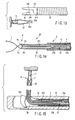
- the clip manipulating device 29 comprises a portion corresponding to a driving wire 30a of the manipulating wire 30 on the handling side and a doubled wire 30c that is connected to the distal end of the driving wire 30a by means of a joint 30b, as shown in FIG. 16. More specifically, in the doubled wire 30c, a turned distal end portion is hitched and connected to an anchor portion 7e of the clip 7, thereby forming a pliable coupling member portion.
- the doubled wire 30c is relatively long.
- the joint 30b is situated behind a position A at a distance L of 30 mm from the distal end of the clip 7, overreaching a range that covers at least a range corresponding to a movable range area that corresponds to the raising device of the endoscope.
- the joint 30b is always situated in a tube sheath 4 without projecting forward from the distal end of the tube sheath 4 or being exposed, as shown in FIGS. 16 and 17.
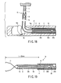
- a clip manipulating device 31 is constructed in like manner, as shown in FIG. 19.
- the clip manipulating device 31 differs from the aforesaid one in that the basal part of the turned distal end portion of the doubled wire 30c is fastened so that the distal end side portion forms a looped portion. This looped portion is hitched to the anchor portion 7e of the clip 7.
- the following is a description of the operation of the device according to the present embodiment.
- the device is used in the steps of procedure shown in FIGS. 16 to 18.
- the present embodiment shares this method of use with the first embodiment.
- the joint 30b of the manipulating wire 30 can never get into the range from the distal end of the clip 7 to the position A at the backward distance of 30 mm from it. Further, it never passes through the range of the backward distance L of 30 mm from the distal end of the clip 7. Therefore, the joint 30b constitutes no hindrance to operation if it is rigid.
- the clip manipulating device 31 shown in FIG. 19 is a modification of the foregoing clip manipulating device 29 according to the sixth embodiment.
- the manipulating method for the disengagement of a clip unit 6 of the clip manipulating device 31 is different from the method for the clip manipulating device 29 according to the sixth embodiment.
- the manipulating wire 30 is advanced to project the doubled wire 30c from the coil sheath 5.
- the distal end of the doubled wire 30c is disengaged from the anchor portion 7e of the clip 7, and the clip unit 6 is confined in the patient's body.
- the joint 30b of the manipulating wire 30 can never get into the range from the distal end of the clip 7 to the position A at the backward distance of 30 mm from it.
- the joint 30b a rigid portion, never passes through the range of the backward distance L of 30 mm from the distal end of the clip 7, so that the same effects of the first embodiment can be obtained.
- a part of the manipulating wire 30 is formed into the thick driving wire 30a, so that the force transmission performance is improved further.
- a clip manipulating device according to a seventh embodiment of the present will be described with reference to FIGS. 21 and 22.
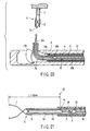
- a clip unit 6 of a clip manipulating device 32 comprises a clip 7, a pliable looped wire 33 for use as a flexible connecting member hitched to the proximal end of the clip 7, and a retainer pipe 8.
- a hook 35 is provided on the distal end of a manipulating wire 34 for use as manipulating means.
- a coupling plate 36 is removably mounted on the hook 35, and the clip unit 6 is coupled to the coupling plate 36 of the manipulating wire 34 by means of the looped wire 33.
- the coupling plate 36 is formed having a J-shaped portion 36a as deformable anchor means on its distal end portion.
- the proximal end portion of the looped wire 33 is hitched to the anchoring J-shaped portion 36a, and the hook 35 is detachably coupled to the hook 35.
- the hook 35 and the coupling plate 36 are situated behind a position A at a backward distance L of 30 mm from the distal end of the clip 7, so that they cannot be projected and exposed through the distal end of the tube sheath 4.
- the clip manipulating device 32 The following is a description of the operation of the clip manipulating device 32 according to the present embodiment. If the manipulating wire 34 is pulled further strongly after the affected region 11 is grasped by means of the clip 7, as shown in FIG. 22, the J-shaped portion 36a of the coupling plate 36 extends. Thereupon, the looped wire 33 is released from the anchored state, so that the clip unit 6 is disengaged. The clip unit 6 is confined in the patient's body.
- the present embodiment shares the effects with the sixth embodiment mentioned before.
- the present invention is not limited to the embodiments described above, and may be applied to any other configurations.
- the coupling means that is detachably coupled to the clip or the clip unit is not less pliable than enough to follow up the shape of the insertion tube. Even when the insertion tube is in the bent state, therefore, the coupling means can be smoothly moved in the insertion tube without hitching with ease.
- the clip or the clip unit is provided with the anchor portion that is released from the manipulating means by means of the driving force of the given or higher value when it is driven by the manipulating means with the driving force. Accordingly, rigid regions on the manipulating means side can be reduced. Even when the insertion tube is in the bent state, therefore, the coupling means can be smoothly moved in the insertion tube without hitching with ease.
- the coupling means that is coupled to the clip or the clip unit and is released from the clip or the clip unit by means of the driving force of the given or higher value when it is driven with the driving force, is flexible. Even when the insertion tube is in the bent state, therefore, the coupling means can be smoothly moved in the insertion tube without hitching with ease.
- the clip or the clip unit 6 is coupled with the flexible joint in the position at the suitable distance from the distal end of the insertion tube. Even when the insertion tube is in the bent state, therefore, any member of the coupling anchor means can be smoothly moved in the insertion tube without hitching with ease.
- the manipulating means that is coupled to the clip or the clip unit in the distal end of the insertion tube can be manipulated securely and quickly.
- the clip or the clip unit is coupled to the manipulating means by means of the flexible connecting member that is coupled to the clip or the clip unit.
- the connecting member and the manipulating means are coupled by means of the anchor means that is located in the position at the suitable distance from the distal end of the insertion tube.
- the anchor portion releases the connecting member and the manipulating means from connection when the manipulating means is driven with the driving force of the given or higher value. Even when the insertion tube is in the bent state, therefore, any member of the coupling anchor means cannot hitch with ease.
Abstract
Description
- The present invention relates to a clip manipulating device or a clip device for an organic tissue in a cavity of a living body or the like as an object of treatment.
- Clip devices that are used in combination with an endoscope to arrest bleeding from a region in the body cavity are described in Jpn. UM Appln. KOKOKU Publication No. 4-26091 and Jpn. Pat. Appln. KOKOKU Publication No. 63-6016.
- In the device described in Jpn. UM Appln. KOKOKU Publication No. 4-26091, a
clip 53 is hitched by means of acoupling plate 54 to ahook 52, which is attached to the distal end of a manipulatingwire 51 that is passed through asheath 50, as shown in FIG. 23. In the device described in Jpn. Pat. Appln. KOKOKU Publication No. 63-6016, on the other hand, a hook that is attached to the distal end of a manipulating wire is hitched directly to a clip. - In either type, a rigid coupling member, such as a hook or a coupling plate, is connected to the distal end of the manipulating wire. The clip that is located at the distal end of the sheath is detachably attached to the rigid coupling member and set in place. The clip can be opened and closed or disengaged by advancing or retreating the manipulating wire.
- The clip device of this type is guided into the body cavity through a channel of an endoscope when it is worked. Usually, it is used in combination with a straight-viewing endoscope. Depending on the region to be treated in the body cavity, however, it sometimes is very hard to carry out treatment operation through the straight-viewing endoscope. In this case, the device is used in combination with a side-viewing endoscope, as shown in FIG. 23.
- A side-viewing
endoscope 56 is furnished with a forceps raisingdevice 57 in the distal end opening of its channel. Theforceps raising device 57 is used to raise aclip device 58 and guide theclip device 58 into the region to be treated in the body cavity. - Thus, in the side-
viewing endoscope 56, theclip device 58 is bent and raised by means of theforceps raising device 57, so that the distal end portion of theclip device 58 is bent particularly deep. - In the clip devices described in Jpn. Pat. Appln. KOKOKU Publication No. 63-6016 and Jpn. UM Appln. KOKOKU Publication No. 4-26091, the clip is attached to the distal end of an insertion tube when it is introduced into the body cavity. Thereafter, the clip is manipulated by means of the manipulating wire, whereby the clip is disengaged from the coupling member of the manipulating wire. In the processes of operation for opening and closing the clip or disengaging the clip from the manipulating wire, the rigid coupling member, e.g., the hook or the coupling plate, on the distal end of the manipulating wire moves together with the manipulating wire in the sheath, and finally moves into the rear part of the sheath.
- If the side-viewing endoscope is used, however, the distal end portion, in particular, of the sheath of the clip device is bent deep and suddenly. Therefore, the hook or the coupling plate, the rigid coupling member, is easily caught by the bent part of the sheath. It is hard for the hook or the coupling plate, the rigid coupling member, moreover, to pass smoothly through the bent part of the sheath. In some cases, therefore, a series of operations from grasping operation to disengaging operation of the clip cannot be carried out securely and smoothly.
- This problem may arise when the device is used in combination with a straight- or oblique-viewing endoscope as well as when it is used in combination with the side-viewing endoscope.
- Some straight- or oblique-viewing endoscopes may be furnished with a forceps raising device. Even in an endoscope that is furnished with no forceps raising device, the sheath may possibly suffer from a bent part when an insertion section itself is curved, for example. In a clip device that uses a thin sheath, in particular, the hook or the coupling plate, the rigid coupling member, is easily caught by a slightly bent part of the sheath, without regard to the type of the endoscope that is used in combination with the device. The rigid coupling member easily fails to pass smoothly through the bent part.
- The object of the present invention is to provide a clip manipulating device or a clip device, in which a clip (including a clip unit) located near the distal end of an insertion tube can be manipulated securely and quickly by means of manipulating means that is coupled to the clip or the clip unit.
- The present invention is a clip manipulating device, in which the distal end portion of a flexible wire, having pliability and movably passed through a flexible insertion tube capable of being inserted into a cavity of a living body, forms a junction which is detachably coupled with a clip located at the distal end portion of the insertion tube. The junction is pliable enough to follow up deformation of the insertion tube.
- The present invention is a clip manipulating device, in which elongate means is passed for advance and retreat through flexible insertion means capable of being inserted into a cavity of a living body. The elongate is detachably coupled to a clip, which is located at the distal end portion of the insertion means, and is not less pliable than enough to follow up deformation of the insertion means.
- The present invention is a clip manipulating device, comprising a manipulating member, which is passed for advance and retreat through a flexible insertion tube capable of being inserted into a cavity of a living body and effects grasping operation and disengaging operation of a clip located at the distal end portion of the insertion tube, and a flexible connecting member, which has one end coupled to the distal end of the manipulating member and the other end detachably coupled to the clip and is pliable enough to follow up deformation of the insertion tube.
- The present invention is a clip manipulating device, in which a coupling member is provided on the distal end of a manipulating member, which is passed for movement through a flexible insertion tube capable of being inserted into a cavity of a living body, and a wire, extending from the clip and pliable enough to follow up deformation of the insertion tube, is coupled to the coupling member.
-
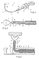
- FIG. 1 is a perspective view of a clip manipulating device according to a first embodiment;
- FIG. 2 is a view showing the distal end portion of the clip manipulating device according to the first embodiment and its surroundings;
- FIG. 3 is a view the clip manipulating device according to the first embodiment in a working state;
- FIG. 4 is a view the clip manipulating device according to the first embodiment in a working state;
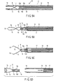
- FIGS. 5A to 5D are views illustrating the action of a clip manipulating device according to a second embodiment in operation;
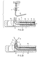
- FIG. 6 is a view showing the distal end portion of a clip manipulating device according to a third embodiment and its surroundings;
- FIG. 7 is a view showing the clip manipulating device according to the third embodiment in a working state;
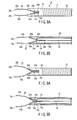
- FIGS. 8A and 8B are views illustrating the distal end portion of a clip manipulating device according to a fourth embodiment and its surroundings;
- FIGS. 9A and 9B are views illustrating the distal end portion of the clip manipulating device according to the fourth embodiment and its surroundings;
- FIG. 10 is a view illustrating the distal end portion of the clip manipulating device according to the fourth embodiment and its surroundings;
- FIG. 11 is a view illustrating the distal end portion of the clip manipulating device according to the fourth embodiment and its surroundings in a working state;
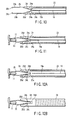
- FIGS. 12A and 12B are views illustrating the distal end portion of the clip manipulating device according to the fourth embodiment and its surroundings in a working state;
- FIG. 13 is a view illustrating the distal end portion of the clip manipulating device according to the fourth embodiment and its surroundings in a working state;
- FIG. 14 is a view showing the distal end portion of a clip manipulating device according to a fifth embodiment and its surroundings;
- FIG. 15 is a view showing the distal end portion of the clip manipulating device according to the fifth embodiment and its surroundings in a working state;
- FIG. 16 is a view showing the distal end portion of a clip manipulating device according to a sixth embodiment and its surroundings;
- FIG. 17 is a view showing the distal end portion of the clip manipulating device according to the sixth embodiment and its surroundings in a working state;
- FIG. 18 is a view showing the distal end portion of the clip manipulating device according to the sixth embodiment and its surroundings in a working state;
- FIG. 19 is a view showing the distal end portion of the clip manipulating device according to the sixth embodiment and its surroundings;
- FIG. 20 is a view showing the distal end portion of the clip manipulating device according to the sixth embodiment and its surroundings in a working state;
- FIG. 21 is a view showing the distal end portion of a clip manipulating device according to a seventh embodiment and its surroundings;
- FIG. 22 is a view showing the distal end portion of the clip manipulating device according to the seventh embodiment and its surroundings in a working state; and
- FIG. 23 is a view showing the distal end portion of a conventional clip device and its surroundings.
-
- A clip manipulating device according to a first embodiment of the present invention will be described with reference to FIGS. 1 to 4.
- As shown in FIG. 1, a
clip manipulating device 1 according to the present embodiment comprises aninsertion section 2 and acontrol section 3. Theinsertion section 2 is formed of aflexible tube sheath 4 of, e.g., resin and acoil sheath 5 as a flexible insertion tube that is passed through thetube sheath 4. Thetube sheath 4 and thecoil sheath 5 are slidable relatively to each other in the longitudinal direction. The proximal end of thecoil sheath 5 is connected to abody 3a of thecontrol section 3. Further, acylindrical stopper 4b that can abut against the distal end of thebody 3a is fixedly fitted on the proximal end portion of thetube sheath 4. - As shown in FIG. 2, a
clip unit 6 is attached to the distal end of thecoil sheath 5. Theclip unit 6 is composed of aclip 7 and aretainer pipe 8. Theclip 7 is formed of a thin stainless-steel strip material that is bent in the middle. This bent part serves as aproximal end portion 7a, and those parts which are continuous with theproximal end portion 7a individually form a pair ofretractable portions 7b that are spaced wider than the inside diameter of theretainer pipe 8. Strip material portions that further extend from theretractable portions 7b are crossed, and the respective one-side parts of two strip material portions that extend from the intersection for a pair ofarm portions 7c, individually. Further, the respective distal end portions of thearm portions 7c are bent toward each other so that the two bent parts serve as nippingportions 7d, individually. The pair ofarm portions 7c are given aptitude for spreading such that theopposed nipping portions 7d are kept wide apart, as shown in FIG. 2. - As shown in FIG. 2, a
hooked anchor portion 7e, which is bent substantially in the shape of a J, is formed protruding backward from the proximal end portion of theclip 7. Theanchor portion 7e constitutes a junction that is detachably coupled to the distal end of a manipulatingwire 9 that is passed through thecoil sheath 5. Theanchor portion 7e is coupled to the distal end of the manipulatingwire 9 for use as manipulating means, which will be mentioned later. When the manipulatingwire 9 is hauled with a driving force of a given or higher value, the substantially J-shapedanchor portion 7e is straightened and released from the manipulatingwire 9 by means of the tractive effort of thewire 9. - As shown in FIG. 2, the manipulating
wire 9 is formed by doubling one flexible wire member, and two wire portions that are returned toward the handling side constitute manipulating means. A looped distal end portion that is formed by bending the one flexible wire member serves as a junction (coupling means). Thus, the looped distal end portion of the manipulatingwire 9 is used as the junction (coupling means) that is anchored to theanchor portion 7e of theclip 7. The looped distal end portion of the manipulatingwire 9 at which the flexible wire member is turned back is directly used to form the junction that is pliable. Since the looped extreme end portion of the manipulatingwire 9 serves as a junction that is to be hitched to theanchor portion 7e, the wire member in the looped distal side part of the manipulatingwire 9 forms a pliable coupling member. This junction has pliability such that thecoil sheath 5 for use as the insertion tube can normally follow up possible deformation, such as flexure or bending. - The
clip 7 is located near the distal end of thecoil sheath 5. The proximal end portion of theclip 7 is fitted into theretainer pipe 8 that abuts against acoil sheath end 5a, and theretainer pipe 8 is loaded with a filler, such as silicone. By doing this, theclip 7 can be tacked to thecoil sheath end 5a. - The proximal end side part of the manipulating
wire 9 passes through thecoil sheath 5 of theinsertion section 2 to reach a longitudinallymovable slider 3b on thecontrol section 3, and is connected to theslider 3b. Thus, there are no rigid portions, including the junction that is anchored to theclip 7, on the rear part of the manipulatingwire 9 that is situated behind theanchor portion 7e of theclip 7 and inside thecoil sheath 5. - The
clip unit 6 is located at the distal end of thecoil sheath 5. By advancing thetube sheath 4 on thecoil sheath 5, theclip unit 6 is encased in the distal end portion of thetube sheath 4. If thetube sheath 4 is retreated from this set state so that thestopper 4b abuts against thebody 3a of thecontrol section 3, as shown in FIG. 2, the respective distal end portions of thecoil sheath 5 and theclip unit 6 project from the distal end of thetube sheath 4 and are exposed to the outside. When thestopper 4b runs against thebody 3a of thecontrol section 3 in this manner, the distal end portion of thecoil sheath 5 forms an exposedportion 5b that projects from the distal end of thetube sheath 4. - The following is a description of the operation of the device according to the first embodiment. First, with the
clip unit 6 encased in thetube sheath 4, theinsertion section 2 of theclip manipulating device 1 is guided into a patient's body through achannel 10a of a side-viewingendoscope 10 shown in FIG. 3. - As shown in FIG. 3, the distal end portion of the
insertion section 2 of theclip manipulating device 1 is projected from theendoscope 10, thetube sheath 4 for use as a manipulating member is retreated, and thestopper 4b is caused to abut against the distal end of thebody 3a of thecontrol section 3. Thereupon, both theclip unit 6 and the exposedportion 5b of thecoil sheath 5 project from the distal end of thetube sheath 4. - In this state, a
forceps raising device 10b of theendoscope 10 is raised, as shown in FIG. 3. Thereupon, the exposedportion 5b of thecoil sheath 5 is intensively bent and raised by means of theforceps raising device 10b, and theclip unit 6 gets into the field of theendoscope 10. The exposedportion 5b of thecoil sheath 5 is long enough to be curved by means of theforceps raising device 10b. Thus, the exposedportion 5b can be securely fixed in its raised state with its middle part kept bent by means of theforceps raising device 10b. - As shown in FIG. 3, the
clip unit 6 is guided to an affectedregion 11 in the patient's body, and operation is carried out to pull theslider 3b of thecontrol section 3 toward the proximal end. By this operation, the manipulatingwire 9 is hauled and retreated toward the proximal end. Thereupon, theretractable portions 7b of theclip 7 are drawn into and squeezed by theretainer pipe 8, and the pair of nippingportions 7d of theclip 7 spread out wide, as shown in FIG. 3. - The pair of nipping
portions 7d of theclip 7 in the spread state are pressed against the affectedregion 11, and the manipulatingwire 9 is hauled and retreated by pulling theslider 3b toward the proximal end as it is. Thereupon, the respective proximal end portions of thearm portions 7c of theclip 7 are drawn into theretainer pipe 8, and thearm portions 7c of theclip 7 are closed to grasp the affectedregion 11, as shown in FIG. 4. - With the affected
region 11 nipped by means of theclip 7 in this manner, theslider 3b is pulled toward the proximal end, and the manipulatingwire 9 is hauled and retreated. Since the tractive effort to retreat the manipulatingwire 9 is greater than before, theanchor portion 7e of theclip 7, having so far been engaged by the distal end of the manipulatingwire 9, is deformed and elongated. Thereupon, the manipulatingwire 9 is disengaged from theanchor portion 7e, as shown in FIG. 4. Theclip 7 and the manipulatingwire 9 are disengaged from each other, whereupon theclip unit 6 is disengaged and released from the manipulatingwire 9. As shown in FIG. 4, theclip unit 6 is confined in the patient's body without ceasing to nip the affectedregion 11. - In a final stage for the
clip unit 6 to leave the manipulatingwire 9, theanchor portion 7e of theclip 7 elongates substantially straight, as shown in FIG. 4. However, the distal end of theanchor portion 7e never projects outward from the end of theretainer pipe 8. Therefore, the body wall or the like cannot be damaged by the hookedanchor portion 7e that is elongated after the disengagement. - In the present embodiment, the whole manipulating
wire 9 is pliable, including the distal junction formed of that part of the wire which is situated behind theanchor portion 7e of theclip 7, and includes no rigid portions. In a series of processes of clip manipulation by pulling the manipulatingwire 9 toward the handling side, therefore, the wire can be smoothly moved in thecoil sheath 5 without being easily caught by that part of thecoil sheath 5 which is bent by means of theforceps raising device 10b. The manipulatingwire 9 can be quickly advanced and retreated in thecoil sheath 5 to ensure smooth manipulation. If thecoil sheath 5 is deeply bent by means of theforceps raising device 10b in the side-viewingendoscope 10, in particular, the movement in thecoil sheath 5 cannot be hindered. Thus, theclip manipulating device 1 can be operated securely and quickly even in the side-viewingendoscope 10. - In the present embodiment of the invention, the coupling means that is detachably coupled to the clip or the clip unit is not less pliable than enough to follow up the shape of the insertion tube. Even when the insertion tube is in a bent state, therefore, the coupling means cannot be easily caught in the middle of the interior of the insertion tube, so that it can be smoothly moved in the insertion tube.
- Further, the clip or the clip unit is provided with the anchor portion that is released from the manipulating means of the manipulating
wire 9 by means of the tractive effort of the given or higher value when it is hauled by the manipulating means with the tractive effort. Accordingly, rigid regions on the manipulating means side can be eliminated or reduced. Even when the insertion tube is in the bent state, therefore, the coupling means can be smoothly moved in the insertion tube without hitching with ease. - A clip manipulating device according to a second embodiment of the present invention will be described with reference to FIGS. 5A to 5D.
- A
clip manipulating device 12 according to the present embodiment has the following construction. In aninsertion section 2 of theclip manipulating device 12, a sheath member that is equivalent to thetube sheath 4 forms acoil sheath 13. A cylindricaldistal tip 14, which has a diameter smaller than the inside diameter of thecoil sheath 13, is coaxially mounted and fixed on the distal end of thecoil sheath 13. - A manipulating
wire 15 to be coupled to aclip unit 6 is passed through a sheath-shaped push member 17 (mentioned later) in thecoil sheath 13 as it is guided to the handling side through thecoil sheath 13. - The manipulating
wire 15 is formed by turning a pliable wire in the middle, and the turned distal side part forms a pliable junction (coupling means). Ananchor portion 7e of theclip unit 6 is removably anchored to a loopedportion 15a at the extreme end. - The
clip unit 6 is composed of aclip 7, which is formed in the same manner as the one according to the foregoing first embodiment, and aclamp ring 16 formed of resin or metal having satisfactory strength and elasticity. Theclamp ring 16 has, on its outer peripheral region, a pair of or a plurality ofcollapsible blades clamp ring 16. - The
anchor portion 7e for use as a wire connecting portion is provided on the rear end of theclip 7. The looped portion (junction) 15a of the manipulatingwire 15 is coupled to theanchor portion 7e for detachable engagement. Theanchor portion 7e, like the one according to the foregoing first embodiment, is configured to be detachably coupled with the looped distal end portion of the manipulatingwire 9 that is passed through thecoil sheath 5. Theanchor portion 7e is elongated to release the manipulatingwire 9 for use as manipulating means (mentioned later) by means of a tractive effort of a given or higher value when the manipulatingwire 9 is hauled with the tractive effort. - Further, the
coil sheath 13 has therein theflexible push member 17 that surrounds the manipulatingwire 15. Thepush member 17 is fixed to the manipulatingwire 15 on the handling side. - In the present embodiment, that part of the manipulating
wire 15 which is also situated behind theanchor portion 7e of theclip 7 includes no rigid portions. The present embodiment shares other configurations with the first embodiment mentioned before. - The following is a description of the operation of the device according to the present embodiment. First, the
blades clamp ring 16 are folded, and theclip unit 6 is encased in thecoil sheath 13, as shown in FIG. 5A. With theclip unit 6 encased in this manner, theinsertion section 2 of theclip manipulating device 1 is introduced into the body cavity through the channel of the endoscope. - Then, the
push member 17 is advanced by means of theslider 3b of thecontrol section 3 so that theclip unit 6 is temporarily projected from the distal end of thecoil sheath 13, as shown in FIG. 5B. Thereupon, theblades clamp ring 16, having so far been folded, expand into their original shape. - If the manipulating
wire 15, along with thecoil sheath 13, is pulled slightly to retreat theclamp ring 16, as shown in FIG. 5C, theblades distal tip 14 and are prevented from retreating further. Thecoil sheath 13 is retreated leaving thedistal tip 14. - The
coil sheath 13, receded from thedistal tip 14, is suitably raised by means of the forceps raising device of the endoscope, and theclip 7 is guided toward the affectedregion 11 in the patient's body. With theclip 7 pressed against the affectedregion 11, theslider 3b is pulled toward the handling side, and the manipulatingwire 15 is hauled. Thereupon,retractable portions 7b of theclip 7 are drawn into theclamp ring 16, and theretractable portions 7b are squeezed so that theclip 7 spreads, as shown in FIG. 5C. - If the manipulating
wire 15 is further retreated so that the respective proximal portions ofarm portions 7c of theclip 7 are drawn into theclamp ring 16, theclip 7 can be closed to grasp the affectedregion 11. If the manipulatingwire 15 is hauled and retreated with the affectedregion 11 nipped by means of theclip 7, theanchor portion 7e of theclip 7. is deformed and elongated straight so that it is disengaged from the junction at the distal end of the manipulatingwire 15, as shown in FIG. 5D, whereupon theclip unit 6 leaves theinsertion section 2. As shown in FIG. 5D, theclip 7 is confined in the patient's body without ceasing to nip the affectedregion 11. - According to the present embodiment, as described above, projecting the
clip unit 6 from thecoil sheath 13 and manipulating the clip can be carried out by means of theslider 3b of thecontrol section 3. Thus, the present embodiment has the effect that the manipulation is easy, besides the same effects of the first embodiment. - A clip manipulating device according to a third embodiment of the present invention will be described with reference to FIGS. 6 and 7.
- A
clip manipulating device 18 for organic tissue according to the present embodiment is constructed in the following manner. Aninsertion section 2 of theclip manipulating device 18 is constructed in the same manner as the one according to the first embodiment mentioned before. As shown in FIG. 6, a manipulatingwire 19 is passed through acoil sheath 5 of theinsertion section 2. Aclip unit 6 is formed of aclip 7 and aretainer pipe 20 having a small-diameter portion 20a, which will be mentioned later. - The
clip 7 is constructed substantially in the same manner as the one according to the first embodiment mentioned before. In the present embodiment, however, it is not provided with theanchor portion 7e, and a looped portion at aproximal end portion 7a of theclip 7 is formed as an anchor portion for wire connection. The distal end wire portion of the manipulatingwire 19 is passed through and anchored to the looped portion. - As shown in FIG. 6, the distal end portion of the manipulating
wire 19 is formed by passing one pliable wire member through the looped portion at theproximal end portion 7a of theclip 7 and turning it backward, and then intertwining the backwardly turned wire portion with the remaining original part of the manipulatingwire 19, thereby forming a strandedportion 19a for connection. The manipulatingwire 19 is the weakest part of the wire member. - With this construction, the pliable coupling member portion can be formed having no rigid portions on that part of the manipulating
wire 19 which is situated behind theproximal end portion 7a of theclip 7. - A cylindrical
distal tip 21 is provided on the distal end of thecoil sheath 5. The distal end portion of thedistal tip 21 is fitted on the small-diameter portion 20a on the outer periphery of the rear end portion of theretainer pipe 20. The rear end portion of thedistal tip 21 is fitted and mounted on the outer periphery of the distal end portion of thecoil sheath 5. The present embodiment shares other configurations with the first embodiment mentioned before. - The device according to the present embodiment differs from the aforementioned one according to the first embodiment in the mode of disengagement of the
clip unit 6. If the manipulatingwire 19 is hauled to close theclip 7 and hauled further strongly with the affectedregion 11 grasped, according to the present embodiment, the wire portion corresponding to the stranded portion (weak point) 19a is loosened so that the manipulatingwire 19 is disengaged from theproximal end portion 7a of theclip 7. Thereupon, theclip unit 6 comes off the manipulatingwire 19. The manipulatingwire 19 constitutes a junction that leaves theclip 7 as the strandedportion 19a is loosened with a tractive effort of a given value not lower than enough to loosen the wire portion corresponding to the strandedportion 19a when the junction is hauled with that tractive effort. The present embodiment substantially shares other configurations with the first embodiment mentioned before. - According to the present embodiment, the device can be used in the same manner as in the first embodiment with the same functions and effects. According to the present embodiment, which enjoys the same effects of the first embodiment, moreover, the
clip 7 is not provided with any anchor portion that extends backward, so that theretainer pipe 20 need not be lengthened to cover the backwardly extending anchor portion. Theretainer pipe 20 can be shortened correspondingly. Since thedistal tip 21 on the distal end of thecoil sheath 5 is fitted on theretainer pipe 20, moreover, an effect can be obtained that theclip unit 6 never tilts. - A clip manipulating device according to a fourth embodiment of the present invention will be described with reference to FIGS. 8A to 13.
- A
clip manipulating device 22 for organic tissue according to the present embodiment is constructed in the following manner. As shown in FIG. 8A, aninsertion section 2 is formed of acoil sheath 23, and adistal tip 24 is fixedly attached to the distal end of thecoil sheath 23. Defined in thedistal tip 24 is a clip setting portion that detachably stores the clip and controls the clip in open-close action and plastic deformation. As shown in FIG. 8B, the inner wall portion of thedistal tip 24 is formed having a pair ofslope portions 24a, which are axisymmetrically located above and below so that they are more distant from each other on the distal end side. The pair ofslope portions 24a range from the distal end of thedistal tip 24 to the middle. As shown in FIG. 8A, a large-diameter hole 24b that is continuous with the respective rear end edges of theslope portions 24a is defined in that part which is situated on the rear end side of the rear end edges of theslope portions 24a. A pair ofprojections 24c are formed individually on the respective rear ends of theslope portions 24a. Theprojections 24c are formed by utilizing projecting end edges on the boundary between theslope portions 24a and the large-diameter hole 24b. - As shown in FIG. 8A, the
distal tip 24 is provided with aslit 24d that opens in one side face thereof. Aclip 25 can be attached to and detached from theslope portions 24a via the region corresponding to thedistal tip 24 by utilizing theslit 24d. As shown in FIG. 9A, moreover, theslit 24d can be utilized for the recognition of the loading operation or set state of theclip 25 and the like. - As shown in FIG. 8A, the
clip 25 is formed by doubling a thin stainless-steel strip material that is bent in the middle. This bent part serves as aproximal end portion 25a andarm portions 25b extend from theproximal end portion 25a. The respective distal end portions of thearm portions 25b are bent toward each other so that they serve as nippingportions 25c, individually. Theproximal end portion 25a of theclip 25 is given aptitude for spreading such that the nippingportions 25c can spread wider than in the state shown in FIG. 9A. As shown in FIG. 8A, recesses 25d are formed individually in those parts of thearm portions 25b of theclip 25 which are situated near theproximal end portion 25a. Theprojections 24c can be fitted in and engage therecesses 25d, individually. - A manipulating
wire 19, like the aforesaid one according to the third embodiment, has a pliable junction (coupling means) on its wire distal end side part. More specifically, the wire distal end side part of the manipulatingwire 19 is passed through a looped portion of theproximal end portion 25a of theclip 25 and doubled. The turned wire portion is led backward and intertwined and joined with the remaining original wire portion, whereupon a strandedportion 19a is formed. Also in the present embodiment, therefore, there are no rigid portions on that part of the manipulatingwire 19 which is situated behind theproximal end portion 25a of theclip 25. - The
coil sheath 23 and the manipulatingwire 19 are connected to thebody 3a of thecontrol section 3 and theslider 3b, respectively. - The following is a description of the operation of the device according to the present embodiment. First, the respective proximal end side parts of the
arm portions 25b of theclip 25 are encased in thedistal tip 24, as shown in FIGS. 8A and 8B. In this state, theinsertion section 2 of theclip manipulating device 12 is guided into the body cavity through the channel of the endoscope. Theslider 3b of thecontrol section 3 is advanced a little way, and the manipulatingwire 19 is loosened to advance theclip 25 for a short distance. Thereupon, thearm portions 25b are spread by the aptitude of theclip 25 for spreading, as shown in FIGS. 9A and 9B. If theslider 3b is pulled toward the handling side, in contrast with this, thearm portions 25b of theclip 25 get into thedistal tip 24, and the respective outer surfaces of thearm portions 25b come individually into contact with theslope portions 24a. Thereupon, thearm portions 25b of theclip 25 are closed against the aptitude for spreading (see FIGS. 10 and 11). - Thereupon, the forceps raising device of the endoscope is manipulated so that the
clip 25 is guided into the affectedregion 11 in the body cavity, as shown in FIG. 11. Then, the manipulatingwire 19 is advanced to spread and press theclip 25 against the affectedregion 11. The manipulatingwire 19 is pulled by means of the slider with theclip 25 pressed against the affectedregion 11. Thereupon, theclip 25 is closed to grasp the affectedregion 11, as shown in FIG. 11. As this is done, theproximal end portion 25a of theclip 25 is plastically deformed by theprojections 24c of thedistal tip 24. After theprojections 24c are cleared, theprojections 24c are fitted individually into therecesses 25d of theclip 25, thereby anchoring theclip 25. - If the manipulating
wire 19 is further retreated in this anchored state, the strandedportion 19a loosens, as shown in FIG. 12. The manipulatingwire 19 is disengaged from theproximal end portion 25a of theclip 25. - The
clip 25 is allowed to be disengaged sideways from theslit 24d of thedistal tip 24. As shown in FIG. 13, theclip 25 can be disengaged from thedistal tip 24 and confined in the patient's body without ceasing to nip the affectedregion 11. - The same effects of the first embodiment mentioned before can be obtained according to the present embodiment. Since the
retainer pipe 8 and the like for theclip 25 are omitted, the present embodiment also has an effect that the device requires fewer components and can be manufactured at low cost. Further, manipulation can be simplified. Since thearm portions 25b of theclip 25 is fitted in thedistal tip 24, moreover, dislocation between the unit of theclip 25 and thecoil sheath 13 can be prevented when the forceps is raised, for example. - A clip manipulating device according to a fifth embodiment of the present will be described with reference to FIGS. 14 and 15.
- A
clip manipulating device 26 for organic tissue according to the present embodiment differs from the aforementioned one according to the third embodiment in the configuration of a manipulatingwire 27. The manipulatingwire 27 of the present embodiment comprises adriving wire 27a, which is situated on the handling side, and a doubledthread 27c for use as a junction (coupling means) that is connected to the distal end of drivingwire 27a by means of a joint 27b. A looped distal end portion of the doubledthread 27c serves as a junction that is anchored to aclip 7. That part (junction) of thethread 27c which is to be turned is passed through a proximal end portion (anchor portion) 7a of theclip 7 and anchored. When subjected to a given or heavier load, the turned wire portion of thethread 27c forms a weak point and snaps, whereupon theclip 7 is released. The joint 27b is situated behind an exposedportion 5b of acoil sheath 5. Thus, thedriving wire 27a for use as the manipulating means couples thethread 27c as a flexible coupling member to theclip 7, and the joint 27b is located in a position at a suitable distance from the distal end of thecoil sheath 5. - In order to bunch the thread elements on the doubled
thread 27c or for other purposes, a very small rigid portion may be provided using an adhesive material or the like. Aretainer pipe 28, which is similar to the one according to the first embodiment, abuts against the distal end of thecoil sheath 5. The present embodiment shares other configurations with the first embodiment mentioned before. - The following is a description of the operation of the device according to the present embodiment. The present embodiment differs from the aforementioned third embodiment in the process of disengagement of the
clip unit 6. According to the present embodiment, thedriving wire 27a is hauled to close theclip 7, whereupon the affectedregion 11 is grasped. If thedriving wire 27a is further hauled in this grasping state, thethread 27c is broken by a tractive effort that exceeds a given value and disengaged from theproximal end portion 7a of theclip 7. Theclip unit 6 comes off the manipulatingwire 27. The present embodiment shares the effects with the third embodiment mentioned before. Further, a side-viewing scope may be used to cope with a rigid joint, if any. If there is a rigid joint, moreover, the forceps raising device can be activated by means of the side-viewing scope to ensure smooth use. - The disengagement means according to the present embodiment that allows the wire portion to snap and release the
clip 7 is also applicable to the first embodiment mentioned before. Also available is an arrangement such that the wire portion of the strandedportion 19a according to the foregoing third embodiment loosens so that the manipulatingwire 19 is disengaged from theproximal end portion 7a of theclip 7. - Clip manipulating devices according to a sixth embodiment of the present will be described with reference to FIGS. 16 to 20.
-
Clip manipulating devices wire 30 and aclip 7. - First, the
clip manipulating device 29 comprises a portion corresponding to adriving wire 30a of the manipulatingwire 30 on the handling side and a doubledwire 30c that is connected to the distal end of thedriving wire 30a by means of a joint 30b, as shown in FIG. 16. More specifically, in the doubledwire 30c, a turned distal end portion is hitched and connected to ananchor portion 7e of theclip 7, thereby forming a pliable coupling member portion. The doubledwire 30c is relatively long. Accordingly, the joint 30b is situated behind a position A at a distance L of 30 mm from the distal end of theclip 7, overreaching a range that covers at least a range corresponding to a movable range area that corresponds to the raising device of the endoscope. Thus, the joint 30b is always situated in atube sheath 4 without projecting forward from the distal end of thetube sheath 4 or being exposed, as shown in FIGS. 16 and 17. - A
clip manipulating device 31 is constructed in like manner, as shown in FIG. 19. Theclip manipulating device 31 differs from the aforesaid one in that the basal part of the turned distal end portion of the doubledwire 30c is fastened so that the distal end side portion forms a looped portion. This looped portion is hitched to theanchor portion 7e of theclip 7. - The following is a description of the operation of the device according to the present embodiment. The device is used in the steps of procedure shown in FIGS. 16 to 18. The present embodiment shares this method of use with the first embodiment. In this process, however, the joint 30b of the manipulating
wire 30 can never get into the range from the distal end of theclip 7 to the position A at the backward distance of 30 mm from it. Further, it never passes through the range of the backward distance L of 30 mm from the distal end of theclip 7. Therefore, the joint 30b constitutes no hindrance to operation if it is rigid. In other words, there is no possibility of the rigid joint 30b passing through thecoil sheath 5 that is bent by means of theforceps raising device 10b, so that the movement of the manipulatingwire 30 cannot be hindered. Since a part (handling side portion) of the manipulatingwire 30 can be formed into thethick driving wire 30a, moreover, the performance of the manipulatingwire 30 to transmit force is improved. - The
clip manipulating device 31 shown in FIG. 19 is a modification of the foregoingclip manipulating device 29 according to the sixth embodiment. The manipulating method for the disengagement of aclip unit 6 of theclip manipulating device 31 is different from the method for theclip manipulating device 29 according to the sixth embodiment. After the affectedregion 11 is grasped by theclip 7, as shown in FIG. 20, the manipulatingwire 30 is advanced to project the doubledwire 30c from thecoil sheath 5. The distal end of the doubledwire 30c is disengaged from theanchor portion 7e of theclip 7, and theclip unit 6 is confined in the patient's body. - Also in this process of disengaging operation, the joint 30b of the manipulating
wire 30 can never get into the range from the distal end of theclip 7 to the position A at the backward distance of 30 mm from it. - According to the present embodiment, the joint 30b, a rigid portion, never passes through the range of the backward distance L of 30 mm from the distal end of the
clip 7, so that the same effects of the first embodiment can be obtained. Besides, a part of the manipulatingwire 30 is formed into thethick driving wire 30a, so that the force transmission performance is improved further. - A clip manipulating device according to a seventh embodiment of the present will be described with reference to FIGS. 21 and 22.
- As shown in FIG. 21, a
clip unit 6 of aclip manipulating device 32 according to the present embodiment comprises aclip 7, a pliable loopedwire 33 for use as a flexible connecting member hitched to the proximal end of theclip 7, and aretainer pipe 8. Ahook 35 is provided on the distal end of a manipulatingwire 34 for use as manipulating means. Acoupling plate 36 is removably mounted on thehook 35, and theclip unit 6 is coupled to thecoupling plate 36 of the manipulatingwire 34 by means of the loopedwire 33. Thecoupling plate 36 is formed having a J-shapedportion 36a as deformable anchor means on its distal end portion. The proximal end portion of the loopedwire 33 is hitched to the anchoring J-shapedportion 36a, and thehook 35 is detachably coupled to thehook 35. As in the aforementioned case, thehook 35 and thecoupling plate 36 are situated behind a position A at a backward distance L of 30 mm from the distal end of theclip 7, so that they cannot be projected and exposed through the distal end of thetube sheath 4. - The following is a description of the operation of the
clip manipulating device 32 according to the present embodiment. If the manipulatingwire 34 is pulled further strongly after the affectedregion 11 is grasped by means of theclip 7, as shown in FIG. 22, the J-shapedportion 36a of thecoupling plate 36 extends. Thereupon, the loopedwire 33 is released from the anchored state, so that theclip unit 6 is disengaged. Theclip unit 6 is confined in the patient's body. The present embodiment shares the effects with the sixth embodiment mentioned before. - The present invention is not limited to the embodiments described above, and may be applied to any other configurations.
- In the present invention, the coupling means that is detachably coupled to the clip or the clip unit is not less pliable than enough to follow up the shape of the insertion tube. Even when the insertion tube is in the bent state, therefore, the coupling means can be smoothly moved in the insertion tube without hitching with ease.
- In the present invention, the clip or the clip unit is provided with the anchor portion that is released from the manipulating means by means of the driving force of the given or higher value when it is driven by the manipulating means with the driving force. Accordingly, rigid regions on the manipulating means side can be reduced. Even when the insertion tube is in the bent state, therefore, the coupling means can be smoothly moved in the insertion tube without hitching with ease.
- In the present invention, moreover, the coupling means, that is coupled to the clip or the clip unit and is released from the clip or the clip unit by means of the driving force of the given or higher value when it is driven with the driving force, is flexible. Even when the insertion tube is in the bent state, therefore, the coupling means can be smoothly moved in the insertion tube without hitching with ease.
- In the present invention, the clip or the
clip unit 6 is coupled with the flexible joint in the position at the suitable distance from the distal end of the insertion tube. Even when the insertion tube is in the bent state, therefore, any member of the coupling anchor means can be smoothly moved in the insertion tube without hitching with ease. - According to the present invention, the manipulating means that is coupled to the clip or the clip unit in the distal end of the insertion tube can be manipulated securely and quickly.
- In the present invention, the clip or the clip unit is coupled to the manipulating means by means of the flexible connecting member that is coupled to the clip or the clip unit. The connecting member and the manipulating means are coupled by means of the anchor means that is located in the position at the suitable distance from the distal end of the insertion tube. The anchor portion releases the connecting member and the manipulating means from connection when the manipulating means is driven with the driving force of the given or higher value. Even when the insertion tube is in the bent state, therefore, any member of the coupling anchor means cannot hitch with ease.
Claims (17)
- A clip manipulating device comprising:a flexible insertion tube (5) capable of being inserted into a cavity of a living body;a flexible wire (9) having pliability and movably passed through the insertion tube (5);a junction provided on the distal end portion of the wire (9), detachably coupled with a clip (7) located at the distal end portion of the insertion tube (5), and pliable enough to follow up deformation of the insertion tube (5).
- A clip manipulating device according to claim 1, wherein the junction has a looped portion formed by turning the wire (9), the looped being coupled with the clip (7).
- A clip manipulating device according to claim 1, wherein the wire (9) has a turn portion coupled to the clip (7) and a weak portion formed of at least parts of doubled wire portions on two opposite sides and intertwined so as to loosen when the wire (9) is hauled with a tractive effort great enough to leave the clip (7).
- A clip manipulating device according to claim 1, wherein the junction has a weak portion which breaks when the wire (9) is hauled with a tractive effort great enough to leave the clip (7).
- A clip manipulating device comprising:a flexible insertion tube (5) capable of being inserted into a cavity of a living body;a flexible wire (9) having pliability and movably passed through the insertion tube (5);a clip (7) located at the distal end portion of the insertion tube (5) and having a hook (7e); anda junction provided on the distal end portion of the wire (9), detachably coupled with the hook (7e) of the clip (7), and pliable enough to follow up deformation of the insertion tube (5).
- A clip manipulating device according to claim 5, wherein the clip (7) is provided with a clip retainer pipe (8) which covers the proximal end portion of the clip (7) when the wire (9) is hauled, whereby the clip (7) is manipulated, the retainer pipe (8) covering the hook (7e) when the hook (7e) is deformed so that the hook (7e) is disengaged from the wire (9).
- A clip manipulating device according to claim 1, which comprises a clip setting portion (24) which is provided on the distal end of the insertion tube (5) detachably stores the clip (7), and controls the clip (7) in open-close action and plastic deformation as the wire (9) is manipulated.
- A clip manipulating device according to claim 7, wherein the clip setting portion (24) has a slit (24d) through which the clip (7) gets away after the clip (7) is plastically deformed.
- A clip manipulating device comprising:flexible insertion means (5) capable of being inserted into a cavity of a living body; andelongate means which is passed through the insertion means (5) for advance and retreat, can move with respect to the insertion means (5) so as to be detachably coupled to a clip (7) located at the distal end portion of the insertion means (5), is not less pliable than enough to follow up deformation of the insertion means (5), and effects grasping operation and disengaging operation of the clip (7).
- A clip manipulating device according to claim 9, wherein the elongate means has a flexible wire (9).
- A clip manipulating device comprising:a flexible insertion tube (5) capable of being inserted into a cavity of a living body;a manipulating member (27a) which is passed through the insertion tube (5) for advance and retreat and moves with respect to the insertion tube (5), thereby effecting grasping operation and disengaging operation of a clip (7) located at the distal end portion of the insertion tube (5); anda flexible connecting member (27b) having one end and the other end, the one end being coupled to the distal end of the manipulating member (27a) and the other end detachably coupled to the clip (7), and pliable enough to follow up deformation of the insertion tube (5).
- A clip manipulating device according to claim 11, wherein the connecting member (27b) has a flexible wire and a junction provided on the distal end portion of the wire, detachably coupled to the clip (7), and pliable enough to follow up deformation of the insertion tube (5).
- A clip manipulating device according to claim 12, wherein the junction is formed of the wire and has a weak portion at which the wire breaks when the manipulating member (27a) is hauled with a tractive effort great enough to leave the clip (7).
- A clip manipulating device according to claim 12, wherein the wire has a turn portion coupled to the clip (7) and a weak portion formed of at least parts of doubled wire portions on two opposite sides and intertwined so as to loosen when the manipulating member (27a) is hauled.
- A clip manipulating device comprising:a flexible insertion tube (5) capable of being inserted into a cavity of a living body;a manipulating member (27a) which is passed through the insertion tube (5) for movement and is moved with respect to the insertion tube (5), thereby effecting gasping operation and disengaging operation of a clip (7) located at the distal end portion of the insertion means (5); anda coupling member (27b) which is provided on the distal end of the manipulating member (27a), is coupled to a wire extending from the clip (7) and pliable enough to follow up deformation of the insertion tube (5), effects grasping operation of the clip (7), and can leave the clip (7) when the manipulating member (27a) is hauled with a tractive effort great enough to leave the clip (7).
- A clip manipulating device according to claim 1, which comprises a flexible tube sheath (4) penetrated by the insertion tube (5) for advance and retreat, the tube sheath (4) being capable of storing the clip (7) located at the distal end portion of the insertion tube (5).
- A clip manipulating device according to claim 16, wherein that part of the insertion tube (5) which is situated behind the clip (7) and exposed from the distal end of the tube sheath (4) when the clip (7) projects from the tube sheath (4) forms a curvedly raised portion.
Applications Claiming Priority (3)
| Application Number | Priority Date | Filing Date | Title |
|---|---|---|---|
| JP2002211371 | 2002-07-19 | ||
| JP2002211371A JP4109030B2 (en) | 2002-07-19 | 2002-07-19 | Biological tissue clip device |
| PCT/JP2003/009048 WO2004008975A1 (en) | 2002-07-19 | 2003-07-16 | Clip operation device |
Publications (3)
| Publication Number | Publication Date |
|---|---|
| EP1523946A1 true EP1523946A1 (en) | 2005-04-20 |
| EP1523946A4 EP1523946A4 (en) | 2006-01-04 |
| EP1523946B1 EP1523946B1 (en) | 2008-12-17 |
Family
ID=30767770
Family Applications (1)
| Application Number | Title | Priority Date | Filing Date |
|---|---|---|---|
| EP03741426A Expired - Fee Related EP1523946B1 (en) | 2002-07-19 | 2003-07-16 | Clip operation device |
Country Status (5)
| Country | Link |
|---|---|
| US (1) | US20040176784A1 (en) |
| EP (1) | EP1523946B1 (en) |
| JP (1) | JP4109030B2 (en) |
| DE (1) | DE60325365D1 (en) |
| WO (1) | WO2004008975A1 (en) |
Cited By (1)
| Publication number | Priority date | Publication date | Assignee | Title |
|---|---|---|---|---|
| EP1882451A2 (en) | 2006-07-25 | 2008-01-30 | Olympus Medical Systems Corp. | Clip apparatus for ligaturing living tissue |
Families Citing this family (157)
| Publication number | Priority date | Publication date | Assignee | Title |
|---|---|---|---|---|
| US7491232B2 (en) | 1998-09-18 | 2009-02-17 | Aptus Endosystems, Inc. | Catheter-based fastener implantation apparatus and methods with implantation force resolution |
| US7637905B2 (en) | 2003-01-15 | 2009-12-29 | Usgi Medical, Inc. | Endoluminal tool deployment system |
| US7618426B2 (en) | 2002-12-11 | 2009-11-17 | Usgi Medical, Inc. | Apparatus and methods for forming gastrointestinal tissue approximations |
| US7416554B2 (en) | 2002-12-11 | 2008-08-26 | Usgi Medical Inc | Apparatus and methods for forming and securing gastrointestinal tissue folds |
| US8574243B2 (en) | 1999-06-25 | 2013-11-05 | Usgi Medical, Inc. | Apparatus and methods for forming and securing gastrointestinal tissue folds |
| US8231639B2 (en) | 2001-11-28 | 2012-07-31 | Aptus Endosystems, Inc. | Systems and methods for attaching a prosthesis within a body lumen or hollow organ |
| US20070073389A1 (en) | 2001-11-28 | 2007-03-29 | Aptus Endosystems, Inc. | Endovascular aneurysm devices, systems, and methods |
| US20050070992A1 (en) | 2001-11-28 | 2005-03-31 | Aptus Endosystems, Inc. | Prosthesis systems and methods sized and configured for the receipt and retention of fasteners |
| US9320503B2 (en) | 2001-11-28 | 2016-04-26 | Medtronic Vascular, Inc. | Devices, system, and methods for guiding an operative tool into an interior body region |
| JP4405262B2 (en) | 2001-11-28 | 2010-01-27 | アプタス エンドシステムズ, インコーポレイテッド | Intravascular aneurysm repair system |
| US20050177180A1 (en) | 2001-11-28 | 2005-08-11 | Aptus Endosystems, Inc. | Devices, systems, and methods for supporting tissue and/or structures within a hollow body organ |
| DE60318595T2 (en) * | 2002-08-01 | 2009-01-08 | James E. Birmingham Selis | biopsy devices |
| US7942898B2 (en) | 2002-12-11 | 2011-05-17 | Usgi Medical, Inc. | Delivery systems and methods for gastric reduction |
| US7942884B2 (en) | 2002-12-11 | 2011-05-17 | Usgi Medical, Inc. | Methods for reduction of a gastric lumen |
| US8216252B2 (en) | 2004-05-07 | 2012-07-10 | Usgi Medical, Inc. | Tissue manipulation and securement system |
| US7347863B2 (en) | 2004-05-07 | 2008-03-25 | Usgi Medical, Inc. | Apparatus and methods for manipulating and securing tissue |
| US20050251189A1 (en) | 2004-05-07 | 2005-11-10 | Usgi Medical Inc. | Multi-position tissue manipulation assembly |
| US7361180B2 (en) | 2004-05-07 | 2008-04-22 | Usgi Medical, Inc. | Apparatus for manipulating and securing tissue |
| GB0402796D0 (en) * | 2004-02-09 | 2004-03-10 | Anson Medical Ltd | An endoluminal surgical delivery system |
| US7703459B2 (en) | 2004-03-09 | 2010-04-27 | Usgi Medical, Inc. | Apparatus and methods for mapping out endoluminal gastrointestinal surgery |
| US7230368B2 (en) | 2004-04-20 | 2007-06-12 | Visualsonics Inc. | Arrayed ultrasonic transducer |
| US7736378B2 (en) | 2004-05-07 | 2010-06-15 | Usgi Medical, Inc. | Apparatus and methods for positioning and securing anchors |
| US8257394B2 (en) | 2004-05-07 | 2012-09-04 | Usgi Medical, Inc. | Apparatus and methods for positioning and securing anchors |
| US8444657B2 (en) | 2004-05-07 | 2013-05-21 | Usgi Medical, Inc. | Apparatus and methods for rapid deployment of tissue anchors |
| US7736374B2 (en) | 2004-05-07 | 2010-06-15 | Usgi Medical, Inc. | Tissue manipulation and securement system |
| US7390329B2 (en) * | 2004-05-07 | 2008-06-24 | Usgi Medical, Inc. | Methods for grasping and cinching tissue anchors |
| US7918869B2 (en) | 2004-05-07 | 2011-04-05 | Usgi Medical, Inc. | Methods and apparatus for performing endoluminal gastroplasty |
| US8206417B2 (en) | 2004-06-09 | 2012-06-26 | Usgi Medical Inc. | Apparatus and methods for optimizing anchoring force |
| US7736379B2 (en) | 2004-06-09 | 2010-06-15 | Usgi Medical, Inc. | Compressible tissue anchor assemblies |
| US7678135B2 (en) | 2004-06-09 | 2010-03-16 | Usgi Medical, Inc. | Compressible tissue anchor assemblies |
| US7695493B2 (en) | 2004-06-09 | 2010-04-13 | Usgi Medical, Inc. | System for optimizing anchoring force |
| US8075568B2 (en) | 2004-06-11 | 2011-12-13 | Selis James E | Biopsy devices and methods |
| US8216255B2 (en) * | 2004-06-14 | 2012-07-10 | Ethicon Endo-Surgery, Inc. | Endoscopic clip applier actuator |
| EP2641549B1 (en) | 2004-10-08 | 2015-08-12 | Covidien LP | An endoscopic surgical clip applier |
| JP4783372B2 (en) | 2004-10-08 | 2011-09-28 | タイコ ヘルスケア グループ エルピー | Device for applying a surgical clip |
| US9763668B2 (en) | 2004-10-08 | 2017-09-19 | Covidien Lp | Endoscopic surgical clip applier |
| JP4758173B2 (en) * | 2004-12-24 | 2011-08-24 | オリンパス株式会社 | Ligation device |
| US8298291B2 (en) | 2005-05-26 | 2012-10-30 | Usgi Medical, Inc. | Methods and apparatus for securing and deploying tissue anchors |
| US9585651B2 (en) | 2005-05-26 | 2017-03-07 | Usgi Medical, Inc. | Methods and apparatus for securing and deploying tissue anchors |
| WO2007056104A2 (en) | 2005-11-02 | 2007-05-18 | Visualsonics Inc. | High frequency array ultrasound system |
| US8726909B2 (en) | 2006-01-27 | 2014-05-20 | Usgi Medical, Inc. | Methods and apparatus for revision of obesity procedures |
| US8870916B2 (en) | 2006-07-07 | 2014-10-28 | USGI Medical, Inc | Low profile tissue anchors, tissue anchor systems, and methods for their delivery and use |
| JP4497379B2 (en) * | 2006-08-23 | 2010-07-07 | 朝日インテック株式会社 | Medical treatment tool |
| EP1913881B1 (en) | 2006-10-17 | 2014-06-11 | Covidien LP | Apparatus for applying surgical clips |
| CA2679523C (en) | 2007-03-26 | 2015-06-23 | Tyco Healthcare Group Lp | Endoscopic surgical clip applier |
| CN101677813B (en) | 2007-04-11 | 2012-12-05 | Tyco医疗健康集团 | Surgical clip applier |
| US8465502B2 (en) | 2008-08-25 | 2013-06-18 | Covidien Lp | Surgical clip applier and method of assembly |
| US20110208212A1 (en) | 2010-02-19 | 2011-08-25 | Zergiebel Earl M | Surgical clip applier |
| US8267944B2 (en) | 2008-08-29 | 2012-09-18 | Tyco Healthcare Group Lp | Endoscopic surgical clip applier with lock out |
| US8409223B2 (en) | 2008-08-29 | 2013-04-02 | Covidien Lp | Endoscopic surgical clip applier with clip retention |
| US9358015B2 (en) | 2008-08-29 | 2016-06-07 | Covidien Lp | Endoscopic surgical clip applier with wedge plate |
| US9184369B2 (en) | 2008-09-18 | 2015-11-10 | Fujifilm Sonosite, Inc. | Methods for manufacturing ultrasound transducers and other components |
| EP3309823B1 (en) | 2008-09-18 | 2020-02-12 | FUJIFILM SonoSite, Inc. | Ultrasound transducers |
| US9173047B2 (en) | 2008-09-18 | 2015-10-27 | Fujifilm Sonosite, Inc. | Methods for manufacturing ultrasound transducers and other components |
| CA2740867C (en) | 2008-10-16 | 2018-06-12 | Aptus Endosystems, Inc. | Devices, systems, and methods for endovascular staple and/or prosthesis delivery and implantation |
| DE102009022271A1 (en) * | 2009-05-22 | 2010-11-25 | Medi-Globe Gmbh | Application device for applying, in particular for the endoscopic application of a medical clip in or on the body of an individual |
| US9186136B2 (en) | 2009-12-09 | 2015-11-17 | Covidien Lp | Surgical clip applier |
| US8545486B2 (en) | 2009-12-15 | 2013-10-01 | Covidien Lp | Surgical clip applier |
| US8403945B2 (en) | 2010-02-25 | 2013-03-26 | Covidien Lp | Articulating endoscopic surgical clip applier |
| US9044240B2 (en) * | 2010-03-10 | 2015-06-02 | Boston Scientific Scimed, Inc. | Hemostasis clip |
| JP5486983B2 (en) * | 2010-03-29 | 2014-05-07 | 富士フイルム株式会社 | Ligation device |
| US8968337B2 (en) | 2010-07-28 | 2015-03-03 | Covidien Lp | Articulating clip applier |
| US8403946B2 (en) | 2010-07-28 | 2013-03-26 | Covidien Lp | Articulating clip applier cartridge |
| US9011464B2 (en) | 2010-11-02 | 2015-04-21 | Covidien Lp | Self-centering clip and jaw |
| US9186153B2 (en) | 2011-01-31 | 2015-11-17 | Covidien Lp | Locking cam driver and jaw assembly for clip applier |
| EP2670313B1 (en) | 2011-02-01 | 2016-01-20 | St. Jude Medical, Inc. | Apparatus for heart valve repair |
| US9775623B2 (en) | 2011-04-29 | 2017-10-03 | Covidien Lp | Surgical clip applier including clip relief feature |
| WO2013067662A1 (en) * | 2011-11-11 | 2013-05-16 | Zhu Jian | Clamping or ligating device |
| US9138234B2 (en) * | 2011-11-14 | 2015-09-22 | Anrei Medical (Hz) Co., Ltd. | Clip apparatus for ligature of living tissue |
| US20130131697A1 (en) | 2011-11-21 | 2013-05-23 | Covidien Lp | Surgical clip applier |
| US9364239B2 (en) | 2011-12-19 | 2016-06-14 | Covidien Lp | Jaw closure mechanism for a surgical clip applier |
| US9364216B2 (en) | 2011-12-29 | 2016-06-14 | Covidien Lp | Surgical clip applier with integrated clip counter |
| WO2013112797A2 (en) | 2012-01-25 | 2013-08-01 | St. Jude Medical, Inc. | Apparatus and method for heart valve repair |
| WO2013112795A1 (en) | 2012-01-25 | 2013-08-01 | St. Jude Medical, Inc. | Apparatus and method for heart valve repair |
| WO2013116617A1 (en) | 2012-02-02 | 2013-08-08 | St. Jude Medical, Cardiology Division, Inc. | Apparatus and method for heart valve repair |
| US9265514B2 (en) | 2012-04-17 | 2016-02-23 | Miteas Ltd. | Manipulator for grasping tissue |
| US9408610B2 (en) | 2012-05-04 | 2016-08-09 | Covidien Lp | Surgical clip applier with dissector |
| KR101538828B1 (en) * | 2012-05-22 | 2015-07-24 | 경북대학교 산학협력단 | Open-close Clip and Open-close Clip Treatment Tool using It |
| US9532787B2 (en) | 2012-05-31 | 2017-01-03 | Covidien Lp | Endoscopic clip applier |
| US9662205B2 (en) | 2012-08-02 | 2017-05-30 | St. Jude Medical, Cardiology Division, Inc. | Apparatus and method for heart valve repair |
| US10105219B2 (en) | 2012-08-02 | 2018-10-23 | St. Jude Medical, Cardiology Division, Inc. | Mitral valve leaflet clip |
| US9113892B2 (en) | 2013-01-08 | 2015-08-25 | Covidien Lp | Surgical clip applier |
| DE202013100076U1 (en) * | 2013-01-08 | 2013-01-17 | Michael Maurus | Ligator system with intermediate ring between the ring bands |
| US9968362B2 (en) | 2013-01-08 | 2018-05-15 | Covidien Lp | Surgical clip applier |
| US9750500B2 (en) | 2013-01-18 | 2017-09-05 | Covidien Lp | Surgical clip applier |
| US9642706B2 (en) | 2013-03-11 | 2017-05-09 | St. Jude Medical, Llc | Apparatus and method for heart valve repair |
| EP3035873A4 (en) * | 2013-08-20 | 2017-04-26 | Brigham Young University | Surgical forceps |
| US9775624B2 (en) | 2013-08-27 | 2017-10-03 | Covidien Lp | Surgical clip applier |
| WO2015151629A1 (en) * | 2014-03-31 | 2015-10-08 | 日本ゼオン株式会社 | Treatment instrument for endoscope |
| US10687815B2 (en) | 2014-07-02 | 2020-06-23 | Medtentia International Ltd Oy | Clip for a medical implant |
| US10702278B2 (en) | 2014-12-02 | 2020-07-07 | Covidien Lp | Laparoscopic surgical ligation clip applier |
| JP6649899B2 (en) * | 2014-12-25 | 2020-02-19 | 株式会社カネカ | Medical clip device and method of manufacturing medical clip device |
| US9931124B2 (en) | 2015-01-07 | 2018-04-03 | Covidien Lp | Reposable clip applier |
| US10368876B2 (en) | 2015-01-15 | 2019-08-06 | Covidien Lp | Endoscopic reposable surgical clip applier |
| US10292712B2 (en) | 2015-01-28 | 2019-05-21 | Covidien Lp | Surgical clip applier with integrated cutter |
| US10159491B2 (en) | 2015-03-10 | 2018-12-25 | Covidien Lp | Endoscopic reposable surgical clip applier |
| CN107072671B (en) * | 2015-05-27 | 2019-08-30 | 奥林巴斯株式会社 | Treatment instrument for endoscope |
| WO2017075752A1 (en) | 2015-11-03 | 2017-05-11 | Covidien Lp | Endoscopic surgical clip applier |
| JP6609699B2 (en) | 2015-11-10 | 2019-11-20 | コヴィディエン リミテッド パートナーシップ | Partially disposable surgical clip applier for endoscope |
| CA2999906A1 (en) | 2015-11-10 | 2017-05-18 | Covidien Lp | Endoscopic reposable surgical clip applier |
| US10390831B2 (en) | 2015-11-10 | 2019-08-27 | Covidien Lp | Endoscopic reposable surgical clip applier |
| WO2017120734A1 (en) | 2016-01-11 | 2017-07-20 | Covidien Lp | Endoscopic reposable surgical clip applier |
| CN108472027B (en) | 2016-01-18 | 2020-12-29 | 柯惠有限合伙公司 | Endoscopic surgical clip applier |
| CA2958160A1 (en) | 2016-02-24 | 2017-08-24 | Covidien Lp | Endoscopic reposable surgical clip applier |
| US10806464B2 (en) | 2016-08-11 | 2020-10-20 | Covidien Lp | Endoscopic surgical clip applier and clip applying systems |
| JP2019524326A (en) | 2016-08-25 | 2019-09-05 | コヴィディエン リミテッド パートナーシップ | Endoscopic surgical clip applier and clip application system |
| US10660651B2 (en) | 2016-10-31 | 2020-05-26 | Covidien Lp | Endoscopic reposable surgical clip applier |
| US10639044B2 (en) | 2016-10-31 | 2020-05-05 | Covidien Lp | Ligation clip module and clip applier |
| US10492795B2 (en) | 2016-11-01 | 2019-12-03 | Covidien Lp | Endoscopic surgical clip applier |
| US10610236B2 (en) | 2016-11-01 | 2020-04-07 | Covidien Lp | Endoscopic reposable surgical clip applier |
| US10426489B2 (en) | 2016-11-01 | 2019-10-01 | Covidien Lp | Endoscopic reposable surgical clip applier |
| US10709455B2 (en) | 2017-02-02 | 2020-07-14 | Covidien Lp | Endoscopic surgical clip applier |
| CN110267606B (en) | 2017-02-06 | 2022-06-03 | 柯惠有限合伙公司 | Surgical clip applier with user feedback feature |
| US10758244B2 (en) | 2017-02-06 | 2020-09-01 | Covidien Lp | Endoscopic surgical clip applier |
| US10660725B2 (en) | 2017-02-14 | 2020-05-26 | Covidien Lp | Endoscopic surgical clip applier including counter assembly |
| US10603038B2 (en) | 2017-02-22 | 2020-03-31 | Covidien Lp | Surgical clip applier including inserts for jaw assembly |
| US11583291B2 (en) | 2017-02-23 | 2023-02-21 | Covidien Lp | Endoscopic surgical clip applier |
| US10548602B2 (en) | 2017-02-23 | 2020-02-04 | Covidien Lp | Endoscopic surgical clip applier |
| EP3603541A4 (en) * | 2017-03-22 | 2020-03-25 | FUJIFILM Corporation | Surgical clipping tool |
| US10675043B2 (en) | 2017-05-04 | 2020-06-09 | Covidien Lp | Reposable multi-fire surgical clip applier |
| US10722235B2 (en) | 2017-05-11 | 2020-07-28 | Covidien Lp | Spring-release surgical clip |
| US10639032B2 (en) | 2017-06-30 | 2020-05-05 | Covidien Lp | Endoscopic surgical clip applier including counter assembly |
| US10660723B2 (en) | 2017-06-30 | 2020-05-26 | Covidien Lp | Endoscopic reposable surgical clip applier |
| US10675112B2 (en) | 2017-08-07 | 2020-06-09 | Covidien Lp | Endoscopic surgical clip applier including counter assembly |
| US10932790B2 (en) | 2017-08-08 | 2021-03-02 | Covidien Lp | Geared actuation mechanism and surgical clip applier including the same |
| US10786262B2 (en) | 2017-08-09 | 2020-09-29 | Covidien Lp | Endoscopic reposable surgical clip applier |
| US10786263B2 (en) | 2017-08-15 | 2020-09-29 | Covidien Lp | Endoscopic reposable surgical clip applier |
| US10835341B2 (en) | 2017-09-12 | 2020-11-17 | Covidien Lp | Endoscopic surgical clip applier and handle assemblies for use therewith |
| US10758245B2 (en) | 2017-09-13 | 2020-09-01 | Covidien Lp | Clip counting mechanism for surgical clip applier |
| US10653429B2 (en) | 2017-09-13 | 2020-05-19 | Covidien Lp | Endoscopic surgical clip applier |
| US10835260B2 (en) | 2017-09-13 | 2020-11-17 | Covidien Lp | Endoscopic surgical clip applier and handle assemblies for use therewith |
| US10932791B2 (en) | 2017-11-03 | 2021-03-02 | Covidien Lp | Reposable multi-fire surgical clip applier |
| US10828036B2 (en) | 2017-11-03 | 2020-11-10 | Covidien Lp | Endoscopic surgical clip applier and handle assemblies for use therewith |
| US11376015B2 (en) | 2017-11-03 | 2022-07-05 | Covidien Lp | Endoscopic surgical clip applier and handle assemblies for use therewith |
| US10945734B2 (en) | 2017-11-03 | 2021-03-16 | Covidien Lp | Rotation knob assemblies and surgical instruments including the same |
| US11116513B2 (en) | 2017-11-03 | 2021-09-14 | Covidien Lp | Modular surgical clip cartridge |
| US10722236B2 (en) | 2017-12-12 | 2020-07-28 | Covidien Lp | Endoscopic reposable surgical clip applier |
| US10959737B2 (en) | 2017-12-13 | 2021-03-30 | Covidien Lp | Reposable multi-fire surgical clip applier |
| US10849630B2 (en) | 2017-12-13 | 2020-12-01 | Covidien Lp | Reposable multi-fire surgical clip applier |
| US10743887B2 (en) | 2017-12-13 | 2020-08-18 | Covidien Lp | Reposable multi-fire surgical clip applier |
| US11051827B2 (en) | 2018-01-16 | 2021-07-06 | Covidien Lp | Endoscopic surgical instrument and handle assemblies for use therewith |
| US10993721B2 (en) | 2018-04-25 | 2021-05-04 | Covidien Lp | Surgical clip applier |
| US10786273B2 (en) | 2018-07-13 | 2020-09-29 | Covidien Lp | Rotation knob assemblies for handle assemblies |
| US11246601B2 (en) | 2018-08-13 | 2022-02-15 | Covidien Lp | Elongated assemblies for surgical clip appliers and surgical clip appliers incorporating the same |
| US11219463B2 (en) | 2018-08-13 | 2022-01-11 | Covidien Lp | Bilateral spring for surgical instruments and surgical instruments including the same |
| US11344316B2 (en) | 2018-08-13 | 2022-05-31 | Covidien Lp | Elongated assemblies for surgical clip appliers and surgical clip appliers incorporating the same |
| US11051828B2 (en) | 2018-08-13 | 2021-07-06 | Covidien Lp | Rotation knob assemblies and surgical instruments including same |
| US11278267B2 (en) | 2018-08-13 | 2022-03-22 | Covidien Lp | Latch assemblies and surgical instruments including the same |
| US11147566B2 (en) | 2018-10-01 | 2021-10-19 | Covidien Lp | Endoscopic surgical clip applier |
| US11259834B2 (en) * | 2018-10-30 | 2022-03-01 | Biosense Webster (Israel) Ltd. | Brain aneurysm tool with a wire deflection mechanism |
| EP3908206A4 (en) | 2019-01-11 | 2022-10-12 | United States Endoscopy Group, Inc. | Cinch ligating assembly |
| US11524398B2 (en) | 2019-03-19 | 2022-12-13 | Covidien Lp | Gear drive mechanisms for surgical instruments |
| CN112137672A (en) * | 2019-06-28 | 2020-12-29 | 南微医学科技股份有限公司 | Tissue clamping device for endoscopic use |
| US11779340B2 (en) | 2020-01-02 | 2023-10-10 | Covidien Lp | Ligation clip loading device |
| US11723669B2 (en) | 2020-01-08 | 2023-08-15 | Covidien Lp | Clip applier with clip cartridge interface |
| US11896229B2 (en) | 2020-09-01 | 2024-02-13 | Boston Scientific Scimed, Inc. | Grappling systems and methods for lumen apposition or wound defects |
| EP3984471A1 (en) * | 2020-10-16 | 2022-04-20 | Olympus Medical Systems Corp. | Bendable clip device |
Citations (6)
| Publication number | Priority date | Publication date | Assignee | Title |
|---|---|---|---|---|
| JPH0426091Y2 (en) * | 1988-06-24 | 1992-06-23 | ||
| US5766189A (en) * | 1996-02-29 | 1998-06-16 | Olympus Optical Co., Ltd. | Clip device |
| US5868663A (en) * | 1996-03-26 | 1999-02-09 | Asahi Kogaku Kogyo Kabushiki Kaisha | Front end structure of side-view type endoscope |
| WO1999020183A1 (en) * | 1997-10-21 | 1999-04-29 | University College London | Surgical clip |
| WO2001049186A2 (en) * | 2000-01-05 | 2001-07-12 | Integrated Vascular Systems, Inc. | Apparatus for closing tissue punctures |
| US20020045909A1 (en) * | 2000-10-16 | 2002-04-18 | Olympus Optical Co., Ltd. | Physiological tissue clipping apparatus, clipping method and clip unit mounting method |
Family Cites Families (12)
| Publication number | Priority date | Publication date | Assignee | Title |
|---|---|---|---|---|
| JPS636016A (en) | 1986-06-26 | 1988-01-12 | Shin Kobe Electric Mach Co Ltd | Production of flame-retarding resin composition for laminate |
| JPH042609A (en) | 1990-04-17 | 1992-01-07 | Shin Etsu Chem Co Ltd | Production of rare earth element-containing compound metal oxide |
| JPH0793178B2 (en) | 1990-05-22 | 1995-10-09 | 理化工業株式会社 | Heater burnout detection device for multi-point temperature controller |
| JPH10508504A (en) * | 1994-09-16 | 1998-08-25 | バイオプシス メディカル インコーポレイテッド | Method and apparatus for identifying and marking tissue |
| DE69517153T2 (en) * | 1994-11-02 | 2001-02-01 | Olympus Optical Co | INSTRUMENT WORKING WITH ENDOSCOPE |
| JP3523712B2 (en) * | 1995-04-13 | 2004-04-26 | オリンパス株式会社 | Ligation device |
| US20040087985A1 (en) * | 1999-03-19 | 2004-05-06 | Amir Loshakove | Graft and connector delivery |
| US6352503B1 (en) * | 1998-07-17 | 2002-03-05 | Olympus Optical Co., Ltd. | Endoscopic surgery apparatus |
| JP4059656B2 (en) * | 2001-03-07 | 2008-03-12 | オリンパス株式会社 | Biological tissue clip device |
| JP4827304B2 (en) * | 2001-03-14 | 2011-11-30 | オリンパス株式会社 | Biological tissue clip device |
| US6991634B2 (en) * | 2001-05-23 | 2006-01-31 | Pentax Corporation | Clip device of endoscope |
| US7094245B2 (en) * | 2001-10-05 | 2006-08-22 | Scimed Life Systems, Inc. | Device and method for through the scope endoscopic hemostatic clipping |
-
2002
- 2002-07-19 JP JP2002211371A patent/JP4109030B2/en not_active Expired - Lifetime
-
2003
- 2003-07-16 WO PCT/JP2003/009048 patent/WO2004008975A1/en active Application Filing
- 2003-07-16 EP EP03741426A patent/EP1523946B1/en not_active Expired - Fee Related
- 2003-07-16 DE DE60325365T patent/DE60325365D1/en not_active Expired - Lifetime
-
2004
- 2004-03-18 US US10/803,672 patent/US20040176784A1/en not_active Abandoned
Patent Citations (6)
| Publication number | Priority date | Publication date | Assignee | Title |
|---|---|---|---|---|
| JPH0426091Y2 (en) * | 1988-06-24 | 1992-06-23 | ||
| US5766189A (en) * | 1996-02-29 | 1998-06-16 | Olympus Optical Co., Ltd. | Clip device |
| US5868663A (en) * | 1996-03-26 | 1999-02-09 | Asahi Kogaku Kogyo Kabushiki Kaisha | Front end structure of side-view type endoscope |
| WO1999020183A1 (en) * | 1997-10-21 | 1999-04-29 | University College London | Surgical clip |
| WO2001049186A2 (en) * | 2000-01-05 | 2001-07-12 | Integrated Vascular Systems, Inc. | Apparatus for closing tissue punctures |
| US20020045909A1 (en) * | 2000-10-16 | 2002-04-18 | Olympus Optical Co., Ltd. | Physiological tissue clipping apparatus, clipping method and clip unit mounting method |
Non-Patent Citations (1)
| Title |
|---|
| See also references of WO2004008975A1 * |
Cited By (6)
| Publication number | Priority date | Publication date | Assignee | Title |
|---|---|---|---|---|
| EP1882451A2 (en) | 2006-07-25 | 2008-01-30 | Olympus Medical Systems Corp. | Clip apparatus for ligaturing living tissue |
| EP1882451A3 (en) * | 2006-07-25 | 2008-10-08 | Olympus Medical Systems Corp. | Clip apparatus for ligaturing living tissue |
| KR100932576B1 (en) * | 2006-07-25 | 2009-12-17 | 올림푸스 메디칼 시스템즈 가부시키가이샤 | Clip device for biological tissue ligation |
| US7854739B2 (en) | 2006-07-25 | 2010-12-21 | Olympus Medical Systems Corp. | Clip apparatus for ligaturing living tissue |
| EP2335613A1 (en) * | 2006-07-25 | 2011-06-22 | Olympus Medical Systems Corp. | Clip apparatus for ligaturing living tissue |
| EP2335612A1 (en) * | 2006-07-25 | 2011-06-22 | Olympus Medical Systems Corp. | Clip apparatus for ligaturing living tissue |
Also Published As
| Publication number | Publication date |
|---|---|
| DE60325365D1 (en) | 2009-01-29 |
| EP1523946B1 (en) | 2008-12-17 |
| JP2004049553A (en) | 2004-02-19 |
| US20040176784A1 (en) | 2004-09-09 |
| EP1523946A4 (en) | 2006-01-04 |
| WO2004008975A1 (en) | 2004-01-29 |
| JP4109030B2 (en) | 2008-06-25 |
Similar Documents
| Publication | Publication Date | Title |
|---|---|---|
| EP1523946B1 (en) | Clip operation device | |
| JP7033680B2 (en) | Reloadable hemostatic clip stopper compression coupler | |
| JP4116567B2 (en) | Endoscope clip device and endoscope clip used therefor | |
| JP7364732B2 (en) | Reloadable hemostasis clip device with an engagement part on the sleeve | |
| JP4097924B2 (en) | Biological tissue clip device | |
| JP2008531207A5 (en) | ||
| US20090005792A1 (en) | Medical Suturing and Ligating Apparatus | |
| JP4709822B2 (en) | Biological tissue clip device | |
| JP4805293B2 (en) | Biological tissue clip device | |
| US20240081831A1 (en) | Crimp attachment of clip for reloadable hemostasis device | |
| JP4648574B2 (en) | Endoscopic clip device | |
| US20060235263A1 (en) | Palpable, implantable actuator | |
| JP2009066226A (en) | Clip for endoscope | |
| US20230014853A1 (en) | Hemostasis clip short system | |
| US9730718B2 (en) | Medical device with quick-release mechanism | |
| CN210631277U (en) | Medical multi-jaw forceps | |
| US20210022744A1 (en) | Non-shedding coupling method and system for reloadable hemostasis clip | |
| JP2007283015A (en) | Clip apparatus for endoscope | |
| JP4653184B2 (en) | Biological tissue clip device | |
| CN114144129A (en) | Reloadable clip with flared bladder deformation | |
| JP4836353B2 (en) | Endoscopic clip device | |
| JP4484153B2 (en) | Endoscope gripping device | |
| JP2002360591A (en) | Clipping device for endoscope | |
| CN219397431U (en) | Insertion type tissue clamping device and internal disengaging structure thereof | |
| US11490914B2 (en) | Dual operation grasping forceps for endoscope |
Legal Events
| Date | Code | Title | Description |
|---|---|---|---|
| PUAI | Public reference made under article 153(3) epc to a published international application that has entered the european phase |
Free format text: ORIGINAL CODE: 0009012 |
|
| 17P | Request for examination filed |
Effective date: 20040317 |
|
| AK | Designated contracting states |
Kind code of ref document: A1 Designated state(s): AT BE BG CH CY CZ DE DK EE ES FI FR GB GR HU IE IT LI LU MC NL PT RO SE SI SK TR |
|
| RBV | Designated contracting states (corrected) |
Designated state(s): AT BE BG DE FR GB |
|
| A4 | Supplementary search report drawn up and despatched |
Effective date: 20051116 |
|
| 17Q | First examination report despatched |
Effective date: 20060403 |
|
| GRAP | Despatch of communication of intention to grant a patent |
Free format text: ORIGINAL CODE: EPIDOSNIGR1 |
|
| RBV | Designated contracting states (corrected) |
Designated state(s): DE FR GB |
|
| GRAS | Grant fee paid |
Free format text: ORIGINAL CODE: EPIDOSNIGR3 |
|
| GRAA | (expected) grant |
Free format text: ORIGINAL CODE: 0009210 |
|
| AK | Designated contracting states |
Kind code of ref document: B1 Designated state(s): DE FR GB |
|
| REG | Reference to a national code |
Ref country code: GB Ref legal event code: FG4D |
|
| REF | Corresponds to: |
Ref document number: 60325365 Country of ref document: DE Date of ref document: 20090129 Kind code of ref document: P |
|
| PLBE | No opposition filed within time limit |
Free format text: ORIGINAL CODE: 0009261 |
|
| STAA | Information on the status of an ep patent application or granted ep patent |
Free format text: STATUS: NO OPPOSITION FILED WITHIN TIME LIMIT |
|
| 26N | No opposition filed |
Effective date: 20090918 |
|
| PGFP | Annual fee paid to national office [announced via postgrant information from national office to epo] |
Ref country code: FR Payment date: 20140708 Year of fee payment: 12 Ref country code: GB Payment date: 20140716 Year of fee payment: 12 |
|
| GBPC | Gb: european patent ceased through non-payment of renewal fee |
Effective date: 20150716 |
|
| PG25 | Lapsed in a contracting state [announced via postgrant information from national office to epo] |
Ref country code: GB Free format text: LAPSE BECAUSE OF NON-PAYMENT OF DUE FEES Effective date: 20150716 |
|
| REG | Reference to a national code |
Ref country code: FR Ref legal event code: ST Effective date: 20160331 |
|
| PG25 | Lapsed in a contracting state [announced via postgrant information from national office to epo] |
Ref country code: FR Free format text: LAPSE BECAUSE OF NON-PAYMENT OF DUE FEES Effective date: 20150731 |
|
| PGFP | Annual fee paid to national office [announced via postgrant information from national office to epo] |
Ref country code: DE Payment date: 20190719 Year of fee payment: 17 |
|
| REG | Reference to a national code |
Ref country code: DE Ref legal event code: R119 Ref document number: 60325365 Country of ref document: DE |
|
| PG25 | Lapsed in a contracting state [announced via postgrant information from national office to epo] |
Ref country code: DE Free format text: LAPSE BECAUSE OF NON-PAYMENT OF DUE FEES Effective date: 20210202 |