EP1526367A1 - Method for detecting strain state of tire, device for detecting strain state, and the tire - Google Patents
Method for detecting strain state of tire, device for detecting strain state, and the tire Download PDFInfo
- Publication number
- EP1526367A1 EP1526367A1 EP03741492A EP03741492A EP1526367A1 EP 1526367 A1 EP1526367 A1 EP 1526367A1 EP 03741492 A EP03741492 A EP 03741492A EP 03741492 A EP03741492 A EP 03741492A EP 1526367 A1 EP1526367 A1 EP 1526367A1
- Authority
- EP
- European Patent Office
- Prior art keywords
- tire
- conductor pieces
- distortion
- conductor
- electromagnetic wave
- Prior art date
- Legal status (The legal status is an assumption and is not a legal conclusion. Google has not performed a legal analysis and makes no representation as to the accuracy of the status listed.)
- Withdrawn
Links
Images


Classifications
-
- B—PERFORMING OPERATIONS; TRANSPORTING
- B60—VEHICLES IN GENERAL
- B60C—VEHICLE TYRES; TYRE INFLATION; TYRE CHANGING; CONNECTING VALVES TO INFLATABLE ELASTIC BODIES IN GENERAL; DEVICES OR ARRANGEMENTS RELATED TO TYRES
- B60C23/00—Devices for measuring, signalling, controlling, or distributing tyre pressure or temperature, specially adapted for mounting on vehicles; Arrangement of tyre inflating devices on vehicles, e.g. of pumps or of tanks; Tyre cooling arrangements
- B60C23/06—Signalling devices actuated by deformation of the tyre, e.g. tyre mounted deformation sensors or indirect determination of tyre deformation based on wheel speed, wheel-centre to ground distance or inclination of wheel axle
- B60C23/064—Signalling devices actuated by deformation of the tyre, e.g. tyre mounted deformation sensors or indirect determination of tyre deformation based on wheel speed, wheel-centre to ground distance or inclination of wheel axle comprising tyre mounted deformation sensors, e.g. to determine road contact area
-
- B—PERFORMING OPERATIONS; TRANSPORTING
- B60—VEHICLES IN GENERAL
- B60C—VEHICLE TYRES; TYRE INFLATION; TYRE CHANGING; CONNECTING VALVES TO INFLATABLE ELASTIC BODIES IN GENERAL; DEVICES OR ARRANGEMENTS RELATED TO TYRES
- B60C11/00—Tyre tread bands; Tread patterns; Anti-skid inserts
-
- B—PERFORMING OPERATIONS; TRANSPORTING
- B60—VEHICLES IN GENERAL
- B60C—VEHICLE TYRES; TYRE INFLATION; TYRE CHANGING; CONNECTING VALVES TO INFLATABLE ELASTIC BODIES IN GENERAL; DEVICES OR ARRANGEMENTS RELATED TO TYRES
- B60C13/00—Tyre sidewalls; Protecting, decorating, marking, or the like, thereof
- B60C13/001—Decorating, marking or the like
-
- B—PERFORMING OPERATIONS; TRANSPORTING
- B60—VEHICLES IN GENERAL
- B60C—VEHICLE TYRES; TYRE INFLATION; TYRE CHANGING; CONNECTING VALVES TO INFLATABLE ELASTIC BODIES IN GENERAL; DEVICES OR ARRANGEMENTS RELATED TO TYRES
- B60C19/00—Tyre parts or constructions not otherwise provided for
-
- B—PERFORMING OPERATIONS; TRANSPORTING
- B60—VEHICLES IN GENERAL
- B60C—VEHICLE TYRES; TYRE INFLATION; TYRE CHANGING; CONNECTING VALVES TO INFLATABLE ELASTIC BODIES IN GENERAL; DEVICES OR ARRANGEMENTS RELATED TO TYRES
- B60C23/00—Devices for measuring, signalling, controlling, or distributing tyre pressure or temperature, specially adapted for mounting on vehicles; Arrangement of tyre inflating devices on vehicles, e.g. of pumps or of tanks; Tyre cooling arrangements
- B60C23/06—Signalling devices actuated by deformation of the tyre, e.g. tyre mounted deformation sensors or indirect determination of tyre deformation based on wheel speed, wheel-centre to ground distance or inclination of wheel axle
- B60C23/068—Signalling devices actuated by deformation of the tyre, e.g. tyre mounted deformation sensors or indirect determination of tyre deformation based on wheel speed, wheel-centre to ground distance or inclination of wheel axle by monitoring chassis to tyre distance
-
- B—PERFORMING OPERATIONS; TRANSPORTING
- B60—VEHICLES IN GENERAL
- B60T—VEHICLE BRAKE CONTROL SYSTEMS OR PARTS THEREOF; BRAKE CONTROL SYSTEMS OR PARTS THEREOF, IN GENERAL; ARRANGEMENT OF BRAKING ELEMENTS ON VEHICLES IN GENERAL; PORTABLE DEVICES FOR PREVENTING UNWANTED MOVEMENT OF VEHICLES; VEHICLE MODIFICATIONS TO FACILITATE COOLING OF BRAKES
- B60T8/00—Arrangements for adjusting wheel-braking force to meet varying vehicular or ground-surface conditions, e.g. limiting or varying distribution of braking force
- B60T8/17—Using electrical or electronic regulation means to control braking
- B60T8/172—Determining control parameters used in the regulation, e.g. by calculations involving measured or detected parameters
- B60T8/1725—Using tyre sensors, e.g. Sidewall Torsion sensors [SWT]
-
- G—PHYSICS
- G01—MEASURING; TESTING
- G01M—TESTING STATIC OR DYNAMIC BALANCE OF MACHINES OR STRUCTURES; TESTING OF STRUCTURES OR APPARATUS, NOT OTHERWISE PROVIDED FOR
- G01M17/00—Testing of vehicles
- G01M17/007—Wheeled or endless-tracked vehicles
- G01M17/02—Tyres
-
- B—PERFORMING OPERATIONS; TRANSPORTING
- B60—VEHICLES IN GENERAL
- B60G—VEHICLE SUSPENSION ARRANGEMENTS
- B60G2204/00—Indexing codes related to suspensions per se or to auxiliary parts
- B60G2204/10—Mounting of suspension elements
- B60G2204/11—Mounting of sensors thereon
- B60G2204/113—Tyre related sensors
-
- B—PERFORMING OPERATIONS; TRANSPORTING
- B60—VEHICLES IN GENERAL
- B60T—VEHICLE BRAKE CONTROL SYSTEMS OR PARTS THEREOF; BRAKE CONTROL SYSTEMS OR PARTS THEREOF, IN GENERAL; ARRANGEMENT OF BRAKING ELEMENTS ON VEHICLES IN GENERAL; PORTABLE DEVICES FOR PREVENTING UNWANTED MOVEMENT OF VEHICLES; VEHICLE MODIFICATIONS TO FACILITATE COOLING OF BRAKES
- B60T2240/00—Monitoring, detecting wheel/tire behaviour; counteracting thereof
- B60T2240/04—Tire deformation
-
- G—PHYSICS
- G01—MEASURING; TESTING
- G01S—RADIO DIRECTION-FINDING; RADIO NAVIGATION; DETERMINING DISTANCE OR VELOCITY BY USE OF RADIO WAVES; LOCATING OR PRESENCE-DETECTING BY USE OF THE REFLECTION OR RERADIATION OF RADIO WAVES; ANALOGOUS ARRANGEMENTS USING OTHER WAVES
- G01S13/00—Systems using the reflection or reradiation of radio waves, e.g. radar systems; Analogous systems using reflection or reradiation of waves whose nature or wavelength is irrelevant or unspecified
- G01S13/88—Radar or analogous systems specially adapted for specific applications
Definitions
- the present invention relates to a tire distortion detecting method, a distortion detector, and a tire thereof that detects a distortion of the tire during the running of a vehicle.
- ABS Anti-Lock Brake System
- a traction control system In order to prevent accidents caused by skids and a fast start, Anti-Lock Brake System (hereinafter referred to as ABS) and a traction control system are developed, and a stability control system having a YAW sensor is also developed in addition to these systems.
- ABS Anti-Lock Brake System
- a stability control system having a YAW sensor is also developed in addition to these systems.
- ABS is a system of detecting a rotating state of each tire and controlling a braking force based on detection results so as to prevent the tires from locking.
- the number of revolutions, an air pressure, a distortion, and so forth of each tire are detected as a rotating state of tires and detection results can be used for control.
- a detector for automatically detecting an air pressure of a tire uses a so-called “indirect” method of detecting an air pressure of a tire. In this method, data is inputted from an ABS speed sensor to estimate an air pressure of a tire.
- a method of detecting an air pressure of a tire that is used for the detector, the following methods are known: (a) a method of calculating a change (distortion) in the rolling radius of a tire by an angular speed of rotation of a wheel, the change being caused by a reduced air pressure, and (b) a method of performing FFT (Fast Fourier Transform) on an input signal and performing calculations using a change in the natural frequency of a tire.
- FFT Fast Fourier Transform
- magnetic bar codes are provided which are arranged in lines in the circumferential direction of the side wall of a tire with adjacent parts alternately changed in polarity, and the bar codes are read by a sensor fixed on a chassis and a axis arm. Thus, the rotating speed of the tire can be detected. Further, the magnetic bar codes are provided in two or more lines in the radius direction of the tire, thereby calculating a force and deformation in the radius direction of the tire based on a phase difference between the detection results of the inner and outer magnetic bar codes.
- conventional example 2 reduces the difficulty and discloses a tire improved in the resolution of magnetic bar codes arranged in lines in the circumferential direction of the side wall of the tire with adjacent parts alternately changed in polarity.
- the magnetic bands may gradually decrease in magnetization due to heat generated on the tire during the running of a vehicle and the detection of the sensor may become more difficult as running time increases.
- an object of the present invention is to provide a tire distortion detecting method, a distortion detector, and a tire that can reduce the occurrence of a deterioration and can be used for a control system such as a stability control system.
- a tire distortion detecting method of the present invention uses a tire, in which a plurality of conductor pieces embedded in lines at predetermined intervals in the circumferential direction of the tire are embedded in two or more different layers, and a monitoring device which has a scanner unit provided in a tire house of a vehicle.
- a pulsed electromagnetic wave is radiated to the surface of the conductor piece along the lines of the conductor pieces in each of the layers.
- the scanner unit receives the pulsed electromagnetic wave reflected from the conductor piece in each of the layers and a member other than the conductor pieces.
- the monitoring device repeatedly measures time from when the scanner unit radiates the pulsed electromagnetic wave to when the scanner unit receives the reflected pulsed electromagnetic wave.
- the monitoring device stores, as a reference value, time at which no distortion occurs on the tire and compares an actually measured time with the stored reference value to detect a distortion of the tire.
- the pulsed electromagnetic wave radiated from the scanner unit is reflected by the conductor piece or another member having a characteristic of reflecting an electromagnetic wave, and the reflected pulsed electromagnetic wave is received by the scanner unit.
- Time from when the scanner unit radiates a pulsed electromagnetic wave to when the scanner unit receives the reflected wave i.e., the round-trip time of the pulsed electromagnetic wave changes according to a distance between the scanner unit and a reflector for reflecting the pulsed electromagnetic wave.
- a difference in the round-trip time of a pulsed electromagnetic wave also changes that corresponds to each of the conductor pieces embedded in the different layers.
- the conductor pieces are displaced according to the distortion and a pulsed electromagnetic wave radiated from the scanner unit is reflected to the scanner unit by a member other than the conductor pieces. Therefore, it is possible to detect a distortion of the tire by the round-trip time of a pulsed electromagnetic wave or a difference in the round-trip time of the different layers.
- the monitoring device radiates one or more pulsed electromagnetic waves in an interval of a smaller distance or length, out of a distance between the conductor pieces adjacent to each other in the circumferential direction of the tire or the length of the conductor piece arranged in the circumferential direction of the tire, so that time measurement is conducted on all the conductor pieces and between the adjacent conductor pieces.
- the tire distortion detecting method of the present invention can obtain resolutions more than the number of the conductor pieces arranged in lines along the circumferential direction of the tire, thereby detecting a distortion with high accuracy.
- the monitoring device uses a frequency of 1 GHz or higher to radiate a pulsed electromagnetic wave.
- a frequency of 1 GHz or higher to radiate a pulsed electromagnetic wave.
- a tire distortion detector is constituted of a tire, in which a plurality of conductor pieces embedded in lines at predetermined intervals in the circumferential direction of the tire are embedded in two or more different layers, and a monitoring device which has a scanner unit provided in a tire house of a vehicle.
- the monitoring device comprises means for radiating a pulsed electromagnetic wave from the scanner unit to a surface of the conductor piece along the line of the conductor pieces in each of the layers of the tire, means which is provided in the scanner unit and receives the pulsed electromagnetic wave reflected by the conductor piece in each of the layers of the tire and a member other than the conductor piece, means for measuring time from the radiation of the pulsed electromagnetic wave to the reception of the reflected pulsed electromagnetic wave, means for alternately repeating the radiation of the pulsed electromagnetic wave and the reception of the reflected pulsed electromagnetic wave, means for storing, as a reference value, time at which no distortion occurs on the tire, and means for comparing the measured time and the stored reference value to detect a distortion of the tire.
- the pulsed electromagnetic wave radiated from the scanner unit is reflected by the conductor piece or another member having a characteristic of reflecting an electromagnetic wave, and the reflected pulsed electromagnetic wave is received by the scanner unit.
- Time from when the scanner unit radiates a pulsed electromagnetic wave to when the scanner unit receives the reflected wave i.e., the round-trip time of the pulsed electromagnetic wave changes according to a distance between the scanner unit and a reflector for reflecting the pulsed electromagnetic wave.
- a difference in the round-trip time of a pulsed electromagnetic wave also changes that corresponds to each of the conductor pieces embedded in the different layers.
- the conductor pieces are displaced according to the distortion and a pulsed electromagnetic wave radiated from the scanner unit is reflected to the scanner unit by a member other than the conductor pieces.
- the monitoring device repeatedly measures the round-trip time of a pulsed electromagnetic wave and stores, as a reference value, time at which no distortion occurs on the tire. Further, the monitoring device compares time measured in the running of the vehicle with the stored reference value to detect a distortion of the tire. Therefore, it is possible to detect a distortion of the tire by the round-trip time of a pulsed electromagnetic wave or a difference in the round-trip time of a pulsed electromagnetic wave in the different layers of the tire.
- the tire distortion detector of the present invention when a distortion is made detectable mainly on the tread of the tire, the conductor pieces are embedded in the tire so that the surfaces of the conductor pieces are almost in parallel with the surface of the tire tread.
- the tire distortion detector of the present invention when a distortion is made detectable mainly on the side wall of the tire, the conductor pieces are embedded in the tire so that the surfaces of the conductor pieces are almost in parallel with the surface of the side wall of the tire.
- the pulsed electromagnetic wave is set at a frequency of 1 GHz or higher in order to reduce the influence of reflection made by the reinforcing metal in the tire, the reinforcing metal having a gap larger than the wavelength of the frequency.
- the conductor pieces are arranged at regular intervals in the circumferential direction of the tire to set the length of the conductor piece in the circumferential direction of the tire equal to the length of a gap between the adjacent conductor pieces, so that measurement time changes at regular intervals when the tire having no distortion rotates at a fixed number of revolutions.
- the conductor pieces are arranged so that in a second series of conductors provided inside a first series of conductors, the ends of the conductor piece in the circumferential direction of the tire overlap, by a predetermined length, the ends of the conductor piece in the circumferential direction of the tire in the first series of conductors which is outermost relative to the axis of rotation of the tire at the center.
- the tire distortion detector of the present invention when a distortion of the tire is larger than a predetermined amount, an overlap disappears between the conductor piece of the first series of conductors and the conductor piece of the second series of conductors and a gap appears between the series of conductors.
- the occurrence of the gap largely changes the round-trip time of a pulsed electromagnetic wave and thus it is possible to detect that a distortion of the tire has become larger than the predetermined amount.
- a tire used for the tire distortion detector, a tire is configured so that series of conductors are embedded in two or more different layers with a part having no overlapping surface, the series of conductors being composed of a plurality of conductor pieces embedded in lines at predetermined intervals in the circumferential direction of the tire.
- the conductor pieces are embedded in the tire so that the surfaces of the conductor pieces are almost in parallel with the surface of the tire tread.
- the conductor pieces are embedded in the tire so that the surfaces of the conductor pieces are almost in parallel with the surface of the side wall of the tire.
- the conductor pieces are arranged at regular intervals in the circumferential direction of the tire to set the length of the conductor piece in the circumferential direction of the tire equal to the length of a gap between the adjacent conductor pieces.
- the conductor pieces are arranged so that in a second series of conductors provided inside a first series of conductors, the ends of the conductor piece in the circumferential direction of the tire overlap, by a predetermined length, the ends of the conductor piece in the circumferential direction of the tire in the first series of conductors which is outermost relative to the axis of rotation of the tire at the center.
- the conductor pieces are arranged at regular intervals in the same layer.
- the conductor pieces of the layers are arranged so that the conductor pieces in the two different layers are alternately arranged in the circumferential direction of the tire.
- the conductor pieces of the layers in the tire are arranged so that the conductor pieces partly overlap each other in the circumferential direction of the tire.
- the conductor pieces of the layers in the tire are displaced from each other in the width direction of the tire.
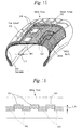
- Figure 1 is a schematic view showing a mounting state of a tire distortion detector into a vehicle according to Embodiment 1 of the present invention.
- reference numerals 101 and 102 denote metal foils (conductor piece)
- reference numeral 200 denotes a monitoring device
- reference numeral 300 denotes a tire
- reference numeral 400 denotes a tire house.
- the metal foils 101 and 102 are made of a metal such as an aluminum foil, which reflects an electromagnetic wave and is shaped like a rectangle with a predetermined width and a predetermined length.
- the plurality of metal foils 101 are arranged in lines at regular intervals along the circumferential direction, which has the axis of rotation of the tire 300 at the center, in a layer between a cap tread 301 and an under tread 302 so that the surfaces of the metal foils 101 are almost in parallel with the surface of the cap tread 301 and the long sides of the metal foils 101 match the circumferential direction which has the axis of rotation of the tire 300 at the center. Further, a distance between the adjacent metal foils 101 (length L12 of a gap) is set equal to a length L11 of the metal foil 101.
- the plurality of metal foils 102 are arranged in lines at regular intervals L22 along the circumferential direction, which has the axis of rotation of the tire 300 at the center, between a carcass 304 and a belt 303B so that the surfaces of the metal foils 102 are almost in parallel with the surface of the cap tread 301 and the long sides of the metal foils 102 match the circumferential direction which has the axis of rotation of the tire 300 at the center.
- a length L21 of the long side of the metal foil 102 is set so that the both ends in the longitudinal direction of the metal foil 102 each overlap the ends of the different metal foils 101 by a length L3.
- the metal foils 101 and 102 are arranged so that the center in the width direction of a series of conductors composed of the plurality of metal foils 101 substantially overlaps the center in the width direction of a series of conductors composed of the plurality of metal foils 102.
- the monitoring device 200 is provided in the tire house 400 of the vehicle so as to correspond with the top of the tire 300.
- the tire distortion detector of the present embodiment is constituted of the tire 300, which has the metal foils 101 and 102 embedded therein, and the monitoring device 200.
- the monitoring device 200 is constituted of a radiation unit 210, a receiving unit 220, a control section 230, an arithmetic section 240, and a distortion detecting section 250.
- the radiation unit 210 is constituted of an antenna 211, which radiates an electromagnetic wave at a predetermined frequency of 2.45 GHz, and an oscillation section 212. In response to an instruction from the control section 230, an electromagnetic wave at the above frequency is radiated like a pulse from the antenna 211.
- the oscillation section 212 is constituted of an oscillator circuit 213 and a power amplifier circuit 214.
- the oscillator circuit 213 is constituted of a known PLL circuit and so on and outputs a carrier wave at a frequency of 2.45 GHz in response to an instruction from the control section 230.
- the power amplifier 214 amplifies a carrier wave having been outputted from the oscillator circuit 131 and feeds the carrier wave as a pulse to the antenna 211.
- a pulsed electromagnetic wave at 2.45 GHz is radiated from the antenna 211.
- high-frequency power outputted from the power amplifier circuit 214 is set at a value enabling the metal foils 101 and 102 to reflect the pulsed electromagnetic wave, which has been radiated from the antenna 211 for radiating an electromagnetic wave in the monitoring device 200, as shown in Figure 1 and enabling the antenna 221, which will be described later, to receive the reflected pulsed electromagnetic wave.
- the receiving unit 220 is constituted of an antenna 221, which receives an electromagnetic wave at a frequency of 2.45 GHz, and a detecting section 222. In response to an instruction from the control section 230, the receiving unit 220 converts the high-frequency energy of an electromagnetic wave, received by the antenna 221 in a predetermined frequency band width including 2.45 GHz into direct-current voltage and outputs the voltage as a detection voltage Vout.
- the detecting section 222 is constituted of a tuned circuit 223 and a detector circuit 224.
- the tuned circuit 223 is tuned to an electromagnetic wave in a frequency band of ⁇ f1 having its center at 2.45 GHz, and the turned circuit 223 converts high-frequency energy into electric energy and outputs the electric energy.
- the detector circuit 224 converts the electric energy having been outputted from the tuned circuit 223 into direct-current voltage and outputs the voltage as the detection voltage Vout.
- the control section 230 makes initial settings when receiving an initial setting instruction from a host device (not shown) and the control section 230 detects a distortion when receiving an instruction to detect distortion from the host device.
- the initial settings are made when the tire 300 rotates with no distortion during the running of the vehicle.
- the control section 230 notifies the distortion detecting section 250 of the initial settings and then drives the oscillation section 212 to radiate the pulsed electromagnetic wave with a pulse width of time t1 at predetermined time intervals, and the control section 230 notifies the arithmetic section 240 of the timing of radiating the pulsed electromagnetic wave.
- the time intervals for radiating the pulsed electromagnetic wave are set so as to obtain one or more reflected waves from each of the metal foils 101 and 102. It is needless to say that a distortion can be accurately detected by reducing the time intervals for radiating the pulsed electromagnetic wave.
- the arithmetic section 240 measures time T from when the notification about the timing of radiation is received to when the detection voltage Vout exceeds a predetermined threshold value, that is until the reception of the pulsed electromagnetic wave having been reflected from the metal foils 101 and 102 and so on, and the arithmetic section 240 outputs the value to the distortion detecting section 250.
- the distortion detecting section 250 stores measurement time periods, which are outputted from the arithmetic section 240, sequentially in time sequence and stores a round-trip time T1 of a pulsed electromagnetic wave reflected from the metal foil 101 and a round-trip time T2 of a pulsed electromagnetic wave reflected from the metal foil 102, based on the stored values at the completion of the initial settings. Further, the distortion detecting section 250 calculates an average value T avg of measurement times T in initial setting time and stores the average value T avg. Furthermore, the distortion detecting section 250 outputs the round-trip times T1 and T2 and the average value T avg to the host device.
- the settings when the settings may be changed by the speed of the vehicle, i.e., the number of revolutions of the tire 300, it is preferable to make the settings at a plurality of speeds and determine round-trip times T1 and T2 and an average value T avg at each of the speeds.
- the control section 230 notifies the distortion detecting section 250 of distortion detection and then drives the oscillation section 212 to radiate a pulsed electromagnetic wave with a pulse width of time t1. Moreover, the control section 230 notifies the arithmetic section 250 of the timing of radiating the pulsed electromagnetic wave.
- the arithmetic section 240 measures time T from when the notification about the timing of radiation is received to when the detection voltage Vout exceeds the predetermined threshold value, that is until the reception of the pulsed electromagnetic wave having been reflected from the metal foils 101 and 102 and so on, and the arithmetic section 240 outputs the value to the distortion detecting section 250.
- the difference T dif and the measurement time T may be outputted to the host device at other predetermined time intervals and may not be outputted every time a measurement is performed.
- This setting is preferably made as necessary according to the diameter of the tire 300, the length L11 and L21 and the intervals L12 and L22 of the metal foils 101 and 102, the processing speed of the arithmetic section 240, or the requests from the host device.
- a pulsed electromagnetic wave P1 radiated from the monitoring device 200 is reflected on the metal foil 101 or the metal foil 102 and is received as a reflected wave P2 by the monitoring device 200.
- the round-trip time T of the pulsed electromagnetic wave that is measured by the monitoring device 200 repeatedly changes between the time T1 and the time T2 as shown in Figure 8. Further, time T L1 keeping the measurement time T1 and time T L2 keeping the measurement time T2 are maintained almost constant according to the length L11 of the metal foil 101, the interval L12 thereof, and the number of revolutions of the tire 300.
- time T L1A keeping the measurement time T1 and time T L2A keeping the measurement time T2 are smaller than the time T L1 and the time T L2 during which no distortion occurs.
- time T L1B keeping the measurement time T1 and time T L2B keeping the measurement time T2 are larger than the time T L1 and the time T L2 during which no distortion occurs.
- the pulsed electromagnetic wave P1 radiated from the monitoring device 200 is caused to be incident into the gap 103, the pulsed electromagnetic wave P1 is reflected by an electromagnetic reflector, for example, a rim 305 positioned closer to the axis of rotation of the tire than the metal foil 102, and the reflected wave P2 is received by a monitor unit 200.
- an electromagnetic reflector for example, a rim 305 positioned closer to the axis of rotation of the tire than the metal foil 102
- the round-trip time T of the pulsed electromagnetic wave is equal to time T3 which is larger than the round-trip time T2 of the reflection from the metal foil 102.
- the tire distortion detector is applicable to a stability controller 500 shown in Figure 13.
- a conventional and typical stability controller captures detection results outputted from sensors 510 and 520, which detect the number of revolutions of the tire 300 mounted in the vehicle, to perform stability control.
- the stability controller 500 in which the tire 300 and the monitoring device 200 are provided and detection results outputted from the monitoring device 200 are captured to perform stability control, to the conventional configuration, it is possible to perform control with higher accuracy.
- an instruction from the monitoring device 200 to the control section 230 is outputted from the stability controller 500.
- Embodiment 2 of the present invention has two monitoring devices 200A and 200B at the front and back of the top of a tire house 400.
- an electromagnetic wave may be radiated and received in a time-sharing manner by the monitoring devices 200A and 200B.
- a distortion can be detected on two points of a tire 300.
- a monitoring device 200 may be provided on three or more points of the tire house 400 so as to detect a distortion on three points of the tire 300.
- Embodiment 3 of the present invention as shown in Figures 15 and 16, a tire 300A is provided instead of the tire 300 of Embodiment 1.
- Embodiment 3 is different from Embodiment 1 only in the tire 300A.
- a series of conductors composed of a plurality of metal foils 101 and a series of conductors composed of a plurality of metal foils 102 are displaced in opposite directions along the width of the tire 300A.
- the widths of the metal foil 101 and the metal foil 102 are set as Embodiment 1 and only a width L5 of an overlap of the metal foil 101 and the metal foil 102 is set smaller than that of Embodiment 1. Therefore, it is possible to increase the accuracy of detecting a distortion in the width direction of the tire 300A.
- a pulsed electromagnetic wave has a frequency of 2.45 GHz in the above-described embodiments, the frequency is not particularly limited. As described above, a frequency at 1 GHz or higher can remarkably reduce the influence of a reinforcing metal in the tire that reflects and interrupts an electromagnetic wave, thereby detecting a distortion of the tire with high accuracy. Moreover, it is preferable to properly set a frequency of a pulsed electromagnetic wave in consideration of the influence of the reinforcing metal and so on in designing.
- a workload for manufacturing a tire can be reduced as compared with the conventional art, applicability is widened to a control system such as a stability control system, a deterioration and a damage in a sensor unit can be reduced that are caused by heat generated on the tire during the running of the vehicle, and a distortion of the tire can be detected with high accuracy.
- a control system such as a stability control system
- a deterioration and a damage in a sensor unit can be reduced that are caused by heat generated on the tire during the running of the vehicle, and a distortion of the tire can be detected with high accuracy.
Abstract
The present invention provides a tire distortion detecting method,
a distortion detector, and a tire which can reduce the occurrence of
a deterioration and can be used for a control system such as a stability
control system. That is, series of conductors composed of a plurality
of conductor pieces 101 and 102 are provided in two different layers.
The conductor pieces 101 and 102 are embedded in lines at predetermined
intervals in the circumferential direction of a tire 300. A pulsed
electromagnetic wave is radiated to the surfaces of metal foils 101
and 102 in the layers from a monitoring device 200 provided in a tire
house 400 of a vehicle. The monitoring device 200 receives a pulsed
electromagnetic wave reflected from the metal foils 101 and 102 in the
layers or a member other than the metal foils. Time from the radiation
of a pulsed electromagnetic wave to the reception of a reflected pulsed
magnetic wave is measured repeatedly, time at which no distortion
occurs on the tire 300 is stored as a reference value, and the measured
time and the stored reference value are compared with each other to
detect a distortion of the tire 300.
Description
- The present invention relates to a tire distortion detecting method, a distortion detector, and a tire thereof that detects a distortion of the tire during the running of a vehicle.
- Conventionally cautions for the safe driving of a vehicle include a proper setting of an air pressure in a tire of the vehicle and attention to the wear of the tire. For example, a reduced air pressure in a tire increases the occurrence of flat tires and causes a burst at high speed, resulting in a serious accident. Therefore, drivers have to check tires on a daily basis.
- However, even if tires are checked and preferred conditions are maintained for the tires, when a friction between a road surface and the tires decreases, for example, when a road surface is wet on a rainy day, skids occur under braking and move the vehicle in an unexpected direction, resulting in some accidents.
- In order to prevent accidents caused by skids and a fast start, Anti-Lock Brake System (hereinafter referred to as ABS) and a traction control system are developed, and a stability control system having a YAW sensor is also developed in addition to these systems.
- For example, ABS is a system of detecting a rotating state of each tire and controlling a braking force based on detection results so as to prevent the tires from locking.
- The number of revolutions, an air pressure, a distortion, and so forth of each tire are detected as a rotating state of tires and detection results can be used for control.
- For example, a detector for automatically detecting an air pressure of a tire is known. Such a detector uses a so-called "indirect" method of detecting an air pressure of a tire. In this method, data is inputted from an ABS speed sensor to estimate an air pressure of a tire.
- As a method of detecting an air pressure of a tire that is used for the detector, the following methods are known: (a) a method of calculating a change (distortion) in the rolling radius of a tire by an angular speed of rotation of a wheel, the change being caused by a reduced air pressure, and (b) a method of performing FFT (Fast Fourier Transform) on an input signal and performing calculations using a change in the natural frequency of a tire.
- On the other hand, as examples of a sensor and a tire that are used for the ABS, the traction control system, and the stability control system, U.S.P. No. 5,895,854 (hereinafter referred to as conventional example 1) and U.S.P. No. 6,308,758 (hereinafter referred to as conventional example 2) are known.
- In conventional example 1, magnetic bar codes are provided which are arranged in lines in the circumferential direction of the side wall of a tire with adjacent parts alternately changed in polarity, and the bar codes are read by a sensor fixed on a chassis and a axis arm. Thus, the rotating speed of the tire can be detected. Further, the magnetic bar codes are provided in two or more lines in the radius direction of the tire, thereby calculating a force and deformation in the radius direction of the tire based on a phase difference between the detection results of the inner and outer magnetic bar codes.
- In contrast to conventional example 1 having difficulty in forming magnetic bands at small intervals, conventional example 2 reduces the difficulty and discloses a tire improved in the resolution of magnetic bar codes arranged in lines in the circumferential direction of the side wall of the tire with adjacent parts alternately changed in polarity.
- However, in conventional examples 1 and 2, since the magnetic bands are formed on the side wall when the tire is manufactured, it is quite troublesome to set the magnetic force of the magnetic band at the optimum value. That is, when the magnetic force of the magnetic band is much higher than the optimum value, a magnetic substance such as iron sand and an iron piece on a road surface may be adsorbed. Further, when the magnetic force of the magnetic band is lower than the optimum value, the detection of the sensor becomes difficult.
- Moreover, the magnetic bands may gradually decrease in magnetization due to heat generated on the tire during the running of a vehicle and the detection of the sensor may become more difficult as running time increases.
- In view of the above problems, an object of the present invention is to provide a tire distortion detecting method, a distortion detector, and a tire that can reduce the occurrence of a deterioration and can be used for a control system such as a stability control system.
- A tire distortion detecting method of the present invention uses a tire, in which a plurality of conductor pieces embedded in lines at predetermined intervals in the circumferential direction of the tire are embedded in two or more different layers, and a monitoring device which has a scanner unit provided in a tire house of a vehicle. When a distortion of a rotating tire is detected by using the tire and the monitoring device, a pulsed electromagnetic wave is radiated to the surface of the conductor piece along the lines of the conductor pieces in each of the layers. Further, the scanner unit receives the pulsed electromagnetic wave reflected from the conductor piece in each of the layers and a member other than the conductor pieces. The monitoring device repeatedly measures time from when the scanner unit radiates the pulsed electromagnetic wave to when the scanner unit receives the reflected pulsed electromagnetic wave. The monitoring device stores, as a reference value, time at which no distortion occurs on the tire and compares an actually measured time with the stored reference value to detect a distortion of the tire.
- According to the tire distortion detecting method of the present invention, the pulsed electromagnetic wave radiated from the scanner unit is reflected by the conductor piece or another member having a characteristic of reflecting an electromagnetic wave, and the reflected pulsed electromagnetic wave is received by the scanner unit.
- Time from when the scanner unit radiates a pulsed electromagnetic wave to when the scanner unit receives the reflected wave, i.e., the round-trip time of the pulsed electromagnetic wave changes according to a distance between the scanner unit and a reflector for reflecting the pulsed electromagnetic wave. Further, when a distortion of the tire changes, a difference in the round-trip time of a pulsed electromagnetic wave also changes that corresponds to each of the conductor pieces embedded in the different layers. Moreover, when a distortion of the tire changes, the conductor pieces are displaced according to the distortion and a pulsed electromagnetic wave radiated from the scanner unit is reflected to the scanner unit by a member other than the conductor pieces. Therefore, it is possible to detect a distortion of the tire by the round-trip time of a pulsed electromagnetic wave or a difference in the round-trip time of the different layers.
- Besides, according to the tire distortion detecting method of the present invention, the monitoring device radiates one or more pulsed electromagnetic waves in an interval of a smaller distance or length, out of a distance between the conductor pieces adjacent to each other in the circumferential direction of the tire or the length of the conductor piece arranged in the circumferential direction of the tire, so that time measurement is conducted on all the conductor pieces and between the adjacent conductor pieces. The tire distortion detecting method of the present invention can obtain resolutions more than the number of the conductor pieces arranged in lines along the circumferential direction of the tire, thereby detecting a distortion with high accuracy.
- Additionally, according to the tire distortion detecting method of the present invention, the monitoring device uses a frequency of 1 GHz or higher to radiate a pulsed electromagnetic wave. Thus, it is possible to reduce the influence of reflection made by a reinforcing metal in the tire, the reinforcing metal having a gap larger than the wavelength of the frequency.
- Besides, a tire distortion detector is constituted of a tire, in which a plurality of conductor pieces embedded in lines at predetermined intervals in the circumferential direction of the tire are embedded in two or more different layers, and a monitoring device which has a scanner unit provided in a tire house of a vehicle.
- The monitoring device comprises means for radiating a pulsed electromagnetic wave from the scanner unit to a surface of the conductor piece along the line of the conductor pieces in each of the layers of the tire, means which is provided in the scanner unit and receives the pulsed electromagnetic wave reflected by the conductor piece in each of the layers of the tire and a member other than the conductor piece, means for measuring time from the radiation of the pulsed electromagnetic wave to the reception of the reflected pulsed electromagnetic wave, means for alternately repeating the radiation of the pulsed electromagnetic wave and the reception of the reflected pulsed electromagnetic wave, means for storing, as a reference value, time at which no distortion occurs on the tire, and means for comparing the measured time and the stored reference value to detect a distortion of the tire.
- According to the tire distortion detector of the present invention, the pulsed electromagnetic wave radiated from the scanner unit is reflected by the conductor piece or another member having a characteristic of reflecting an electromagnetic wave, and the reflected pulsed electromagnetic wave is received by the scanner unit.
- Time from when the scanner unit radiates a pulsed electromagnetic wave to when the scanner unit receives the reflected wave, i.e., the round-trip time of the pulsed electromagnetic wave changes according to a distance between the scanner unit and a reflector for reflecting the pulsed electromagnetic wave.
- Further, when a distortion of the tire changes, a difference in the round-trip time of a pulsed electromagnetic wave also changes that corresponds to each of the conductor pieces embedded in the different layers. Moreover, when a distortion of the tire changes, the conductor pieces are displaced according to the distortion and a pulsed electromagnetic wave radiated from the scanner unit is reflected to the scanner unit by a member other than the conductor pieces.
- The monitoring device repeatedly measures the round-trip time of a pulsed electromagnetic wave and stores, as a reference value, time at which no distortion occurs on the tire. Further, the monitoring device compares time measured in the running of the vehicle with the stored reference value to detect a distortion of the tire. Therefore, it is possible to detect a distortion of the tire by the round-trip time of a pulsed electromagnetic wave or a difference in the round-trip time of a pulsed electromagnetic wave in the different layers of the tire.
- Moreover, according to the tire distortion detector of the present invention, when a distortion is made detectable mainly on the tread of the tire, the conductor pieces are embedded in the tire so that the surfaces of the conductor pieces are almost in parallel with the surface of the tire tread.
- Besides, according to the tire distortion detector of the present invention, when a distortion is made detectable mainly on the side wall of the tire, the conductor pieces are embedded in the tire so that the surfaces of the conductor pieces are almost in parallel with the surface of the side wall of the tire.
- Additionally, according to the tire distortion detector of the present invention, the pulsed electromagnetic wave is set at a frequency of 1 GHz or higher in order to reduce the influence of reflection made by the reinforcing metal in the tire, the reinforcing metal having a gap larger than the wavelength of the frequency.
- Moreover, according to the tire distortion detector of the present invention, at least in the outermost line of the conductor pieces relative to the axis of rotation of the tire at the center, the conductor pieces are arranged at regular intervals in the circumferential direction of the tire to set the length of the conductor piece in the circumferential direction of the tire equal to the length of a gap between the adjacent conductor pieces, so that measurement time changes at regular intervals when the tire having no distortion rotates at a fixed number of revolutions.
- Besides, according to the tire distortion detector of the present invention, the conductor pieces are arranged so that in a second series of conductors provided inside a first series of conductors, the ends of the conductor piece in the circumferential direction of the tire overlap, by a predetermined length, the ends of the conductor piece in the circumferential direction of the tire in the first series of conductors which is outermost relative to the axis of rotation of the tire at the center.
- According to the tire distortion detector of the present invention, when a distortion of the tire is larger than a predetermined amount, an overlap disappears between the conductor piece of the first series of conductors and the conductor piece of the second series of conductors and a gap appears between the series of conductors. The occurrence of the gap largely changes the round-trip time of a pulsed electromagnetic wave and thus it is possible to detect that a distortion of the tire has become larger than the predetermined amount.
- Further, according to the present invention, as a tire used for the tire distortion detector, a tire is configured so that series of conductors are embedded in two or more different layers with a part having no overlapping surface, the series of conductors being composed of a plurality of conductor pieces embedded in lines at predetermined intervals in the circumferential direction of the tire.
- Moreover, according to the tire of the present invention, when a distortion is made detectable mainly on the tread of the tire, the conductor pieces are embedded in the tire so that the surfaces of the conductor pieces are almost in parallel with the surface of the tire tread.
- Besides, according to the tire of the present invention, when a distortion is made detectable mainly on the side wall of the tire, the conductor pieces are embedded in the tire so that the surfaces of the conductor pieces are almost in parallel with the surface of the side wall of the tire.
- Additionally, according to the tire of the present invention, at least in the outermost line of the conductor pieces relative to the axis of rotation of the tire at the center, the conductor pieces are arranged at regular intervals in the circumferential direction of the tire to set the length of the conductor piece in the circumferential direction of the tire equal to the length of a gap between the adjacent conductor pieces.
- Further, according to the tire of the present invention, the conductor pieces are arranged so that in a second series of conductors provided inside a first series of conductors, the ends of the conductor piece in the circumferential direction of the tire overlap, by a predetermined length, the ends of the conductor piece in the circumferential direction of the tire in the first series of conductors which is outermost relative to the axis of rotation of the tire at the center.
- According to the tire of the present invention, the conductor pieces are arranged at regular intervals in the same layer.
- According to the tire of the present invention, the conductor pieces of the layers are arranged so that the conductor pieces in the two different layers are alternately arranged in the circumferential direction of the tire.
- According to the tire of the present invention, the conductor pieces of the layers in the tire are arranged so that the conductor pieces partly overlap each other in the circumferential direction of the tire.
- According to the tire of the present invention, the conductor pieces of the layers in the tire are displaced from each other in the width direction of the tire.
-
- Figure 1 is a schematic diagram showing a state of mounting a
tire distortion detector into a vehicle according to
Embodiment 1 of the present invention; - Figure 2 is a top view showing the tire according to
Embodiment 1 of the present invention; - Figure 3 is cutaway view showing a state of embedding metal foils
in the tire according to
Embodiment 1 of the present invention; - Figure 4 is a diagram for explaining an overlapping state of the
metal foils of different layers according to
Embodiment 1 of the present invention; - Figure 5 is a structural diagram showing a specific example of
an electrical circuit of a monitoring device according to
Embodiment 1 of the present invention. - Figure 6 is a diagram for explaining a method of detecting a
distortion of the tire according to
Embodiment 1 of the present invention; - Figure 7 is a diagram for explaining the method of detecting a
distortion of the tire according to
Embodiment 1 of the present invention; - Figure 8 is a timing chart for explaining the method of detecting
a distortion of the tire according to
Embodiment 1 of the present invention; - Figure 9 is a timing chart for explaining the method of detecting
a distortion of the tire according to
Embodiment 1 of the present invention; - Figure 10 is a timing chart for explaining the method of detecting
a distortion of the tire according to
Embodiment 1 of the present invention; - Figure 11 is a diagram for explaining the method of detecting
a distortion of the tire according to
Embodiment 1 of the present invention; - Figure 12 is a timing chart for explaining the method of detecting
a distortion of the tire according to
Embodiment 1 of the present invention; - Figure 13 is a diagram for explaining a use example of the tire
distortion detector according to
Embodiment 1 of the present invention; - Figure 14 is a schematic diagram showing a state of mounting a tire distortion detector into a vehicle according to Embodiment 2 of the present invention;
- Figure 15 is cutaway view showing a state of embedding metal foils in the tire according to Embodiment 3 of the present invention; and
- Figure 16 is a top view for explaining a state of embedding the metal foils in the tire according to Embodiment 3 of the present invention.
-
- The following will describe embodiments of the present invention in accordance with the accompanying drawings.
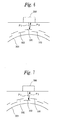
- Figure 1 is a schematic view showing a mounting state of a tire distortion detector into a vehicle according to
Embodiment 1 of the present invention. In Figure 1,reference numerals reference numeral 200 denotes a monitoring device,reference numeral 300 denotes a tire, andreference numeral 400 denotes a tire house. - The metal foils 101 and 102 are made of a metal such as an aluminum foil, which reflects an electromagnetic wave and is shaped like a rectangle with a predetermined width and a predetermined length.
- As shown in Figures 2 to 4, the plurality of metal foils 101 are arranged in lines at regular intervals along the circumferential direction, which has the axis of rotation of the
tire 300 at the center, in a layer between acap tread 301 and an undertread 302 so that the surfaces of the metal foils 101 are almost in parallel with the surface of thecap tread 301 and the long sides of the metal foils 101 match the circumferential direction which has the axis of rotation of thetire 300 at the center. Further, a distance between the adjacent metal foils 101 (length L12 of a gap) is set equal to a length L11 of themetal foil 101. - Moreover, the plurality of metal foils 102 are arranged in lines at regular intervals L22 along the circumferential direction, which has the axis of rotation of the
tire 300 at the center, between acarcass 304 and abelt 303B so that the surfaces of the metal foils 102 are almost in parallel with the surface of thecap tread 301 and the long sides of the metal foils 102 match the circumferential direction which has the axis of rotation of thetire 300 at the center. Additionally, as shown in Figure 4, a length L21 of the long side of themetal foil 102 is set so that the both ends in the longitudinal direction of themetal foil 102 each overlap the ends of the different metal foils 101 by a length L3. - Further, the metal foils 101 and 102 are arranged so that the center in the width direction of a series of conductors composed of the plurality of metal foils 101 substantially overlaps the center in the width direction of a series of conductors composed of the plurality of metal foils 102.
- The
monitoring device 200 is provided in thetire house 400 of the vehicle so as to correspond with the top of thetire 300. The tire distortion detector of the present embodiment is constituted of thetire 300, which has the metal foils 101 and 102 embedded therein, and themonitoring device 200. - As shown in Figure 5, the
monitoring device 200 is constituted of aradiation unit 210, a receivingunit 220, acontrol section 230, anarithmetic section 240, and adistortion detecting section 250. - The
radiation unit 210 is constituted of anantenna 211, which radiates an electromagnetic wave at a predetermined frequency of 2.45 GHz, and anoscillation section 212. In response to an instruction from thecontrol section 230, an electromagnetic wave at the above frequency is radiated like a pulse from theantenna 211. - The
oscillation section 212 is constituted of anoscillator circuit 213 and apower amplifier circuit 214. Theoscillator circuit 213 is constituted of a known PLL circuit and so on and outputs a carrier wave at a frequency of 2.45 GHz in response to an instruction from thecontrol section 230. - The
power amplifier 214 amplifies a carrier wave having been outputted from the oscillator circuit 131 and feeds the carrier wave as a pulse to theantenna 211. Thus, a pulsed electromagnetic wave at 2.45 GHz is radiated from theantenna 211. Additionally, high-frequency power outputted from thepower amplifier circuit 214 is set at a value enabling the metal foils 101 and 102 to reflect the pulsed electromagnetic wave, which has been radiated from theantenna 211 for radiating an electromagnetic wave in themonitoring device 200, as shown in Figure 1 and enabling theantenna 221, which will be described later, to receive the reflected pulsed electromagnetic wave. - The receiving
unit 220 is constituted of anantenna 221, which receives an electromagnetic wave at a frequency of 2.45 GHz, and a detectingsection 222. In response to an instruction from thecontrol section 230, the receivingunit 220 converts the high-frequency energy of an electromagnetic wave, received by theantenna 221 in a predetermined frequency band width including 2.45 GHz into direct-current voltage and outputs the voltage as a detection voltage Vout. - The detecting
section 222 is constituted of atuned circuit 223 and adetector circuit 224. - The
tuned circuit 223 is tuned to an electromagnetic wave in a frequency band of ±Δf1 having its center at 2.45 GHz, and the turnedcircuit 223 converts high-frequency energy into electric energy and outputs the electric energy. - The
detector circuit 224 converts the electric energy having been outputted from the tunedcircuit 223 into direct-current voltage and outputs the voltage as the detection voltage Vout. - The
control section 230 makes initial settings when receiving an initial setting instruction from a host device (not shown) and thecontrol section 230 detects a distortion when receiving an instruction to detect distortion from the host device. - The initial settings are made when the
tire 300 rotates with no distortion during the running of the vehicle. - In the initial settings, the
control section 230 notifies thedistortion detecting section 250 of the initial settings and then drives theoscillation section 212 to radiate the pulsed electromagnetic wave with a pulse width of time t1 at predetermined time intervals, and thecontrol section 230 notifies thearithmetic section 240 of the timing of radiating the pulsed electromagnetic wave. Besides, it is preferable that the time intervals for radiating the pulsed electromagnetic wave are set so as to obtain one or more reflected waves from each of the metal foils 101 and 102. It is needless to say that a distortion can be accurately detected by reducing the time intervals for radiating the pulsed electromagnetic wave. - The
arithmetic section 240 measures time T from when the notification about the timing of radiation is received to when the detection voltage Vout exceeds a predetermined threshold value, that is until the reception of the pulsed electromagnetic wave having been reflected from the metal foils 101 and 102 and so on, and thearithmetic section 240 outputs the value to thedistortion detecting section 250. - In the initial settings, the
distortion detecting section 250 stores measurement time periods, which are outputted from thearithmetic section 240, sequentially in time sequence and stores a round-trip time T1 of a pulsed electromagnetic wave reflected from themetal foil 101 and a round-trip time T2 of a pulsed electromagnetic wave reflected from themetal foil 102, based on the stored values at the completion of the initial settings. Further, thedistortion detecting section 250 calculates an average value T avg of measurement times T in initial setting time and stores the average value T avg. Furthermore, thedistortion detecting section 250 outputs the round-trip times T1 and T2 and the average value T avg to the host device. - In the initial settings, when the settings may be changed by the speed of the vehicle, i.e., the number of revolutions of the
tire 300, it is preferable to make the settings at a plurality of speeds and determine round-trip times T1 and T2 and an average value T avg at each of the speeds. - Further, in the distortion detection, the
control section 230 notifies thedistortion detecting section 250 of distortion detection and then drives theoscillation section 212 to radiate a pulsed electromagnetic wave with a pulse width of time t1. Moreover, thecontrol section 230 notifies thearithmetic section 250 of the timing of radiating the pulsed electromagnetic wave. - The
arithmetic section 240 measures time T from when the notification about the timing of radiation is received to when the detection voltage Vout exceeds the predetermined threshold value, that is until the reception of the pulsed electromagnetic wave having been reflected from the metal foils 101 and 102 and so on, and thearithmetic section 240 outputs the value to thedistortion detecting section 250. - The
distortion detecting section 250 calculates a difference T dif (=T-T avg) between the measurement time T, which is outputted from thearithmetic section 240, and the stored average value T avg, and thedistortion detecting section 250 outputs the difference T dif and the measurement time T sequentially in time sequence to the host device. - The difference T dif and the measurement time T may be outputted to the host device at other predetermined time intervals and may not be outputted every time a measurement is performed. This setting is preferably made as necessary according to the diameter of the
tire 300, the length L11 and L21 and the intervals L12 and L22 of the metal foils 101 and 102, the processing speed of thearithmetic section 240, or the requests from the host device. - The following will describe a tire distortion detecting method using the detector configured thus.
- When no distortion occurs on the
tire 300, as shown in Figures 6 and 7, a pulsed electromagnetic wave P1 radiated from themonitoring device 200 is reflected on themetal foil 101 or themetal foil 102 and is received as a reflected wave P2 by themonitoring device 200. - At this point, the round-trip time T of the pulsed electromagnetic wave that is measured by the
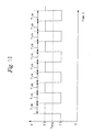
monitoring device 200 repeatedly changes between the time T1 and the time T2 as shown in Figure 8. Further, time TL1 keeping the measurement time T1 and time TL2 keeping the measurement time T2 are maintained almost constant according to the length L11 of themetal foil 101, the interval L12 thereof, and the number of revolutions of thetire 300. - On the other hand, when the
tire 300 has the same number of revolutions and a pressure is applied from the front and back to the top of thetire 300 so as to compress the top of thetire 300, the length L11 and the interval L12 of themetal foil 101 are reduced. Hence, as shown in Figure 9, time TL1A keeping the measurement time T1 and time TL2A keeping the measurement time T2 are smaller than the time TL1 and the time TL2 during which no distortion occurs. - Moreover, when the
tire 300 has the same number of revolutions and a pressure is applied from the top of thetire 300 to the front and back so as to expand the top of thetire 300, the length L11 and the interval L12 of themetal foil 101 are increased. Hence, as shown in Figure 10, time TL1B keeping the measurement time T1 and time TL2B keeping the measurement time T2 are larger than the time TL1 and the time TL2 during which no distortion occurs. - Furthermore, when the pressure from the top of the
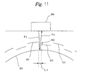
tire 300 to the front and back increases, a part having themetal foil 101 and themetal foil 102 overlapping in the circumferential direction of the tire (an overlap with the length L3) disappears and agap 103 with a length L4 appears between themetal foil 101 and themetal foil 102. When the pulsed electromagnetic wave P1 radiated from themonitoring device 200 is caused to be incident into thegap 103, the pulsed electromagnetic wave P1 is reflected by an electromagnetic reflector, for example, arim 305 positioned closer to the axis of rotation of the tire than themetal foil 102, and the reflected wave P2 is received by amonitor unit 200. - At this point, as shown in Figure 12, the round-trip time T of the pulsed electromagnetic wave is equal to time T3 which is larger than the round-trip time T2 of the reflection from the
metal foil 102. - Therefore, a distortion of the
tire 300 can be detected by using the difference T dif (=T-T avg) outputted from the distortion detecting section 205. - For example, the tire distortion detector is applicable to a
stability controller 500 shown in Figure 13. A conventional and typical stability controller captures detection results outputted fromsensors tire 300 mounted in the vehicle, to perform stability control. By adding thestability controller 500, in which thetire 300 and themonitoring device 200 are provided and detection results outputted from themonitoring device 200 are captured to perform stability control, to the conventional configuration, it is possible to perform control with higher accuracy. In this case, an instruction from themonitoring device 200 to thecontrol section 230 is outputted from thestability controller 500. - Further, as shown in Figure 14, Embodiment 2 of the present invention has two
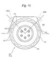
monitoring devices tire house 400. In this case, an electromagnetic wave may be radiated and received in a time-sharing manner by themonitoring devices tire 300. Additionally amonitoring device 200 may be provided on three or more points of thetire house 400 so as to detect a distortion on three points of thetire 300. - Moreover, according to Embodiment 3 of the present invention, as shown in Figures 15 and 16, a
tire 300A is provided instead of thetire 300 ofEmbodiment 1. Embodiment 3 is different fromEmbodiment 1 only in thetire 300A. - In the
tire 300A, a series of conductors composed of a plurality of metal foils 101 and a series of conductors composed of a plurality of metal foils 102 are displaced in opposite directions along the width of thetire 300A. Besides, the widths of themetal foil 101 and themetal foil 102 are set asEmbodiment 1 and only a width L5 of an overlap of themetal foil 101 and themetal foil 102 is set smaller than that ofEmbodiment 1. Therefore, it is possible to increase the accuracy of detecting a distortion in the width direction of thetire 300A. - The above-described embodiments are specific examples of the present invention and thus the present invention is not limited to these embodiments. For example, it is needless to say that the same effect can be obtained by a configuration having the metal foils 101 and 102 on the side wall of the tire.
- Further, although a pulsed electromagnetic wave has a frequency of 2.45 GHz in the above-described embodiments, the frequency is not particularly limited. As described above, a frequency at 1 GHz or higher can remarkably reduce the influence of a reinforcing metal in the tire that reflects and interrupts an electromagnetic wave, thereby detecting a distortion of the tire with high accuracy. Moreover, it is preferable to properly set a frequency of a pulsed electromagnetic wave in consideration of the influence of the reinforcing metal and so on in designing.
- Moreover, it is needless to say that these embodiments are applicable to sensors for a traction controller or a device which performs active control on a suspension, a stabilizer in the suspension, and so on.
- As described above, according to the present invention, a workload for manufacturing a tire can be reduced as compared with the conventional art, applicability is widened to a control system such as a stability control system, a deterioration and a damage in a sensor unit can be reduced that are caused by heat generated on the tire during the running of the vehicle, and a distortion of the tire can be detected with high accuracy.
Claims (18)
- A tire distortion detecting method for detecting a distortion of a rotating tire by using a tire, in which a plurality of conductor pieces embedded in lines at predetermined intervals in a circumferential direction of the tire are embedded in two or more different layers, and a monitoring device which has a scanner unit provided in a tire house of a vehicle,
characterized in that the monitoring device radiates a pulsed electromagnetic wave from the scanner unit to a surface of the conductor piece along the line of the conductor pieces in each of the layers,
causes the scanner unit to receive the pulsed electromagnetic wave reflected from the conductor piece in each of the layers and a member other than the conductor pieces,
repeatedly measures time from when the pulsed electromagnetic wave is radiated to when the reflected pulsed electromagnetic wave is received,
stores, as a reference value, time at which no distortion occurs on the tire, and
compares the measured time with the stored reference value to detect a distortion of the tire. - The tire distortion detecting method according to claim 1, characterized in that the monitoring device radiates one or more pulsed electromagnetic waves in an interval of a smaller distance or length out of a distance between the conductor pieces adjacent to each other in the circumferential direction of the tire or a length of the conductor piece arranged in the circumferential direction of the tire, so that the time measurement is conducted on all the conductor pieces and between the adjacent conductor pieces.
- The tire distortion detecting method according to claim 1, characterized in that the monitoring device uses a frequency of 1 GHz or higher to radiate the pulsed electromagnetic wave.
- A tire distortion detector for detecting a distortion of a tire in running of a vehicle, the detector being constituted of:characterized in that the monitoring device comprises:a tire, in which a plurality of conductor pieces embedded in lines at predetermined intervals in a circumferential direction of the tire are embedded in two or more different layers, anda monitoring device which has a scanner unit provided in a tire house of the vehicle,means for radiating a pulsed electromagnetic wave from the scanner unit to a surface of the conductor piece along the line of the conductor pieces in each of the layers of the tire,means which is provided in the scanner unit and receives the pulsed electromagnetic wave reflected by the conductor piece in each of the layers of the tire and a member other than the conductor piece,means for measuring time from radiation of the pulsed electromagnetic wave to reception of the reflected pulsed electromagnetic wave,means for alternately repeating the radiation of the pulsed electromagnetic wave and the reception of the reflected pulsed electromagnetic wave,means for storing, as a reference value, time at which no distortion occurs on the tire, andmeans for comparing the measured time and the stored reference value to detect a distortion of the tire.
- The tire distortion detector according to claim 4, characterized in that the conductor pieces are embedded in the tire so that surfaces of the conductor pieces are almost in parallel with a surface of a tire tread.
- The tire distortion detector according to claim 4, characterized in that the conductor pieces are embedded in the tire so that the surfaces of the conductor pieces are almost in parallel with a surface of a side wall of the tire.
- The tire distortion detector according to claim 4, characterized in that the pulsed electromagnetic wave is set at a frequency of 1 GHz or higher.
- The tire distortion detector according to claim 4, characterized in that at least in an outermost line of the conductor pieces relative to an axis of rotation of the tire at the center, the conductor pieces are arranged at regular intervals in the circumferential direction of the tire to set a length of the conductor piece in the circumferential direction of the tire equal to a length of a gap between the adjacent conductor pieces.
- The tire distortion detector according to claim 4, characterized in that the conductor pieces are arranged so that in a second series of conductors provided inside a first series of conductors, ends of the conductor piece in the circumferential direction of the tire overlap, by a predetermined length, ends of the conductor piece in the circumferential direction of the tire in the first series of conductors which is outermost relative to an axis of rotation of the tire at the center.
- A tire, characterized in that series of conductors are embedded in two or more different layers with a part having no overlapping surfaces, the series of conductors being composed of a plurality of conductor pieces embedded in lines at predetermined intervals in a circumferential direction of the tire.
- The tire according to claim 10, characterized in that the conductor pieces are embedded in the tire so that the surfaces of the conductor pieces are almost in parallel with a surface of a tire tread.
- The tire according to claim 10, characterized in that the conductor pieces are embedded in the tire so that the surfaces of the conductor pieces are almost in parallel with a surface of a side wall of the tire.
- The tire according to claim 10, characterized in that at least in an outermost line of the conductor pieces relative to an axis of rotation of the tire at the center, the conductor pieces are arranged at regular intervals in the circumferential direction of the tire to set a length of the conductor piece in the circumferential direction of the tire equal to a length of a gap between the adjacent conductor pieces.
- The tire according to claim 10, characterized in that the conductor pieces are arranged so that in a second series of conductors provided inside a first series of conductors, ends of the conductor piece in the circumferential direction overlap, by a predetermined length, ends of the conductor piece in the circumferential direction of the tire in the first series of conductors which is outermost relative to an axis of rotation of the tire at the center.
- The tire according to claim 10, characterized in that the conductor pieces are arranged at regular intervals in the same layer.
- The tire according to claim 10, characterized in that the conductor pieces of the layers are arranged so that the conductor pieces in the two different layers are alternately arranged in the circumferential direction of the tire.
- The tire according to claim 16, characterized in that the conductor pieces of the layers are arranged so that the conductor pieces partly overlap each other in the circumferential direction of the tire.
- The tire according to any one of claims 10 to 17, characterized in that the conductor pieces of the layers are displaced from each other in a width direction of the tire.
Applications Claiming Priority (3)
| Application Number | Priority Date | Filing Date | Title |
|---|---|---|---|
| JP2002226050 | 2002-08-02 | ||
| JP2002226050A JP4231254B2 (en) | 2002-08-02 | 2002-08-02 | Tire distortion state detection method, distortion state detection apparatus, and tire |
| PCT/JP2003/009169 WO2004013596A1 (en) | 2002-08-02 | 2003-07-18 | Method for detecting strain state of tire, device for detecting strain state, and the tire |
Publications (2)
| Publication Number | Publication Date |
|---|---|
| EP1526367A1 true EP1526367A1 (en) | 2005-04-27 |
| EP1526367A4 EP1526367A4 (en) | 2006-11-22 |
Family
ID=31492177
Family Applications (1)
| Application Number | Title | Priority Date | Filing Date |
|---|---|---|---|
| EP03741492A Withdrawn EP1526367A4 (en) | 2002-08-02 | 2003-07-18 | Method for detecting strain state of tire, device for detecting strain state, and the tire |
Country Status (4)
| Country | Link |
|---|---|
| US (3) | US7302836B2 (en) |
| EP (1) | EP1526367A4 (en) |
| JP (1) | JP4231254B2 (en) |
| WO (1) | WO2004013596A1 (en) |
Cited By (1)
| Publication number | Priority date | Publication date | Assignee | Title |
|---|---|---|---|---|
| US7752904B2 (en) | 2005-03-04 | 2010-07-13 | Purdue Research Foundation | Structures with integral life-sensing capability |
Families Citing this family (21)
| Publication number | Priority date | Publication date | Assignee | Title |
|---|---|---|---|---|
| JP4231254B2 (en) * | 2002-08-02 | 2009-02-25 | 横浜ゴム株式会社 | Tire distortion state detection method, distortion state detection apparatus, and tire |
| FR2861869A1 (en) * | 2003-11-05 | 2005-05-06 | Michelin Soc Tech | PROCESS FOR EXTRACTING AT LEAST ONE SIZE CHARACTERIZING A PERIODIC SIGNAL, AND APPLICATION |
| US7082819B2 (en) * | 2003-12-09 | 2006-08-01 | Michelin Recherche Et Technique S.A. | Doppler radar for detecting tire abnormalities |
| JP2006170686A (en) * | 2004-12-14 | 2006-06-29 | Sumitomo Electric Ind Ltd | Tire condition sensor, tire condition sensing method, tire and antenna |
| JP4663385B2 (en) * | 2005-04-18 | 2011-04-06 | 株式会社ブリヂストン | Method for correcting irregularities on the surface of a rotating body |
| JP5075623B2 (en) * | 2005-04-26 | 2012-11-21 | 三洋電機株式会社 | Tire sensor system and body mounted with the same |
| US7284417B2 (en) * | 2005-07-28 | 2007-10-23 | Reynolds Charles W | Tire monitor |
| FR2891770B1 (en) * | 2005-10-06 | 2007-12-07 | Michelin Soc Tech | METHOD AND DEVICE FOR INFLATION PRESSURE MEASUREMENT OF A TIRE BY MEANS OF A STRAIN SENSOR |
| DE102006014058B4 (en) * | 2006-03-27 | 2008-04-17 | Mähner, Bernward | Apparatus and method for optically testing a tire |
| JP4939210B2 (en) * | 2006-12-28 | 2012-05-23 | 住友ゴム工業株式会社 | Tire longitudinal force detection method and pneumatic tire used therefor |
| US8291753B2 (en) | 2007-05-29 | 2012-10-23 | Paul E. Hawkinson Company | Tire defect tester |
| US8281827B2 (en) * | 2008-11-06 | 2012-10-09 | The Yokohama Rubber Co., Ltd. | Pneumatic tire |
| FR2992453B1 (en) * | 2012-06-22 | 2014-07-04 | Ldl Technology | DEVICE FOR COMMUNICATING A WHEEL MONITORING SYSTEM OF A VEHICLE AND METHOD OF COMMUNICATION |
| GB2510434A (en) * | 2013-02-05 | 2014-08-06 | Schrader Electronics Ltd | Pulse width measuring method for use in e.g. a tyre monitor |
| US9076272B2 (en) * | 2013-05-28 | 2015-07-07 | Infineon Technologies Ag | Wheel speed sensor and interface systems and methods |
| WO2016109109A1 (en) * | 2014-12-31 | 2016-07-07 | Bridgestone Americas Tire Operations, Llc | Radar wear sensing for tire applications |
| US10365184B2 (en) | 2015-06-30 | 2019-07-30 | Paul E. Hawkinson Company | Electrical discharge testing system |
| CN107817117B (en) * | 2017-12-01 | 2023-10-27 | 吉林大学 | Real-time measuring device and measuring method for mechanical properties of tire |
| DE102018206963B3 (en) | 2018-05-04 | 2019-04-25 | Audi Ag | Method for determining an absolute speed of another road user and motor vehicle |
| JP7057206B2 (en) | 2018-05-07 | 2022-04-19 | Toyo Tire株式会社 | Tire distortion detection method |
| US11733126B2 (en) | 2021-07-07 | 2023-08-22 | Paul E. Hawkinson Company | Tire defect detection system that images localized cooling at a defect |
Citations (4)
| Publication number | Priority date | Publication date | Assignee | Title |
|---|---|---|---|---|
| DE4326976A1 (en) * | 1993-08-11 | 1995-02-16 | Manfred Ludewig | Method and device for monitoring vehicle tyres |
| EP0832765A2 (en) * | 1996-09-27 | 1998-04-01 | Motorola, Inc. | Tyre pressure monitoring system |
| US6073491A (en) * | 1998-05-09 | 2000-06-13 | Contitech Luftfedersysteme Gmbh | Method and arrangement for making contactless distance and pressure measurements within an air spring |
| US6339956B1 (en) * | 1999-01-04 | 2002-01-22 | Continental Aktiengesellschaft | Pneumatic automobile tire with integrated sensors and traction control system |
Family Cites Families (11)
| Publication number | Priority date | Publication date | Assignee | Title |
|---|---|---|---|---|
| US4953393A (en) | 1986-07-04 | 1990-09-04 | Philip Elliot Galasko | Transducer |
| US5895854A (en) | 1996-11-08 | 1999-04-20 | Continental Aktiengesellschaft | Vehicle wheel provided with a pneumatic tire having therein a rubber mixture permeated with magnetizable particles |
| US6308758B1 (en) | 1999-07-06 | 2001-10-30 | Continental Ag | Elastomeric tire having magnetized sidewall and method of manufacturing same |
| US6763288B2 (en) * | 1999-07-30 | 2004-07-13 | Pirelli Pneumatici S.P.A. | Method and system for monitoring and/or controlling behavior of a vehicle by measuring deformations of its tires |
| US6959592B2 (en) * | 1999-12-22 | 2005-11-01 | Pirelli Pneumatici S.P.A. | Method and system for monitoring the deformations of a tire in motion |
| US7150187B2 (en) * | 2000-11-27 | 2006-12-19 | Pirelli Pneumatici S.P.A. | System and method for monitoring deformations of a moving tire |
| GB0211663D0 (en) * | 2002-05-21 | 2002-07-03 | Transense Technologies Plc | Tyre sensor interrogation |
| US6734791B2 (en) * | 2002-07-31 | 2004-05-11 | Michelin Recherche Et Technique S.A. | Electronics component assembly in a tire for remotely monitoring tire conditions |
| JP4231254B2 (en) * | 2002-08-02 | 2009-02-25 | 横浜ゴム株式会社 | Tire distortion state detection method, distortion state detection apparatus, and tire |
| JP4255048B2 (en) * | 2002-08-02 | 2009-04-15 | 横浜ゴム株式会社 | Tire strain state detection method, strain state detection device, sensor unit thereof, and tire including the same |
| JP4517610B2 (en) * | 2003-09-16 | 2010-08-04 | トヨタ自動車株式会社 | Tire state quantity detection device |
-
2002
- 2002-08-02 JP JP2002226050A patent/JP4231254B2/en not_active Expired - Fee Related
-
2003
- 2003-07-18 EP EP03741492A patent/EP1526367A4/en not_active Withdrawn
- 2003-07-18 US US10/505,215 patent/US7302836B2/en not_active Expired - Fee Related
- 2003-07-18 WO PCT/JP2003/009169 patent/WO2004013596A1/en active Application Filing
-
2007
- 2007-10-11 US US11/871,066 patent/US20080029192A1/en not_active Abandoned
- 2007-11-14 US US11/940,180 patent/US20080079593A1/en not_active Abandoned
Patent Citations (4)
| Publication number | Priority date | Publication date | Assignee | Title |
|---|---|---|---|---|
| DE4326976A1 (en) * | 1993-08-11 | 1995-02-16 | Manfred Ludewig | Method and device for monitoring vehicle tyres |
| EP0832765A2 (en) * | 1996-09-27 | 1998-04-01 | Motorola, Inc. | Tyre pressure monitoring system |
| US6073491A (en) * | 1998-05-09 | 2000-06-13 | Contitech Luftfedersysteme Gmbh | Method and arrangement for making contactless distance and pressure measurements within an air spring |
| US6339956B1 (en) * | 1999-01-04 | 2002-01-22 | Continental Aktiengesellschaft | Pneumatic automobile tire with integrated sensors and traction control system |
Non-Patent Citations (1)
| Title |
|---|
| See also references of WO2004013596A1 * |
Cited By (1)
| Publication number | Priority date | Publication date | Assignee | Title |
|---|---|---|---|---|
| US7752904B2 (en) | 2005-03-04 | 2010-07-13 | Purdue Research Foundation | Structures with integral life-sensing capability |
Also Published As
| Publication number | Publication date |
|---|---|
| WO2004013596A1 (en) | 2004-02-12 |
| US20080079593A1 (en) | 2008-04-03 |
| JP2004069360A (en) | 2004-03-04 |
| EP1526367A4 (en) | 2006-11-22 |
| US20080029192A1 (en) | 2008-02-07 |
| US20050081613A1 (en) | 2005-04-21 |
| JP4231254B2 (en) | 2009-02-25 |
| US7302836B2 (en) | 2007-12-04 |
Similar Documents
| Publication | Publication Date | Title |
|---|---|---|
| US20080029192A1 (en) | Tire distortion detecting method, distortion detector, and tire thereof | |
| US7385492B2 (en) | Tire distortion detecting method, distortion detector, sensor unit thereof, and tire having the same | |
| US10399393B1 (en) | Radar sensor system for tire monitoring | |
| EP1669222B1 (en) | Method and device for determining the state of displacement of a vehicle | |
| US9061554B2 (en) | Tire position determination system | |
| US20020189875A1 (en) | Pavement detector and vertical axial shift detector of on board radar | |
| US10906361B2 (en) | Sensor transmitter, wheel position detection apparatus, and tire pressure monitoring system provided with the same | |
| KR20170101139A (en) | Tire sensor | |
| US7119532B2 (en) | Systems and methods for detecting of abnormality in magnetic rotors | |
| JP2004345550A (en) | Wheel abnormality determination device | |
| WO2011162962A1 (en) | Load based wheel position determination | |
| US11774301B2 (en) | Tire load estimation system and method | |
| US20210199686A1 (en) | Tire state detection system, tire state detection method, and tire state detection program | |
| JP2005306160A (en) | Method and device for presuming road surface friction coefficient, vehicle control method, and device therefor | |
| KR101499878B1 (en) | Indirect Method for Monitoring Tire Pressure and Apparatus thereof | |
| US11731468B2 (en) | Radio-transmitting sensor for a vehicle wheel, comprising a dual-mode antenna circuit | |
| JP5339925B2 (en) | Tire information monitoring system | |
| EP3999363B1 (en) | Vehicle tire assembly including an internal inflation height and contact patch sensor using millimeter wavelength radar | |
| JP2004317443A (en) | System for estimating wheel load | |
| US20050110624A1 (en) | System and method for determining at least one parameter of at least one rotating member by means of a position signal | |
| EP3765828B1 (en) | Rim with sensor and wheel including that rim | |
| JP4223661B2 (en) | Road surface detection device | |
| JP3440488B2 (en) | Road surface condition detection device in vehicle operation support system | |
| JP2004196032A (en) | Abnormal temperature alarm device of tire | |
| JP2006125892A (en) | Tire distortion measuring system by saw element |
Legal Events
| Date | Code | Title | Description |
|---|---|---|---|
| PUAI | Public reference made under article 153(3) epc to a published international application that has entered the european phase |
Free format text: ORIGINAL CODE: 0009012 |
|
| 17P | Request for examination filed |
Effective date: 20040914 |
|
| AK | Designated contracting states |
Kind code of ref document: A1 Designated state(s): AT BE BG CH CY CZ DE DK EE ES FI FR GB GR HU IE IT LI LU MC NL PT RO SE SI SK TR |
|
| RBV | Designated contracting states (corrected) |
Designated state(s): AT DE FR GB IT NL |
|
| A4 | Supplementary search report drawn up and despatched |
Effective date: 20061025 |
|
| STAA | Information on the status of an ep patent application or granted ep patent |
Free format text: STATUS: THE APPLICATION HAS BEEN WITHDRAWN |
|
| 18W | Application withdrawn |
Effective date: 20090109 |