EP1527736A1 - Lancing device with a floating probe for control of penetration depth - Google Patents
Lancing device with a floating probe for control of penetration depth Download PDFInfo
- Publication number
- EP1527736A1 EP1527736A1 EP04256423A EP04256423A EP1527736A1 EP 1527736 A1 EP1527736 A1 EP 1527736A1 EP 04256423 A EP04256423 A EP 04256423A EP 04256423 A EP04256423 A EP 04256423A EP 1527736 A1 EP1527736 A1 EP 1527736A1
- Authority
- EP
- European Patent Office
- Prior art keywords
- lancet
- target site
- floating probe
- carriage
- lancing
- Prior art date
- Legal status (The legal status is an assumption and is not a legal conclusion. Google has not performed a legal analysis and makes no representation as to the accuracy of the status listed.)
- Granted
Links
- 239000000523 sample Substances 0.000 title claims abstract description 98
- 230000035515 penetration Effects 0.000 title claims abstract description 30
- 238000000034 method Methods 0.000 claims abstract description 11
- 239000000463 material Substances 0.000 claims description 9
- 239000008280 blood Substances 0.000 description 4
- 210000004369 blood Anatomy 0.000 description 4
- 238000012360 testing method Methods 0.000 description 4
- 230000002411 adverse Effects 0.000 description 3
- 239000013060 biological fluid Substances 0.000 description 3
- 230000002500 effect on skin Effects 0.000 description 3
- 239000012530 fluid Substances 0.000 description 3
- 230000003993 interaction Effects 0.000 description 3
- 230000000704 physical effect Effects 0.000 description 2
- 239000004033 plastic Substances 0.000 description 2
- 229920003023 plastic Polymers 0.000 description 2
- 239000004793 Polystyrene Substances 0.000 description 1
- 210000001015 abdomen Anatomy 0.000 description 1
- XECAHXYUAAWDEL-UHFFFAOYSA-N acrylonitrile butadiene styrene Chemical compound C=CC=C.C=CC#N.C=CC1=CC=CC=C1 XECAHXYUAAWDEL-UHFFFAOYSA-N 0.000 description 1
- 229920000122 acrylonitrile butadiene styrene Polymers 0.000 description 1
- 239000004676 acrylonitrile butadiene styrene Substances 0.000 description 1
- 239000012491 analyte Substances 0.000 description 1
- 230000001186 cumulative effect Effects 0.000 description 1
- 238000001514 detection method Methods 0.000 description 1
- 238000010586 diagram Methods 0.000 description 1
- 210000000624 ear auricle Anatomy 0.000 description 1
- 230000000694 effects Effects 0.000 description 1
- 210000003811 finger Anatomy 0.000 description 1
- 210000000245 forearm Anatomy 0.000 description 1
- 238000011065 in-situ storage Methods 0.000 description 1
- 239000007924 injection Substances 0.000 description 1
- 238000002347 injection Methods 0.000 description 1
- 239000004816 latex Substances 0.000 description 1
- 229920000126 latex Polymers 0.000 description 1
- 238000004519 manufacturing process Methods 0.000 description 1
- 239000007769 metal material Substances 0.000 description 1
- 230000000149 penetrating effect Effects 0.000 description 1
- 229920001296 polysiloxane Polymers 0.000 description 1
- 229920002223 polystyrene Polymers 0.000 description 1
- 239000004814 polyurethane Substances 0.000 description 1
- 229920002635 polyurethane Polymers 0.000 description 1
- 230000000284 resting effect Effects 0.000 description 1
- 125000006850 spacer group Chemical group 0.000 description 1
Images


Classifications
-
- A—HUMAN NECESSITIES
- A61—MEDICAL OR VETERINARY SCIENCE; HYGIENE
- A61B—DIAGNOSIS; SURGERY; IDENTIFICATION
- A61B5/00—Measuring for diagnostic purposes; Identification of persons
- A61B5/15—Devices for taking samples of blood
- A61B5/151—Devices specially adapted for taking samples of capillary blood, e.g. by lancets, needles or blades
- A61B5/15186—Devices loaded with a single lancet, i.e. a single lancet with or without a casing is loaded into a reusable drive device and then discarded after use; drive devices reloadable for multiple use
- A61B5/15188—Constructional features of reusable driving devices
- A61B5/15192—Constructional features of reusable driving devices comprising driving means, e.g. a spring, for retracting the lancet unit into the driving device housing
- A61B5/15194—Constructional features of reusable driving devices comprising driving means, e.g. a spring, for retracting the lancet unit into the driving device housing fully automatically retracted, i.e. the retraction does not require a deliberate action by the user, e.g. by terminating the contact with the patient's skin
-
- A—HUMAN NECESSITIES
- A61—MEDICAL OR VETERINARY SCIENCE; HYGIENE
- A61M—DEVICES FOR INTRODUCING MEDIA INTO, OR ONTO, THE BODY; DEVICES FOR TRANSDUCING BODY MEDIA OR FOR TAKING MEDIA FROM THE BODY; DEVICES FOR PRODUCING OR ENDING SLEEP OR STUPOR
- A61M5/00—Devices for bringing media into the body in a subcutaneous, intra-vascular or intramuscular way; Accessories therefor, e.g. filling or cleaning devices, arm-rests
- A61M5/46—Devices for bringing media into the body in a subcutaneous, intra-vascular or intramuscular way; Accessories therefor, e.g. filling or cleaning devices, arm-rests having means for controlling depth of insertion
-
- A—HUMAN NECESSITIES
- A61—MEDICAL OR VETERINARY SCIENCE; HYGIENE
- A61B—DIAGNOSIS; SURGERY; IDENTIFICATION
- A61B5/00—Measuring for diagnostic purposes; Identification of persons
- A61B5/15—Devices for taking samples of blood
- A61B5/150007—Details
- A61B5/150015—Source of blood
- A61B5/150022—Source of blood for capillary blood or interstitial fluid
-
- A—HUMAN NECESSITIES
- A61—MEDICAL OR VETERINARY SCIENCE; HYGIENE
- A61B—DIAGNOSIS; SURGERY; IDENTIFICATION
- A61B5/00—Measuring for diagnostic purposes; Identification of persons
- A61B5/15—Devices for taking samples of blood
- A61B5/150007—Details
- A61B5/150053—Details for enhanced collection of blood or interstitial fluid at the sample site, e.g. by applying compression, heat, vibration, ultrasound, suction or vacuum to tissue; for reduction of pain or discomfort; Skin piercing elements, e.g. blades, needles, lancets or canulas, with adjustable piercing speed
- A61B5/150061—Means for enhancing collection
- A61B5/150068—Means for enhancing collection by tissue compression, e.g. with specially designed surface of device contacting the skin area to be pierced
-
- A—HUMAN NECESSITIES
- A61—MEDICAL OR VETERINARY SCIENCE; HYGIENE
- A61B—DIAGNOSIS; SURGERY; IDENTIFICATION
- A61B5/00—Measuring for diagnostic purposes; Identification of persons
- A61B5/15—Devices for taking samples of blood
- A61B5/150007—Details
- A61B5/150358—Strips for collecting blood, e.g. absorbent
-
- A—HUMAN NECESSITIES
- A61—MEDICAL OR VETERINARY SCIENCE; HYGIENE
- A61B—DIAGNOSIS; SURGERY; IDENTIFICATION
- A61B5/00—Measuring for diagnostic purposes; Identification of persons
- A61B5/15—Devices for taking samples of blood
- A61B5/150007—Details
- A61B5/150374—Details of piercing elements or protective means for preventing accidental injuries by such piercing elements
- A61B5/150381—Design of piercing elements
- A61B5/150412—Pointed piercing elements, e.g. needles, lancets for piercing the skin
-
- A—HUMAN NECESSITIES
- A61—MEDICAL OR VETERINARY SCIENCE; HYGIENE
- A61B—DIAGNOSIS; SURGERY; IDENTIFICATION
- A61B5/00—Measuring for diagnostic purposes; Identification of persons
- A61B5/15—Devices for taking samples of blood
- A61B5/150007—Details
- A61B5/150374—Details of piercing elements or protective means for preventing accidental injuries by such piercing elements
- A61B5/150381—Design of piercing elements
- A61B5/150503—Single-ended needles
-
- A—HUMAN NECESSITIES
- A61—MEDICAL OR VETERINARY SCIENCE; HYGIENE
- A61B—DIAGNOSIS; SURGERY; IDENTIFICATION
- A61B5/00—Measuring for diagnostic purposes; Identification of persons
- A61B5/15—Devices for taking samples of blood
- A61B5/151—Devices specially adapted for taking samples of capillary blood, e.g. by lancets, needles or blades
- A61B5/15101—Details
- A61B5/15103—Piercing procedure
- A61B5/15107—Piercing being assisted by a triggering mechanism
- A61B5/15113—Manually triggered, i.e. the triggering requires a deliberate action by the user such as pressing a drive button
-
- A—HUMAN NECESSITIES
- A61—MEDICAL OR VETERINARY SCIENCE; HYGIENE
- A61B—DIAGNOSIS; SURGERY; IDENTIFICATION
- A61B5/00—Measuring for diagnostic purposes; Identification of persons
- A61B5/15—Devices for taking samples of blood
- A61B5/151—Devices specially adapted for taking samples of capillary blood, e.g. by lancets, needles or blades
- A61B5/15101—Details
- A61B5/15115—Driving means for propelling the piercing element to pierce the skin, e.g. comprising mechanisms based on shape memory alloys, magnetism, solenoids, piezoelectric effect, biased elements, resilient elements, vacuum or compressed fluids
- A61B5/15117—Driving means for propelling the piercing element to pierce the skin, e.g. comprising mechanisms based on shape memory alloys, magnetism, solenoids, piezoelectric effect, biased elements, resilient elements, vacuum or compressed fluids comprising biased elements, resilient elements or a spring, e.g. a helical spring, leaf spring, or elastic strap
-
- A—HUMAN NECESSITIES
- A61—MEDICAL OR VETERINARY SCIENCE; HYGIENE
- A61B—DIAGNOSIS; SURGERY; IDENTIFICATION
- A61B5/00—Measuring for diagnostic purposes; Identification of persons
- A61B5/15—Devices for taking samples of blood
- A61B5/151—Devices specially adapted for taking samples of capillary blood, e.g. by lancets, needles or blades
- A61B5/15186—Devices loaded with a single lancet, i.e. a single lancet with or without a casing is loaded into a reusable drive device and then discarded after use; drive devices reloadable for multiple use
- A61B5/15188—Constructional features of reusable driving devices
- A61B5/1519—Constructional features of reusable driving devices comprising driving means, e.g. a spring, for propelling the piercing unit
-
- A—HUMAN NECESSITIES
- A61—MEDICAL OR VETERINARY SCIENCE; HYGIENE
- A61M—DEVICES FOR INTRODUCING MEDIA INTO, OR ONTO, THE BODY; DEVICES FOR TRANSDUCING BODY MEDIA OR FOR TAKING MEDIA FROM THE BODY; DEVICES FOR PRODUCING OR ENDING SLEEP OR STUPOR
- A61M5/00—Devices for bringing media into the body in a subcutaneous, intra-vascular or intramuscular way; Accessories therefor, e.g. filling or cleaning devices, arm-rests
- A61M5/48—Devices for bringing media into the body in a subcutaneous, intra-vascular or intramuscular way; Accessories therefor, e.g. filling or cleaning devices, arm-rests having means for varying, regulating, indicating or limiting injection pressure
Definitions
- the present invention relates, in general, to lancing devices and, in particular, to lancing devices with penetration depth control and associated methods of use.
- Conventional lancing devices generally have a rigid housing and a lancet that can be armed and launched so as to briefly protrude from one end of the lancing device.
- conventional lancing devices can include a lancet that is mounted within a rigid housing such that the lancet is movable relative to the rigid housing along a longitudinal axis thereof.
- the lancet is spring loaded and launched, upon release of the spring, to penetrate (i.e., "lance") a target site (e.g., a dermal tissue target site).
- a biological fluid sample e.g., a whole blood sample
- Conventional lancing devices are described in U.S. Patent No. 5,730,753 to Morita, U.S. Patent No. 6,045,567 to Taylor et al. and U.S. Patent No. 6,071,250 to Douglas et al., each of which is incorporated fully herein by reference.
- Lancing devices often include a cap that engages the target site.
- a cap has an aperture (i.e., opening), through which the lancet protrudes during use.
- a distal end of the cap will be placed in contact with the target site during use.
- the profile of the distal end of the cap can be adapted for contact with predetermined target sites, such as fingers, earlobes, forearms and the abdomen.
- the height of the resultant target site bulge can vary greatly depending on the dimensions of the cap's opening, the magnitude of applied pressure and various physical properties (e.g., elasticity) of the target site.
- Such variability in target site bulge height causes the penetration depth of the lancet into the target site bulge to vary, as well.
- a lancet can potentially penetrate too deeply in some circumstances and not deeply enough, or at all, in other circumstances. Still needed in the field, therefore, is a lancing device and associated method that provide for the control of penetration depth across target site bulges of various heights.
- Lancing devices and associated methods according to embodiments of the present invention provide for the control of penetration depth across target site bulges of various heights.
- a lancing device includes a lancing mechanism, a pressure tip and a floating probe.
- the lancing mechanism includes a lancet carriage, a lancet holder slidably connected to the lancet carriage, and a lancet attached to the lancet holder.
- the pressure tip is configured for engaging a target site and creating a target site bulge.
- the floating probe is adapted to floatably contact the target site bulge and to operatively interact with the lance carriage to control a penetration depth of the lancet into the target site bulge.
- the floating probe of lancing devices is adapted to float upon the target site bulge, the floating probe can provide mechanical feedback to the lance carriage, lancet holder and lancet such that the penetration depth across target site bulges of various heights is essentially constant. In doing so, the floating probe fixes a position of the lancet carriage relative to the target site bulge, thus providing a constant penetration depth.
- a method for lancing a target site includes providing a lancing device (according to the present invention as described herein) and contacting a pressure tip of the lancing device with the target site. The pressure tip is then urged towards the target site to create a target site bulge with a floating probe of the lancing device floating on a surface of the target site bulge. Next, the target site bulge is lanced while the floating probe operatively interacts with the lance carriage to control a penetration depth of the lancet.
- FIG. 1 is a simplified, schematic, cross-sectional view of a lancing device according to an exemplary embodiment of the present invention, with a floating probe and a lancing mechanism of the lancing device in a rest position;
- FIG. 2 is a simplified schematic, cross-sectional view of the lancing device of FIG. 1 with the floating probe and lancing mechanism in the act of being placed into an armed position;
- FIGs. 3A and 3B are simplified schematic, cross-sectional views of the lancing device of FIG. 1 with the floating probe contacting a relatively-low target site bulge and a relatively-high target site bulge, respectively;
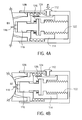
- FIGs. 4A and 4B are simplified, schematic, cross-sectional views of the lancing device of FIG. 1 depicting lance penetration into a relatively-low target site bulge and a relatively-high target site bulge, respectively;
- FIGs. 5A and 5B are simplified, schematic, cross-sectional views of the lancing device of FIG. 1 depicting post-lancing sample collection from a relatively-low target site bulge and a relatively-high target site bulge, respectively;
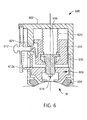
- FIG. 6 is a simplified, schematic, cross-sectional view of a lancing device according to another exemplary embodiment of the present invention.
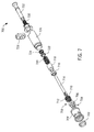
- FIG. 7 is an exploded perspective view of a lancing device according to yet another exemplary embodiment of the present invention.
- FIG. 8 is a simplified, schematic, cross-sectional view of the lancing device of FIG. 7;
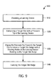
- FIG. 9 is a flow diagram illustrating a sequence of steps for lancing a target site according to the present invention.
- FIG. 1 is a simplified, schematic cross-sectional view of a lancing device 100 according to an exemplary embodiment of the present invention.
- Lancing device 100 includes a housing 102, a pressure tip 104, a lancing mechanism 106, floating probe 108, a floating probe spring 110 and a trigger button 112.
- pressure tip 104 is attached to housing 102.
- Pressure tip 104 and floating probe 108 are generally, but are not limited to being, cylindrical in form with openings (104a and 108a, respectively) therethrough.
- the openings within pressure tip 104 and floating probe 108 may be, but are not limited to, circular shape openings, square shape openings, triangular shape openings, C-shape openings, U-shape openings, hexagonal shape openings and an octagonal shape openings.
- pressure tip 104 is pressed against a target site (e.g., a user's skin of a dermal tissue target site) such that pressure tip 104 engages (contacts) the target site and urges the target site into a target-site bulge (not shown in FIG. 1) within the opening of pressure tip 104.
- a target site e.g., a user's skin of a dermal tissue target site
- Lancing mechanism 106 includes a lancet carriage 114, a lancet holder 116 and a lancet 118. Lancing mechanism 106 also includes over-travel spring 120 and launcher spring 122. Lancet carriage 114 includes carriage latch 124 and a lancet holder over-travel stop feature 126. In addition, pressure tip 104 has a probe stop surface 128.
- Floating probe 108 of lancing device 100 is adapted to floatably contact a target site bulge (not shown in FIG. 1) and is configured to operatively interact with lance carriage 114 to control a penetration depth of lancet 118 into the target-site bulge.
- the extent to which floating probe 108 can move is limited by floating probe spring 110 and probe stop surface 128.
- floating probe 108 In the embodiment of FIG. 1, the floating nature of floating probe 108 is due to floating probe 108 being slidable along a longitudinal axis of housing 102.
- lancet carriage 114 and lancet holder 116 are also slidable with respect to housing 102 along the same longitudinal axis.
- lancet holder 116 is slidably connected to lancet carriage 114.
- Over-travel spring 120, launcher spring 122 and probe spring 110 are configured to control movement and positioning of the floating probe, lancet carriage and lancet holder in a manner described below.
- Over-travel spring 120 and lancet holder over-travel stop feature 126 provide for lancet 118 to extend to a controlled penetration depth in a target site bulge before over-travel spring 120 returns lancet 118 to a fixed rest position.
- the position of lancet holder over-travel stop feature 126 with respect to a target site bulge is operatively set by the interaction of floating probe 108 and lancet carriage 114 (as described further below). Therefore, floating probe 108 is able to provide mechanical feedback to the lancet carriage 114, lancet holder 116 and lancet 118 such that the penetration depth across target site bulges of various heights is controlled and essentially constant.
- Launcher spring 122 controls movement of the lancet carriage 114.
- Floating probe spring 110 and the probe stop surface 128 serve to control the extent to which the floating probe 108 can move (i.e., float) relative to housing 102.
- Exemplary, but nonlimiting, strengths of the launcher spring 122, over-travel spring 120 and floating probe spring 110 are in the range of 0.5-1.0 lbs of force, 0.2-0.3 lbs of force and approximately 0.2 lbs of force respectively.
- Pressure tip 104 can be formed of, for example, a rigid or a relatively resiliently deformable material, including, but not limited, to elastomeric materials, polymeric materials, polyurethane materials, latex materials, silicone materials and any combinations thereof.
- Floating probe 108 can be formed of any suitable material including, but not limited to, relatively rigid material such as acrylonitrile butadiene styrene plastic, injection moldable plastic, polystyrene and metallic materials.
- FIG. 2 is a simplified schematic, cross-sectional view of lancing device 100 with the floating probe 108 and lancing mechanism 106 in the act of being placed into an armed position (e.g., immediately prior to use).
- the lancet carriage 114 In an armed position, the lancet carriage 114 is held in position against the biasing force of launcher spring 122 by interaction between carriage latch 124, housing 102 and trigger button 112.
- Lancing device 100 can, however, be placed into an armed position by any methods known to one skilled in the art including, for example, use of an external slider (not shown) or a plunger (also not shown).
- FIGs. 3A and 3B are simplified schematic, cross-sectional views of the lancing device of FIG. 1 with the floating probe contacting a relatively-low target site bulge (denoted as B1) and a relatively-high target site bulge (denoted as B2), respectively.
- B1 relatively-low target site bulge
- B2 relatively-high target site bulge
- FIGs. 3A and 3B are simplified schematic, cross-sectional views of the lancing device of FIG. 1 with the floating probe contacting a relatively-low target site bulge (denoted as B1) and a relatively-high target site bulge (denoted as B2), respectively.
- B1 and B2 relatively-low target site bulge
- B2 relatively-high target site bulge
- floating probe 108 is configured to move (i.e., float) with the surface of the target site bulge, essentially independent of lancet carriage 114 and housing 102. Since the floating probe floats with the surface of the target site bulge, floating probe 108 serves to control the penetration depth of lancet 118 into the target site bulge (as explained in more detail below).
- floating probe 108 can be configured to essentially float (rest) on the surface of the target site bulge in the presence of floating probe spring 110. This can be accomplished by, for example, selecting a floating probe spring with a spring constant that does not significantly interfere with the floating nature of the floating probe.
- FIGs. 4A and 4B are simplified, schematic, cross-sectional views of lancing device 100 depicting lance penetration into the relatively-low target site bulge B1 and the relatively-high target site bulges B2 of FIGs. 3A and 3B, respectively.
- carriage latch 124 allows lancet carriage 114, lancet holder 116 and lancet 118 to move (i.e., to be launched) toward the target site bulge under the force of launcher spring 122. Subsequently, lancet carriage 114 is stopped by contact with floating probe 108. The inertia of the lancet carriage may push the floating probe against the target site bulge, however this effect is a momentary deflection that is not expected to adversely affect operation of the lancing device.
- lancet holder 116 and lancet 118 Due to the inertia of lancet holder 116, lancet holder 116 and lancet 118 continue moving toward the target site bulge resulting in lancet 118 penetrating the target site bulge. This penetration is depicted in FIGs. 4A and 4B.
- Lancet holder over-travel stop feature 126 limits the distance that lancet holder 116 and lancet 118 can travel (to, for example, a distance in the range of 0.25 to 1.5 mm) once lancet carriage 114 has been stopped by contact with floating probe 108.
- the distance that lancet holder 116 and lancet 118 travel once lancet carriage 114 has been stopped is referred to as the over-travel distance. In the embodiment of FIGs. 1-5B, the over-travel distance is a fixed distance.
- FIGs. 5A and 5B are simplified, schematic, cross-sectional views of lancing device 100 depicting post-lancing sample collection from the relatively-low target site bulge B1 and a relatively-high target site bulge B2 of FIGs. 4A and 4B, respectively.
- the biasing force of over-travel spring 120 moves lancet holder 116 and lancet 118 to a position wherein lancet 118 is near or just below the surface of the target site bulge, e.g. to a depth of approximately 0.05 to 0.25 mm below the surface of the target site bulge.
- FIGs. 5A and 5B depict the presence of a biological fluid sample S (e.g., whole blood) that has been expressed from the target site bulge. This biological fluid sample is available for transfer to a test strip (not shown) for analyte detection.
- a biological fluid sample S e.g., whole blood
- FIG. 6 is a simplified, schematic, cross sectional view of a lancing device 600 according to another exemplary embodiment of the present invention.
- lancing device 600 is depicted in an armed position and as pressed against a target site bulge (TB).
- Lancing device 600 includes a housing 602, a pressure tip 604, a lancing mechanism 606, floating probe 608, floating probe spring 610 and a stop lock assembly 612 (with the dashed lines indicating a flexed position of stop lock assembly 612).
- Lancing mechanism 606 includes a lancet carriage 614, a lancet holder 616 and a lancet 618.
- Lancing mechanism 606 also includes launcher spring 620 and lancet carriage 614 includes a carriage latch 624.
- Pressure tip 604 of lancing device 600 is depicted as an elastomeric cap, such as the cap described in U.S. Provisional Patent Application No. 60/426,683, which is hereby fully incorporated herein by reference.
- any suitable pressure tip known to those of skill in the art can be employed in embodiments of lancing devices according to the present invention.
- Stop lock assembly 612 can be employed to prevent the floating probe 608 from moving after launching of the lancet carriage 614, thereby reducing the impact force between the lancet carriage and the floating probe. This is accomplished by pushing stop lock assembly 612 (in the direction of the arrow in FIG. 6) such that stop lock assembly teeth 612A engage floating probe 608. Once stop lock assembly teeth 612A have engaged floating probe 608, floating probe 608 is prevented from moving. Further pushing of stop lock assembly 612 places stop lock assembly into a flexed position (indicated by the dashed lines in FIG. 6) such that it can operatively interact with carriage latch 624.
- FIGs. 7 and 8 are perspective exploded and cross-sectional views, respectively, of a lancing device 700 according to another exemplary embodiment of the present invention.
- Lancing device 700 includes a pressure tip 702, front housing 704, floating probe 706, dowel pins 708, lancet 710, floating probe spring 712, lancet holder 714, rest adjust nut 716, lancet carriage 718, launcher spring 720, decoupling spring spacer 722, decoupling spring 724, rear housing 726, trigger button 728, over-travel spring 730 and plunger 732.
- Pressure tip 702 is illustrated as having the form of an elastomeric cap, such as the elastomeric cap described in U.S. Provisional Patent Application No. 60/426,683, which is fully incorporated herein by reference.
- decoupling spring 724 is operatively "in line” with the launcher spring 720. Therefore, decoupling spring 724 is functionally in series with the launcher spring 720.
- Decoupling spring 724 is selected to have a much lower spring load than the launcher spring 720.
- decoupling spring 724 can have a spring load at equilibrium in the range of 0.1 to 0.2 lbs.
- Decoupling spring 724 serves to reduce the cumulative force on floating probe 706. In the absence of decoupling spring 724, the spring force on floating probe 706 would be a result of the combined forces of floating probe spring 712 and the launcher spring 720. This combined force would cause an increase in the effective spring rate at the floating probe 706 that could adversely affect the operational characteristics of pressure tip 702.
- decoupling spring reduces the combined force and, therefore, eliminates such adverse affects. For example, when launcher spring 720 is extended during use, decoupling spring 724 acts to reduce the force applied by launcher spring 720 against lancet carriage 718.
- Lancing device 700 is configured such that it can be placed into an armed position by retraction of plunger pull 732.
- Trigger button 728 can, thereafter, be employed to initiate launching of lancet carriage 718 and lancet holder 714.
- Rest adjust nut 716 is adapted to adjust the lancet rest position, while dowel pins 708 are configured for locking floating probe 706 into a fixed position. Rest adjust nut 716 allows the user to adjust the post-launching rest position of the lancet 710 relative to the floating probe 706. This adjustment enables placement of the lancet tip in a position that facilitates the transfer of a sample onto a test strip (not shown) integrated with the lancet. Optimal placement of a lancet after lancing is described in more detail in US Provisional Application No. 60/422,228, which is hereby incorporated herein by reference.
- Depth penetration control with lancing device 700 is accomplished by having a threaded connection (not shown) between the plunger pull 732 and the lancet holder 714.
- the depth control or over-travel is limited when the plunger pull 732 contacts the lancet carriage 718.
- Over-travel spring 730 returns the lancet to the rest position after lancing is complete.
- the floating probe 706 can be locked into a fixed position by use of dowel pins 708. Placing the floating probe into a locked position disables the floating nature of the floating probe. However, such a locked position can be desirable when lancing device 700 is used to lance a target site that results in a relatively flat (i.e., essentially flat) target site bulge.
- the slots cut into front housing 704 can be designed to allow the floating probe 706 to move in an axial direction to a prescribed limit. Except as otherwise described or illustrated, lancing device 700 operates in essentially the same manner as that described with respect to the embodiment of FIGs. 1-5.
- lancet devices greatly facilitate reproducible production of a fluid sample (e.g., a blood sample) at a puncture (lancing) site because of the consistent lancet penetration depth.
- lancing device 700 was employed to lance various dermal tissue target sites (i.e., an index finger target site and a palm target site) that resulted in the creation of target site bulges of various heights. Although the height of the target site bulges differed by 3 mm to 4 mm, penetration depth was consistent, and a blood sample was successfully expressed, at each target site.
- a method 900 for lancing a target site includes providing a lancing device according to the present invention as described above.
- a lancing device includes a lancet carriage, a lancet holder slidably connected to the lancet carriage, a lancet attached to the lancet holder, a floating probe, and a pressure tip for engaging the target site and creating a target site bulge.
- the floating probe of such a lancing device is adapted to floatably contact the target site bulge and is configured to operatively interact with the lance carriage to control a penetration depth of the lancet into the target site bulge, as set forth in step 910.
- step 920 the pressure tip of the lancing device is contacted with the target site. Subsequently, the pressure tip is urged towards the target site, thereby creating target site bulge with the floating probe floating (resting) on a surface of the target site bulge, as set forth in step 930.
- the target site bulge is lanced with the lancet while the floating probe operatively interacts with the lance carriage to control a penetration depth of the lancet into the bulge, as set forth in step 940. If desired, movement of the floating probe during lancing can be prevented through the use of a stop lock assembly as described above.
- steps 910, 920, 930 and 940 have been effectively illustrated by FIGs. 2 through 4B above.
Abstract
Description
- The present invention relates, in general, to lancing devices and, in particular, to lancing devices with penetration depth control and associated methods of use.
- Conventional lancing devices generally have a rigid housing and a lancet that can be armed and launched so as to briefly protrude from one end of the lancing device. For example, conventional lancing devices can include a lancet that is mounted within a rigid housing such that the lancet is movable relative to the rigid housing along a longitudinal axis thereof. Typically, the lancet is spring loaded and launched, upon release of the spring, to penetrate (i.e., "lance") a target site (e.g., a dermal tissue target site). A biological fluid sample (e.g., a whole blood sample) can then be expressed from the penetrated target site for collection and analysis. Conventional lancing devices are described in U.S. Patent No. 5,730,753 to Morita, U.S. Patent No. 6,045,567 to Taylor et al. and U.S. Patent No. 6,071,250 to Douglas et al., each of which is incorporated fully herein by reference.
- Lancing devices often include a cap that engages the target site. Such a cap has an aperture (i.e., opening), through which the lancet protrudes during use. Typically, a distal end of the cap will be placed in contact with the target site during use. The profile of the distal end of the cap can be adapted for contact with predetermined target sites, such as fingers, earlobes, forearms and the abdomen.
- When a cap is contacted with a target site, pressure is usually applied to the target site prior to launch of the lancet. This pressure urges the cap against the target site and creates a target site bulge within the opening of the cap. The lancet is then launched to penetrate the target site bulge.
- When pressure is applied on a cap of a lancing device against a target site, however, the height of the resultant target site bulge can vary greatly depending on the dimensions of the cap's opening, the magnitude of applied pressure and various physical properties (e.g., elasticity) of the target site. Such variability in target site bulge height causes the penetration depth of the lancet into the target site bulge to vary, as well. Thus, a lancet can potentially penetrate too deeply in some circumstances and not deeply enough, or at all, in other circumstances. Still needed in the field, therefore, is a lancing device and associated method that provide for the control of penetration depth across target site bulges of various heights.
- Lancing devices and associated methods according to embodiments of the present invention provide for the control of penetration depth across target site bulges of various heights.
- A lancing device according to an exemplary embodiment of the present invention includes a lancing mechanism, a pressure tip and a floating probe. The lancing mechanism includes a lancet carriage, a lancet holder slidably connected to the lancet carriage, and a lancet attached to the lancet holder. The pressure tip is configured for engaging a target site and creating a target site bulge. The floating probe is adapted to floatably contact the target site bulge and to operatively interact with the lance carriage to control a penetration depth of the lancet into the target site bulge.
- Since the floating probe of lancing devices according to the present invention is adapted to float upon the target site bulge, the floating probe can provide mechanical feedback to the lance carriage, lancet holder and lancet such that the penetration depth across target site bulges of various heights is essentially constant. In doing so, the floating probe fixes a position of the lancet carriage relative to the target site bulge, thus providing a constant penetration depth.
- A method for lancing a target site according to an exemplary embodiment of the present invention includes providing a lancing device (according to the present invention as described herein) and contacting a pressure tip of the lancing device with the target site. The pressure tip is then urged towards the target site to create a target site bulge with a floating probe of the lancing device floating on a surface of the target site bulge. Next, the target site bulge is lanced while the floating probe operatively interacts with the lance carriage to control a penetration depth of the lancet.
- A better understanding of the features and advantages of the present invention will be obtained by reference to the following detailed description that sets forth illustrative embodiments, in which the principles of the invention are utilized, and the accompanying drawings, of which:
- FIG. 1 is a simplified, schematic, cross-sectional view of a lancing device according to an exemplary embodiment of the present invention, with a floating probe and a lancing mechanism of the lancing device in a rest position;
- FIG. 2 is a simplified schematic, cross-sectional view of the lancing device of FIG. 1 with the floating probe and lancing mechanism in the act of being placed into an armed position;
- FIGs. 3A and 3B are simplified schematic, cross-sectional views of the lancing device of FIG. 1 with the floating probe contacting a relatively-low target site bulge and a relatively-high target site bulge, respectively;
- FIGs. 4A and 4B are simplified, schematic, cross-sectional views of the lancing device of FIG. 1 depicting lance penetration into a relatively-low target site bulge and a relatively-high target site bulge, respectively;
- FIGs. 5A and 5B are simplified, schematic, cross-sectional views of the lancing device of FIG. 1 depicting post-lancing sample collection from a relatively-low target site bulge and a relatively-high target site bulge, respectively;
- FIG. 6 is a simplified, schematic, cross-sectional view of a lancing device according to another exemplary embodiment of the present invention;
- FIG. 7 is an exploded perspective view of a lancing device according to yet another exemplary embodiment of the present invention;
- FIG. 8 is a simplified, schematic, cross-sectional view of the lancing device of FIG. 7; and
- FIG. 9 is a flow diagram illustrating a sequence of steps for lancing a target site according to the present invention.
- FIG. 1 is a simplified, schematic cross-sectional view of a
lancing device 100 according to an exemplary embodiment of the present invention.Lancing device 100 includes ahousing 102, apressure tip 104, alancing mechanism 106, floatingprobe 108, afloating probe spring 110 and atrigger button 112. In the embodiment of FIG. 1,pressure tip 104 is attached tohousing 102. -
Pressure tip 104 andfloating probe 108 are generally, but are not limited to being, cylindrical in form with openings (104a and 108a, respectively) therethrough. The openings withinpressure tip 104 andfloating probe 108 may be, but are not limited to, circular shape openings, square shape openings, triangular shape openings, C-shape openings, U-shape openings, hexagonal shape openings and an octagonal shape openings. - During use of
lancing device 100,pressure tip 104 is pressed against a target site (e.g., a user's skin of a dermal tissue target site) such thatpressure tip 104 engages (contacts) the target site and urges the target site into a target-site bulge (not shown in FIG. 1) within the opening ofpressure tip 104. -
Lancing mechanism 106 includes alancet carriage 114, alancet holder 116 and alancet 118.Lancing mechanism 106 also includes over-travelspring 120 andlauncher spring 122. Lancetcarriage 114 includescarriage latch 124 and a lancet holder over-travelstop feature 126. In addition,pressure tip 104 has aprobe stop surface 128. - Floating
probe 108 oflancing device 100 is adapted to floatably contact a target site bulge (not shown in FIG. 1) and is configured to operatively interact withlance carriage 114 to control a penetration depth oflancet 118 into the target-site bulge. However, the extent to which floatingprobe 108 can move is limited by floatingprobe spring 110 andprobe stop surface 128. - In the embodiment of FIG. 1, the floating nature of
floating probe 108 is due to floatingprobe 108 being slidable along a longitudinal axis ofhousing 102. In addition,lancet carriage 114 andlancet holder 116 are also slidable with respect tohousing 102 along the same longitudinal axis. Furthermore,lancet holder 116 is slidably connected tolancet carriage 114. - Over-travel
spring 120,launcher spring 122 andprobe spring 110 are configured to control movement and positioning of the floating probe, lancet carriage and lancet holder in a manner described below. - Over-travel
spring 120 and lancet holder over-travelstop feature 126 provide forlancet 118 to extend to a controlled penetration depth in a target site bulge before over-travelspring 120 returns lancet 118 to a fixed rest position. In this regard, it should be noted that the position of lancet holder over-travelstop feature 126 with respect to a target site bulge is operatively set by the interaction of floatingprobe 108 and lancet carriage 114 (as described further below). Therefore, floatingprobe 108 is able to provide mechanical feedback to thelancet carriage 114,lancet holder 116 andlancet 118 such that the penetration depth across target site bulges of various heights is controlled and essentially constant. -
Launcher spring 122 controls movement of thelancet carriage 114. Floatingprobe spring 110 and theprobe stop surface 128 serve to control the extent to which the floatingprobe 108 can move (i.e., float) relative tohousing 102. Exemplary, but nonlimiting, strengths of thelauncher spring 122,over-travel spring 120 and floatingprobe spring 110 are in the range of 0.5-1.0 lbs of force, 0.2-0.3 lbs of force and approximately 0.2 lbs of force respectively. -
Pressure tip 104 can be formed of, for example, a rigid or a relatively resiliently deformable material, including, but not limited, to elastomeric materials, polymeric materials, polyurethane materials, latex materials, silicone materials and any combinations thereof. Floatingprobe 108 can be formed of any suitable material including, but not limited to, relatively rigid material such as acrylonitrile butadiene styrene plastic, injection moldable plastic, polystyrene and metallic materials. - The operation and various features of lancing
device 100 are illustrated in FIGs. 2, 3A, 3B, 4A, 4B, 5A and 5B. FIG. 2 is a simplified schematic, cross-sectional view of lancingdevice 100 with the floatingprobe 108 and lancingmechanism 106 in the act of being placed into an armed position (e.g., immediately prior to use). In an armed position, thelancet carriage 114 is held in position against the biasing force oflauncher spring 122 by interaction betweencarriage latch 124,housing 102 andtrigger button 112. The arrows of FIG. 2 depict a direction in which floatingprobe 108 can be pushed in order to placelancet carriage 114 into a position where it is held against the biasing force oflauncher spring 122 by interaction betweencarriage latch 124,housing 102 and trigger button 112 (i.e., into an armed position). Lancingdevice 100 can, however, be placed into an armed position by any methods known to one skilled in the art including, for example, use of an external slider (not shown) or a plunger (also not shown). - FIGs. 3A and 3B are simplified schematic, cross-sectional views of the lancing device of FIG. 1 with the floating probe contacting a relatively-low target site bulge (denoted as B1) and a relatively-high target site bulge (denoted as B2), respectively. When lancing
device 100 is in use andpressure tip 104 is applied against a target site, a target site bulge is created in the opening ofpressure tip 104. The height of the target site bulge can vary depending on, for example, target site physical properties. However, in both FIG. 3A and FIG. 3B, floatingprobe 108 rests upon the target site bulge (B1 and B2, respectively in the FIGs. 3A and 3B) and is configured to move (i.e., float) with the surface of the target site bulge, essentially independent oflancet carriage 114 andhousing 102. Since the floating probe floats with the surface of the target site bulge, floatingprobe 108 serves to control the penetration depth oflancet 118 into the target site bulge (as explained in more detail below). One skilled in the art will recognize that floatingprobe 108 can be configured to essentially float (rest) on the surface of the target site bulge in the presence of floatingprobe spring 110. This can be accomplished by, for example, selecting a floating probe spring with a spring constant that does not significantly interfere with the floating nature of the floating probe. - FIGs. 4A and 4B are simplified, schematic, cross-sectional views of lancing
device 100 depicting lance penetration into the relatively-low target site bulge B1 and the relatively-high target site bulges B2 of FIGs. 3A and 3B, respectively. Oncepressure tip 104 has been applied to a target site and a target site bulge created, operation of trigger button 112 (depicted by the arrow in FIG. 4A) releasescarriage latch 124. - Release of
carriage latch 124 allowslancet carriage 114,lancet holder 116 andlancet 118 to move (i.e., to be launched) toward the target site bulge under the force oflauncher spring 122. Subsequently,lancet carriage 114 is stopped by contact with floatingprobe 108. The inertia of the lancet carriage may push the floating probe against the target site bulge, however this effect is a momentary deflection that is not expected to adversely affect operation of the lancing device. - Due to the inertia of
lancet holder 116,lancet holder 116 andlancet 118 continue moving toward the target site bulge resulting inlancet 118 penetrating the target site bulge. This penetration is depicted in FIGs. 4A and 4B. Lancet holder over-travel stop feature 126 limits the distance thatlancet holder 116 andlancet 118 can travel (to, for example, a distance in the range of 0.25 to 1.5 mm) oncelancet carriage 114 has been stopped by contact with floatingprobe 108. The distance thatlancet holder 116 andlancet 118 travel oncelancet carriage 114 has been stopped is referred to as the over-travel distance. In the embodiment of FIGs. 1-5B, the over-travel distance is a fixed distance. - Since the floating probe rests upon the surface of the target site bulge, regardless of whether the target site bulge is relatively high or relatively low, and serves to stop the movement of
lancet carriage 114, penetration depth is consistently controlled across various target site bulge heights. - FIGs. 5A and 5B are simplified, schematic, cross-sectional views of lancing
device 100 depicting post-lancing sample collection from the relatively-low target site bulge B1 and a relatively-high target site bulge B2 of FIGs. 4A and 4B, respectively. Following penetration of the target site bulge by lancet 118 (as depicted in FIGs. 4A and 4B), the biasing force ofover-travel spring 120 moveslancet holder 116 andlancet 118 to a position whereinlancet 118 is near or just below the surface of the target site bulge, e.g. to a depth of approximately 0.05 to 0.25 mm below the surface of the target site bulge. FIGs. 5A and 5B depict the presence of a biological fluid sample S (e.g., whole blood) that has been expressed from the target site bulge. This biological fluid sample is available for transfer to a test strip (not shown) for analyte detection. - FIG. 6 is a simplified, schematic, cross sectional view of a lancing
device 600 according to another exemplary embodiment of the present invention. In FIG. 6, lancingdevice 600 is depicted in an armed position and as pressed against a target site bulge (TB). Lancingdevice 600 includes ahousing 602, apressure tip 604, a lancing mechanism 606, floatingprobe 608, floatingprobe spring 610 and a stop lock assembly 612 (with the dashed lines indicating a flexed position of stop lock assembly 612). - Lancing mechanism 606 includes a
lancet carriage 614, alancet holder 616 and alancet 618. Lancing mechanism 606 also includeslauncher spring 620 andlancet carriage 614 includes acarriage latch 624. -
Pressure tip 604 of lancingdevice 600 is depicted as an elastomeric cap, such as the cap described in U.S. Provisional Patent Application No. 60/426,683, which is hereby fully incorporated herein by reference. However, any suitable pressure tip known to those of skill in the art can be employed in embodiments of lancing devices according to the present invention. - Stop
lock assembly 612 can be employed to prevent the floatingprobe 608 from moving after launching of thelancet carriage 614, thereby reducing the impact force between the lancet carriage and the floating probe. This is accomplished by pushing stop lock assembly 612 (in the direction of the arrow in FIG. 6) such that stop lock assembly teeth 612A engage floatingprobe 608. Once stop lock assembly teeth 612A have engaged floatingprobe 608, floatingprobe 608 is prevented from moving. Further pushing ofstop lock assembly 612 places stop lock assembly into a flexed position (indicated by the dashed lines in FIG. 6) such that it can operatively interact withcarriage latch 624. - FIGs. 7 and 8 are perspective exploded and cross-sectional views, respectively, of a lancing
device 700 according to another exemplary embodiment of the present invention. Lancingdevice 700 includes apressure tip 702,front housing 704, floatingprobe 706, dowel pins 708,lancet 710, floatingprobe spring 712,lancet holder 714, rest adjustnut 716,lancet carriage 718,launcher spring 720,decoupling spring spacer 722,decoupling spring 724,rear housing 726,trigger button 728,over-travel spring 730 andplunger 732. -
Pressure tip 702 is illustrated as having the form of an elastomeric cap, such as the elastomeric cap described in U.S. Provisional Patent Application No. 60/426,683, which is fully incorporated herein by reference. In the embodiment of FIGs. 7 and 8,decoupling spring 724 is operatively "in line" with thelauncher spring 720. Therefore,decoupling spring 724 is functionally in series with thelauncher spring 720. -
Decoupling spring 724 is selected to have a much lower spring load than thelauncher spring 720. For example,decoupling spring 724 can have a spring load at equilibrium in the range of 0.1 to 0.2 lbs.Decoupling spring 724 serves to reduce the cumulative force on floatingprobe 706. In the absence ofdecoupling spring 724, the spring force on floatingprobe 706 would be a result of the combined forces of floatingprobe spring 712 and thelauncher spring 720. This combined force would cause an increase in the effective spring rate at the floatingprobe 706 that could adversely affect the operational characteristics ofpressure tip 702. However, decoupling spring reduces the combined force and, therefore, eliminates such adverse affects. For example, whenlauncher spring 720 is extended during use,decoupling spring 724 acts to reduce the force applied bylauncher spring 720 againstlancet carriage 718. - Lancing
device 700 is configured such that it can be placed into an armed position by retraction ofplunger pull 732.Trigger button 728 can, thereafter, be employed to initiate launching oflancet carriage 718 andlancet holder 714. - Rest adjust
nut 716 is adapted to adjust the lancet rest position, while dowel pins 708 are configured for locking floatingprobe 706 into a fixed position. Rest adjustnut 716 allows the user to adjust the post-launching rest position of thelancet 710 relative to the floatingprobe 706. This adjustment enables placement of the lancet tip in a position that facilitates the transfer of a sample onto a test strip (not shown) integrated with the lancet. Optimal placement of a lancet after lancing is described in more detail in US Provisional Application No. 60/422,228, which is hereby incorporated herein by reference. - Depth penetration control with lancing
device 700 is accomplished by having a threaded connection (not shown) between the plunger pull 732 and thelancet holder 714. The depth control or over-travel is limited when the plunger pull 732 contacts thelancet carriage 718. By adjusting the gap between the plunger pull 732 and thelancet carriage 718, lancet depth control is achieved.Over-travel spring 730 returns the lancet to the rest position after lancing is complete. - The floating
probe 706 can be locked into a fixed position by use of dowel pins 708. Placing the floating probe into a locked position disables the floating nature of the floating probe. However, such a locked position can be desirable when lancingdevice 700 is used to lance a target site that results in a relatively flat (i.e., essentially flat) target site bulge. One skilled in the art will also appreciate that the slots cut intofront housing 704 can be designed to allow the floatingprobe 706 to move in an axial direction to a prescribed limit. Except as otherwise described or illustrated, lancingdevice 700 operates in essentially the same manner as that described with respect to the embodiment of FIGs. 1-5. - As will be appreciated by those skilled in the art, lancet devices according to the present invention greatly facilitate reproducible production of a fluid sample (e.g., a blood sample) at a puncture (lancing) site because of the consistent lancet penetration depth. For example, lancing
device 700 was employed to lance various dermal tissue target sites (i.e., an index finger target site and a palm target site) that resulted in the creation of target site bulges of various heights. Although the height of the target site bulges differed by 3 mm to 4 mm, penetration depth was consistent, and a blood sample was successfully expressed, at each target site. This facilitates in-situ testing of a fluid sample by means of a fluid collection device (such as a test strip) that is introduced at the lancet penetration site just after a lancet has been retracted. Consistent proper lancet depth control can also result in less pain. - Referring to FIG. 9, a
method 900 for lancing a target site includes providing a lancing device according to the present invention as described above. Such a lancing device includes a lancet carriage, a lancet holder slidably connected to the lancet carriage, a lancet attached to the lancet holder, a floating probe, and a pressure tip for engaging the target site and creating a target site bulge. The floating probe of such a lancing device is adapted to floatably contact the target site bulge and is configured to operatively interact with the lance carriage to control a penetration depth of the lancet into the target site bulge, as set forth instep 910. - Next, at
step 920, the pressure tip of the lancing device is contacted with the target site. Subsequently, the pressure tip is urged towards the target site, thereby creating target site bulge with the floating probe floating (resting) on a surface of the target site bulge, as set forth instep 930. - Next, the target site bulge is lanced with the lancet while the floating probe operatively interacts with the lance carriage to control a penetration depth of the lancet into the bulge, as set forth in
step 940. If desired, movement of the floating probe during lancing can be prevented through the use of a stop lock assembly as described above. One skilled in the art will recognize thatsteps - It should be understood that various alternatives to the embodiments of the invention described herein may be employed in practicing the invention. It is intended that the following claims define the scope of the invention and that methods and structures within the scope of these claims and their equivalents be covered thereby.
Claims (11)
- A lancing device comprising:wherein the floating probe is adapted to floatably contact said target site bulge and is configured to operatively interact with the lance carriage to control a penetration depth of the lancet into the bulge.a lancing mechanism having:a lancet carriage;a lancet holder slidably connected to the lancet carriage; anda lancet attached to the lancet holder;a floating probe; anda pressure tip for engaging a target site and creating a target site bulge;
- The lancing device of claim 1 further comprising:wherein the lancet carriage is slidably connected to the housing, the lancet holder is slidably connected to the lancet carriage and the floating probe is slidably connected to the housing.a housing;
- The lancing device of claim 2, wherein the lancing mechanism further includes an over-travel spring and a launcher spring, wherein the housing includes a floating probe spring, and wherein the floating probe spring, launcher spring and floating probe spring are configured to control movement and positioning of the floating probe, lancet carriage and lancet holder.
- The lancing device of any preceding claim, wherein the floating probe is formed from a rigid material.
- The lancing device of any preceding claim, further comprising a launcher spring and a decoupling spring arranged in series.
- The lancing device of any preceding claim, wherein the penetration depth is in the range of 0.25 to 1.5 mm.
- The lancing device of any preceding claim further comprising a stop lock assembly.
- The lancing device of any preceding claim, wherein the pressure tip includes a probe stop surface.
- The lancing device of any preceding claim, wherein the lancet carriage includes a lancet holder over-travel stop feature.
- A method for lancing a target site, the method comprising:wherein the floating probe is adapted to floatably contact said target site bulge and is configured to operatively interact with the lance carriage to control a penetration depth of the lancet into the bulge;providing a lancing device that includes:a lancet carriage;a lancet holder slidably connected to the lancet carriage; anda lancet attached to the lancet holder;a floating probe; anda pressure tip for engaging a target site and creating a target site bulge;
contacting the pressure tip with the target site;
urging the pressure tip towards the target site, thereby creating target site bulge such that the floating probe is floating on a surface of the target site bulge; and
lancing the target site bulge with the lancet while the floating probe operatively interacts with the lance carriage to control a penetration of the lancet. - The method of claim 10, wherein the providing step provides a lancing device that further includes a stop lock assembly and wherein the lancing step lances the target site bulge while the stop lock assembly prevents movement of the floating probe.
Applications Claiming Priority (2)
| Application Number | Priority Date | Filing Date | Title |
|---|---|---|---|
| US690083 | 2003-10-20 | ||
| US10/690,083 US7481818B2 (en) | 2003-10-20 | 2003-10-20 | Lancing device with a floating probe for control of penetration depth |
Publications (2)
| Publication Number | Publication Date |
|---|---|
| EP1527736A1 true EP1527736A1 (en) | 2005-05-04 |
| EP1527736B1 EP1527736B1 (en) | 2009-08-12 |
Family
ID=34423316
Family Applications (1)
| Application Number | Title | Priority Date | Filing Date |
|---|---|---|---|
| EP04256423A Not-in-force EP1527736B1 (en) | 2003-10-20 | 2004-10-19 | Lancing device with a floating probe for control of penetration depth |
Country Status (17)
| Country | Link |
|---|---|
| US (1) | US7481818B2 (en) |
| EP (1) | EP1527736B1 (en) |
| JP (1) | JP4727204B2 (en) |
| KR (1) | KR101157812B1 (en) |
| CN (1) | CN1608587B (en) |
| AT (1) | ATE439083T1 (en) |
| AU (1) | AU2004222739B2 (en) |
| CA (1) | CA2485394C (en) |
| DE (1) | DE602004022497D1 (en) |
| ES (1) | ES2329900T3 (en) |
| HK (1) | HK1073057A1 (en) |
| IL (1) | IL164696A (en) |
| MX (1) | MXPA04010359A (en) |
| NO (1) | NO20044435L (en) |
| RU (1) | RU2343831C2 (en) |
| SG (2) | SG131939A1 (en) |
| TW (1) | TWI374728B (en) |
Cited By (1)
| Publication number | Priority date | Publication date | Assignee | Title |
|---|---|---|---|---|
| EP1897493A1 (en) * | 2006-09-04 | 2008-03-12 | Roche Diagnostics GmbH | Piercing system for withdrawing a bodily fluid |
Families Citing this family (110)
| Publication number | Priority date | Publication date | Assignee | Title |
|---|---|---|---|---|
| US6036924A (en) | 1997-12-04 | 2000-03-14 | Hewlett-Packard Company | Cassette of lancet cartridges for sampling blood |
| US6391005B1 (en) | 1998-03-30 | 2002-05-21 | Agilent Technologies, Inc. | Apparatus and method for penetration with shaft having a sensor for sensing penetration depth |
| US8641644B2 (en) | 2000-11-21 | 2014-02-04 | Sanofi-Aventis Deutschland Gmbh | Blood testing apparatus having a rotatable cartridge with multiple lancing elements and testing means |
| US9226699B2 (en) | 2002-04-19 | 2016-01-05 | Sanofi-Aventis Deutschland Gmbh | Body fluid sampling module with a continuous compression tissue interface surface |
| EP1404234B1 (en) | 2001-06-12 | 2011-02-09 | Pelikan Technologies Inc. | Apparatus for improving success rate of blood yield from a fingerstick |
| US7981056B2 (en) | 2002-04-19 | 2011-07-19 | Pelikan Technologies, Inc. | Methods and apparatus for lancet actuation |
| US9427532B2 (en) | 2001-06-12 | 2016-08-30 | Sanofi-Aventis Deutschland Gmbh | Tissue penetration device |
| ATE485766T1 (en) | 2001-06-12 | 2010-11-15 | Pelikan Technologies Inc | ELECTRICAL ACTUATING ELEMENT FOR A LANCET |
| US7025774B2 (en) | 2001-06-12 | 2006-04-11 | Pelikan Technologies, Inc. | Tissue penetration device |
| DE60234598D1 (en) | 2001-06-12 | 2010-01-14 | Pelikan Technologies Inc | SELF-OPTIMIZING LANZET DEVICE WITH ADAPTANT FOR TEMPORAL FLUCTUATIONS OF SKIN PROPERTIES |
| US8337419B2 (en) | 2002-04-19 | 2012-12-25 | Sanofi-Aventis Deutschland Gmbh | Tissue penetration device |
| US7682318B2 (en) | 2001-06-12 | 2010-03-23 | Pelikan Technologies, Inc. | Blood sampling apparatus and method |
| US7749174B2 (en) | 2001-06-12 | 2010-07-06 | Pelikan Technologies, Inc. | Method and apparatus for lancet launching device intergrated onto a blood-sampling cartridge |
| US9795747B2 (en) | 2010-06-02 | 2017-10-24 | Sanofi-Aventis Deutschland Gmbh | Methods and apparatus for lancet actuation |
| US8360992B2 (en) | 2002-04-19 | 2013-01-29 | Sanofi-Aventis Deutschland Gmbh | Method and apparatus for penetrating tissue |
| US8702624B2 (en) | 2006-09-29 | 2014-04-22 | Sanofi-Aventis Deutschland Gmbh | Analyte measurement device with a single shot actuator |
| US7175642B2 (en) | 2002-04-19 | 2007-02-13 | Pelikan Technologies, Inc. | Methods and apparatus for lancet actuation |
| US7547287B2 (en) | 2002-04-19 | 2009-06-16 | Pelikan Technologies, Inc. | Method and apparatus for penetrating tissue |
| US7297122B2 (en) | 2002-04-19 | 2007-11-20 | Pelikan Technologies, Inc. | Method and apparatus for penetrating tissue |
| US7232451B2 (en) | 2002-04-19 | 2007-06-19 | Pelikan Technologies, Inc. | Method and apparatus for penetrating tissue |
| US7901362B2 (en) | 2002-04-19 | 2011-03-08 | Pelikan Technologies, Inc. | Method and apparatus for penetrating tissue |
| US9795334B2 (en) | 2002-04-19 | 2017-10-24 | Sanofi-Aventis Deutschland Gmbh | Method and apparatus for penetrating tissue |
| US7229458B2 (en) | 2002-04-19 | 2007-06-12 | Pelikan Technologies, Inc. | Method and apparatus for penetrating tissue |
| US7892185B2 (en) | 2002-04-19 | 2011-02-22 | Pelikan Technologies, Inc. | Method and apparatus for body fluid sampling and analyte sensing |
| US7291117B2 (en) | 2002-04-19 | 2007-11-06 | Pelikan Technologies, Inc. | Method and apparatus for penetrating tissue |
| US7371247B2 (en) | 2002-04-19 | 2008-05-13 | Pelikan Technologies, Inc | Method and apparatus for penetrating tissue |
| US7648468B2 (en) | 2002-04-19 | 2010-01-19 | Pelikon Technologies, Inc. | Method and apparatus for penetrating tissue |
| US7909778B2 (en) | 2002-04-19 | 2011-03-22 | Pelikan Technologies, Inc. | Method and apparatus for penetrating tissue |
| US7717863B2 (en) | 2002-04-19 | 2010-05-18 | Pelikan Technologies, Inc. | Method and apparatus for penetrating tissue |
| US9314194B2 (en) | 2002-04-19 | 2016-04-19 | Sanofi-Aventis Deutschland Gmbh | Tissue penetration device |
| US7331931B2 (en) | 2002-04-19 | 2008-02-19 | Pelikan Technologies, Inc. | Method and apparatus for penetrating tissue |
| US8221334B2 (en) | 2002-04-19 | 2012-07-17 | Sanofi-Aventis Deutschland Gmbh | Method and apparatus for penetrating tissue |
| US7491178B2 (en) | 2002-04-19 | 2009-02-17 | Pelikan Technologies, Inc. | Method and apparatus for penetrating tissue |
| US8579831B2 (en) | 2002-04-19 | 2013-11-12 | Sanofi-Aventis Deutschland Gmbh | Method and apparatus for penetrating tissue |
| US8784335B2 (en) | 2002-04-19 | 2014-07-22 | Sanofi-Aventis Deutschland Gmbh | Body fluid sampling device with a capacitive sensor |
| US7674232B2 (en) | 2002-04-19 | 2010-03-09 | Pelikan Technologies, Inc. | Method and apparatus for penetrating tissue |
| US8267870B2 (en) | 2002-04-19 | 2012-09-18 | Sanofi-Aventis Deutschland Gmbh | Method and apparatus for body fluid sampling with hybrid actuation |
| US9248267B2 (en) | 2002-04-19 | 2016-02-02 | Sanofi-Aventis Deustchland Gmbh | Tissue penetration device |
| US7226461B2 (en) | 2002-04-19 | 2007-06-05 | Pelikan Technologies, Inc. | Method and apparatus for a multi-use body fluid sampling device with sterility barrier release |
| US7976476B2 (en) | 2002-04-19 | 2011-07-12 | Pelikan Technologies, Inc. | Device and method for variable speed lancet |
| US7892183B2 (en) | 2002-04-19 | 2011-02-22 | Pelikan Technologies, Inc. | Method and apparatus for body fluid sampling and analyte sensing |
| CN100360086C (en) * | 2002-11-15 | 2008-01-09 | 爱科来株式会社 | Lancet and needle insertion device |
| US20040127818A1 (en) * | 2002-12-27 | 2004-07-01 | Roe Steven N. | Precision depth control lancing tip |
| US8574895B2 (en) | 2002-12-30 | 2013-11-05 | Sanofi-Aventis Deutschland Gmbh | Method and apparatus using optical techniques to measure analyte levels |
| EP1628567B1 (en) | 2003-05-30 | 2010-08-04 | Pelikan Technologies Inc. | Method and apparatus for fluid injection |
| DK1633235T3 (en) | 2003-06-06 | 2014-08-18 | Sanofi Aventis Deutschland | Apparatus for sampling body fluid and detecting analyte |
| WO2006001797A1 (en) | 2004-06-14 | 2006-01-05 | Pelikan Technologies, Inc. | Low pain penetrating |
| US7920906B2 (en) | 2005-03-10 | 2011-04-05 | Dexcom, Inc. | System and methods for processing analyte sensor data for sensor calibration |
| US8282576B2 (en) | 2003-09-29 | 2012-10-09 | Sanofi-Aventis Deutschland Gmbh | Method and apparatus for an improved sample capture device |
| EP1680014A4 (en) | 2003-10-14 | 2009-01-21 | Pelikan Technologies Inc | Method and apparatus for a variable user interface |
| US20050096686A1 (en) * | 2003-10-31 | 2005-05-05 | Allen John J. | Lancing device with trigger mechanism for penetration depth control |
| US9247900B2 (en) | 2004-07-13 | 2016-02-02 | Dexcom, Inc. | Analyte sensor |
| EP1706026B1 (en) | 2003-12-31 | 2017-03-01 | Sanofi-Aventis Deutschland GmbH | Method and apparatus for improving fluidic flow and sample capture |
| US7822454B1 (en) | 2005-01-03 | 2010-10-26 | Pelikan Technologies, Inc. | Fluid sampling device with improved analyte detecting member configuration |
| US7798978B2 (en) * | 2004-03-15 | 2010-09-21 | Terumo Kabushiki Kaisha | Body fluid collecting device |
| US7201723B2 (en) * | 2004-03-25 | 2007-04-10 | Roche Diagnostics Operations, Inc. | Pulsating expression cap |
| CA2562215A1 (en) | 2004-04-10 | 2005-10-20 | F. Hoffmann-La Roche Ag | Method and system for taking body fluid |
| US8792955B2 (en) | 2004-05-03 | 2014-07-29 | Dexcom, Inc. | Transcutaneous analyte sensor |
| US8828203B2 (en) | 2004-05-20 | 2014-09-09 | Sanofi-Aventis Deutschland Gmbh | Printable hydrogels for biosensors |
| EP1765194A4 (en) | 2004-06-03 | 2010-09-29 | Pelikan Technologies Inc | Method and apparatus for a fluid sampling device |
| US9775553B2 (en) | 2004-06-03 | 2017-10-03 | Sanofi-Aventis Deutschland Gmbh | Method and apparatus for a fluid sampling device |
| US20050277849A1 (en) * | 2004-06-10 | 2005-12-15 | Daniel Wong | Vacuum sample expression device |
| US20060036187A1 (en) | 2004-06-30 | 2006-02-16 | Hester Vos | Devices, systems and methods for extracting bodily fluid and monitoring an analyte therein |
| WO2006127694A2 (en) | 2004-07-13 | 2006-11-30 | Dexcom, Inc. | Analyte sensor |
| US7946984B2 (en) | 2004-07-13 | 2011-05-24 | Dexcom, Inc. | Transcutaneous analyte sensor |
| US7727166B2 (en) * | 2004-07-26 | 2010-06-01 | Nova Biomedical Corporation | Lancet, lancet assembly and lancet-sensor combination |
| DE102004059491B4 (en) * | 2004-12-10 | 2008-11-06 | Roche Diagnostics Gmbh | Lancet device for creating a puncture wound and lancet drive assembly |
| US8652831B2 (en) | 2004-12-30 | 2014-02-18 | Sanofi-Aventis Deutschland Gmbh | Method and apparatus for analyte measurement test time |
| US8956291B2 (en) | 2005-02-22 | 2015-02-17 | Admetsys Corporation | Balanced physiological monitoring and treatment system |
| CN101146477B (en) * | 2005-03-03 | 2012-11-07 | 霍夫曼-拉罗奇有限公司 | Piercing system for removing a bodily fluid |
| EP1709906A1 (en) * | 2005-04-07 | 2006-10-11 | F. Hoffmann-La Roche Ag | Method and device for blood sampling |
| US20070038148A1 (en) * | 2005-08-11 | 2007-02-15 | Joel Mechelke | Sampling module for extracting interstitial fluid |
| JP4575257B2 (en) * | 2005-09-06 | 2010-11-04 | オリンパスメディカルシステムズ株式会社 | Tissue biopsy needle device |
| US20070202186A1 (en) | 2006-02-22 | 2007-08-30 | Iscience Interventional Corporation | Apparatus and formulations for suprachoroidal drug delivery |
| WO2007130830A2 (en) | 2006-04-25 | 2007-11-15 | Facet Technologies, Llc | Lancing device with independent drive core |
| US7909842B2 (en) * | 2006-06-15 | 2011-03-22 | Abbott Diabetes Care Inc. | Lancing devices having depth adjustment assembly |
| US7824102B2 (en) * | 2006-12-09 | 2010-11-02 | Shenzhen Mindray Bio-Medical Electronics, Inc. | Thermometer quick linkage apparatus and method |
| WO2009126900A1 (en) | 2008-04-11 | 2009-10-15 | Pelikan Technologies, Inc. | Method and apparatus for analyte detecting device |
| US20090264911A1 (en) * | 2008-04-16 | 2009-10-22 | Kim Stanley I | Single-use disposable lancing apparatus and methods |
| WO2010011805A1 (en) * | 2008-07-24 | 2010-01-28 | Admetsys Corporation | Device and method for automatically sampling and measuring blood analytes |
| US8123772B2 (en) * | 2008-08-14 | 2012-02-28 | Abbott Diabetes Care Inc. | Cap for lancing device with adjustable mode of operation |
| US8092476B2 (en) * | 2008-08-14 | 2012-01-10 | Abbott Diabetes Care Inc. | Adjustable cap and lancing device and method of use |
| EP2181651A1 (en) * | 2008-10-29 | 2010-05-05 | Roche Diagnostics GmbH | Instrument and system for producing a sample of a body liquid and for analysis thereof |
| JPWO2010050350A1 (en) * | 2008-10-30 | 2012-03-29 | シスメックス株式会社 | Body fluid collecting device and puncture needle attaching / detaching member used in this device |
| US9375169B2 (en) | 2009-01-30 | 2016-06-28 | Sanofi-Aventis Deutschland Gmbh | Cam drive for managing disposable penetrating member actions with a single motor and motor and control system |
| JP5366195B2 (en) * | 2009-01-30 | 2013-12-11 | テルモ株式会社 | Injection needle assembly and drug injection device |
| KR101120364B1 (en) * | 2009-06-30 | 2012-02-24 | 변남철 | Lancing device for blood-gathering |
| WO2011002229A2 (en) * | 2009-06-30 | 2011-01-06 | Byun Nam Chul | Blood collecting device |
| NZ714959A (en) * | 2009-10-16 | 2016-09-30 | Janssen Biotech Inc | Palm activated drug delivery device |
| US9233213B2 (en) | 2009-10-16 | 2016-01-12 | Janssen Biotech, Inc. | Palm activated drug delivery device |
| CN106137528B (en) * | 2010-03-31 | 2020-12-01 | 奥库杰克特有限责任公司 | Apparatus and method for intraocular drug delivery |
| US8965476B2 (en) | 2010-04-16 | 2015-02-24 | Sanofi-Aventis Deutschland Gmbh | Tissue penetration device |
| WO2011152580A1 (en) * | 2010-06-04 | 2011-12-08 | Shin Youn-Cheol | Device for preventing reuse of lancet |
| BR112013000086A2 (en) | 2010-07-02 | 2016-05-10 | Sanofi Aventis Deutschland | safety device for a filled syringe and injection device |
| CN203815532U (en) * | 2011-03-09 | 2014-09-10 | 贝克顿·迪金森公司 | Lancet box assembly for blood sampling apparatus and blood sampling apparatus |
| JP5930688B2 (en) * | 2011-12-09 | 2016-06-08 | アークレイ株式会社 | Lancet cartridge |
| DE102011056626B4 (en) * | 2011-12-19 | 2014-02-13 | Gerresheimer Regensburg Gmbh | Lancing device for blood sampling |
| EP2836124B1 (en) | 2012-04-11 | 2016-06-08 | Facet Technologies, LLC | Lancing device with moving pivot depth adjust |
| JP5932991B2 (en) * | 2012-05-18 | 2016-06-08 | パナソニックヘルスケアホールディングス株式会社 | Puncture needle cartridge |
| BR112014031135A2 (en) * | 2012-06-12 | 2017-06-27 | T Medical Innovations Ltd | device for producing a skin incision in surgical procedures and marking near the edges of the incision |
| WO2014014235A1 (en) * | 2012-07-18 | 2014-01-23 | Park Jin Han | Blood-collection device |
| US10646150B2 (en) * | 2013-03-12 | 2020-05-12 | Ascensia Diabetes Care Holdings Ag | Lancing device |
| CN104127190A (en) * | 2013-05-03 | 2014-11-05 | 品强科技精密有限公司 | Blood sampling device allowing controllable puncturing depth |
| AU2014259694B2 (en) | 2013-05-03 | 2018-11-08 | Clearside Biomedical, Inc. | Apparatus and methods for ocular injection |
| CN105771038B (en) * | 2016-03-17 | 2022-09-13 | 南京医科大学第一附属医院 | Accurate trace acupuncture point injection pen |
| JP2019514581A (en) | 2016-05-02 | 2019-06-06 | クリアサイド バイオメディカル,インコーポレイテッド | Systems and methods for ocular drug delivery |
| IL305537A (en) | 2016-08-12 | 2023-10-01 | Clearside Biomedical Inc | Devices and methods for adjusting the insertion depth of a needle for medicament delivery |
| CN106409073A (en) * | 2016-12-16 | 2017-02-15 | 青岛海之源智能技术有限公司 | Teaching apparatus for physical characteristic of ellipse |
| CN108414298B (en) * | 2018-03-16 | 2021-11-23 | 广东美味鲜调味食品有限公司 | Gas sampling device |
| DE112019004738T5 (en) * | 2018-09-21 | 2021-06-02 | Actuated Medical, Inc. | Lancet device with anesthesia function |
Citations (5)
| Publication number | Priority date | Publication date | Assignee | Title |
|---|---|---|---|---|
| US4203446A (en) * | 1976-09-24 | 1980-05-20 | Hellige Gmbh | Precision spring lancet |
| US4449529A (en) * | 1981-11-18 | 1984-05-22 | Becton Dickinson And Company | Automatic retractable lancet assembly |
| US4653513A (en) * | 1985-08-09 | 1987-03-31 | Dombrowski Mitchell P | Blood sampler |
| US5318584A (en) * | 1992-04-13 | 1994-06-07 | Boehringer Mannheim Gmbh | Blood lancet device for withdrawing blood for diagnostic purposes |
| US20020177787A1 (en) * | 1996-05-17 | 2002-11-28 | Duchon Brent G. | Body fluid sampling device and methods of use |
Family Cites Families (15)
| Publication number | Priority date | Publication date | Assignee | Title |
|---|---|---|---|---|
| US4517978A (en) * | 1983-01-13 | 1985-05-21 | Levin Paul D | Blood sampling instrument |
| JP3638958B2 (en) | 1995-07-28 | 2005-04-13 | アプルス株式会社 | Assembly for adjusting the penetration depth of the lancet |
| DE19604156A1 (en) * | 1996-02-06 | 1997-08-07 | Boehringer Mannheim Gmbh | Skin cutting device for taking pain-free small amounts of blood |
| US6332871B1 (en) | 1996-05-17 | 2001-12-25 | Amira Medical | Blood and interstitial fluid sampling device |
| US5951493A (en) | 1997-05-16 | 1999-09-14 | Mercury Diagnostics, Inc. | Methods and apparatus for expressing body fluid from an incision |
| US5857983A (en) * | 1996-05-17 | 1999-01-12 | Mercury Diagnostics, Inc. | Methods and apparatus for sampling body fluid |
| US6706000B2 (en) | 1997-11-21 | 2004-03-16 | Amira Medical | Methods and apparatus for expressing body fluid from an incision |
| US6022366A (en) * | 1998-06-11 | 2000-02-08 | Stat Medical Devices Inc. | Lancet having adjustable penetration depth |
| US6045567A (en) | 1999-02-23 | 2000-04-04 | Lifescan Inc. | Lancing device causing reduced pain |
| US6306152B1 (en) | 1999-03-08 | 2001-10-23 | Agilent Technologies, Inc. | Lancet device with skin movement control and ballistic preload |
| US6396158B1 (en) | 1999-06-29 | 2002-05-28 | Motorola Inc. | Semiconductor device and a process for designing a mask |
| WO2003005906A1 (en) | 2001-07-11 | 2003-01-23 | Arkray, Inc. | Piercing device |
| WO2003007819A1 (en) * | 2001-07-19 | 2003-01-30 | Arkray, Inc. | Piercing device |
| US20030050627A1 (en) | 2001-09-13 | 2003-03-13 | Taylor William C. | Adjustable depth lancing device |
| US20040127818A1 (en) * | 2002-12-27 | 2004-07-01 | Roe Steven N. | Precision depth control lancing tip |
-
2003
- 2003-10-20 US US10/690,083 patent/US7481818B2/en not_active Expired - Fee Related
-
2004
- 2004-10-19 IL IL164696A patent/IL164696A/en active IP Right Grant
- 2004-10-19 KR KR1020040083553A patent/KR101157812B1/en active IP Right Grant
- 2004-10-19 JP JP2004304609A patent/JP4727204B2/en not_active Expired - Fee Related
- 2004-10-19 EP EP04256423A patent/EP1527736B1/en not_active Not-in-force
- 2004-10-19 AT AT04256423T patent/ATE439083T1/en not_active IP Right Cessation
- 2004-10-19 RU RU2004130732/14A patent/RU2343831C2/en not_active IP Right Cessation
- 2004-10-19 DE DE602004022497T patent/DE602004022497D1/en active Active
- 2004-10-19 AU AU2004222739A patent/AU2004222739B2/en not_active Ceased
- 2004-10-19 NO NO20044435A patent/NO20044435L/en not_active Application Discontinuation
- 2004-10-19 TW TW093131651A patent/TWI374728B/en not_active IP Right Cessation
- 2004-10-19 ES ES04256423T patent/ES2329900T3/en active Active
- 2004-10-20 CN CN2004100959768A patent/CN1608587B/en not_active Expired - Fee Related
- 2004-10-20 SG SG200702857-4A patent/SG131939A1/en unknown
- 2004-10-20 CA CA2485394A patent/CA2485394C/en not_active Expired - Fee Related
- 2004-10-20 SG SG200406171A patent/SG111247A1/en unknown
- 2004-10-20 MX MXPA04010359A patent/MXPA04010359A/en active IP Right Grant
-
2005
- 2005-07-07 HK HK05105723.8A patent/HK1073057A1/en not_active IP Right Cessation
Patent Citations (5)
| Publication number | Priority date | Publication date | Assignee | Title |
|---|---|---|---|---|
| US4203446A (en) * | 1976-09-24 | 1980-05-20 | Hellige Gmbh | Precision spring lancet |
| US4449529A (en) * | 1981-11-18 | 1984-05-22 | Becton Dickinson And Company | Automatic retractable lancet assembly |
| US4653513A (en) * | 1985-08-09 | 1987-03-31 | Dombrowski Mitchell P | Blood sampler |
| US5318584A (en) * | 1992-04-13 | 1994-06-07 | Boehringer Mannheim Gmbh | Blood lancet device for withdrawing blood for diagnostic purposes |
| US20020177787A1 (en) * | 1996-05-17 | 2002-11-28 | Duchon Brent G. | Body fluid sampling device and methods of use |
Cited By (4)
| Publication number | Priority date | Publication date | Assignee | Title |
|---|---|---|---|---|
| EP1897493A1 (en) * | 2006-09-04 | 2008-03-12 | Roche Diagnostics GmbH | Piercing system for withdrawing a bodily fluid |
| WO2008028571A1 (en) * | 2006-09-04 | 2008-03-13 | Roche Diagnostics Gmbh | Pricking system for withdrawing a body fluid |
| EP2314206A1 (en) * | 2006-09-04 | 2011-04-27 | Roche Diagnostics GmbH | Piercing system for removal of a bodily fluid |
| US8444574B2 (en) | 2006-09-04 | 2013-05-21 | Roche Diagnostics Operations, Inc. | Lancing system for the extraction of a body fluid |
Also Published As
| Publication number | Publication date |
|---|---|
| CA2485394A1 (en) | 2005-04-20 |
| JP4727204B2 (en) | 2011-07-20 |
| US7481818B2 (en) | 2009-01-27 |
| JP2005185825A (en) | 2005-07-14 |
| TWI374728B (en) | 2012-10-21 |
| CN1608587B (en) | 2010-06-23 |
| EP1527736B1 (en) | 2009-08-12 |
| KR101157812B1 (en) | 2012-06-22 |
| CA2485394C (en) | 2013-07-23 |
| ES2329900T3 (en) | 2009-12-02 |
| ATE439083T1 (en) | 2009-08-15 |
| SG131939A1 (en) | 2007-05-28 |
| KR20050037969A (en) | 2005-04-25 |
| NO20044435L (en) | 2005-04-21 |
| RU2343831C2 (en) | 2009-01-20 |
| TW200526177A (en) | 2005-08-16 |
| IL164696A (en) | 2009-12-24 |
| AU2004222739B2 (en) | 2009-08-27 |
| US20050085839A1 (en) | 2005-04-21 |
| AU2004222739A1 (en) | 2005-05-05 |
| HK1073057A1 (en) | 2005-09-23 |
| CN1608587A (en) | 2005-04-27 |
| SG111247A1 (en) | 2005-05-30 |
| DE602004022497D1 (en) | 2009-09-24 |
| IL164696A0 (en) | 2005-12-18 |
| RU2004130732A (en) | 2006-03-20 |
| MXPA04010359A (en) | 2005-07-05 |
Similar Documents
| Publication | Publication Date | Title |
|---|---|---|
| CA2485394C (en) | Lancing device with a floating probe for control of penetration depth | |
| EP1527737B1 (en) | Lancing device with trigger mechanism for penetration depth control | |
| EP1031318B1 (en) | Lancing device causing reduced pain | |
| US4527561A (en) | Automatic retractable lancet assembly | |
| US20070060842A1 (en) | Lancing cap kit applied pressure sensing cap | |
| US20050234491A1 (en) | Method for lancing a dermal tissue target site employing a dermal tissue lancing device with a tiltable cap | |
| US20050234490A1 (en) | Tiltable cap for a dermal tissue lancing device | |
| US8888804B2 (en) | Adjustable lancet device and method | |
| JP6395123B2 (en) | Method and apparatus for sensor insertion | |
| US20070083222A1 (en) | Lancet device, removal system for lancet device, and method |
Legal Events
| Date | Code | Title | Description |
|---|---|---|---|
| PUAI | Public reference made under article 153(3) epc to a published international application that has entered the european phase |
Free format text: ORIGINAL CODE: 0009012 |
|
| AK | Designated contracting states |
Kind code of ref document: A1 Designated state(s): AT BE BG CH CY CZ DE DK EE ES FI FR GB GR HU IE IT LI LU MC NL PL PT RO SE SI SK TR |
|
| AX | Request for extension of the european patent |
Extension state: AL HR LT LV MK |
|
| REG | Reference to a national code |
Ref country code: HK Ref legal event code: DE Ref document number: 1073057 Country of ref document: HK |
|
| 17P | Request for examination filed |
Effective date: 20051013 |
|
| AKX | Designation fees paid |
Designated state(s): AT BE BG CH CY CZ DE DK EE ES FI FR GB GR HU IE IT LI LU MC NL PL PT RO SE SI SK TR |
|
| 17Q | First examination report despatched |
Effective date: 20060804 |
|
| GRAP | Despatch of communication of intention to grant a patent |
Free format text: ORIGINAL CODE: EPIDOSNIGR1 |
|
| GRAS | Grant fee paid |
Free format text: ORIGINAL CODE: EPIDOSNIGR3 |
|
| GRAA | (expected) grant |
Free format text: ORIGINAL CODE: 0009210 |
|
| AK | Designated contracting states |
Kind code of ref document: B1 Designated state(s): AT BE BG CH CY CZ DE DK EE ES FI FR GB GR HU IE IT LI LU MC NL PL PT RO SE SI SK TR |
|
| REG | Reference to a national code |
Ref country code: GB Ref legal event code: FG4D |
|
| REG | Reference to a national code |
Ref country code: CH Ref legal event code: EP |
|
| REG | Reference to a national code |
Ref country code: IE Ref legal event code: FG4D |
|
| REF | Corresponds to: |
Ref document number: 602004022497 Country of ref document: DE Date of ref document: 20090924 Kind code of ref document: P |
|
| REG | Reference to a national code |
Ref country code: ES Ref legal event code: FG2A Ref document number: 2329900 Country of ref document: ES Kind code of ref document: T3 |
|
| PG25 | Lapsed in a contracting state [announced via postgrant information from national office to epo] |
Ref country code: SE Free format text: LAPSE BECAUSE OF FAILURE TO SUBMIT A TRANSLATION OF THE DESCRIPTION OR TO PAY THE FEE WITHIN THE PRESCRIBED TIME-LIMIT Effective date: 20090812 Ref country code: AT Free format text: LAPSE BECAUSE OF FAILURE TO SUBMIT A TRANSLATION OF THE DESCRIPTION OR TO PAY THE FEE WITHIN THE PRESCRIBED TIME-LIMIT Effective date: 20090812 Ref country code: FI Free format text: LAPSE BECAUSE OF FAILURE TO SUBMIT A TRANSLATION OF THE DESCRIPTION OR TO PAY THE FEE WITHIN THE PRESCRIBED TIME-LIMIT Effective date: 20090812 |
|
| NLV1 | Nl: lapsed or annulled due to failure to fulfill the requirements of art. 29p and 29m of the patents act | ||
| PG25 | Lapsed in a contracting state [announced via postgrant information from national office to epo] |
Ref country code: NL Free format text: LAPSE BECAUSE OF FAILURE TO SUBMIT A TRANSLATION OF THE DESCRIPTION OR TO PAY THE FEE WITHIN THE PRESCRIBED TIME-LIMIT Effective date: 20090812 Ref country code: SI Free format text: LAPSE BECAUSE OF FAILURE TO SUBMIT A TRANSLATION OF THE DESCRIPTION OR TO PAY THE FEE WITHIN THE PRESCRIBED TIME-LIMIT Effective date: 20090812 Ref country code: PL Free format text: LAPSE BECAUSE OF FAILURE TO SUBMIT A TRANSLATION OF THE DESCRIPTION OR TO PAY THE FEE WITHIN THE PRESCRIBED TIME-LIMIT Effective date: 20090812 |
|
| PG25 | Lapsed in a contracting state [announced via postgrant information from national office to epo] |
Ref country code: PT Free format text: LAPSE BECAUSE OF FAILURE TO SUBMIT A TRANSLATION OF THE DESCRIPTION OR TO PAY THE FEE WITHIN THE PRESCRIBED TIME-LIMIT Effective date: 20091212 Ref country code: BG Free format text: LAPSE BECAUSE OF FAILURE TO SUBMIT A TRANSLATION OF THE DESCRIPTION OR TO PAY THE FEE WITHIN THE PRESCRIBED TIME-LIMIT Effective date: 20091112 |
|
| REG | Reference to a national code |
Ref country code: HK Ref legal event code: GR Ref document number: 1073057 Country of ref document: HK |
|
| PG25 | Lapsed in a contracting state [announced via postgrant information from national office to epo] |
Ref country code: EE Free format text: LAPSE BECAUSE OF FAILURE TO SUBMIT A TRANSLATION OF THE DESCRIPTION OR TO PAY THE FEE WITHIN THE PRESCRIBED TIME-LIMIT Effective date: 20090812 Ref country code: DK Free format text: LAPSE BECAUSE OF FAILURE TO SUBMIT A TRANSLATION OF THE DESCRIPTION OR TO PAY THE FEE WITHIN THE PRESCRIBED TIME-LIMIT Effective date: 20090812 Ref country code: CZ Free format text: LAPSE BECAUSE OF FAILURE TO SUBMIT A TRANSLATION OF THE DESCRIPTION OR TO PAY THE FEE WITHIN THE PRESCRIBED TIME-LIMIT Effective date: 20090812 Ref country code: RO Free format text: LAPSE BECAUSE OF FAILURE TO SUBMIT A TRANSLATION OF THE DESCRIPTION OR TO PAY THE FEE WITHIN THE PRESCRIBED TIME-LIMIT Effective date: 20090812 |
|
| PG25 | Lapsed in a contracting state [announced via postgrant information from national office to epo] |
Ref country code: SK Free format text: LAPSE BECAUSE OF FAILURE TO SUBMIT A TRANSLATION OF THE DESCRIPTION OR TO PAY THE FEE WITHIN THE PRESCRIBED TIME-LIMIT Effective date: 20090812 Ref country code: MC Free format text: LAPSE BECAUSE OF NON-PAYMENT OF DUE FEES Effective date: 20091031 |
|
| REG | Reference to a national code |
Ref country code: CH Ref legal event code: PL |
|
| PLBE | No opposition filed within time limit |
Free format text: ORIGINAL CODE: 0009261 |
|
| STAA | Information on the status of an ep patent application or granted ep patent |
Free format text: STATUS: NO OPPOSITION FILED WITHIN TIME LIMIT |
|
| 26N | No opposition filed |
Effective date: 20100517 |
|
| PG25 | Lapsed in a contracting state [announced via postgrant information from national office to epo] |
Ref country code: GR Free format text: LAPSE BECAUSE OF FAILURE TO SUBMIT A TRANSLATION OF THE DESCRIPTION OR TO PAY THE FEE WITHIN THE PRESCRIBED TIME-LIMIT Effective date: 20091113 Ref country code: CH Free format text: LAPSE BECAUSE OF NON-PAYMENT OF DUE FEES Effective date: 20091031 Ref country code: IE Free format text: LAPSE BECAUSE OF NON-PAYMENT OF DUE FEES Effective date: 20091019 Ref country code: LI Free format text: LAPSE BECAUSE OF NON-PAYMENT OF DUE FEES Effective date: 20091031 |
|
| PG25 | Lapsed in a contracting state [announced via postgrant information from national office to epo] |
Ref country code: LU Free format text: LAPSE BECAUSE OF NON-PAYMENT OF DUE FEES Effective date: 20091019 |
|
| PG25 | Lapsed in a contracting state [announced via postgrant information from national office to epo] |
Ref country code: HU Free format text: LAPSE BECAUSE OF FAILURE TO SUBMIT A TRANSLATION OF THE DESCRIPTION OR TO PAY THE FEE WITHIN THE PRESCRIBED TIME-LIMIT Effective date: 20100213 |
|
| PG25 | Lapsed in a contracting state [announced via postgrant information from national office to epo] |
Ref country code: TR Free format text: LAPSE BECAUSE OF FAILURE TO SUBMIT A TRANSLATION OF THE DESCRIPTION OR TO PAY THE FEE WITHIN THE PRESCRIBED TIME-LIMIT Effective date: 20090812 |
|
| PG25 | Lapsed in a contracting state [announced via postgrant information from national office to epo] |
Ref country code: CY Free format text: LAPSE BECAUSE OF FAILURE TO SUBMIT A TRANSLATION OF THE DESCRIPTION OR TO PAY THE FEE WITHIN THE PRESCRIBED TIME-LIMIT Effective date: 20090812 |
|
| REG | Reference to a national code |
Ref country code: FR Ref legal event code: PLFP Year of fee payment: 13 |
|
| REG | Reference to a national code |
Ref country code: FR Ref legal event code: PLFP Year of fee payment: 14 |
|
| REG | Reference to a national code |
Ref country code: FR Ref legal event code: PLFP Year of fee payment: 15 |
|
| PGFP | Annual fee paid to national office [announced via postgrant information from national office to epo] |
Ref country code: FR Payment date: 20180913 Year of fee payment: 15 |
|
| PGFP | Annual fee paid to national office [announced via postgrant information from national office to epo] |
Ref country code: DE Payment date: 20181010 Year of fee payment: 15 |
|
| PGFP | Annual fee paid to national office [announced via postgrant information from national office to epo] |
Ref country code: IT Payment date: 20181003 Year of fee payment: 15 Ref country code: GB Payment date: 20181002 Year of fee payment: 15 Ref country code: ES Payment date: 20181107 Year of fee payment: 15 |
|
| PGFP | Annual fee paid to national office [announced via postgrant information from national office to epo] |
Ref country code: BE Payment date: 20190827 Year of fee payment: 16 |
|
| REG | Reference to a national code |
Ref country code: DE Ref legal event code: R119 Ref document number: 602004022497 Country of ref document: DE |
|
| PG25 | Lapsed in a contracting state [announced via postgrant information from national office to epo] |
Ref country code: DE Free format text: LAPSE BECAUSE OF NON-PAYMENT OF DUE FEES Effective date: 20200501 |
|
| GBPC | Gb: european patent ceased through non-payment of renewal fee |
Effective date: 20191019 |
|
| PG25 | Lapsed in a contracting state [announced via postgrant information from national office to epo] |
Ref country code: IT Free format text: LAPSE BECAUSE OF NON-PAYMENT OF DUE FEES Effective date: 20191019 Ref country code: FR Free format text: LAPSE BECAUSE OF NON-PAYMENT OF DUE FEES Effective date: 20191031 Ref country code: GB Free format text: LAPSE BECAUSE OF NON-PAYMENT OF DUE FEES Effective date: 20191019 |
|
| REG | Reference to a national code |
Ref country code: ES Ref legal event code: FD2A Effective date: 20210301 |
|
| PG25 | Lapsed in a contracting state [announced via postgrant information from national office to epo] |
Ref country code: ES Free format text: LAPSE BECAUSE OF NON-PAYMENT OF DUE FEES Effective date: 20191020 |
|
| REG | Reference to a national code |
Ref country code: BE Ref legal event code: MM Effective date: 20201031 |
|
| PG25 | Lapsed in a contracting state [announced via postgrant information from national office to epo] |
Ref country code: BE Free format text: LAPSE BECAUSE OF NON-PAYMENT OF DUE FEES Effective date: 20201031 |