EP1529488A1 - Device and method for sampling and analysing body fluids - Google Patents
Device and method for sampling and analysing body fluids Download PDFInfo
- Publication number
- EP1529488A1 EP1529488A1 EP04010983A EP04010983A EP1529488A1 EP 1529488 A1 EP1529488 A1 EP 1529488A1 EP 04010983 A EP04010983 A EP 04010983A EP 04010983 A EP04010983 A EP 04010983A EP 1529488 A1 EP1529488 A1 EP 1529488A1
- Authority
- EP
- European Patent Office
- Prior art keywords
- sensor unit
- magazine
- sampling
- conveying mechanism
- workstation
- Prior art date
- Legal status (The legal status is an assumption and is not a legal conclusion. Google has not performed a legal analysis and makes no representation as to the accuracy of the status listed.)
- Ceased
Links
Images

Classifications
-
- A—HUMAN NECESSITIES
- A61—MEDICAL OR VETERINARY SCIENCE; HYGIENE
- A61B—DIAGNOSIS; SURGERY; IDENTIFICATION
- A61B5/00—Measuring for diagnostic purposes; Identification of persons
- A61B5/15—Devices for taking samples of blood
- A61B5/151—Devices specially adapted for taking samples of capillary blood, e.g. by lancets, needles or blades
- A61B5/15146—Devices loaded with multiple lancets simultaneously, e.g. for serial firing without reloading, for example by use of stocking means.
-
- A—HUMAN NECESSITIES
- A61—MEDICAL OR VETERINARY SCIENCE; HYGIENE
- A61B—DIAGNOSIS; SURGERY; IDENTIFICATION
- A61B5/00—Measuring for diagnostic purposes; Identification of persons
- A61B5/15—Devices for taking samples of blood
- A61B5/150007—Details
- A61B5/150015—Source of blood
- A61B5/150022—Source of blood for capillary blood or interstitial fluid
-
- A—HUMAN NECESSITIES
- A61—MEDICAL OR VETERINARY SCIENCE; HYGIENE
- A61B—DIAGNOSIS; SURGERY; IDENTIFICATION
- A61B5/00—Measuring for diagnostic purposes; Identification of persons
- A61B5/15—Devices for taking samples of blood
- A61B5/150007—Details
- A61B5/150053—Details for enhanced collection of blood or interstitial fluid at the sample site, e.g. by applying compression, heat, vibration, ultrasound, suction or vacuum to tissue; for reduction of pain or discomfort; Skin piercing elements, e.g. blades, needles, lancets or canulas, with adjustable piercing speed
- A61B5/150061—Means for enhancing collection
- A61B5/150099—Means for enhancing collection by negative pressure, other than vacuum extraction into a syringe by pulling on the piston rod or into pre-evacuated tubes
-
- A—HUMAN NECESSITIES
- A61—MEDICAL OR VETERINARY SCIENCE; HYGIENE
- A61B—DIAGNOSIS; SURGERY; IDENTIFICATION
- A61B5/00—Measuring for diagnostic purposes; Identification of persons
- A61B5/15—Devices for taking samples of blood
- A61B5/150007—Details
- A61B5/150053—Details for enhanced collection of blood or interstitial fluid at the sample site, e.g. by applying compression, heat, vibration, ultrasound, suction or vacuum to tissue; for reduction of pain or discomfort; Skin piercing elements, e.g. blades, needles, lancets or canulas, with adjustable piercing speed
- A61B5/150167—Adjustable piercing speed of skin piercing element, e.g. blade, needle, lancet or canula, for example with varying spring force or pneumatic drive
-
- A—HUMAN NECESSITIES
- A61—MEDICAL OR VETERINARY SCIENCE; HYGIENE
- A61B—DIAGNOSIS; SURGERY; IDENTIFICATION
- A61B5/00—Measuring for diagnostic purposes; Identification of persons
- A61B5/15—Devices for taking samples of blood
- A61B5/150007—Details
- A61B5/150175—Adjustment of penetration depth
-
- A—HUMAN NECESSITIES
- A61—MEDICAL OR VETERINARY SCIENCE; HYGIENE
- A61B—DIAGNOSIS; SURGERY; IDENTIFICATION
- A61B5/00—Measuring for diagnostic purposes; Identification of persons
- A61B5/15—Devices for taking samples of blood
- A61B5/150007—Details
- A61B5/150206—Construction or design features not otherwise provided for; manufacturing or production; packages; sterilisation of piercing element, piercing device or sampling device
- A61B5/150213—Venting means
-
- A—HUMAN NECESSITIES
- A61—MEDICAL OR VETERINARY SCIENCE; HYGIENE
- A61B—DIAGNOSIS; SURGERY; IDENTIFICATION
- A61B5/00—Measuring for diagnostic purposes; Identification of persons
- A61B5/15—Devices for taking samples of blood
- A61B5/150007—Details
- A61B5/150206—Construction or design features not otherwise provided for; manufacturing or production; packages; sterilisation of piercing element, piercing device or sampling device
- A61B5/150236—Pistons, i.e. cylindrical bodies that sit inside the syringe barrel, typically with an air tight seal, and slide in the barrel to create a vacuum or to expel blood
-
- A—HUMAN NECESSITIES
- A61—MEDICAL OR VETERINARY SCIENCE; HYGIENE
- A61B—DIAGNOSIS; SURGERY; IDENTIFICATION
- A61B5/00—Measuring for diagnostic purposes; Identification of persons
- A61B5/15—Devices for taking samples of blood
- A61B5/150007—Details
- A61B5/150206—Construction or design features not otherwise provided for; manufacturing or production; packages; sterilisation of piercing element, piercing device or sampling device
- A61B5/150244—Rods for actuating or driving the piston, i.e. the cylindrical body that sits inside the syringe barrel, typically with an air tight seal, and slides in the barrel to create a vacuum or to expel blood
-
- A—HUMAN NECESSITIES
- A61—MEDICAL OR VETERINARY SCIENCE; HYGIENE
- A61B—DIAGNOSIS; SURGERY; IDENTIFICATION
- A61B5/00—Measuring for diagnostic purposes; Identification of persons
- A61B5/15—Devices for taking samples of blood
- A61B5/150007—Details
- A61B5/150206—Construction or design features not otherwise provided for; manufacturing or production; packages; sterilisation of piercing element, piercing device or sampling device
- A61B5/150259—Improved gripping, e.g. with high friction pattern or projections on the housing surface or an ergonometric shape
-
- A—HUMAN NECESSITIES
- A61—MEDICAL OR VETERINARY SCIENCE; HYGIENE
- A61B—DIAGNOSIS; SURGERY; IDENTIFICATION
- A61B5/00—Measuring for diagnostic purposes; Identification of persons
- A61B5/15—Devices for taking samples of blood
- A61B5/150007—Details
- A61B5/150374—Details of piercing elements or protective means for preventing accidental injuries by such piercing elements
- A61B5/150381—Design of piercing elements
- A61B5/150412—Pointed piercing elements, e.g. needles, lancets for piercing the skin
- A61B5/150435—Specific design of proximal end
-
- A—HUMAN NECESSITIES
- A61—MEDICAL OR VETERINARY SCIENCE; HYGIENE
- A61B—DIAGNOSIS; SURGERY; IDENTIFICATION
- A61B5/00—Measuring for diagnostic purposes; Identification of persons
- A61B5/15—Devices for taking samples of blood
- A61B5/151—Devices specially adapted for taking samples of capillary blood, e.g. by lancets, needles or blades
- A61B5/15101—Details
- A61B5/15103—Piercing procedure
- A61B5/15107—Piercing being assisted by a triggering mechanism
- A61B5/15113—Manually triggered, i.e. the triggering requires a deliberate action by the user such as pressing a drive button
-
- A—HUMAN NECESSITIES
- A61—MEDICAL OR VETERINARY SCIENCE; HYGIENE
- A61B—DIAGNOSIS; SURGERY; IDENTIFICATION
- A61B5/00—Measuring for diagnostic purposes; Identification of persons
- A61B5/15—Devices for taking samples of blood
- A61B5/151—Devices specially adapted for taking samples of capillary blood, e.g. by lancets, needles or blades
- A61B5/15101—Details
- A61B5/15115—Driving means for propelling the piercing element to pierce the skin, e.g. comprising mechanisms based on shape memory alloys, magnetism, solenoids, piezoelectric effect, biased elements, resilient elements, vacuum or compressed fluids
- A61B5/15125—Driving means for propelling the piercing element to pierce the skin, e.g. comprising mechanisms based on shape memory alloys, magnetism, solenoids, piezoelectric effect, biased elements, resilient elements, vacuum or compressed fluids comprising a vacuum or compressed fluids
-
- A—HUMAN NECESSITIES
- A61—MEDICAL OR VETERINARY SCIENCE; HYGIENE
- A61B—DIAGNOSIS; SURGERY; IDENTIFICATION
- A61B5/00—Measuring for diagnostic purposes; Identification of persons
- A61B5/15—Devices for taking samples of blood
- A61B5/151—Devices specially adapted for taking samples of capillary blood, e.g. by lancets, needles or blades
- A61B5/15146—Devices loaded with multiple lancets simultaneously, e.g. for serial firing without reloading, for example by use of stocking means.
- A61B5/15148—Constructional features of stocking means, e.g. strip, roll, disc, cartridge, belt or tube
- A61B5/15149—Arrangement of piercing elements relative to each other
- A61B5/15151—Each piercing element being stocked in a separate isolated compartment
-
- A—HUMAN NECESSITIES
- A61—MEDICAL OR VETERINARY SCIENCE; HYGIENE
- A61B—DIAGNOSIS; SURGERY; IDENTIFICATION
- A61B5/00—Measuring for diagnostic purposes; Identification of persons
- A61B5/15—Devices for taking samples of blood
- A61B5/151—Devices specially adapted for taking samples of capillary blood, e.g. by lancets, needles or blades
- A61B5/15146—Devices loaded with multiple lancets simultaneously, e.g. for serial firing without reloading, for example by use of stocking means.
- A61B5/15148—Constructional features of stocking means, e.g. strip, roll, disc, cartridge, belt or tube
- A61B5/15157—Geometry of stocking means or arrangement of piercing elements therein
- A61B5/15165—Piercing elements stocked in or on a strip
- A61B5/15167—Characterized by a folded strip
-
- A—HUMAN NECESSITIES
- A61—MEDICAL OR VETERINARY SCIENCE; HYGIENE
- A61B—DIAGNOSIS; SURGERY; IDENTIFICATION
- A61B5/00—Measuring for diagnostic purposes; Identification of persons
- A61B5/15—Devices for taking samples of blood
- A61B5/151—Devices specially adapted for taking samples of capillary blood, e.g. by lancets, needles or blades
- A61B5/15146—Devices loaded with multiple lancets simultaneously, e.g. for serial firing without reloading, for example by use of stocking means.
- A61B5/15148—Constructional features of stocking means, e.g. strip, roll, disc, cartridge, belt or tube
- A61B5/15157—Geometry of stocking means or arrangement of piercing elements therein
- A61B5/15165—Piercing elements stocked in or on a strip
- A61B5/15169—Characterized by a rolled strip
-
- A—HUMAN NECESSITIES
- A61—MEDICAL OR VETERINARY SCIENCE; HYGIENE
- A61B—DIAGNOSIS; SURGERY; IDENTIFICATION
- A61B5/00—Measuring for diagnostic purposes; Identification of persons
- A61B5/15—Devices for taking samples of blood
- A61B5/151—Devices specially adapted for taking samples of capillary blood, e.g. by lancets, needles or blades
- A61B5/15146—Devices loaded with multiple lancets simultaneously, e.g. for serial firing without reloading, for example by use of stocking means.
- A61B5/15148—Constructional features of stocking means, e.g. strip, roll, disc, cartridge, belt or tube
- A61B5/15157—Geometry of stocking means or arrangement of piercing elements therein
- A61B5/15165—Piercing elements stocked in or on a strip
- A61B5/15171—Characterized by propelling the piercing element perpendicular to the direction of movement of the strip
-
- A—HUMAN NECESSITIES
- A61—MEDICAL OR VETERINARY SCIENCE; HYGIENE
- A61B—DIAGNOSIS; SURGERY; IDENTIFICATION
- A61B5/00—Measuring for diagnostic purposes; Identification of persons
- A61B5/15—Devices for taking samples of blood
- A61B5/151—Devices specially adapted for taking samples of capillary blood, e.g. by lancets, needles or blades
- A61B5/15146—Devices loaded with multiple lancets simultaneously, e.g. for serial firing without reloading, for example by use of stocking means.
- A61B5/15148—Constructional features of stocking means, e.g. strip, roll, disc, cartridge, belt or tube
- A61B5/15157—Geometry of stocking means or arrangement of piercing elements therein
- A61B5/15174—Piercing elements stocked in the form of a stack or pile
-
- A—HUMAN NECESSITIES
- A61—MEDICAL OR VETERINARY SCIENCE; HYGIENE
- A61B—DIAGNOSIS; SURGERY; IDENTIFICATION
- A61B5/00—Measuring for diagnostic purposes; Identification of persons
- A61B5/15—Devices for taking samples of blood
- A61B5/157—Devices characterised by integrated means for measuring characteristics of blood
Definitions
- the invention relates to a device and a corresponding Methods by which the sampling of a body fluid, for example Blood, as well as the quantitative or qualitative analysis contained therein Components can be performed.
- Handling is improved with compact equipment, in which the lancing device and the measuring unit are integrated in one device.
- Such devices are in US 6,352,514, EP 1 362 551, EP 1 360 934, EP 1 360 933, WO 03/088834 and WO 02/101359.
- US 6,352,514 and EP 1 360 933 describe the use of lancets and test strips in individual Sensor units, while from the other writings each have an arrangement with numerous lancets and sensor units.
- a measuring unit with an unspecified test element is from the EP 1 287 785 is known, a measuring unit with an electrical sensor is in US 6,607,658, and EP 1 342 448 is an optical one Measurement based unit known.
- the object of the present invention is to provide a device as well a corresponding procedure by which the sampling of a Body fluid, such as blood, as well as the quantitative analysis therein contained ingredients can be carried out so as to improve the Comfort for the user at low cost is as large as possible.
- the object is achieved by a device according to the Claim 1 and a corresponding method.
- the device for sampling and analysis of body fluids includes a handpiece, which is a pneumatic Drive unit receives, and a magazine with at least one Sensor unit, each with a microneedle fixed with an elastic Membrane is connected and contains at least one sensor system.
- the Handpiece and the magazine are advantageously releasable with each other connected.
- a conveying mechanism pushes a first sensor unit out of the Magazine on the workstation and clamps the pneumatic Drive device that starts sampling after their triggering.
- the at least one sensor unit is sterile packed in the magazine, and a Conveyor system allows the sequential, automatic introduction of Sensor units from the magazine to the workstation.
- the Drive device stands with the sensor unit from the magazine, which is on the workstation interacts in the way that the pneumatic drive device via a compressed air space a certain pressure on the elastic membrane for piercing the microneedle on a skin surface for the removal of body fluid. Subsequently, the pressure on the elastic membrane is reduced. By the The membrane will return to its original shape inside the membrane Sensor unit generates a negative pressure and body fluid from the Penetration point actively transported to at least one sensor system. in the Sensor system becomes by certain components of the body fluid one physical or chemical property change of the sensor system causes.
- Advantages of the device according to the invention are a small amount required on body fluid, usually blood, furthermore a painless Sting.
- the integration of lancing units and sensor units in the Single use device ensures the highest possible Hygiene, the additional integration of the measuring unit makes the application very comfortable and easy.
- the use of a magazine will be
- other disadvantages overcome: the number of manual Sampling and analysis operations are reduced, and by the predetermined arrangement of the sensor units in the magazine is a guaranteed use of sensor units without confusion. Weight and Energy consumption of the entire device are also low.
- the drive device for piercing the microneedle and subsequent Aspiration of body fluid is based on a simple mechanical Principle, is easy to handle and less susceptible to interference. With a appropriate dimensioning of the interior of the sensor unit, the required sample amount of body fluid can be optimally reduced.
- the Using a microneedle with the help of a suction effect for Promoting blood leakage keeps the pain low. Especially low is the detachable connection of the handle and magazine, because this is It is possible, the sensor units located in the magazine or the Carry out magazine with the sensor units as a sterile disposable item. A cost-effective possibility exists for example in the production as Injection molded part.
- a preferred embodiment of the device is that the Handpiece a measuring unit with display for determining the in the sensor system caused by the action of certain components of the body fluid contains physical or chemical property changes.
- the Measuring unit determines from these property changes the Concentration value of a constituent of the body fluid to be determined, which will then be displayed on the screen. In this way it is possible in a single process to perform a sampling, the desired To determine the analysis value and immediately display it for the user.
- the storage of measured values is possible.
- the user can retrieve the previously stored measured values by pressing a button.
- the result can also be transmitted by transponder or the like to a second device.
- This second device may be, for example, an automatic syringe or pump for administration of appropriate therapeutics such as insulin. It may be, this includes a display device such as a mobile phone, a wrist watch, a PC or PDA (P ersonal D igital A ssistant).
- the FRET method is called the detection method (F luorescence R esonance E nergy T ransfer) was used.
- the detachable connection between the handle and the magazine is in advantageously designed as a fast snap connection. That can For example, be a plug-in, clamped, snap or adhesive connection. It is important in any case that the loosening and making the connection done quickly and easily and connecting the handset and magazine too a stable device leads.
- the hand part a Setting member for a variable specification of the penetration depth of the microneedle has. This is particularly advantageous when the penetration depth should be adjusted individually to the injection site on the skin. That's how it depends strongly depending on the location of the puncture, whether the skin surface is thicker or thinner and whether the blood vessels are deeper or less deep.
- the penetration depth can be electrical, as in the example by using a Electric motor, or be set by a mechanical regulator.
- the electrically controlled adjustment is carried out with the aid of a ⁇ key, where the set value is read on a multifunction display.
- a second adjusting member on the handle for a variable specification of the piercing speed is appropriate. To this Way, individual adaptation is possible to minimize the pain to keep low.
- the piercing speed can also be electrically with Help with a ⁇ -key set and read on a multi-function display become.
- the conveying mechanism for changing the sensor unit and preloading the Lancing device can be used simultaneously for electrical power generation become.
- a small dynamo rotated.
- the one of this Dynamo generated electrical energy can, for example, in a battery get saved.
- the energy thus gained can be used to carry out the Measurement or display of the measurement result used on the display become.
- the energy of the battery is mainly used for storage and Retrieval of the measured data and for setting and saving the Piercing parameters.
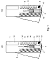
- Fig. 1 a) and 1b) schematically illustrate a device according to the invention with magazine (6) in a longitudinal section.
- the Fig. 1 a) shows a prestressed state of the device
- Fig. 1 b) shows the device at the puncture.
- the device consists of a reusable Handpiece 1 and at least one single-use sensor unit 2, the a storage magazine 6 is moved to the workstation 7.
- the Sensor unit 2 is a disposable article and is sterile in the magazine 6, in a for packed the measurement designed, unmistakable position.
- Handpiece 1 is a pneumatic drive device housed out of a piston 8, by the force of a spring 9 in a cylinder 10th is driven down.
- the drive device is actuated by a Trigger 11, which is pressed on the handle 1 from the outside by a user can be. Furthermore, in the handpiece 1, a measuring unit 12, a Optical fiber 13, an electronic unit 14 for evaluation, a battery 15 and integrated electric motors 16 for setting the function parameters.
- Fig. 1 a) shows the prestressed state, that is, the spring 9 is from Trigger 11 is still held in a compressed position.
- Fig. 1 b) illustrates how after moving the sensor unit 2 from the magazine 6 on the Function point 7, a movable cylinder 17 is moved downward.
- the cylinder 10 could also be made movable. Characterized in that the movable cylinder 17 after is moved down, creates a closed space 18, which through the piston 8, the fixed cylinder 10, the sensor unit 2 and the movable cylinder 17 is enclosed.
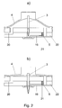
- FIGs 2a) and 2b) are two schematic representations of a sensor unit 2 in cross section.
- Fig. 2a) shows a state of rest by the Sensor unit 2 is not used
- Fig. 2b) shows the time of Puncture.
- the piston 8 is displaced by the spring 9 downwards, whereby the air in the closed space 18 is compressed.
- the pressure generated in this way presses one upper membrane 4 of the sensor unit 2 down, creating a microneedle 3rd also moved down into the human skin.
- Variable adjustable openings in the movable cylinder 17 or in the piston 8 provide sure that the pressure in the closed space 18 decreases and the flexible Membrane 4 of the sensor unit 2 returns to its original shape. Thereby A negative pressure forms under the membrane 4 of the sensor unit 2, through which Body fluid, z. As blood, from the puncture site into a capillary 19 of the Sensor unit 2 is sucked.
- the method for sampling and analysis of body fluids with the Device according to the invention consists of several steps.
- the first step is practiced by the handpiece 1 recorded pneumatic Drive device via the compressed air space 18 pressure on the elastic membrane 4 for piercing the on the elastic membrane. 4 Attached microneedle 3 on the skin surface, and the microneedle 3 penetrates into the skin surface, shown in Fig. 2b).
- the air under the elastic membrane 4th passed through a vent passage 20 to the outside.
- Venting channel 20 a not shown flap valve. Subsequently, the Pressure in the space 18 is reduced to the elastic membrane 4.
- the Sensor unit 2 By the Return of the membrane 4 to the original shape is inside the Sensor unit 2 generates a negative pressure and body fluid from the Penetration actively transported to at least one sensor system 5.
- a filter 21 used to certain components of the To filter out body fluid.
- a physical or chemical Property change of the sensor system 5 causes.
- One by caused change in optical parameters is a transparent Window 22 measured.
- the measuring unit 12 determines from the property changes, here's the change of an optical one Parameters, the concentration value of a component to be determined and displays it on a display 25.
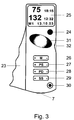
- Fig. 3 is a front view of the device with adjustment buttons 26, 27, 28, 29 and display 25.
- the following functional elements are placed on the handle 1: a movable handle 23, a release button 24, a multifunctional display 25, an m (m emory) 26 key for the storage and retrieval of the measured values and setting parameters, a PS (p enetration s peed) 27 button for setting the infeed rate, a PD (p enetration d epth) 28 button for setting the penetration depth, a key SS ( s uction s trength) 29 for the adjustment of the suction strength and a button 30 for the discharge of the used sensor unit.
- the used sensor unit 2 is dropped by the operation of the handle 23.
- the handle 23 is ergonomically shaped.
- a surface piece 31 are further provided with roughened surface and a recess 32 for a comfortable and non-slip holding.
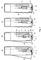
- Fig. 4a shows the initial state of the device with the again usable handle 1 and the trained as a disposable item Sensor units 2, preferably before use in a sterile packaging stored in the magazine 6.
- the movable cylinder 17 and the piston 8 are in their lower position, and one already used Sensor unit 2 has already been ejected. Therefore is located at the Function point 7 no sensor unit 2.
- Fig. 4b) is to light Pressing the handle 23 of the movable cylinder 17 by an arm 33rd moved upward and a sensor unit 2 in the direction of workstation 7.
- a further mechanism is actuated by the handle 23, the from a rack 34, a gear segment 35, a first lever arm 36 and a second lever arm 37 consists.
- the gear segment 35 and the Lever arm 36 are rigidly connected together and have a common fixed axis of rotation at the point of their meeting.
- the translation of the Movement is dimensioned so that when fully depressing the Handle 23 of FIG. 4c), the second lever arm 37, the piston 8 with the Guide rod 38 pushes up to the top point, whereby the spring. 9 is biased and the trigger 11 can hold the drive device, as shown in Fig. 4d).
- the function point 7 Just before the highest position of the piston 8 in FIG. 4c) already reached the sensor unit 2, the function point 7.
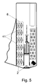
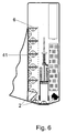
- FIGs. 5 to 7 are schematic representations of a device in Longitudinal section with various alternative arrangements of the sensor units 2 shown in the magazine 6.
- Fig. 5 shows three parallel bands 41 with mounted thereon sensor units 2, in each case six sensor units per band 41.
- the band 41 with the attached thereto Sensor units 2 folded several times in the magazine 6.
- FIG. 7 shows a Solution in which the band 41 with the sensor units 2 mounted thereon for Most along the inner wall of the magazine 6 is located.
- Fig. 1 is a another form of accommodation of the sensor units 2 in the magazine 6 known in which the sensor units 2 are stacked on each other.
- the magazine 6 can after opening a magazine compartment from below into the handle 1 are inserted, which corresponds to those shown in FIGS. 1, 5 and 6 Variants, or by opening the rear cover of the handle 1 are inserted, according to the variant in Fig. 7.
- the handpiece 1 can be formed symmetrically to the plane shown, so that an exchange of the front cover with the adjustment buttons 26, 27, 28, 29 and the display 25 with the back cover is possible. So that could be Device with asymmetrically molded handle 23 for left-handers also lie well in the hand.
Abstract
Description
Gegenstand der Erfindung ist eine Vorrichtung sowie ein entsprechendes Verfahren, mit denen die Probenahme einer Körperflüssigkeit, beispielsweise Blut, sowie die quantitative oder qualitative Analyse darin enthaltener Bestandteile durchgeführt werden kann.The invention relates to a device and a corresponding Methods by which the sampling of a body fluid, for example Blood, as well as the quantitative or qualitative analysis contained therein Components can be performed.
In der klinischen Diagnostik ist die Untersuchung von Körperflüssigkeiten, insbesondere von Blut, eine wichtige Methode, um den Gesundheitszustand eines Patienten zu überprüfen. Die häufigsten Untersuchungen werden dabei im Bereich Homecare mit Kapillarblut vom Patienten selbst durchgeführt. Für solche Anwendungen, vor allem für die Bestimmung des Glucosespiegels im Blut, verwenden die Patienten Einstechhilfen, um die Haut leicht zu verletzen und einen kleinen Blutstropfen zu erhalten. Diese Blutprobe wird dann in der Regel auf einen Teststreifen aufgetragen, der mit Hilfe eines Messgeräts ausgewertet wird. Um diese umständliche Prozedur zu vereinfachen und den Schmerz des Patienten zu minimieren, sind bereits zahlreiche Methoden und Technologien entwickelt worden. Dabei wurde versucht, mehrere Arbeitsschritte mit einem einzigen Gerät durchzuführen und außerdem die zur Untersuchung erforderliche Blutmenge zu reduzieren.In clinical diagnostics, the study of body fluids, especially of blood, an important method of health status to check a patient. The most common examinations will be included in homecare with capillary blood done by the patient himself. For Such applications, especially for the determination of glucose level in the Blood, patients use piercing aids to easily hurt the skin and to get a small drop of blood. This blood sample will then be in the Usually applied to a test strip, using a measuring device is evaluated. To simplify this complicated procedure and the To minimize pain of the patient are already numerous methods and Technologies have been developed. It was tried several steps with a single device and also for examination reduce required amount of blood.
Die Handhabung wird mit Kompaktgeräten verbessert, bei denen die Stechhilfe
und die Messeinheit in einem Gerät integriert sind. Derartige Geräte werden in
der US 6 352 514, EP 1 362 551, EP 1 360 934, EP 1 360 933, WO 03/088834
und WO 02/101359 beschrieben. Die US 6 352 514 und die EP 1 360 933
beschreiben die Verwendung von Lanzetten und Teststreifen in einzelnen
Sensoreinheiten, während aus den anderen Schriften jeweils eine Anordnung
mit zahlreichen Lanzetten und Sensoreinheiten hervorgeht. Handling is improved with compact equipment, in which the lancing device
and the measuring unit are integrated in one device. Such devices are in
US 6,352,514,
Eine Messeinheit mit einem nicht näher spezifizierten Testelement ist aus der
EP 1 287 785 bekannt, eine Messeinheit mit einem elektrischen Sensor wird in
der US 6 607 658 beschrieben, und aus der EP 1 342 448 ist eine auf optischer
Messung beruhende Einheit bekannt.A measuring unit with an unspecified test element is from the
Die Nachteile der bekannten Stechhilfen, Sensorsysteme und integrierten Geräte lassen sich wie folgt zusammenfassen: Es werden relativ große Mengen an Körperflüssigkeit, in der Regel Blut, benötigt, das Stechen ist schmerzhaft, die Herstellungskosten für entsprechende Geräte sind hoch, die Geräte sind groß, schwer und haben einen hohen Energiebedarf, Hygiene und Komfort sind verbesserungsfähig.The disadvantages of the known lancing devices, sensor systems and integrated Devices can be summarized as follows: There are relatively large quantities Body fluid, usually blood, is needed, the stinging is painful, the manufacturing costs for corresponding devices are high, the devices are tall, heavy and have a high energy requirement, hygiene and comfort are improvement.
Die Aufgabe der vorliegenden Erfindung besteht darin, eine Vorrichtung sowie ein entsprechendes Verfahren, mit denen die Probenahme einer Körperflüssigkeit, beispielsweise Blut, sowie die quantitative Analyse darin enthaltener Bestandteile durchgeführt werden kann, so zu verbessern, dass der Komfort für den Benutzer bei geringen Kosten möglichst groß ist.The object of the present invention is to provide a device as well a corresponding procedure by which the sampling of a Body fluid, such as blood, as well as the quantitative analysis therein contained ingredients can be carried out so as to improve the Comfort for the user at low cost is as large as possible.
Die Aufgabe wird erfindungsgemäß gelöst durch eine Vorrichtung nach dem
Anspruch 1 sowie ein entsprechendes Verfahren.The object is achieved by a device according to the
Die Vorrichtung zur Probenahme und Analyse von Körperflüssigkeiten, dabei ist insbesondere an Blut gedacht, umfasst ein Handteil, das eine pneumatische Antriebseinrichtung aufnimmt, und ein Magazin mit mindestens einer Sensoreinheit, die jeweils eine Mikronadel, die fest mit einer elastischen Membran verbunden ist und mindestens ein Sensorsystem enthält. Das Handteil und das Magazin sind vorteilhafterweise lösbar miteinander verbunden. Ein Fördermechanismus schiebt eine erste Sensoreinheit aus dem Magazin auf die Funktionsstelle und spannt die pneumatische Antriebseinrichtung vor, die nach ihrem Auslösen die Probenahme startet. Die mindestens eine Sensoreinheit ist in dem Magazin steril eingepackt, und ein Fördersystem ermöglicht die sequentielle, automatische Einführung der Sensoreinheiten aus dem Magazin auf die Funktionsstelle. Die Antriebseinrichtung steht mit der Sensoreinheit aus dem Magazin, die sich an der Funktionsstelle befindet, auf die Weise in Wechselwirkung, dass die pneumatische Antriebseinrichtung über einen komprimierten Luftraum einen gewissen Druck auf die elastische Membran zum Einstechen der Mikronadel auf eine Hautoberfläche für die Entnahme von Körperflüssigkeit ausübt. Anschließend wird der Druck auf die elastische Membran verringert. Durch das Zurückweichen der Membran in die ursprüngliche Form wird im Inneren der Sensoreinheit ein Unterdruck erzeugt und Körperflüssigkeit aus der Einstichstelle aktiv zu mindestens einem Sensorsystem transportiert. Im Sensorsystem wird durch bestimmte Bestandteile der Körperflüssigkeit eine physikalische oder chemische Eigenschaftsänderung des Sensorsystems bewirkt.The device for sampling and analysis of body fluids, thereby is intended in particular to blood, includes a handpiece, which is a pneumatic Drive unit receives, and a magazine with at least one Sensor unit, each with a microneedle fixed with an elastic Membrane is connected and contains at least one sensor system. The Handpiece and the magazine are advantageously releasable with each other connected. A conveying mechanism pushes a first sensor unit out of the Magazine on the workstation and clamps the pneumatic Drive device that starts sampling after their triggering. The at least one sensor unit is sterile packed in the magazine, and a Conveyor system allows the sequential, automatic introduction of Sensor units from the magazine to the workstation. The Drive device stands with the sensor unit from the magazine, which is on the workstation interacts in the way that the pneumatic drive device via a compressed air space a certain pressure on the elastic membrane for piercing the microneedle on a skin surface for the removal of body fluid. Subsequently, the pressure on the elastic membrane is reduced. By the The membrane will return to its original shape inside the membrane Sensor unit generates a negative pressure and body fluid from the Penetration point actively transported to at least one sensor system. in the Sensor system becomes by certain components of the body fluid one physical or chemical property change of the sensor system causes.
Vorteile der erfindungsgemäßen Vorrichtung sind eine geringe benötigte Menge an Körperflüssigkeit, in der Regel Blut, des Weiteren ein schmerzfreies Stechen. Die Integration von Stecheinheiten und Sensoreinheiten in die Vorrichtung für den einmaligen Gebrauch gewährleistet ein Höchstmaß an Hygiene, die zusätzliche Integration der Messeinheit macht die Anwendung sehr komfortabel und einfach. Mit der Verwendung eines Magazins werden darüber hinaus weitere Nachteile überwunden: Die Anzahl der manuellen Bedienschritte bei der Probenahme und Analyse wird reduziert, und durch die vorgegebene Anordnung der Sensoreinheiten im Magazin wird ein verwechslungsfreier Einsatz der Sensoreinheiten gewährleistet. Gewicht und Energieverbrauch der gesamten Vorrichtung sind darüber hinaus gering.Advantages of the device according to the invention are a small amount required on body fluid, usually blood, furthermore a painless Sting. The integration of lancing units and sensor units in the Single use device ensures the highest possible Hygiene, the additional integration of the measuring unit makes the application very comfortable and easy. With the use of a magazine will be In addition, other disadvantages overcome: the number of manual Sampling and analysis operations are reduced, and by the predetermined arrangement of the sensor units in the magazine is a guaranteed use of sensor units without confusion. Weight and Energy consumption of the entire device are also low.
Bevorzugte Ausführungsformen der Erfindung sind Gegenstand der Unteransprüche.Preferred embodiments of the invention are the subject of Dependent claims.
Die Antriebseinrichtung zum Einstechen der Mikronadel und anschließenden Ansaugen von Körperflüssigkeit beruht auf einem einfachen mechanischen Prinzip, ist leicht zu handhaben und wenig störanfällig. Mit einer entsprechenden Bemessung des Innenraums der Sensoreinheit kann die erforderliche Probemenge an Körperflüssigkeit optimal reduziert werden. Die Verwendung einer Mikronadel mit Unterstützung einer Sogwirkung zur Förderung des Blutaustritts hält die Schmerzen dabei gering. Besonders günstig ist die lösbare Verbindung von Handteil und Magazin, denn dadurch ist es möglich, die im Magazin befindlichen Sensoreinheiten oder auch das Magazin mit den Sensoreinheiten als sterilen Wegwerfartikel auszuführen. Eine kostengünstige Möglichkeit besteht beispielsweise in der Fertigung als Spritzgussteil.The drive device for piercing the microneedle and subsequent Aspiration of body fluid is based on a simple mechanical Principle, is easy to handle and less susceptible to interference. With a appropriate dimensioning of the interior of the sensor unit, the required sample amount of body fluid can be optimally reduced. The Using a microneedle with the help of a suction effect for Promoting blood leakage keeps the pain low. Especially low is the detachable connection of the handle and magazine, because this is It is possible, the sensor units located in the magazine or the Carry out magazine with the sensor units as a sterile disposable item. A cost-effective possibility exists for example in the production as Injection molded part.
Eine bevorzugte Ausgestaltung der Vorrichtung besteht darin, dass das Handteil eine Messeinheit mit Anzeige zur Bestimmung der im Sensorsystem durch Einwirken bestimmter Bestandteile der Körperflüssigkeit hervorgerufenen physikalischen oder chemischen Eigenschaftsänderungen enthält. Die Messeinheit bestimmt aus diesen Eigenschaftsänderungen den Konzentrationswert eines zu bestimmenden Bestandteils der Körperflüssigkeit, der daraufhin auf der Anzeige angezeigt wird. Auf diese Weise ist es möglich, in einem einzigen Prozess eine Probenahme durchzuführen, den gewünschten Analysewert zu bestimmen und für den Benutzer unmittelbar anzuzeigen.A preferred embodiment of the device is that the Handpiece a measuring unit with display for determining the in the sensor system caused by the action of certain components of the body fluid contains physical or chemical property changes. The Measuring unit determines from these property changes the Concentration value of a constituent of the body fluid to be determined, which will then be displayed on the screen. In this way it is possible in a single process to perform a sampling, the desired To determine the analysis value and immediately display it for the user.
Ebenso ist die Speicherung von Messwerten möglich. Der Anwender kann die vorher abgespeicherten Messwerte durch einen Tastendruck abrufen. In einer speziellen Ausführungsform kann das Ergebnis auch per Transponder oder ähnlichem an ein zweites Gerät weitergegeben werden. Dieses zweite Gerät kann zum Beispiel eine automatische Spritze oder eine Pumpe zur Verabreichung entsprechender Therapeutika wie Insulin sein. Es kann sich hierbei auch um ein Anzeigegerät, zum Beispiel ein Mobiltelefon, eine Armbanduhr, einen PC oder PDA (Personal Digital Assistant) handeln.Likewise, the storage of measured values is possible. The user can retrieve the previously stored measured values by pressing a button. In a special embodiment, the result can also be transmitted by transponder or the like to a second device. This second device may be, for example, an automatic syringe or pump for administration of appropriate therapeutics such as insulin. It may be, this includes a display device such as a mobile phone, a wrist watch, a PC or PDA (P ersonal D igital A ssistant).
Da eine Analyse von Körperflüssigkeiten kostengünstig, zuverlässig und schnell erfolgen soll, sind optische Messverfahren für das Sensorsystem, insbesondere fluoreszenzspektroskopische Messverfahren, von besonderem Vorteil. Bei der Fluoreszenzmessung kann eine minimale Fläche am Sensorsystem verwendet werden, wodurch die Produktion der Sensoreinheiten kostengünstig wird. In einer bevorzugten Ausführung wird als Nachweismethode die FRET-Methode (Fluorescence Resonance Energy Transfer) verwendet.Since an analysis of body fluids should be cost-effective, reliable and fast, optical measurement methods for the sensor system, in particular fluorescence spectroscopic measurement methods, are of particular advantage. In fluorescence measurement, a minimal area on the sensor system can be used, making the production of the sensor units inexpensive. In a preferred embodiment, the FRET method is called the detection method (F luorescence R esonance E nergy T ransfer) was used.
Die lösbare Verbindung zwischen dem Handteil und dem Magazin ist in vorteilhafter Weise als schnell einrastende Verbindung ausgeführt. Das kann beispielsweise eine Steck-, Klemm-, Schnapp- oder Klebeverbindung sein. Wichtig ist dabei in jedem Fall, dass das Lösen und Herstellen der Verbindung schnell und einfach erfolgt und ein Verbinden von Handteil und Magazin zu einem stabilen Gerät führt.The detachable connection between the handle and the magazine is in advantageously designed as a fast snap connection. That can For example, be a plug-in, clamped, snap or adhesive connection. It is important in any case that the loosening and making the connection done quickly and easily and connecting the handset and magazine too a stable device leads.
Für die bessere Hygiene und bequeme Handhabung ist vorgesehen, dass mehrere Sensoreinheiten in einem Magazin eingepackt sind und in einem Arbeitsschritt in das Gerät eingesetzt werden. Aus dem Magazin wird dann für jede Untersuchung eine Sensoreinheit durch die Betätigung eines Fördermechanismus auf die Funktionsstelle geschoben und für den Messvorgang vorbereitet. Diese Automatisierung durch einen Fördermechanismus ist deshalb wichtig, da sich das Sensorsystem der Sensoreinheit in präziser Lage gegenüber der optischen Messeinheit des Handteils befinden soll.For the better hygiene and comfortable handling it is provided that several sensor units are packed in a magazine and in one Step into the device are used. From the magazine will then for each examination a sensor unit by the operation of a Moving mechanism pushed to the workstation and for the Measuring process prepared. This automation by a Conveyor mechanism is important because the sensor system of the Sensor unit in precise position opposite the optical measuring unit of the Handpiece should be located.
In einer weiteren Ausführungsform ist vorgesehen, dass das Handteil ein Einstellglied für eine variable Vorgabe der Einstichtiefe der Mikronadel aufweist. Das macht sich besonders dann vorteilhaft bemerkbar, wenn die Einstichtiefe individuell an die Einstichstelle auf der Haut angepasst werden soil. So hängt es stark vom Ort des Einstichs ab, ob die Hautoberfläche dort dicker oder dünner ist und ob die Blutgefäße tiefer oder weniger tief liegen.In a further embodiment it is provided that the hand part a Setting member for a variable specification of the penetration depth of the microneedle has. This is particularly advantageous when the penetration depth should be adjusted individually to the injection site on the skin. That's how it depends strongly depending on the location of the puncture, whether the skin surface is thicker or thinner and whether the blood vessels are deeper or less deep.
Die Einstichtiefe kann elektrisch, wie im Beispiel durch Anwendung eines Elektromotors, oder durch einen mechanischen Regler festgelegt werden. Die elektrisch gesteuerte Einstellung wird mit Hilfe einer ±-Taste durchgeführt, wobei der eingestellte Wert auf einer Multifunktions-Anzeige abgelesen wird. The penetration depth can be electrical, as in the example by using a Electric motor, or be set by a mechanical regulator. The electrically controlled adjustment is carried out with the aid of a ± key, where the set value is read on a multifunction display.
Darüber hinaus ist es möglich, dass ein zweites Einstellglied am Handteil für eine variable Vorgabe der Einstechgeschwindigkeit angebracht ist. Auf diese Weise ist eine individuelle Anpassung möglich, um den Schmerz möglichst gering zu halten. Die Einstechgeschwindigkeit kann ebenfalls elektrisch mit Hilfe einer ±-Taste eingestellt und auf einer Multifunktions-Anzeige abgelesen werden.In addition, it is possible that a second adjusting member on the handle for a variable specification of the piercing speed is appropriate. To this Way, individual adaptation is possible to minimize the pain to keep low. The piercing speed can also be electrically with Help with a ± -key set and read on a multi-function display become.
Ebenso besteht die Möglichkeit für eine elektronische oder mechanische Einstellung der Ansauggeschwindigkeit von Körperflüssigkeit mittels eines dritten Einstellglieds.It is also possible for an electronic or mechanical Adjustment of the rate of aspiration of body fluid by means of a third setting member.
Der Fördermechanismus zum Wechsel der Sensoreinheit und Vorspannen der Stecheinrichtung kann gleichzeitig zur elektrischen Energieerzeugung benutzt werden. Bei Betätigung des Handgriffes wird durch die Bewegung des Fördermechanismus ein kleiner Dynamo in Rotation versetzt. Die von diesem Dynamo erzeugte elektrische Energie kann zum Beispiel in einer Batterie gespeichert werden. Die so gewonnene Energie kann für die Durchführung der Messung bzw. Anzeige des Messergebnisses auf der Anzeige verwendet werden. Die Energie der Batterie dient vor Allem zur Speicherung und zum Abruf der Messdaten sowie zur Einstellung und Abspeicherung der Einstechparameter.The conveying mechanism for changing the sensor unit and preloading the Lancing device can be used simultaneously for electrical power generation become. When the handle is operated by the movement of the Conveying mechanism a small dynamo rotated. The one of this Dynamo generated electrical energy can, for example, in a battery get saved. The energy thus gained can be used to carry out the Measurement or display of the measurement result used on the display become. The energy of the battery is mainly used for storage and Retrieval of the measured data and for setting and saving the Piercing parameters.
Die Erfindung wird anhand der folgenden Zeichnungen beispielhaft erläutert.The invention will be explained by way of example with reference to the following drawings.
- Fig. 1 a), b)Fig. 1 a), b)
- zwei schematische Darstellungen einer erfindungsgemäßen Vorrichtung mit Magazin in einem Längsschnitt, in Fig. 1a) im vorgespannten Zustand und in Fig. 1b) beim Einstich;two schematic representations of an inventive Device with magazine in a longitudinal section, in Fig. 1a) in prestressed state and in FIG. 1b) during puncture;
- Fig. 2a), b)Fig. 2a), b)
- zwei schematische Darstellungen einer Sensoreinheit im Querschnitt, in Fig. 2a) im Ruhezustand und in Fig. 2b) beim Einstich; two schematic representations of a sensor unit in Cross-section, in Fig. 2a) at rest and in Fig. 2b) at Puncture;
- Fig. 3Fig. 3
- eine Ansicht des Gerätes von vorne mit Einstelltasten und Anzeige;a view of the device from the front with adjustment buttons and Display;
- Fig. 4a) -d)Fig. 4a) -d)
- vier schematische Darstellungen einer erfindungsgemäßen Vorrichtung im Längsschnitt in zeitlicher Abfolge, die das Funktionsprinzip der Vorrichtung veranschaulichen;four schematic representations of an inventive Device in longitudinal section in chronological order, the Illustrate the operating principle of the device;
- Fig. 5Fig. 5
- eine schematische Darstellung einer erfindungsgemäßen Vorrichtung im Längsschnitt mit einer alternativen Anordnung der Sensoreinheiten im Magazin;a schematic representation of an inventive Device in longitudinal section with an alternative arrangement the sensor units in the magazine;
- Fig. 6Fig. 6
- eine schematische Darstellung einer erfindungsgemäßen Vorrichtung im Längsschnitt mit einer weiteren Anordnung der Sensoreinheiten im Magazin;a schematic representation of an inventive Device in longitudinal section with a further arrangement of Sensor units in the magazine;
- Fig. 7Fig. 7
- eine schematische Darstellung einer erfindungsgemäßen Vorrichtung im Längsschnitt mit einer alternativen Anordnung der Sensoreinheiten im Magazin.a schematic representation of an inventive Device in longitudinal section with an alternative arrangement the sensor units in the magazine.
Die Fig. 1 a) und 1b) stellen schematisch eine erfindungsgemäße Vorrichtung
mit Magazin (6) in einem Längsschnitt dar. Die Fig. 1 a) zeigt einen
vorgespannten Zustand der Vorrichtung, und die Fig. 1 b) zeigt die Vorrichtung
beim Einstich. Die Vorrichtung besteht aus einem wieder verwendbaren
Handteil 1 und mindestens einer einmal verwendbaren Sensoreinheit 2, die aus
einem Vorratsmagazin 6 auf die Funktionsstelle 7 verschoben wird. Die
Sensoreinheit 2 ist ein Wegwerfartikel und wird im Magazin 6 steril, in einer für
die Messung ausgelegten, unverwechselbaren Position eingepackt. In dem
Handteil 1 ist eine pneumatische Antriebseinrichtung untergebracht, die aus
einem Kolben 8 besteht, der durch die Kraft einer Feder 9 in einem Zylinder 10
nach unten getrieben wird. Die Antriebseinrichtung wird betätigt durch einen
Auslöser 11, der am Handteil 1 von außen durch einen Benutzer eingedrückt
werden kann. Des Weiteren sind im Handteil 1 eine Messeinheit 12, ein
Lichtleiter 13, eine elektronische Einheit 14 für die Auswertung, eine Batterie 15
sowie Elektromotoren 16 für die Einstellung der Funktionsparameter integriert.
Die Fig. 1 a) zeigt den vorgespannten Zustand, das heißt, die Feder 9 wird vom
Auslöser 11 noch in gestauchter Position gehalten. Die Fig. 1 b) stellt dar, wie
nach Verschieben der Sensoreinheit 2 aus dem Magazin 6 auf die
Funktionsstelle 7 ein beweglicher Zylinder 17 nach unten verschoben wird. Hier
nicht abgebildet, aber als Alternative denkbar, könnte der Zylinder 10 ebenfalls
beweglich gestaltet werden. Dadurch, dass der bewegliche Zylinder 17 nach
unten verschoben wird, entsteht ein geschlossener Raum 18, welcher durch
den Kolben 8, den fix angeordneten Zylinder 10, die Sensoreinheit 2 und den
beweglichen Zylinder 17 umschlossen wird.Fig. 1 a) and 1b) schematically illustrate a device according to the invention
with magazine (6) in a longitudinal section. The Fig. 1 a) shows a
prestressed state of the device, and Fig. 1 b) shows the device
at the puncture. The device consists of a
Die Fig. 2a) und 2b) sind zwei schematische Darstellungen einer Sensoreinheit
2 im Querschnitt. Die Fig. 2a) zeigt einen Ruhezustand, indem die
Sensoreinheit 2 nicht benutzt wird, und die Fig. 2b) zeigt den Zeitpunkt des
Einstichs. Beim Auslösen des Einstechvorganges durch den Auslöser 11 wird
der Kolben 8 durch die Feder 9 nach unten verschoben, wodurch die Luft im
geschlossenen Raum 18 komprimiert wird. Der so erzeugte Druck presst eine
obere Membran 4 der Sensoreinheit 2 nach unten, wodurch eine Mikronadel 3
ebenfalls nach unten in die menschliche Haut verschoben wird. Variabel
einstellbare Öffnungen im beweglichen Zylinder 17 oder im Kolben 8 stellen
sicher, dass der Druck im geschlossenen Raum 18 nachlässt und die flexible
Membran 4 der Sensoreinheit 2 in die ursprüngliche Form zurückkehrt. Dadurch
bildet sich ein Unterdruck unter der Membran 4 der Sensoreinheit 2, durch den
Körperflüssigkeit, z. B. Blut, aus der Einstichstelle in eine Kapillare 19 der
Sensoreinheit 2 ansaugt wird.Figures 2a) and 2b) are two schematic representations of a
Das Verfahren zur Probenahme und Analyse von Körperflüssigkeiten mit der
erfindungsgemäßen Vorrichtung besteht aus mehreren Schritten. In einem
ersten Schritt übt die vom Handteil 1 aufgenommene pneumatische
Antriebseinrichtung über den komprimierten Luftraum 18 Druck auf die
elastische Membran 4 zum Einstechen der an der elastischen Membran 4
befestigten Mikronadel 3 auf die Hautoberfläche aus, und die Mikronadel 3
dringt in die Hautoberfläche ein, dargestellt in Fig. 2b). Bei der Druckeinwirkung
auf die elastische Membran 4 wird die Luft unter der elastischen Membran 4
durch einen Entlüftungskanal 20 nach außen geleitet. Um die
Strömungsrichtung der Luft nach außen zu sichern, befindet sich im
Entlüftungskanal 20 ein nicht abgebildetes Klappventil. Anschließend wird der
Druck im Raum 18 auf die elastische Membran 4 verringert. Durch das
Zurückweichen der Membran 4 in die ursprüngliche Form wird im Inneren der
Sensoreinheit 2 ein Unterdruck erzeugt und Körperflüssigkeit aus der
Einstichstelle aktiv zu mindestens einem Sensorsystem 5 transportiert. Vor dem
Sensorsystem 5 ist ein Filter 21 eingesetzt, um bestimmte Komponenten der
Körperflüssigkeit auszufiltern. Im Sensorsystem 5 wird durch bestimmte
Bestandteile der Körperflüssigkeit eine physikalische oder chemische
Eigenschaftsänderung des Sensorsystems 5 bewirkt. Eine dadurch
hervorgerufene Änderung optischer Parameter wird durch ein transparentes
Fenster 22 gemessen. In einem nächsten Schritt bestimmt die Messeinheit 12
aus den Eigenschaftsänderungen, das ist hier die Änderung eines optischen
Parameters, den Konzentrationswert eines zu bestimmenden Bestandteils und
zeigt ihn auf einer Anzeige 25 an.The method for sampling and analysis of body fluids with the
Device according to the invention consists of several steps. In one
The first step is practiced by the
Die Fig. 3 ist eine Ansicht des Gerätes von vorne mit Einstelltasten 26, 27, 28,
29 und Anzeige 25. Zur Bedienung des Gerätes werden die folgenden
Funktionselemente auf dem Handteil 1 angeordnet: ein beweglicher Handgriff
23, ein Auslöseknopf 24, ein multifunktionelle Anzeige 25, eine Taste M
(memory) 26 für die Abspeicherung und den Abruf der Messwerte und
Einstellparameter, eine Taste PS (penetration speed) 27 für die Einstellung der
Einstechgeschwindigkeit, eine Taste PD (penetration depth) 28 für die
Einstellung der Einstichtiefe, eine Taste SS (suction strength) 29 für die
Einstellung der Saugstärke und ein Knopf 30 für den Abwurf der gebrauchten
Sensoreinheit. Alternativ wird die gebrauchte Sensoreinheit 2 durch die
Betätigung des Handgriffes 23 abgeworfen. Der Handgriff 23 ist ergonomisch
geformt. Hierfür sind weiterhin ein Flächenstück 31 mit aufgerauhter Oberfläche
und eine Vertiefung 32 für ein bequemes und rutschfestes Halten vorgesehen. Fig. 3 is a front view of the device with
Die Fig. 4a) bis d) sind vier schematische Darstellungen einer erfindungsgemäßen Vorrichtung im Längsschnitt in zeitlicher Abfolge, die das Funktionsprinzip der Vorrichtung veranschaulichen. Durch das Andrücken des Handgriffes 23 werden vier verschiedene Bewegungen in Gang gesetzt:
- 1.
Eine Sensoreinheit 2 wird ausdem Magazin 6 auf dieFunktionsstelle 7 verschoben,- 2.
- der bewegliche Zylinder 17 wird nach oben verschoben,
- 3.
- die
Feder 9 der pneumatischen Antriebseinrichtung wird vorgespannt und - 4.
- ein nicht abgebildeter Dynamo wird in Rotation versetzt.
- 1.
- A
sensor unit 2 is moved from themagazine 6 to theworkstation 7, - Second
- the
movable cylinder 17 is moved upwards, - Third
- the
spring 9 of the pneumatic drive device is biased and - 4th
- an unrepresented dynamo is rotated.
Die Fig. 4a) zeigt den Ausgangszustand der Vorrichtung mit dem wieder
verwendbaren Handteil 1 und den als Wegwerfartikel ausgebildeten
Sensoreinheiten 2, die vor Gebrauch vorzugsweise in einer sterilen Verpackung
im Magazin 6 aufbewahrt werden. Der bewegliche Zylinder 17 und der Kolben 8
befinden sich in ihrer unteren Position, und eine bereits gebrauchte
Sensoreinheit 2 wurde schon vorher ausgeworfen. Daher befindet sich an der
Funktionsstelle 7 keine Sensoreinheit 2. In der Fig. 4b) wird nach leichtem
Andrücken des Handgriffs 23 der bewegliche Zylinder 17 durch einen Arm 33
nach oben und eine Sensoreinheit 2 in Richtung Funktionsstelle 7 verschoben.
Gleichzeitig wird durch den Handgriff 23 ein weiterer Mechanismus betätigt, der
aus einer Zahnstange 34, einem Zahnradsegment 35, einem ersten Hebelarm
36 und einem zweiten Hebelarm 37 besteht. Das Zahnradsegment 35 und der
Hebelarm 36 sind starr miteinander verbunden und haben eine gemeinsame
feste Drehachse am Punkt ihres Aufeinandertreffens. Die Übersetzung der
Bewegung ist so dimensioniert, dass beim vollständigen Eindrücken des
Handgriffs 23 gemäß Fig. 4c) der zweite Hebelarm 37 den Kolben 8 mit der
Führungsstange 38 bis zum obersten Punkt hochschiebt, wodurch die Feder 9
vorgespannt wird und der Auslöser 11 die Antriebseinrichtung festhalten kann,
wie in Fig. 4d) dargestellt. Kurz vor der höchsten Position des Kolbens 8 in Fig.
4c) erreicht schon die Sensoreinheit 2 die Funktionsstelle 7. Wenn der Kolben 8
in Fig. 4d) seine oberste Position erreicht hat, wird seine Halterung 39 durch
den Auslöser 11 festgehalten und der Hebelarm 33 des beweglichen Zylinders
17 ausgeklemmt, wodurch der bewegliche Zylinder 17 durch eine nicht
abgebildete Feder nach unten verschoben wird. Dadurch wird der Raum 18
unter dem Zylinder 8 geschlossen. Damit ist das Gerät für die Messung
vorbereitet. Die Zahnstange 34 versetzt in den Fig. 4c) und 4d) ein kleines
Zahnrad 40 in Rotation. Das Zahnrad 40 wird mit einem nicht abgebildeten
Dynamo verbunden, der durch die Rotation Strom erzeugt und eine
Energieversorgungseinheit, zum Beispiel eine Batterie, auflädt. Die
Energieversorgungseinheit kann die Energie für einen vollständigen Messablauf
erzeugen.Fig. 4a) shows the initial state of the device with the again
In den Fig. 5 bis 7 werden schematische Darstellungen einer Vorrichtung im
Längsschnitt mit verschiedenen alternativen Anordnungen der Sensoreinheiten
2 im Magazin 6 dargestellt. Fig. 5 zeigt drei parallel liegende Bänder 41 mit
darauf befestigten Sensoreinheiten 2, und zwar jeweils sechs Sensoreinheiten
pro Band 41. In Fig. 6 liegt das Band 41 mit den darauf befestigten
Sensoreinheiten 2 mehrfach gefaltet im Magazin 6. Die Fig. 7 zeigt eine
Lösung, bei der das Band 41 mit den darauf befestigten Sensoreinheiten 2 zum
Großteil entlang der Innenwand des Magazins 6 liegt. Aus der Fig. 1 ist eine
weitere Form der Unterbringung der Sensoreinheiten 2 im Magazin 6 bekannt,
bei der die Sensoreinheiten 2 aufeinander gestapelt sind. Das Magazin 6 kann
nach der Öffnung eines Magazinfachs von unten in das Handteil 1
eingeschoben werden, das entspricht den in den Fig. 1, 5 und 6 abgebildeten
Varianten, oder durch Öffnung der hinteren Abdeckung des Handteils 1
eingelegt werden, entsprechend der Variante in Fig. 7.In Figs. 5 to 7 are schematic representations of a device in
Longitudinal section with various alternative arrangements of the
Das Handteil 1 kann zur dargestellten Ebene symmetrisch ausgeformt werden,
so dass ein Umtausch des Frontdeckels mit den Einstelltasten 26, 27, 28, 29
und der Anzeige 25 mit der hinteren Abdeckung möglich ist. So könnte das
Gerät mit asymmetrisch angeformtem Handgriff 23 für Linkshänder ebenfalls
gut in der Hand liegen.The
Claims (13)
Priority Applications (1)
| Application Number | Priority Date | Filing Date | Title |
|---|---|---|---|
| EP04010983A EP1529488A1 (en) | 2003-06-27 | 2004-05-08 | Device and method for sampling and analysing body fluids |
Applications Claiming Priority (5)
| Application Number | Priority Date | Filing Date | Title |
|---|---|---|---|
| EP03014772 | 2003-06-27 | ||
| EP03014772A EP1522260A1 (en) | 2003-06-27 | 2003-06-27 | Device for blood sampling and simultaneous quantitative determination of blood analytes |
| EP04002436 | 2004-02-04 | ||
| EP04002436A EP1621132B1 (en) | 2003-06-27 | 2004-02-04 | Device and method for sampling and analysing body fluids |
| EP04010983A EP1529488A1 (en) | 2003-06-27 | 2004-05-08 | Device and method for sampling and analysing body fluids |
Publications (1)
| Publication Number | Publication Date |
|---|---|
| EP1529488A1 true EP1529488A1 (en) | 2005-05-11 |
Family
ID=34437549
Family Applications (1)
| Application Number | Title | Priority Date | Filing Date |
|---|---|---|---|
| EP04010983A Ceased EP1529488A1 (en) | 2003-06-27 | 2004-05-08 | Device and method for sampling and analysing body fluids |
Country Status (1)
| Country | Link |
|---|---|
| EP (1) | EP1529488A1 (en) |
Cited By (4)
| Publication number | Priority date | Publication date | Assignee | Title |
|---|---|---|---|---|
| EP1726951A1 (en) * | 2005-05-24 | 2006-11-29 | F. Hoffman-la Roche AG | Cartridge for storing test elements |
| EP1726950A1 (en) * | 2005-05-24 | 2006-11-29 | F. Hoffmann-La Roche Ag | Cartridge for storing test elements |
| GB2479984A (en) * | 2010-04-27 | 2011-11-02 | Maria Smith | Foetal blood sampling probe |
| WO2014174096A1 (en) * | 2013-04-26 | 2014-10-30 | 4A Medicom Gmbh | Individually packaged disposable blood testing unit |
Citations (12)
| Publication number | Priority date | Publication date | Assignee | Title |
|---|---|---|---|---|
| DE2803345B1 (en) * | 1978-01-26 | 1979-06-13 | Emil Eisinger | Blood sampling device |
| US5505212A (en) * | 1991-06-21 | 1996-04-09 | Novo Nordisk A/S | Blood sampler |
| US6352514B1 (en) | 1996-05-17 | 2002-03-05 | Amira Medical | Methods and apparatus for sampling and analyzing body fluid |
| WO2002100251A2 (en) * | 2001-06-12 | 2002-12-19 | Pelikan Technologies, Inc. | Self optimizing lancing device with adaptation means to temporal variations in cutaneous properties |
| WO2002101359A2 (en) | 2001-06-12 | 2002-12-19 | Pelikan Technologies, Inc. | Integrated blood sampling analysis system with multi-use sampling module |
| WO2002100252A2 (en) * | 2001-06-12 | 2002-12-19 | Pelikan Technologies, Inc. | Blood sampling apparatus and method |
| EP1287785A1 (en) | 2001-08-29 | 2003-03-05 | Boehringer Mannheim Gmbh | Analyzing means with lancet and test element |
| US6607658B1 (en) | 1997-02-06 | 2003-08-19 | Therasense, Inc. | Integrated lancing and measurement device and analyte measuring methods |
| WO2003088834A1 (en) | 2002-04-19 | 2003-10-30 | Pelikan Technologies, Inc. | Method and apparatus for a multi-use body fluid sampling device |
| EP1360934A1 (en) | 2002-05-09 | 2003-11-12 | Lifescan, Inc. | Devices and methods for accessing and analyzing physiological fluid |
| EP1360933A1 (en) | 2002-05-09 | 2003-11-12 | Lifescan, Inc. | Physiological sample collection devices and methods of using the same |
| EP1362551A1 (en) | 2002-05-09 | 2003-11-19 | Lifescan, Inc. | Minimal procedure analyte test system |
-
2004
- 2004-05-08 EP EP04010983A patent/EP1529488A1/en not_active Ceased
Patent Citations (12)
| Publication number | Priority date | Publication date | Assignee | Title |
|---|---|---|---|---|
| DE2803345B1 (en) * | 1978-01-26 | 1979-06-13 | Emil Eisinger | Blood sampling device |
| US5505212A (en) * | 1991-06-21 | 1996-04-09 | Novo Nordisk A/S | Blood sampler |
| US6352514B1 (en) | 1996-05-17 | 2002-03-05 | Amira Medical | Methods and apparatus for sampling and analyzing body fluid |
| US6607658B1 (en) | 1997-02-06 | 2003-08-19 | Therasense, Inc. | Integrated lancing and measurement device and analyte measuring methods |
| WO2002100251A2 (en) * | 2001-06-12 | 2002-12-19 | Pelikan Technologies, Inc. | Self optimizing lancing device with adaptation means to temporal variations in cutaneous properties |
| WO2002101359A2 (en) | 2001-06-12 | 2002-12-19 | Pelikan Technologies, Inc. | Integrated blood sampling analysis system with multi-use sampling module |
| WO2002100252A2 (en) * | 2001-06-12 | 2002-12-19 | Pelikan Technologies, Inc. | Blood sampling apparatus and method |
| EP1287785A1 (en) | 2001-08-29 | 2003-03-05 | Boehringer Mannheim Gmbh | Analyzing means with lancet and test element |
| WO2003088834A1 (en) | 2002-04-19 | 2003-10-30 | Pelikan Technologies, Inc. | Method and apparatus for a multi-use body fluid sampling device |
| EP1360934A1 (en) | 2002-05-09 | 2003-11-12 | Lifescan, Inc. | Devices and methods for accessing and analyzing physiological fluid |
| EP1360933A1 (en) | 2002-05-09 | 2003-11-12 | Lifescan, Inc. | Physiological sample collection devices and methods of using the same |
| EP1362551A1 (en) | 2002-05-09 | 2003-11-19 | Lifescan, Inc. | Minimal procedure analyte test system |
Cited By (7)
| Publication number | Priority date | Publication date | Assignee | Title |
|---|---|---|---|---|
| EP1726951A1 (en) * | 2005-05-24 | 2006-11-29 | F. Hoffman-la Roche AG | Cartridge for storing test elements |
| EP1726950A1 (en) * | 2005-05-24 | 2006-11-29 | F. Hoffmann-La Roche Ag | Cartridge for storing test elements |
| US7566419B2 (en) | 2005-05-24 | 2009-07-28 | Roche Diagnostics Operations, Inc. | Magazine for holding test elements |
| GB2479984A (en) * | 2010-04-27 | 2011-11-02 | Maria Smith | Foetal blood sampling probe |
| GB2479984B (en) * | 2010-04-27 | 2016-12-21 | Smith Maria | Foetal blood sampling probe |
| WO2014174096A1 (en) * | 2013-04-26 | 2014-10-30 | 4A Medicom Gmbh | Individually packaged disposable blood testing unit |
| AT514301A1 (en) * | 2013-04-26 | 2014-11-15 | 4A Medicom Gmbh | Single-use disposable blood test unit |
Similar Documents
| Publication | Publication Date | Title |
|---|---|---|
| EP1621132B1 (en) | Device and method for sampling and analysing body fluids | |
| EP1190674B1 (en) | Lancet devices | |
| EP1643909B1 (en) | Analysis apparatus for body fluids | |
| EP1287785B1 (en) | Analyzing means with lancet and test element | |
| DE60317997T2 (en) | lancet | |
| DE19781097B4 (en) | Blood and interstitial fluid sampling device for analysis=processing - uses lancing needle to pierce skin at rapid rate while ultrasonically kneading area to stimulate blood flow and pumping off sample | |
| EP1289422B1 (en) | System for removing body fluid | |
| DE60221347T3 (en) | IN-SITU ADAPTER FOR AN ANALYTE TEST UNIT | |
| DE19861320B4 (en) | Procedure for blood sampling and analysis | |
| EP2129289B1 (en) | Analytical system for determining an analyte in a body fluid and disposable integrated sample collection and analytical element | |
| EP1825257B1 (en) | Diagnostic system for determining substance concentrations in liquid samples | |
| EP1921993B1 (en) | Assembly for receiving body fluids | |
| EP2190352B1 (en) | Combination drive for a sample extraction system for obtaining a liquid sample | |
| EP1743577A1 (en) | Hand-held apparatus for the analysis of bodily fluids | |
| DE10361560A1 (en) | Carrier with a plurality of lancing elements, lancing device and blood analyzer | |
| WO2008068215A2 (en) | Device and method for analyzing body fluids | |
| EP2314206B1 (en) | Piercing system for removal of a bodily fluid | |
| EP2461749B1 (en) | Control device for a medical device | |
| EP2311374A1 (en) | Apparatus for retrieving and analysing blood; coupling mechanism for lancets | |
| WO2007065844A1 (en) | Reusable piercing aid and method for carrying out a piercing movement by means of a reusable piercing aid | |
| EP1529488A1 (en) | Device and method for sampling and analysing body fluids | |
| EP2382921A1 (en) | Lancing device with automatic disengagement | |
| DE69737553T2 (en) | Apparatus for sampling body fluid | |
| DE19758804B4 (en) | Blood and interstitial fluid sampling device for analysis=processing - uses lancing needle to pierce skin at rapid rate while ultrasonically kneading area to stimulate blood flow and pumping off sample |
Legal Events
| Date | Code | Title | Description |
|---|---|---|---|
| PUAI | Public reference made under article 153(3) epc to a published international application that has entered the european phase |
Free format text: ORIGINAL CODE: 0009012 |
|
| AK | Designated contracting states |
Kind code of ref document: A1 Designated state(s): AT BE BG CH CY CZ DE DK EE ES FI FR GB GR HU IE IT LI LU MC NL PL PT RO SE SI SK TR |
|
| AX | Request for extension of the european patent |
Extension state: AL HR LT LV MK |
|
| 17P | Request for examination filed |
Effective date: 20051111 |
|
| AKX | Designation fees paid |
Designated state(s): AT BE BG CH CY CZ DE DK EE ES FI FR GB GR HU IE IT LI LU MC NL PL PT RO SE SI SK TR |
|
| APBN | Date of receipt of notice of appeal recorded |
Free format text: ORIGINAL CODE: EPIDOSNNOA2E |
|
| RAP1 | Party data changed (applicant data changed or rights of an application transferred) |
Owner name: EHRFELD MIKROTECHNIK AG |
|
| RAP1 | Party data changed (applicant data changed or rights of an application transferred) |
Owner name: EHRFELD MIKROTECHNIK AG IN INSOLVENZ |
|
| APBR | Date of receipt of statement of grounds of appeal recorded |
Free format text: ORIGINAL CODE: EPIDOSNNOA3E |
|
| APAF | Appeal reference modified |
Free format text: ORIGINAL CODE: EPIDOSCREFNE |
|
| APBT | Appeal procedure closed |
Free format text: ORIGINAL CODE: EPIDOSNNOA9E |
|
| STAA | Information on the status of an ep patent application or granted ep patent |
Free format text: STATUS: THE APPLICATION HAS BEEN REFUSED |
|
| 18R | Application refused |
Effective date: 20081129 |