EP1529624A1 - Device for welding thermoplastic pipe elements - Google Patents
Device for welding thermoplastic pipe elements Download PDFInfo
- Publication number
- EP1529624A1 EP1529624A1 EP03025628A EP03025628A EP1529624A1 EP 1529624 A1 EP1529624 A1 EP 1529624A1 EP 03025628 A EP03025628 A EP 03025628A EP 03025628 A EP03025628 A EP 03025628A EP 1529624 A1 EP1529624 A1 EP 1529624A1
- Authority
- EP
- European Patent Office
- Prior art keywords
- pipe
- mandrel
- unit
- friction welding
- elements
- Prior art date
- Legal status (The legal status is an assumption and is not a legal conclusion. Google has not performed a legal analysis and makes no representation as to the accuracy of the status listed.)
- Withdrawn
Links
Images


Classifications
-
- B—PERFORMING OPERATIONS; TRANSPORTING
- B29—WORKING OF PLASTICS; WORKING OF SUBSTANCES IN A PLASTIC STATE IN GENERAL
- B29C—SHAPING OR JOINING OF PLASTICS; SHAPING OF MATERIAL IN A PLASTIC STATE, NOT OTHERWISE PROVIDED FOR; AFTER-TREATMENT OF THE SHAPED PRODUCTS, e.g. REPAIRING
- B29C65/00—Joining or sealing of preformed parts, e.g. welding of plastics materials; Apparatus therefor
- B29C65/02—Joining or sealing of preformed parts, e.g. welding of plastics materials; Apparatus therefor by heating, with or without pressure
- B29C65/06—Joining or sealing of preformed parts, e.g. welding of plastics materials; Apparatus therefor by heating, with or without pressure using friction, e.g. spin welding
- B29C65/0681—Joining or sealing of preformed parts, e.g. welding of plastics materials; Apparatus therefor by heating, with or without pressure using friction, e.g. spin welding created by a tool
-
- B—PERFORMING OPERATIONS; TRANSPORTING
- B29—WORKING OF PLASTICS; WORKING OF SUBSTANCES IN A PLASTIC STATE IN GENERAL
- B29C—SHAPING OR JOINING OF PLASTICS; SHAPING OF MATERIAL IN A PLASTIC STATE, NOT OTHERWISE PROVIDED FOR; AFTER-TREATMENT OF THE SHAPED PRODUCTS, e.g. REPAIRING
- B29C65/00—Joining or sealing of preformed parts, e.g. welding of plastics materials; Apparatus therefor
- B29C65/02—Joining or sealing of preformed parts, e.g. welding of plastics materials; Apparatus therefor by heating, with or without pressure
- B29C65/06—Joining or sealing of preformed parts, e.g. welding of plastics materials; Apparatus therefor by heating, with or without pressure using friction, e.g. spin welding
- B29C65/069—Joining or sealing of preformed parts, e.g. welding of plastics materials; Apparatus therefor by heating, with or without pressure using friction, e.g. spin welding the welding tool cooperating with specially formed features of at least one of the parts to be joined, e.g. cooperating with holes or ribs of at least one of the parts to be joined
-
- B—PERFORMING OPERATIONS; TRANSPORTING
- B29—WORKING OF PLASTICS; WORKING OF SUBSTANCES IN A PLASTIC STATE IN GENERAL
- B29C—SHAPING OR JOINING OF PLASTICS; SHAPING OF MATERIAL IN A PLASTIC STATE, NOT OTHERWISE PROVIDED FOR; AFTER-TREATMENT OF THE SHAPED PRODUCTS, e.g. REPAIRING
- B29C66/00—General aspects of processes or apparatus for joining preformed parts
- B29C66/01—General aspects dealing with the joint area or with the area to be joined
- B29C66/05—Particular design of joint configurations
- B29C66/10—Particular design of joint configurations particular design of the joint cross-sections
- B29C66/11—Joint cross-sections comprising a single joint-segment, i.e. one of the parts to be joined comprising a single joint-segment in the joint cross-section
- B29C66/114—Single butt joints
- B29C66/1142—Single butt to butt joints
-
- B—PERFORMING OPERATIONS; TRANSPORTING
- B29—WORKING OF PLASTICS; WORKING OF SUBSTANCES IN A PLASTIC STATE IN GENERAL
- B29C—SHAPING OR JOINING OF PLASTICS; SHAPING OF MATERIAL IN A PLASTIC STATE, NOT OTHERWISE PROVIDED FOR; AFTER-TREATMENT OF THE SHAPED PRODUCTS, e.g. REPAIRING
- B29C66/00—General aspects of processes or apparatus for joining preformed parts
- B29C66/01—General aspects dealing with the joint area or with the area to be joined
- B29C66/05—Particular design of joint configurations
- B29C66/10—Particular design of joint configurations particular design of the joint cross-sections
- B29C66/12—Joint cross-sections combining only two joint-segments; Tongue and groove joints; Tenon and mortise joints; Stepped joint cross-sections
- B29C66/122—Joint cross-sections combining only two joint-segments, i.e. one of the parts to be joined comprising only two joint-segments in the joint cross-section
- B29C66/1222—Joint cross-sections combining only two joint-segments, i.e. one of the parts to be joined comprising only two joint-segments in the joint cross-section comprising at least a lapped joint-segment
-
- B—PERFORMING OPERATIONS; TRANSPORTING
- B29—WORKING OF PLASTICS; WORKING OF SUBSTANCES IN A PLASTIC STATE IN GENERAL
- B29C—SHAPING OR JOINING OF PLASTICS; SHAPING OF MATERIAL IN A PLASTIC STATE, NOT OTHERWISE PROVIDED FOR; AFTER-TREATMENT OF THE SHAPED PRODUCTS, e.g. REPAIRING
- B29C66/00—General aspects of processes or apparatus for joining preformed parts
- B29C66/01—General aspects dealing with the joint area or with the area to be joined
- B29C66/05—Particular design of joint configurations
- B29C66/10—Particular design of joint configurations particular design of the joint cross-sections
- B29C66/12—Joint cross-sections combining only two joint-segments; Tongue and groove joints; Tenon and mortise joints; Stepped joint cross-sections
- B29C66/122—Joint cross-sections combining only two joint-segments, i.e. one of the parts to be joined comprising only two joint-segments in the joint cross-section
- B29C66/1224—Joint cross-sections combining only two joint-segments, i.e. one of the parts to be joined comprising only two joint-segments in the joint cross-section comprising at least a butt joint-segment
-
- B—PERFORMING OPERATIONS; TRANSPORTING
- B29—WORKING OF PLASTICS; WORKING OF SUBSTANCES IN A PLASTIC STATE IN GENERAL
- B29C—SHAPING OR JOINING OF PLASTICS; SHAPING OF MATERIAL IN A PLASTIC STATE, NOT OTHERWISE PROVIDED FOR; AFTER-TREATMENT OF THE SHAPED PRODUCTS, e.g. REPAIRING
- B29C66/00—General aspects of processes or apparatus for joining preformed parts
- B29C66/01—General aspects dealing with the joint area or with the area to be joined
- B29C66/05—Particular design of joint configurations
- B29C66/10—Particular design of joint configurations particular design of the joint cross-sections
- B29C66/13—Single flanged joints; Fin-type joints; Single hem joints; Edge joints; Interpenetrating fingered joints; Other specific particular designs of joint cross-sections not provided for in groups B29C66/11 - B29C66/12
- B29C66/131—Single flanged joints, i.e. one of the parts to be joined being rigid and flanged in the joint area
- B29C66/1312—Single flange to flange joints, the parts to be joined being rigid
-
- B—PERFORMING OPERATIONS; TRANSPORTING
- B29—WORKING OF PLASTICS; WORKING OF SUBSTANCES IN A PLASTIC STATE IN GENERAL
- B29C—SHAPING OR JOINING OF PLASTICS; SHAPING OF MATERIAL IN A PLASTIC STATE, NOT OTHERWISE PROVIDED FOR; AFTER-TREATMENT OF THE SHAPED PRODUCTS, e.g. REPAIRING
- B29C66/00—General aspects of processes or apparatus for joining preformed parts
- B29C66/50—General aspects of joining tubular articles; General aspects of joining long products, i.e. bars or profiled elements; General aspects of joining single elements to tubular articles, hollow articles or bars; General aspects of joining several hollow-preforms to form hollow or tubular articles
- B29C66/51—Joining tubular articles, profiled elements or bars; Joining single elements to tubular articles, hollow articles or bars; Joining several hollow-preforms to form hollow or tubular articles
- B29C66/52—Joining tubular articles, bars or profiled elements
- B29C66/522—Joining tubular articles
- B29C66/5221—Joining tubular articles for forming coaxial connections, i.e. the tubular articles to be joined forming a zero angle relative to each other
-
- B—PERFORMING OPERATIONS; TRANSPORTING
- B29—WORKING OF PLASTICS; WORKING OF SUBSTANCES IN A PLASTIC STATE IN GENERAL
- B29C—SHAPING OR JOINING OF PLASTICS; SHAPING OF MATERIAL IN A PLASTIC STATE, NOT OTHERWISE PROVIDED FOR; AFTER-TREATMENT OF THE SHAPED PRODUCTS, e.g. REPAIRING
- B29C66/00—General aspects of processes or apparatus for joining preformed parts
- B29C66/50—General aspects of joining tubular articles; General aspects of joining long products, i.e. bars or profiled elements; General aspects of joining single elements to tubular articles, hollow articles or bars; General aspects of joining several hollow-preforms to form hollow or tubular articles
- B29C66/51—Joining tubular articles, profiled elements or bars; Joining single elements to tubular articles, hollow articles or bars; Joining several hollow-preforms to form hollow or tubular articles
- B29C66/52—Joining tubular articles, bars or profiled elements
- B29C66/522—Joining tubular articles
- B29C66/5224—Joining tubular articles for forming fork-shaped connections, e.g. for making Y-shaped pieces
- B29C66/52241—Joining tubular articles for forming fork-shaped connections, e.g. for making Y-shaped pieces with two right angles, e.g. for making T-shaped pieces
-
- B—PERFORMING OPERATIONS; TRANSPORTING
- B29—WORKING OF PLASTICS; WORKING OF SUBSTANCES IN A PLASTIC STATE IN GENERAL
- B29C—SHAPING OR JOINING OF PLASTICS; SHAPING OF MATERIAL IN A PLASTIC STATE, NOT OTHERWISE PROVIDED FOR; AFTER-TREATMENT OF THE SHAPED PRODUCTS, e.g. REPAIRING
- B29C66/00—General aspects of processes or apparatus for joining preformed parts
- B29C66/50—General aspects of joining tubular articles; General aspects of joining long products, i.e. bars or profiled elements; General aspects of joining single elements to tubular articles, hollow articles or bars; General aspects of joining several hollow-preforms to form hollow or tubular articles
- B29C66/61—Joining from or joining on the inside
- B29C66/612—Making circumferential joints
-
- B—PERFORMING OPERATIONS; TRANSPORTING
- B29—WORKING OF PLASTICS; WORKING OF SUBSTANCES IN A PLASTIC STATE IN GENERAL
- B29C—SHAPING OR JOINING OF PLASTICS; SHAPING OF MATERIAL IN A PLASTIC STATE, NOT OTHERWISE PROVIDED FOR; AFTER-TREATMENT OF THE SHAPED PRODUCTS, e.g. REPAIRING
- B29C66/00—General aspects of processes or apparatus for joining preformed parts
- B29C66/50—General aspects of joining tubular articles; General aspects of joining long products, i.e. bars or profiled elements; General aspects of joining single elements to tubular articles, hollow articles or bars; General aspects of joining several hollow-preforms to form hollow or tubular articles
- B29C66/65—General aspects of joining tubular articles; General aspects of joining long products, i.e. bars or profiled elements; General aspects of joining single elements to tubular articles, hollow articles or bars; General aspects of joining several hollow-preforms to form hollow or tubular articles with a relative motion between the article and the welding tool
- B29C66/652—General aspects of joining tubular articles; General aspects of joining long products, i.e. bars or profiled elements; General aspects of joining single elements to tubular articles, hollow articles or bars; General aspects of joining several hollow-preforms to form hollow or tubular articles with a relative motion between the article and the welding tool moving the welding tool around the fixed article
-
- B—PERFORMING OPERATIONS; TRANSPORTING
- B29—WORKING OF PLASTICS; WORKING OF SUBSTANCES IN A PLASTIC STATE IN GENERAL
- B29C—SHAPING OR JOINING OF PLASTICS; SHAPING OF MATERIAL IN A PLASTIC STATE, NOT OTHERWISE PROVIDED FOR; AFTER-TREATMENT OF THE SHAPED PRODUCTS, e.g. REPAIRING
- B29C66/00—General aspects of processes or apparatus for joining preformed parts
- B29C66/80—General aspects of machine operations or constructions and parts thereof
- B29C66/81—General aspects of the pressing elements, i.e. the elements applying pressure on the parts to be joined in the area to be joined, e.g. the welding jaws or clamps
- B29C66/814—General aspects of the pressing elements, i.e. the elements applying pressure on the parts to be joined in the area to be joined, e.g. the welding jaws or clamps characterised by the design of the pressing elements, e.g. of the welding jaws or clamps
- B29C66/8141—General aspects of the pressing elements, i.e. the elements applying pressure on the parts to be joined in the area to be joined, e.g. the welding jaws or clamps characterised by the design of the pressing elements, e.g. of the welding jaws or clamps characterised by the surface geometry of the part of the pressing elements, e.g. welding jaws or clamps, coming into contact with the parts to be joined
- B29C66/81427—General aspects of the pressing elements, i.e. the elements applying pressure on the parts to be joined in the area to be joined, e.g. the welding jaws or clamps characterised by the design of the pressing elements, e.g. of the welding jaws or clamps characterised by the surface geometry of the part of the pressing elements, e.g. welding jaws or clamps, coming into contact with the parts to be joined comprising a single ridge, e.g. for making a weakening line; comprising a single tooth
- B29C66/81429—General aspects of the pressing elements, i.e. the elements applying pressure on the parts to be joined in the area to be joined, e.g. the welding jaws or clamps characterised by the design of the pressing elements, e.g. of the welding jaws or clamps characterised by the surface geometry of the part of the pressing elements, e.g. welding jaws or clamps, coming into contact with the parts to be joined comprising a single ridge, e.g. for making a weakening line; comprising a single tooth comprising a single tooth
-
- B—PERFORMING OPERATIONS; TRANSPORTING
- B29—WORKING OF PLASTICS; WORKING OF SUBSTANCES IN A PLASTIC STATE IN GENERAL
- B29C—SHAPING OR JOINING OF PLASTICS; SHAPING OF MATERIAL IN A PLASTIC STATE, NOT OTHERWISE PROVIDED FOR; AFTER-TREATMENT OF THE SHAPED PRODUCTS, e.g. REPAIRING
- B29C66/00—General aspects of processes or apparatus for joining preformed parts
- B29C66/80—General aspects of machine operations or constructions and parts thereof
- B29C66/81—General aspects of the pressing elements, i.e. the elements applying pressure on the parts to be joined in the area to be joined, e.g. the welding jaws or clamps
- B29C66/816—General aspects of the pressing elements, i.e. the elements applying pressure on the parts to be joined in the area to be joined, e.g. the welding jaws or clamps characterised by the mounting of the pressing elements, e.g. of the welding jaws or clamps
- B29C66/8161—General aspects of the pressing elements, i.e. the elements applying pressure on the parts to be joined in the area to be joined, e.g. the welding jaws or clamps characterised by the mounting of the pressing elements, e.g. of the welding jaws or clamps said pressing elements being supported or backed-up by springs or by resilient material
-
- B—PERFORMING OPERATIONS; TRANSPORTING
- B29—WORKING OF PLASTICS; WORKING OF SUBSTANCES IN A PLASTIC STATE IN GENERAL
- B29C—SHAPING OR JOINING OF PLASTICS; SHAPING OF MATERIAL IN A PLASTIC STATE, NOT OTHERWISE PROVIDED FOR; AFTER-TREATMENT OF THE SHAPED PRODUCTS, e.g. REPAIRING
- B29C66/00—General aspects of processes or apparatus for joining preformed parts
- B29C66/80—General aspects of machine operations or constructions and parts thereof
- B29C66/82—Pressure application arrangements, e.g. transmission or actuating mechanisms for joining tools or clamps
- B29C66/824—Actuating mechanisms
- B29C66/8242—Pneumatic or hydraulic drives
-
- B—PERFORMING OPERATIONS; TRANSPORTING
- B29—WORKING OF PLASTICS; WORKING OF SUBSTANCES IN A PLASTIC STATE IN GENERAL
- B29C—SHAPING OR JOINING OF PLASTICS; SHAPING OF MATERIAL IN A PLASTIC STATE, NOT OTHERWISE PROVIDED FOR; AFTER-TREATMENT OF THE SHAPED PRODUCTS, e.g. REPAIRING
- B29C66/00—General aspects of processes or apparatus for joining preformed parts
- B29C66/80—General aspects of machine operations or constructions and parts thereof
- B29C66/83—General aspects of machine operations or constructions and parts thereof characterised by the movement of the joining or pressing tools
- B29C66/836—Moving relative to and tangentially to the parts to be joined, e.g. transversely to the displacement of the parts to be joined, e.g. using a X-Y table
-
- B—PERFORMING OPERATIONS; TRANSPORTING
- B29—WORKING OF PLASTICS; WORKING OF SUBSTANCES IN A PLASTIC STATE IN GENERAL
- B29C—SHAPING OR JOINING OF PLASTICS; SHAPING OF MATERIAL IN A PLASTIC STATE, NOT OTHERWISE PROVIDED FOR; AFTER-TREATMENT OF THE SHAPED PRODUCTS, e.g. REPAIRING
- B29C66/00—General aspects of processes or apparatus for joining preformed parts
- B29C66/80—General aspects of machine operations or constructions and parts thereof
- B29C66/84—Specific machine types or machines suitable for specific applications
- B29C66/865—Independently movable welding apparatus, e.g. on wheels
- B29C66/8652—Independently movable welding apparatus, e.g. on wheels being pushed by hand or being self-propelling
- B29C66/86531—Independently movable welding apparatus, e.g. on wheels being pushed by hand or being self-propelling being guided
- B29C66/86535—Independently movable welding apparatus, e.g. on wheels being pushed by hand or being self-propelling being guided by the edge of one of the parts to be joined or by a groove between the parts to be joined, e.g. using a roller
-
- B—PERFORMING OPERATIONS; TRANSPORTING
- B29—WORKING OF PLASTICS; WORKING OF SUBSTANCES IN A PLASTIC STATE IN GENERAL
- B29C—SHAPING OR JOINING OF PLASTICS; SHAPING OF MATERIAL IN A PLASTIC STATE, NOT OTHERWISE PROVIDED FOR; AFTER-TREATMENT OF THE SHAPED PRODUCTS, e.g. REPAIRING
- B29C66/00—General aspects of processes or apparatus for joining preformed parts
- B29C66/70—General aspects of processes or apparatus for joining preformed parts characterised by the composition, physical properties or the structure of the material of the parts to be joined; Joining with non-plastics material
- B29C66/71—General aspects of processes or apparatus for joining preformed parts characterised by the composition, physical properties or the structure of the material of the parts to be joined; Joining with non-plastics material characterised by the composition of the plastics material of the parts to be joined
-
- B—PERFORMING OPERATIONS; TRANSPORTING
- B29—WORKING OF PLASTICS; WORKING OF SUBSTANCES IN A PLASTIC STATE IN GENERAL
- B29C—SHAPING OR JOINING OF PLASTICS; SHAPING OF MATERIAL IN A PLASTIC STATE, NOT OTHERWISE PROVIDED FOR; AFTER-TREATMENT OF THE SHAPED PRODUCTS, e.g. REPAIRING
- B29C66/00—General aspects of processes or apparatus for joining preformed parts
- B29C66/80—General aspects of machine operations or constructions and parts thereof
- B29C66/81—General aspects of the pressing elements, i.e. the elements applying pressure on the parts to be joined in the area to be joined, e.g. the welding jaws or clamps
- B29C66/814—General aspects of the pressing elements, i.e. the elements applying pressure on the parts to be joined in the area to be joined, e.g. the welding jaws or clamps characterised by the design of the pressing elements, e.g. of the welding jaws or clamps
- B29C66/8141—General aspects of the pressing elements, i.e. the elements applying pressure on the parts to be joined in the area to be joined, e.g. the welding jaws or clamps characterised by the design of the pressing elements, e.g. of the welding jaws or clamps characterised by the surface geometry of the part of the pressing elements, e.g. welding jaws or clamps, coming into contact with the parts to be joined
- B29C66/81411—General aspects of the pressing elements, i.e. the elements applying pressure on the parts to be joined in the area to be joined, e.g. the welding jaws or clamps characterised by the design of the pressing elements, e.g. of the welding jaws or clamps characterised by the surface geometry of the part of the pressing elements, e.g. welding jaws or clamps, coming into contact with the parts to be joined characterised by its cross-section, e.g. transversal or longitudinal, being non-flat
- B29C66/81415—General aspects of the pressing elements, i.e. the elements applying pressure on the parts to be joined in the area to be joined, e.g. the welding jaws or clamps characterised by the design of the pressing elements, e.g. of the welding jaws or clamps characterised by the surface geometry of the part of the pressing elements, e.g. welding jaws or clamps, coming into contact with the parts to be joined characterised by its cross-section, e.g. transversal or longitudinal, being non-flat being bevelled
- B29C66/81417—General aspects of the pressing elements, i.e. the elements applying pressure on the parts to be joined in the area to be joined, e.g. the welding jaws or clamps characterised by the design of the pressing elements, e.g. of the welding jaws or clamps characterised by the surface geometry of the part of the pressing elements, e.g. welding jaws or clamps, coming into contact with the parts to be joined characterised by its cross-section, e.g. transversal or longitudinal, being non-flat being bevelled being V-shaped
-
- B—PERFORMING OPERATIONS; TRANSPORTING
- B29—WORKING OF PLASTICS; WORKING OF SUBSTANCES IN A PLASTIC STATE IN GENERAL
- B29C—SHAPING OR JOINING OF PLASTICS; SHAPING OF MATERIAL IN A PLASTIC STATE, NOT OTHERWISE PROVIDED FOR; AFTER-TREATMENT OF THE SHAPED PRODUCTS, e.g. REPAIRING
- B29C66/00—General aspects of processes or apparatus for joining preformed parts
- B29C66/80—General aspects of machine operations or constructions and parts thereof
- B29C66/81—General aspects of the pressing elements, i.e. the elements applying pressure on the parts to be joined in the area to be joined, e.g. the welding jaws or clamps
- B29C66/814—General aspects of the pressing elements, i.e. the elements applying pressure on the parts to be joined in the area to be joined, e.g. the welding jaws or clamps characterised by the design of the pressing elements, e.g. of the welding jaws or clamps
- B29C66/8141—General aspects of the pressing elements, i.e. the elements applying pressure on the parts to be joined in the area to be joined, e.g. the welding jaws or clamps characterised by the design of the pressing elements, e.g. of the welding jaws or clamps characterised by the surface geometry of the part of the pressing elements, e.g. welding jaws or clamps, coming into contact with the parts to be joined
- B29C66/81411—General aspects of the pressing elements, i.e. the elements applying pressure on the parts to be joined in the area to be joined, e.g. the welding jaws or clamps characterised by the design of the pressing elements, e.g. of the welding jaws or clamps characterised by the surface geometry of the part of the pressing elements, e.g. welding jaws or clamps, coming into contact with the parts to be joined characterised by its cross-section, e.g. transversal or longitudinal, being non-flat
- B29C66/81415—General aspects of the pressing elements, i.e. the elements applying pressure on the parts to be joined in the area to be joined, e.g. the welding jaws or clamps characterised by the design of the pressing elements, e.g. of the welding jaws or clamps characterised by the surface geometry of the part of the pressing elements, e.g. welding jaws or clamps, coming into contact with the parts to be joined characterised by its cross-section, e.g. transversal or longitudinal, being non-flat being bevelled
- B29C66/81419—General aspects of the pressing elements, i.e. the elements applying pressure on the parts to be joined in the area to be joined, e.g. the welding jaws or clamps characterised by the design of the pressing elements, e.g. of the welding jaws or clamps characterised by the surface geometry of the part of the pressing elements, e.g. welding jaws or clamps, coming into contact with the parts to be joined characterised by its cross-section, e.g. transversal or longitudinal, being non-flat being bevelled and flat
-
- B—PERFORMING OPERATIONS; TRANSPORTING
- B29—WORKING OF PLASTICS; WORKING OF SUBSTANCES IN A PLASTIC STATE IN GENERAL
- B29C—SHAPING OR JOINING OF PLASTICS; SHAPING OF MATERIAL IN A PLASTIC STATE, NOT OTHERWISE PROVIDED FOR; AFTER-TREATMENT OF THE SHAPED PRODUCTS, e.g. REPAIRING
- B29C66/00—General aspects of processes or apparatus for joining preformed parts
- B29C66/80—General aspects of machine operations or constructions and parts thereof
- B29C66/81—General aspects of the pressing elements, i.e. the elements applying pressure on the parts to be joined in the area to be joined, e.g. the welding jaws or clamps
- B29C66/814—General aspects of the pressing elements, i.e. the elements applying pressure on the parts to be joined in the area to be joined, e.g. the welding jaws or clamps characterised by the design of the pressing elements, e.g. of the welding jaws or clamps
- B29C66/8141—General aspects of the pressing elements, i.e. the elements applying pressure on the parts to be joined in the area to be joined, e.g. the welding jaws or clamps characterised by the design of the pressing elements, e.g. of the welding jaws or clamps characterised by the surface geometry of the part of the pressing elements, e.g. welding jaws or clamps, coming into contact with the parts to be joined
- B29C66/81411—General aspects of the pressing elements, i.e. the elements applying pressure on the parts to be joined in the area to be joined, e.g. the welding jaws or clamps characterised by the design of the pressing elements, e.g. of the welding jaws or clamps characterised by the surface geometry of the part of the pressing elements, e.g. welding jaws or clamps, coming into contact with the parts to be joined characterised by its cross-section, e.g. transversal or longitudinal, being non-flat
- B29C66/81421—General aspects of the pressing elements, i.e. the elements applying pressure on the parts to be joined in the area to be joined, e.g. the welding jaws or clamps characterised by the design of the pressing elements, e.g. of the welding jaws or clamps characterised by the surface geometry of the part of the pressing elements, e.g. welding jaws or clamps, coming into contact with the parts to be joined characterised by its cross-section, e.g. transversal or longitudinal, being non-flat being convex or concave
- B29C66/81422—General aspects of the pressing elements, i.e. the elements applying pressure on the parts to be joined in the area to be joined, e.g. the welding jaws or clamps characterised by the design of the pressing elements, e.g. of the welding jaws or clamps characterised by the surface geometry of the part of the pressing elements, e.g. welding jaws or clamps, coming into contact with the parts to be joined characterised by its cross-section, e.g. transversal or longitudinal, being non-flat being convex or concave being convex
-
- B—PERFORMING OPERATIONS; TRANSPORTING
- B29—WORKING OF PLASTICS; WORKING OF SUBSTANCES IN A PLASTIC STATE IN GENERAL
- B29K—INDEXING SCHEME ASSOCIATED WITH SUBCLASSES B29B, B29C OR B29D, RELATING TO MOULDING MATERIALS OR TO MATERIALS FOR MOULDS, REINFORCEMENTS, FILLERS OR PREFORMED PARTS, e.g. INSERTS
- B29K2023/00—Use of polyalkenes or derivatives thereof as moulding material
- B29K2023/04—Polymers of ethylene
- B29K2023/06—PE, i.e. polyethylene
-
- B—PERFORMING OPERATIONS; TRANSPORTING
- B29—WORKING OF PLASTICS; WORKING OF SUBSTANCES IN A PLASTIC STATE IN GENERAL
- B29L—INDEXING SCHEME ASSOCIATED WITH SUBCLASS B29C, RELATING TO PARTICULAR ARTICLES
- B29L2023/00—Tubular articles
- B29L2023/22—Tubes or pipes, i.e. rigid
Definitions
- Pipe elements of the type mentioned are particularly in the renovation of damaged sewage pipes used.
- the pipe elements or pipe modules are exposed without exposure the sewer lines pressed into this or retracted. These procedures are also called relining procedures designated. This makes it possible, elaborate earthworks to avoid. It is only necessary in one place to dig a shaft through which the pipe elements or Pipe modules in the existing, bricked or elements different kind of damaged channel.
- the invention is based on the object, a device and to provide a method of the type mentioned, which with simple, cost-effective implementation of the weld to allow thermoplastic pipes.
- a bias is also a spring unit or by other means possible. Very cheap it is when the Reibsch conducteddorn on a guide unit is mounted, which is provided with engagement elements, which with a flange portion of the respective pipe element can be brought into engagement. This will cause the movement of the Friction welding mandrel further simplified along the parting line or ensured.
- Figs. 2 and 3 show a side view and a top view, respectively the arrangement shown in Fig. 1.
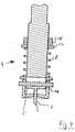
- Fig. 7 shows a pressing device 4, in which a Holder 16 for the carrier mandrel 5 and the guide pin. 6 can be prestressed by means of a spring unit 8.
- a Nut 18 and an abutment 17 is the biasing force of Spring unit 8 adjustable.
- FIG. 8 A further embodiment of the pressing unit 4 results from Fig. 8.
- the carrier 5 by means of a piston-cylinder unit 7 prestressed, which via a line 19 can be acted upon with compressed air or hydraulic fluid.
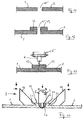
- Figs. 9 and 10 respectively show embodiments of Edge regions of the tubular elements 1, 2. These are each as Flange portions 12, 13 formed and configured so that Engagement elements 10, 11 are releasably engageable.
- the flange portions 12, 13 in the manner of a "dovetail guide” forms they include beveled guide surfaces 21, 22, in FIG which wedge-shaped engagement elements 10, 11 can be inserted are.
- FIGS. 11 to 13 show a further variant in which the flange portions 12, 13 by forming the free ends the tubular elements 1, 2 are formed to a subsequent To allow welding.
- the flange portions 12, 13 serve both the leadership as well as the generation of a sufficient thick wall layer of the tubular elements.
- the pipe robot 24 with suitable camera and sensor means is equipped to ensure accurate positioning the Reibsch conductedorns 3 ermony. After completion the Reibsch bulkvorgangs (rotation of the carrier 27 to 360 ° about the axis 28) of the Reibsch conducteddorns 3 is something again withdrawn and from the wall of the tubular elements 1, 2 solved. Subsequently, the pipe robot 24 can be moved.
Landscapes
- Engineering & Computer Science (AREA)
- Mechanical Engineering (AREA)
- Physics & Mathematics (AREA)
- Fluid Mechanics (AREA)
- Lining Or Joining Of Plastics Or The Like (AREA)
Abstract
Description
Die Erfindung bezieht sich auf eine Vorrichtung zum Verschweißen von Rohrelementen aus thermoplastischen Kunststoffen.The invention relates to a device for welding of tubular elements made of thermoplastic materials.
Rohrelemente der genannten Art werden insbesondere bei der Sanierung von schadhaften Kanalisationsleitungen verwendet. Dabei werden die Rohrelemente oder Rohrmodule ohne Freilegen der Kanalisationsleitungen in diese eingepresst bzw. eingezogen. Diese Verfahren werden auch als Relining-Verfahren bezeichnet. Hierdurch ist es möglich, aufwendige Erdarbeiten zu vermeiden. Es ist lediglich erforderlich, an einer Stelle einen Schacht zu graben, durch den die Rohrelemente oder Rohrmodule in den vorhandenen, gemauerten oder aus Elementen anderer Art bestehenden, schadhaften Kanal, einzuführen.Pipe elements of the type mentioned are particularly in the Renovation of damaged sewage pipes used. The pipe elements or pipe modules are exposed without exposure the sewer lines pressed into this or retracted. These procedures are also called relining procedures designated. This makes it possible, elaborate earthworks to avoid. It is only necessary in one place to dig a shaft through which the pipe elements or Pipe modules in the existing, bricked or elements different kind of damaged channel.
In ähnlicher Weise werden auch in einen Kanal einmündende Hausanschlüsse saniert. Hierbei wird ein Schlauch oder Hütchen durch den zuvor mittels eines Roboters ausgefrästen Zugang zu dem Hausanschluss eingesetzt und entsprechend mit dem Rohrelement verbunden.Similarly, also entering a channel House connections renovated. This is a hose or hat through the previously milled by a robot access used to the house connection and accordingly with connected to the pipe element.
Es sind auch bereits Vorschläge zum Verkleben von Muffenverbindungen
von Polyäthylen-Rohren gemacht worden, beispielsweise
in der deutschen Patentschrift 10 12 013. Das dort beschriebene
Klebematerial hat sich in der Praxis aus unterschiedlichsten
Gründen nicht durchsetzen können.There are also proposals for bonding socket joints
made of polyethylene pipes, for example
in
Die übliche, beim Stand der Technik verwendete Vorgehensweise liegt darin, die einzelnen Rohrelemente mechanisch aneinander zu verrasten, wobei zusätzliche Dichtungsringe oder Ähnliches eingelegt werden können. Diese Vorgehensweise ist mit relativ hohen Kosten verbunden, da die Herstellung der einzelnen Rohrelemente, insbesondere deren Verrastungsbereiche, sehr aufwendig ist. Rohrelemente der beschriebenen Art werden üblicherweise extrudiert oder nach sonstigen Rohrherstellungsverfahren gefertigt. Somit müssen die Verbindungselemente in separaten Arbeitsgängen hergestellt werden.The usual procedure used in the prior art lies in it, the individual pipe elements mechanically together to lock, with additional sealing rings or Similar can be inserted. This procedure is associated with relatively high costs, since the production of the individual pipe elements, in particular their Verrastungsbereiche, very expensive. Pipe elements of the type described are usually extruded or after other tube manufacturing processes manufactured. Thus, the fasteners must be made in separate operations.
Zum Anschluss von Hauselementen ist es bekannt, eine Verschweißung durch Heizleiterwendel zu realisieren. Die Heizleiterwendeln sind üblicherweise in die Verbindungsbereiche eingeklebt oder dort vormontiert. Zum Einsetzen der Rohrelemente ist es erforderlich, diese auf Rohrroboter aufzusetzen, an die gewünschte Stelle zu verfahren und anschließend solange zu beheizen, bis der Schweißvorgang beendet ist. Als besonders nachteilig erweist es sich, dass hohe elektrische Leistungen über einen längeren Zeitraum erforderlich sind, wo insbesondere der elektrische Anschluss und die Kontaktierung der Heizleiterwendel technisch aufwendig und anspruchsvoll ist. Diese Vorgehensweise ist beispielsweise in der EP 674 131 B1 beschrieben.For the connection of house elements, it is known a weld to realize by Heizleiterwendel. The heating conductor spirals are usually in the connection areas glued or preassembled there. For inserting the pipe elements it is necessary to put these on pipe robots, to move to the desired location and then to heat until the welding process is completed. When It is particularly disadvantageous that high electrical Services are required over a longer period, where in particular the electrical connection and the contact the Heizleiterwendel technically complex and sophisticated is. This procedure is for example in the EP 674 131 B1.
Zum Verschweißen von thermoplastischen Bauteilen zeigt die US 5,460,317 A, dass im Fügebereich thermoplastischer Werkstücke mittels eines Reibschweißdorns ein ausreichender Energieeintrag erzielt werden kann, um die Randbereiche zu verschweißen.For welding thermoplastic components shows the US 5,460,317 A that in the joining area of thermoplastic workpieces by means of a Reibschweißdorns a sufficient Energy input can be achieved to the edge areas too weld.
Der Erfindung liegt die Aufgabe zu Grunde, eine Vorrichtung sowie ein Verfahren der eingangs genannten Art zu schaffen, welche bei einfacher, kostengünstiger Umsetzbarkeit die Verweißung von thermoplastischen Kunststoffrohren zu ermöglichen.The invention is based on the object, a device and to provide a method of the type mentioned, which with simple, cost-effective implementation of the weld to allow thermoplastic pipes.
Erfindungsgemäß wird die Aufgabe durch die Merkmale des Hauptanspruchs bzw. des nebengeordneten Anspruchs gelöst, die jeweiligen Unteransprüche zeigen weitere vorteilhafte Ausgestaltungen der Erfindung.According to the invention the object is achieved by the features of Main claim or the independent claim dissolved, the respective subclaims show further advantageous Embodiments of the invention.
Die Erfindung zeichnet sich durch eine Reihe erheblicher Vorteile aus. Zum Verschweißen von thermoplastischen Rohren, insbesondere PE-Rohren, kann auf einfachste Weise ein üblicher, zur Sanierung von Rohren vorhandener Rohrroboter eingesetzt werden. Dieser wird mit einem entsprechenden Arbeitsaufsatz versehen, der die Antriebseinheit, die Steuereinheit sowie entsprechende Manipulationsvorrichtungen umfasst. Somit ist es möglich, den Rohrroboter an beliebigen Stellen innerhalb des Rohres zu verfahren, dort den Reibschweißdorn in Drehung zu versetzen und an der zurverschwei-ßenden Schweißnaht zu positionieren. Insbesondere beim Stumpf-Verschweißen von Rohren oder Rohrelementen bedarf es nur einfacher Steuerungsmechanismen, die entweder elektronisch mittels Stellmotoren oder mechanisch mittels Bahnkurven oder ähnlichem realisiert werden können.The invention is characterized by a number of significant Advantages. For welding thermoplastic pipes, PE pipes in particular, can easily be a common, used for the rehabilitation of pipes existing pipe robots become. This is with a corresponding work attachment provided, the drive unit, the control unit and corresponding manipulation devices. Thus, it is possible, the pipe robot at any To move within the tube, there the Reibschweißdorn to turn and at the verschwei-ßenden Position weld. Especially when Butt welding of pipes or pipe elements is required just simple control mechanisms, either electronic by means of servo motors or mechanically by means of trajectories or the like can be realized.
Der wesentliche Vorteil der erfindungsgemäßen Vorrichtung besteht darin, dass keine zusätzliche Energie eingebracht werden muss, wie etwa elektrische Energie bei elektrischen Schweißmuffen. Somit kann der Rohrroboter den Reibschweißvorgang auch mit einem pneumatischen oder hydraulischen Antrieb realisieren. Hierdurch vereinfacht sich die gesamte Handhabung. Weiterhin können explosionsgeschützte Vorrichtungen verwendet werden.The main advantage of the device according to the invention is that no additional energy introduced must be, such as electrical energy in electrical Welding sleeves. Thus, the pipe robot can friction weld also with a pneumatic or hydraulic drive realize. This simplifies the whole Handling. Furthermore, explosion-proof devices be used.
Durch die Verwendung des erfindungsgemäßen Reibschweißverfahrens, welches aus der Verwendung der erfindungsgemäßen Vorrichtung resultiert, kann der Energieeintrag exakt in Abhängigkeit von den jeweiligen Gegebenheiten gesteuert werden. Hierzu kann der Reibschweißdorn entsprechend dimensioniert werden. Weiterhin ist es möglich, seine Drehgeschwindigkeit sowie die Vorschubgeschwindigkeit entsprechend anzupassen.By using the friction welding method according to the invention, which from the use of the invention Device results, the energy input can be exactly in dependence be controlled by the respective circumstances. For this purpose, the friction welding mandrel can be dimensioned accordingly become. Furthermore, it is possible his speed of rotation and adjust the feed rate accordingly.
Der Einsatz des Reibschweißdorns ist auch im Wesentlichen unabhängig von äußeren Einflüssen, sodass Feuchtigkeit, insbesondere höhere Luftfeuchtigkeit oder Ähnliches, den Schweißvorgang nicht beeinträchtigen.The use of the Reibschweißdorns is also essentially regardless of external influences, so that moisture, in particular higher humidity or similar, the Do not interfere with the welding process.
In besonders günstiger Ausgestaltung der Erfindung ist vorgesehen, dass der Reibschweißdorn einen drehbar gelagerten Trägerdorn mit einem Führungszapfen umfasst. Der Führungs-zapfen kann so dimensioniert werden, dass er innerhalb der Trennfuge der zu verbindenden Rohrelemente geführt wird und somit die Bewegungsbahn des Reibschweißdorns automatisch steuert.In a particularly advantageous embodiment of the invention is provided that the Reibschweißdorn a rotatably mounted Carrier mandrel with a guide pin comprises. The guide pin can be sized to fit within the Parting line of the pipe elements to be connected is performed and thus the trajectory of the Reibschweißdorns automatically controls.
Um einen ausreichenden Anpressdruck des Reibschweißdorns gegen die zu verschweißenden Rohrwandungen sicherzustellen, kann dieser mittels einer Kolben-Zylinder-Einheit vorgespannt sein. Eine Vorspannung ist auch über eine Federeinheit oder durch andere Maßnahmen möglich. Besonders günstig ist es, wenn der Reibschweißdorn an einer Führungseinheit gelagert ist, welche mit Eingriffselementen versehen ist, welche mit einem Flanschbereich des jeweiligen Rohrelements in Eingriff bringbar sind. Hierdurch wird die Bewegung des Reibschweißdorns entlang der Trennfuge weiter vereinfacht bzw. sichergestellt.To a sufficient contact pressure of the Reibschweißdorns against to ensure the pipe walls to be welded this can be biased by means of a piston-cylinder unit be. A bias is also a spring unit or by other means possible. Very cheap it is when the Reibschweißdorn on a guide unit is mounted, which is provided with engagement elements, which with a flange portion of the respective pipe element can be brought into engagement. This will cause the movement of the Friction welding mandrel further simplified along the parting line or ensured.
Im Folgenden wird die Erfindung anhand von Ausführungsbeispielen in Verbindung mit der Zeichnung beschrieben. Dabei zeigt:
- Fig. 1
- eine schematische Darstellung der Funktionsweise des Reibschweißdorns,
- Fig. 2
- eine Seitenansicht, teils im Schnitt, der in Fig. 1 gezeigten Anordnung,
- Fig. 3
- eine Draufsicht auf die in Fig. 1 gezeigte Anordnung,
- Fig. 4-6
- unterschiedliche Ausgestaltungen des Führungszapfens,
- Fig. 7
- eine schematische Teil-Schnittansicht einer Anpresseinheit für den Reibschweißdorn,
- Fig. 8
- eine weitere Ausgestaltung einer Anpresseinheit für den Reibschweißdorn,
- Fig. 9
- eine Seltenansicht einer erfindungsgemäßen Führungseinheit,
- Fig. 10
- eine Teil-Seitenansicht eines weiteren Ausführungsbeispiels einer Führungseinheit,
- Fig. 11-13
- Seiten-Schnittansichten, in welchen der Arbeitsablauf dargestellt ist,
- Fig. 14
- eine schematische Seiten-Schnittansicht eines Ausführungsbeispiels eines Rohrroboters mit der erfindungsgemäßen Vorrichtung, und
- Fig. 15
- eine vereinfachte Teil-Schnittansicht eines Hausanschlusses zur Verschweißung mit der erfindungsgemäßen Vorrichtung.
- Fig. 1
- a schematic representation of the operation of the Reibschweißdorns,
- Fig. 2
- a side view, partly in section, of the arrangement shown in Fig. 1,
- Fig. 3
- a plan view of the arrangement shown in Fig. 1,
- Fig. 4-6
- different embodiments of the guide pin,
- Fig. 7
- a schematic partial sectional view of a Anpress unit for the Reibschweißdorn,
- Fig. 8
- a further embodiment of a pressing unit for the Reibschweißdorn,
- Fig. 9
- a rare view of a guide unit according to the invention,
- Fig. 10
- a partial side view of another embodiment of a guide unit,
- Fig. 11-13
- Page views in which the workflow is shown
- Fig. 14
- a schematic side sectional view of an embodiment of a pipe robot with the device according to the invention, and
- Fig. 15
- a simplified partial sectional view of a house connection for welding with the device according to the invention.
Die Fig. 1 zeigt in perspektivischer Darstellung Teile von
Rohrelementen 1, 2 sowie einen drehbar gelagerten Reibschweißdorn
3, welcher einen Trägerdorn 5 aufweist, von dessen
ebener Stirnfläche 14 aus sich ein Führungszapfen 6 erstreckt,
der längs einer Fuge 15 zwischen den zu verbindenden
Rohrelementen 1, 2 bewegbar ist. Durch die Reibung des
Führungszapfens 6 sowie der Stirnfläche 14 des Trägerdorns 3
erfolgt ein Energieeintrag beim Vorschub bzw. bei der Drehung
des Reibschweißdorns 3.Fig. 1 shows in perspective parts of
Die Fig. 2 und 3 zeigen eine Seiten-Ansicht bzw. eine Draufsicht der in Fig. 1 gezeigten Anordnung.Figs. 2 and 3 show a side view and a top view, respectively the arrangement shown in Fig. 1.
Aus den Fig. 4 bis 6 ergeben sich unterschiedliche Formen
des Führungszapfens 6.From FIGS. 4 to 6, different shapes result
of the
Die Fig. 7 zeigt eine Anpresseinrichtung 4, bei welcher eine
Halterung 16 für den Trägerdorn 5 bzw. den Führungszapfen 6
mittels einer Federeinheit 8 vorspannbar ist. Mittels einer
Mutter 18 und eines Widerlagers 17 ist die Vorspannkraft der
Federeinheit 8 einstellbar.Fig. 7 shows a pressing device 4, in which a
Eine weitere Ausgestaltung der Anpresseinheit 4 ergibt sich
aus Fig. 8. Dort ist der Träger 5 mittels einer Kolben-Zylinder-Einheit
7 vorspannbar, welche über eine Leitung 19
mit Pressluft oder Hydraulikfluid beaufschlagt werden kann.A further embodiment of the pressing unit 4 results
from Fig. 8. There is the
Es versteht sich, dass die Abbildungen 7 und 8 die drehbare
Lagerung sowie den Antrieb des Reibschweißdorns 3 nicht im
Einzelnen darstellen.It is understood that Figures 7 and 8, the rotatable
Storage and the drive of the
Die Fig. 9 und 10 zeigen jeweils Ausgestaltungsformen von
Randbereichen der Rohrelemente 1, 2. Diese sind jeweils als
Flanschbereiche 12, 13 ausgebildet und so ausgestaltet, dass
Eingriffselemente 10, 11 lösbar in Eingriff bringbar sind.Figs. 9 and 10 respectively show embodiments of
Edge regions of the
Bei dem Ausführungsbeispiel der Fig. 9 sind die Eingriffselemente
10, 11 in Form von Rollen ausgebildet, die an
Schlitten 20 gelagert sind, die relativ zu einem Träger verstellt
werden können. Somit ist es möglich, die Flanschbereiche
12, 13 zu greifen und die gesamte Anordnung an diesen
zu führen.In the embodiment of Fig. 9, the
Bei dem Ausführungsbeispiel der Fig. 10 sind die Flanschbereiche
12, 13 in Art einer "Schwalbenschwanzführung" ausge-bildet,
sie umfassen abgeschrägte Führungsflächen 21, 22, in
welche keilförmige Eingriffselemente 10, 11 einschiebbar
sind.In the embodiment of Fig. 10, the
Mit dem Bezugszeichen 23 ist in Fig. 10 der Schweißbereich
oder Fügebereich dargestellt.The
Die Fig. 11 bis 13 zeigen eine weitere Variante, bei welcher
die Flanschbereiche 12, 13 durch Umformen der freien Enden
der Rohrelemente 1, 2 gebildet werden, um eine nachfolgende
Verschweißung zu ermöglichen. Die Flanschbereiche 12, 13
dienen sowohl der Führung als auch zur Erzeugung einer ausreichend
dicken Wandschicht der Rohrelemente.FIGS. 11 to 13 show a further variant in which
the
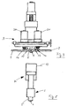
Die Fig. 14 zeigt in schematischer Seiten-Schnittansicht
zwei coaxial miteinander zu verbindende Rohrelemente 1, 2,
die an der Fuge 15 aneinander liegen und dort verschweißt
werden sollen.Fig. 14 shows a schematic side sectional view
two
In dem Rohrelement 2 ist ein Rohrroboter 24 angeordnet, welcher
im gezeigten Ausführungsbeispiel aus vier gelenkig miteinander
verbundenen Teilkörpern besteht. Diese sind jeweils
mit Rädern 25 versehen, welche drehbar und angetrieben an
Radträgern 26 lagern, welche wiederum zu den einzelnen Elementen
des Rohrroboters 24 verschwenkbar sind. Auf diese
Weise ist eine Anpassung an unterschiedliche Durchmesser des
Rohrelements 2 möglich. Gleichzeitig ist eine Vorschub- bzw.
Rückfahrbewegung möglich. Es versteht sich, dass die Ausgestaltung
des Rohrroboters 24 im Rahmen der Erfindung in weitem
Bereich verändert werden kann. Erfindungsgemäß können
übliche Rohrroboter eingesetzt werden, die hinsichtlich ihrer
Dimensionierung, ihres Antriebs etc., den Anforderungen
angepasst werden können.In the
Bei dem gezeigten Ausführungsbeispiel ist am vorderen Ende
des vorderen Elements des Rohrroboters 24 ein Träger 27 angeordnet,
welcher um eine zentrische Achse 28 drehbar ist.
Die Achse 28 ist bevorzugter Weise zentrisch zu dem Rohrelement
2 bzw. zu dem ebenfalls axial angeordneten Rohrelement
1 sowie zusätzlich zentrisch zu dem Rohrroboter 24 angeordnet.
Der Träger 27 ist mittels eines nicht dargestellten Antriebs
so um die Achse 28 schwenkbar, dass eine Kreisbewegung
entlang der Fuge 15 möglich ist.In the embodiment shown is at the front end
the front element of the
An dem Träger 27 ist, wie schematisch dargestellt, drehbar
ein Trägerdorn 5 gelagert. Der Drehantrieb sowie eine Vorrichtung
zum Vorspannen des Trägerdorns 5 sind nicht gezeigt.
Die Vorrichtung zum Vorspannen kann beispielsweise
analog der Ausführung der Fig. 8 (Kolben-Zylinder-Einheit)
oder analog der Vorrichtung gemäß Fig. 7 (Federvorspannung)
ausgebildet sein. Die Darstellung der Fig. 14 zeigt den Trägerdorn
15 in einer zurückgezogenen Position, in welcher er
nicht gegen die Wandung der Rohrelemente 1, 2 anliegt. Hierdurch
ist auch der Führungszapfen 6 sichtbar, der an der
freien Endfläche des Trägerdorns 5 angeordnet ist. On the
Die Arbeitsweise des in Fig. 14 gezeigten Rohrroboters ist
so, dass dieser entlang des Rohrelements 2 so verfahren
wird, dass sich die Achse 29, um welche sich der Trägerdorn
5 dreht, fluchtend zu der Ebene der Fuge 15 befindet. Daraufhin
wird der Trägerdorn 5, zusammen mit dem Führungszapfen
6, mittels der nicht gezeigten Antriebseinrichtung in
schnelle Drehung um die Achse 29 versetzt. Gleichzeitig wird
der Trägerdorn 5 nach vorne verfahren, sodass er gegen die
Wandung der Rohrelemente 1, 2 anliegt. Nunmehr erfolgt eine
Drehung des Trägers 27 um die Achse 28. Hierdurch fährt der
Trägerdorn 5 (der einen Teil des Reibschweißdorns 3 bildet)
längs der Fuge 15 am Umfang der Rohrelemente 1, 2 vorbei und
verschweißt diese.The operation of the pipe robot shown in Fig. 14 is
such that it moves along the
Es versteht sich, dass der Rohrroboter 24 mit geeigneten Kamera-
und Sensormitteln ausgestattet ist, um eine exakte Positionierung
des Reibschweißdorns 3 zu ermöglichlen. Nach Beendung
des Reibschweißvorgangs (Drehung des Trägers 27 um
360° um die Achse 28) wird der Reibschweißdorns 3 wieder etwas
zurückgezogen und von der Wandung der Rohrelemente 1, 2
gelöst. Nachfolgend kann der Rohrroboter 24 verfahren werden.It is understood that the
Die Fig. 15 zeigt in schematischer Weise einen Teilschnitt
durch ein Rohrelement 1 bzw. 2, welches in ein zu sanierendes
Kanalrohr 30 eingeschoben ist. Im Bereich eines Hausanschlussrohrs
31 ist das Rohrelement 1, 2 ausgefräst, so wie
dies aus dem Stand der Technik üblich ist. In das Hausanschlussrohr
31 ist ein thermoplastisches Rohrelement 32 eingesetzt.
Die Fig. 15 zeigt zwei unterschiedliche Ausgestaltungsformen.
Bei der linken Bildhälfte ist das Rohrelement
32 bündig mit der Ausfräsung des Rohrelements 1, 2 ausgebildet,
während bei der rechten Bildhälfte der Fig. 15 das
Rohrelement 32 mit einem Flansch 33 versehen ist. In beiden
Fällen ergibt sich eine ringförmige Fuge 15, die mittels der
erfindungsgemäßen Vorrichtung, d.h. mittels des Reibschweißdorns
3 zu verschweißen ist. Hierbei muss der Reibschweißdorn
auf einer Kreisbahn um die Mittelachse 34 des Rohrelements
32 längs der Fuge 15 bewegt werden. Hierzu benötigt
der Rohrroboter 24 an dem Träger 27 einen weiteren Aufsatz,
der hinsichtlich seiner Achse zu der Mittelachse 34 positioniert
ist und dementsprechend den Reibschweißdorn 3 auf der
Kreisbahn längs der Fuge 15 bewegt. Es versteht sich, dass
bei entsprechender Konstruktion auch schräge oder geneigte
Hausanschlüsse in Rohrelemente eingeschweißt werden können.Fig. 15 shows schematically a partial section
by a
Claims (5)
Priority Applications (1)
| Application Number | Priority Date | Filing Date | Title |
|---|---|---|---|
| EP03025628A EP1529624A1 (en) | 2003-11-06 | 2003-11-06 | Device for welding thermoplastic pipe elements |
Applications Claiming Priority (1)
| Application Number | Priority Date | Filing Date | Title |
|---|---|---|---|
| EP03025628A EP1529624A1 (en) | 2003-11-06 | 2003-11-06 | Device for welding thermoplastic pipe elements |
Publications (1)
| Publication Number | Publication Date |
|---|---|
| EP1529624A1 true EP1529624A1 (en) | 2005-05-11 |
Family
ID=34429301
Family Applications (1)
| Application Number | Title | Priority Date | Filing Date |
|---|---|---|---|
| EP03025628A Withdrawn EP1529624A1 (en) | 2003-11-06 | 2003-11-06 | Device for welding thermoplastic pipe elements |
Country Status (1)
| Country | Link |
|---|---|
| EP (1) | EP1529624A1 (en) |
Cited By (4)
| Publication number | Priority date | Publication date | Assignee | Title |
|---|---|---|---|---|
| CN102494662A (en) * | 2011-12-19 | 2012-06-13 | 武汉华之洋光电系统有限责任公司 | Oil tube deformation detecting device |
| GB2545223A (en) * | 2015-12-09 | 2017-06-14 | Rtl Mat Ltd | Apparatus and methods for joining in a tube |
| CN110253176A (en) * | 2019-05-30 | 2019-09-20 | 株洲湘江电焊条有限公司 | Welding rod and preparation method thereof suitable for AC power source welding natural gas storage tank |
| GB2608136A (en) * | 2021-06-22 | 2022-12-28 | Pinweld Ltd | Polymeric pipe welding apparatus |
Citations (8)
| Publication number | Priority date | Publication date | Assignee | Title |
|---|---|---|---|---|
| DE9109412U1 (en) * | 1990-08-10 | 1991-10-17 | Henze Gmbh Kunststoffwerk, 5210 Troisdorf, De | |
| DE4128818A1 (en) * | 1991-08-30 | 1993-03-04 | Stehmeyer & Bischoff Gmbh Co | Plastic pipe section welding system for repairing sewers, etc. - in which external coil with internal contacts is used for travelling truck |
| US5392715A (en) * | 1993-10-12 | 1995-02-28 | Osaka Gas Company, Ltd. | In-pipe running robot and method of running the robot |
| US5460317A (en) * | 1991-12-06 | 1995-10-24 | The Welding Institute | Friction welding |
| JPH11226756A (en) * | 1998-02-09 | 1999-08-24 | Nippon Light Metal Co Ltd | Production method of cylinder with use of friction agitation joining and production device to be used for its method |
| JPH11300480A (en) * | 1998-04-16 | 1999-11-02 | Kobe Steel Ltd | Vacuum chamber for semiconductor manufacturing device and its manufacture |
| JP2001025886A (en) * | 1999-07-15 | 2001-01-30 | Nissho Iwai Hitetsu Hanbai Kk | Joining method of separated pieces for storage tank |
| DE10238550A1 (en) * | 2002-08-22 | 2004-03-18 | Weber, Joachim, Dr. | Friction welding unit for thermoplastic pipes comprises a pipe robot, a drive unit, a control unit for moving a friction welding mandrel and a press unit which presses the mandrel onto the inner pipe wall |
-
2003
- 2003-11-06 EP EP03025628A patent/EP1529624A1/en not_active Withdrawn
Patent Citations (9)
| Publication number | Priority date | Publication date | Assignee | Title |
|---|---|---|---|---|
| DE9109412U1 (en) * | 1990-08-10 | 1991-10-17 | Henze Gmbh Kunststoffwerk, 5210 Troisdorf, De | |
| DE4128818A1 (en) * | 1991-08-30 | 1993-03-04 | Stehmeyer & Bischoff Gmbh Co | Plastic pipe section welding system for repairing sewers, etc. - in which external coil with internal contacts is used for travelling truck |
| US5460317A (en) * | 1991-12-06 | 1995-10-24 | The Welding Institute | Friction welding |
| US5460317B1 (en) * | 1991-12-06 | 1997-12-09 | Welding Inst | Friction welding |
| US5392715A (en) * | 1993-10-12 | 1995-02-28 | Osaka Gas Company, Ltd. | In-pipe running robot and method of running the robot |
| JPH11226756A (en) * | 1998-02-09 | 1999-08-24 | Nippon Light Metal Co Ltd | Production method of cylinder with use of friction agitation joining and production device to be used for its method |
| JPH11300480A (en) * | 1998-04-16 | 1999-11-02 | Kobe Steel Ltd | Vacuum chamber for semiconductor manufacturing device and its manufacture |
| JP2001025886A (en) * | 1999-07-15 | 2001-01-30 | Nissho Iwai Hitetsu Hanbai Kk | Joining method of separated pieces for storage tank |
| DE10238550A1 (en) * | 2002-08-22 | 2004-03-18 | Weber, Joachim, Dr. | Friction welding unit for thermoplastic pipes comprises a pipe robot, a drive unit, a control unit for moving a friction welding mandrel and a press unit which presses the mandrel onto the inner pipe wall |
Non-Patent Citations (3)
| Title |
|---|
| PATENT ABSTRACTS OF JAPAN vol. 1999, no. 13 30 November 1999 (1999-11-30) * |
| PATENT ABSTRACTS OF JAPAN vol. 2000, no. 02 29 February 2000 (2000-02-29) * |
| PATENT ABSTRACTS OF JAPAN vol. 2000, no. 16 8 May 2001 (2001-05-08) * |
Cited By (8)
| Publication number | Priority date | Publication date | Assignee | Title |
|---|---|---|---|---|
| CN102494662A (en) * | 2011-12-19 | 2012-06-13 | 武汉华之洋光电系统有限责任公司 | Oil tube deformation detecting device |
| GB2545223A (en) * | 2015-12-09 | 2017-06-14 | Rtl Mat Ltd | Apparatus and methods for joining in a tube |
| US11142964B2 (en) | 2015-12-09 | 2021-10-12 | RTL Materials Limited | Apparatus and method for joining in a tube |
| CN110253176A (en) * | 2019-05-30 | 2019-09-20 | 株洲湘江电焊条有限公司 | Welding rod and preparation method thereof suitable for AC power source welding natural gas storage tank |
| CN110253176B (en) * | 2019-05-30 | 2021-06-25 | 株洲湘江电焊条有限公司 | Welding electrode suitable for AC power supply to weld natural gas storage tank and preparation method thereof |
| GB2608136A (en) * | 2021-06-22 | 2022-12-28 | Pinweld Ltd | Polymeric pipe welding apparatus |
| WO2022269238A1 (en) * | 2021-06-22 | 2022-12-29 | Pinweld Limited | Polymeric pipe welding apparatus |
| GB2608136B (en) * | 2021-06-22 | 2024-01-03 | Pinweld Ltd | Polymeric pipe welding apparatus |
Similar Documents
| Publication | Publication Date | Title |
|---|---|---|
| EP0158042A2 (en) | Device for incorporating plastic tubes into sewers | |
| EP2044356B1 (en) | Device and method for incorporating pipelines into pipeline transport systems | |
| EP0023005A1 (en) | Tool for the production of a tube-connection | |
| EP1703187B1 (en) | Device for axial alignment of pipe sections | |
| DE3604677A1 (en) | METHOD AND HOLDING DEVICE FOR THE PRODUCTION OF RODS CONSISTING OF RING ELEMENTS | |
| DE102011012198A1 (en) | Method for welding plastic pipe at e.g. pipe branches in mine operations, involves welding pipe pieces over pipe connection piece, and canceling clamping process according to cooling of weld zone at pipe pieces and pipe connection piece | |
| DE1105539B (en) | Centering device for arc welding pipe joints | |
| DE10238550B4 (en) | Device for welding thermoplastic pipe elements | |
| DE4238700C2 (en) | Device for fastening connecting elements to pipes | |
| EP2048426A2 (en) | Tapping fitting | |
| WO1995007168A1 (en) | Tool-change device for manipulators | |
| DE19714463A1 (en) | Tube cleaning device | |
| DE2544723A1 (en) | RAIL WELDING DEVICE | |
| DE102006026275A1 (en) | Device for deforming, positioning and processing pipelines | |
| DE2328080B2 (en) | Device for centering and holding a smooth flange to be welded to a pipe | |
| EP1529624A1 (en) | Device for welding thermoplastic pipe elements | |
| EP0905433B1 (en) | Method and device for installing, positioning and fixing of parts in cavities of diverging cross sections | |
| DE2903847C2 (en) | ||
| DE2624013C2 (en) | Pipe or hose coupling | |
| DE2406661A1 (en) | HEATING PLATE FOR HEATING THE FREE END OF PLASTIC PIPE BODIES | |
| DE10226747A1 (en) | Base body of joined pipe pieces consists of two welded pipes in form of pipe-connector combination with weld seam surfaces that are mating, saddle-shaped and parallel to each other | |
| DE4128818C2 (en) | Process for connecting pieces of pipe made of plastic and carriage | |
| EP1703186B1 (en) | Device and method for connecting pipe sections and pipeline produced with such method | |
| DE3501421A1 (en) | Apparatus for making orifices in pipe walls | |
| DE19527048C2 (en) | Device for carrying out electron beam technological processes |
Legal Events
| Date | Code | Title | Description |
|---|---|---|---|
| PUAI | Public reference made under article 153(3) epc to a published international application that has entered the european phase |
Free format text: ORIGINAL CODE: 0009012 |
|
| AK | Designated contracting states |
Kind code of ref document: A1 Designated state(s): AT BE BG CH CY CZ DE DK EE ES FI FR GB GR HU IE IT LI LU MC NL PT RO SE SI SK TR |
|
| AX | Request for extension of the european patent |
Extension state: AL LT LV MK |
|
| AKX | Designation fees paid | ||
| STAA | Information on the status of an ep patent application or granted ep patent |
Free format text: STATUS: THE APPLICATION IS DEEMED TO BE WITHDRAWN |
|
| 18D | Application deemed to be withdrawn |
Effective date: 20051112 |
|
| REG | Reference to a national code |
Ref country code: DE Ref legal event code: 8566 |