EP1530049A1 - Device for measuring the velocity of a projectile, in particular the muzzle velocity - Google Patents
Device for measuring the velocity of a projectile, in particular the muzzle velocity Download PDFInfo
- Publication number
- EP1530049A1 EP1530049A1 EP04026010A EP04026010A EP1530049A1 EP 1530049 A1 EP1530049 A1 EP 1530049A1 EP 04026010 A EP04026010 A EP 04026010A EP 04026010 A EP04026010 A EP 04026010A EP 1530049 A1 EP1530049 A1 EP 1530049A1
- Authority
- EP
- European Patent Office
- Prior art keywords
- sensors
- weapon barrel
- projectile
- barrel
- recesses
- Prior art date
- Legal status (The legal status is an assumption and is not a legal conclusion. Google has not performed a legal analysis and makes no representation as to the accuracy of the status listed.)
- Withdrawn
Links
Images

Classifications
-
- G—PHYSICS
- G01—MEASURING; TESTING
- G01P—MEASURING LINEAR OR ANGULAR SPEED, ACCELERATION, DECELERATION, OR SHOCK; INDICATING PRESENCE, ABSENCE, OR DIRECTION, OF MOVEMENT
- G01P3/00—Measuring linear or angular speed; Measuring differences of linear or angular speeds
- G01P3/64—Devices characterised by the determination of the time taken to traverse a fixed distance
- G01P3/66—Devices characterised by the determination of the time taken to traverse a fixed distance using electric or magnetic means
- G01P3/665—Devices characterised by the determination of the time taken to traverse a fixed distance using electric or magnetic means for projectile velocity measurements
-
- F—MECHANICAL ENGINEERING; LIGHTING; HEATING; WEAPONS; BLASTING
- F41—WEAPONS
- F41A—FUNCTIONAL FEATURES OR DETAILS COMMON TO BOTH SMALLARMS AND ORDNANCE, e.g. CANNONS; MOUNTINGS FOR SMALLARMS OR ORDNANCE
- F41A21/00—Barrels; Gun tubes; Muzzle attachments; Barrel mounting means
- F41A21/32—Muzzle attachments or glands
Landscapes
- Engineering & Computer Science (AREA)
- General Engineering & Computer Science (AREA)
- Physics & Mathematics (AREA)
- General Physics & Mathematics (AREA)
- Aiming, Guidance, Guns With A Light Source, Armor, Camouflage, And Targets (AREA)
- Measuring Fluid Pressure (AREA)
Abstract
Description
Aus der CH 691 143 A5 ist eine Vorrichtung zur Messung der Geschossgeschwindigkeit an der Mündung eines Waffenrohres eines Geschützes hoher Kadenz bekannt. Dieses umfasst zwei in einem Abstand voneinander an einem Tragrohr angeordnet, auf Veränderung eines magnetischen Flusses ansprechende Sensoren, die mit einer Auswerteelektronik in Verbindung stehen. Dabei weist jeder Sensor ein Spulenpaar aus zwei Spulen und einem geschossenen magnetischen Kreis auf.From CH 691 143 A5 a device for measuring the projectile velocity is on the mouth of a barrel of a gun high cadence known. This includes two arranged at a distance from each other on a support tube, to change a magnetic flux responsive sensors, which communicate with evaluation electronics stand. Each sensor has a coil pair of two coils and a shot magnetic circuit.
In der DE 697 09 291 T2 (EP 0 840 087 B1) werden Mittel zur Steuerung der Anfangsgeschwindigkeit eines Geschosses offenbart. Dabei ist ein Sensormittel vorgesehen, das einen auf die Mündungsgeschwindigkeit bezogenen Parameter messen kann. Dies erfolgt mit Hilfe der zumindest im bzw. am Waffenlauf angebrachten Sensoren, die einen höheren Druck im Waffenlauf aufnehmen können, welcher sich durch das Erhitzen der Treibgase am Waffenrohr einstellt. Als Sensoren werden Dehnungsmessstreifen vorgeschlagen, die so angepasst sind, dass sie Kontakt mit dem Waffenlauf haben. Dadurch soll leicht die Ausdehnungen des Waffenlaufs gemessen werden können. Aus der zeitlichen Differenz zwischen der Registrierung der Projektilpassage durch die beiden einzelnen Sensoren wird die Bewegung und damit die Geschwindigkeit des Projektils ermittelt.DE 697 09 291 T2 (EP 0 840 087 B1) discloses means for controlling the initial speed of a projectile. In this case, a sensor means is provided, the one can measure the muzzle velocity related parameter. This is done with help the at least in or on the barrel mounted sensors, the higher pressure in the Gun run record, which is characterized by the heating of the propellant gases on the barrel established. As sensors strain gauges are proposed, which are adapted are that they have contact with the gun barrel. This should be easy the expansions of Arms race can be measured. From the time difference between the registration the projectile passage through the two individual sensors becomes the movement and thus determines the speed of the projectile.
Aufbauend auf diesem Prinzip stellt sich die Erfindung die Aufgabe, eine weitere Vorrichtung zur Bestimmung der Geschossgeschwindigkeit aufzuzeigen.Based on this principle, the invention provides the object of another device for determining the projectile velocity.
Gelöst wird die Aufgabe durch die Merkmale des Patentanspruchs 1.The problem is solved by the features of
Der Erfindung liegt die Idee zugrunde, wenigstens zwei voneinander beabstandete Sensoren oder Sensorenpaare am bzw. direkt im Waffenrohr zu integrieren. Beim Geschossdurchgang erfahren die Sensoren auf Grund des Gasdrucks am Geschossboden und des Druckes des Führungsbandes des Geschosses auf die Waffenrohrinnenseite eine Ausdehnung, welche in ein elektrisches Signal umgewandelt und wenn nötig nach Verstärkung einer nachgeschalteten Signalverarbeitung zugeführt wird. Als Sensoren werden vorzugsweise Quarzsensoren in Form von Längsmessdübel verwendet, die entweder in einem Trägerring am bzw. um das Waffenrohr oder direkt im Waffenrohr angebracht sind. Die Quarzsensoren haben den großen Vorteil, dass sie bereits kleinste Druckänderungen in Signale umwandeln können, selber sehr robust aufgebaut sind und passgenau, d.h., in festem Kontakt unverrutschbar zum Waffenrohr integriert werden können. Mechanische Belastungen des Waffenrohres haben dadurch keine Auswirkungen auf das Messergebnis der indirekten Druckmessung. Die Sensoren werden zudem nicht direkt dem Gasdruck ausgesetzt und zusätzlich zum vorhandenen Gehäuse in einer festen Struktur eingebaut.The invention is based on the idea, at least two spaced-apart sensors or integrate sensor pairs on or directly in the weapon barrel. At the bullet passage learn the sensors due to the gas pressure on the floor and the pressure of the Guide band of the bullet on the weapon barrel inside a stretch, which in converted an electrical signal and if necessary after amplification of a downstream Signal processing is supplied. As sensors are preferably quartz sensors used in the form of longitudinal measuring dowels, either in a carrier ring on or around the Gun barrel or mounted directly in the barrel. The quartz sensors have the big one Advantage that you can convert even the smallest pressure changes into signals, yourself are very robust and fit, that is, in solid contact unverrutschbar to Weapon barrel can be integrated. Have mechanical loads of the weapon barrel this does not affect the measurement result of the indirect pressure measurement. The sensors In addition, they are not exposed directly to the gas pressure and in addition to the existing Housing installed in a solid structure.
Die Integration der Sensoren am bzw. im Waffenrohr ermöglicht die Messung der Mündungsgeschwindigkeit von Vollkaliber- und Unterkaliber - Munition ohne Beeinträchtigung, beispielsweise durch die Treibkäfige auf die Messung.The integration of the sensors on or in the weapon barrel makes it possible to measure the muzzle velocity of full caliber and sub caliber - ammunition without impairment, for example, by the sabots on the measurement.
Eine weitere Möglichkeit besteht im direkten Einbau in der Mündungsbremse selbst. Insbesondere dann, wenn diese anstelle von Schlitzen Bohrungen aufweist, ist ein einfacher Einbauort gegeben.Another possibility is the direct installation in the muzzle brake itself. In particular then, if this has holes instead of slots, is a simple installation location given.
Anhand von Ausführungsbeispielen bzw. Varianten mit Zeichnung soll die Erfindung näher erläutert werden. Es zeigt:
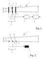
- Fig. 1
- eine schematische Darstellung einer Anordnung von Sensoren am Waffenrohr,
- Fig. 2
- eine schematische Darstellung der Anordnung der Sensoren direkt im Waffenrohr
- Fig. 3
- eine Querschnittdarstellung des Einbaus eines Sensors in das Waffenrohr.
- Fig. 1
- a schematic representation of an arrangement of sensors on the gun barrel,
- Fig. 2
- a schematic representation of the arrangement of the sensors directly in the barrel
- Fig. 3
- a cross-sectional view of the installation of a sensor in the gun barrel.
In Fig. 1 ist schematisch ein Waffenrohr 1 dargestellt, welches hier umfangsseitig wenigstens
zwei Sensoren 2, 3 aufweist. Diese sind vorzugsweise jeweils in einem Trägerring 4, 5 integriert,
welcher zur Aufnahme des jeweiligen Sensors 2, 3 eine Ausnehmung 4.1, 5.1 , hier
eine Bohrung , aufweist. Die Ausnehmungen 4.1, 5.1 können sowohl radial als auch tangential
- oder im Fall von Sensorpaaren radial und tangential - bezüglich der Rohrachse ausgebildet
sein. Die Trägerringe 4, 5 sind vorzugsweise im Bereich der Rohrmündung 6 in
einem definierten Abstand zueinander und von der Mündung angebracht. Einer mit den Sensoren
2, 3 elektrisch verbundene Verstärkerstufe 7 ist eine Signalverarbeitungs- bzw. In Fig. 1, a
Signalauswerteeinheit 8 nachgeschaltet. Auf die Verstärkerstufe 7 kann verzichtet werden,
wenn die Signalgrößen der Sensoren 2, 3 für eine Weiterverarbeitung als ausreichend anzusehen
sind.
Die Sensoren 2, 3 sind derart gestaltet, dass sie in den Bohrungen 4.1, 5.1 passgenau sitzen
und über den Trägerring 4, 5 mechanischen Kontakt zum Waffenrohr 1 besitzen. Die
Trägerringe 4, 5 sind vorzugsweise auf das Waffenrohr 1 aufgeschrumpft. Dazu kann das
Waffenrohr 1 an den vorgesehenen Stellen 9, 10 zylindrisch überdreht werden, an denen
passganau jeweils der zylindrische Trägerring 4, 5 auf diesen zylindrischen Stellen 9, 10
aufgeschrumpft wird. Dadurch erhält die ganze Innenfläche der Trägerringe 4, 5 Kontakt zur
Außenfläche des Waffenrohres 1.
The
In Fig. 2 sind die Sensoren 12, 13 im Waffenrohr 1 direkt eingebunden. Dazu sind in das
Waffenrohr 1 Ausnehmungen 14, 15, vorzugsweise als Bohrungen eingebracht. Die Ausnehmungen
14, 15 können sowohl radial als auch tangential - oder im Fall von Sensorpaaren
radial und tangential - bezüglich der Rohrachse ausgebildet sein. Die Sensoren 12, 13
sind dabei vorzugsweise von außen in die Ausnehmungen 14, 15 eingebracht.In Fig. 2, the
Eine weitere Variante ergibt sich in einer nicht näher dargestellten Ausführung. Dabei weist das Waffenrohr wenigsten zwei voneinander beabstandete Wülste auf, unter bzw. in denen sich die Sensoren befinden. Diese Wülste werden bereits bei der Rohrfertigung ausgeformt und bilden integrale Bestandteile des Waffenrohres, sodass die Ausnehmungen radial oder tangential in die Wülste ausgebildet werden.Another variant results in an embodiment not shown. It points the gun barrel at least two spaced apart beads, under or in which the sensors are located. These beads are already formed during tube production and form integral parts of the barrel, so that the recesses radially or be formed tangentially into the beads.
Eine weitere Möglichkeit nach Fig. 3 besteht darin, den Durchmesser der Rohrinnenwandung
1.1 annähernd voll auszunutzen, wobei die Sensoren 12, ,13 nicht größer als diese Innenwandung
1.1 sein dürfen und nicht in das Waffenrohr 1 hineinragen dürfen. Die Sensoren 12,
13 sind dabei durch einen dünnen Rest der Rohrinnenwandung 14 geschützt, um so nicht
direkt dem Gasdruck ausgesetzt zu werden.Another possibility according to FIG. 3 is the diameter of the tube inner wall
1.1 almost fully exploit, the
Den Sensoren 12, 13 ist wie in Fig. 1 aufgezeigt, zumindest über eine Verstärkerstufe 7 eine
Signalauswerteeinheit 8 nachgeschaltet. Die Auswertung erfolgt je auch hier nach Art und
Nutzung der Messung in bekannter Art und Weise. So wird beispielsweise aus der zeitlichen
Differenz zwischen der Registrierung der Projektilpassage durch die beiden einzelnen Sensoren
die Bewegung und damit die Geschwindigkeit eines nicht näher dargestellten Projektils
ermittelt. As shown in FIG. 1, the
Als Sensoren 2, 3, 12, 13 bieten sich sogenannte Hochtemperatur-Quarz-Längsmessdübel
mit positiver oder negativer Ladungsabgabe an. Diese haben die Fähigkeit in festen Strukturen
Dehnungen dieser Strukturen messen zu können. Die Dehnung der Struktur (Waffenrohr
1 mit Trägerring 4, 5 oder Waffenrohr 1 allein) erfolgt wie folgt: Der vom verbrannten Treibladungspulver
(nicht näher dargestellt) entstehende Gasdruck am Geschossboden des
ebenfalls nicht näher dargestellten Projektils und der Druck des Führungsbandes des Geschosses
auf die Waffenrohrinnenseite dehnt das Waffenrohr 1 beim Geschossdurchgang.
Diese Dehnung wird dem Gehäuse des Längenmessdübels 2, 3, 12, 13 weitergegeben. Der
Quarz im Gehäuse registriert die Dehnung, wodurch eine Ladung erzeugt wird. Das daraus
resultierende Signal wird über die Verstärkerstufe 7 an die Signalauswerteeinheit 8 geführt.As
Claims (4)
Applications Claiming Priority (2)
| Application Number | Priority Date | Filing Date | Title |
|---|---|---|---|
| DE10352047 | 2003-11-07 | ||
| DE10352047A DE10352047A1 (en) | 2003-11-07 | 2003-11-07 | Device for determining the projectile velocity, in particular in the mouth region of a weapon barrel |
Publications (1)
| Publication Number | Publication Date |
|---|---|
| EP1530049A1 true EP1530049A1 (en) | 2005-05-11 |
Family
ID=34428603
Family Applications (1)
| Application Number | Title | Priority Date | Filing Date |
|---|---|---|---|
| EP04026010A Withdrawn EP1530049A1 (en) | 2003-11-07 | 2004-11-03 | Device for measuring the velocity of a projectile, in particular the muzzle velocity |
Country Status (3)
| Country | Link |
|---|---|
| US (1) | US20050115316A1 (en) |
| EP (1) | EP1530049A1 (en) |
| DE (1) | DE10352047A1 (en) |
Cited By (3)
| Publication number | Priority date | Publication date | Assignee | Title |
|---|---|---|---|---|
| RU2448344C1 (en) * | 2010-10-18 | 2012-04-20 | Российская Федерация, от имени которой выступает Государственная корпорация по атомной энергии "Росатом" (Госкорпорация "Росатом") | Method of ammunition trial |
| US20190011208A1 (en) * | 2017-01-13 | 2019-01-10 | Wilcox Industries Corp. | Sensor system for advanced smart weapons barrels |
| CN110470174A (en) * | 2019-08-19 | 2019-11-19 | 哈尔滨工业大学 | The high precision position measuring device and method of class air bubble inertia device test macro |
Families Citing this family (6)
| Publication number | Priority date | Publication date | Assignee | Title |
|---|---|---|---|---|
| DE102006058375A1 (en) * | 2006-12-08 | 2008-06-12 | Oerlikon Contraves Ag | Method for measuring the muzzle velocity of a projectile or the like |
| JP5612579B2 (en) | 2009-07-29 | 2014-10-22 | ギガフォトン株式会社 | Extreme ultraviolet light source device, control method of extreme ultraviolet light source device, and recording medium recording the program |
| US8935963B2 (en) * | 2012-07-30 | 2015-01-20 | The United States Of America As Represented By The Secretary Of The Navy | Gas gun fixture to evaluate blast wave on target sample |
| US11493529B2 (en) * | 2019-05-23 | 2022-11-08 | Hydra Concepts | System for determining muzzle velocity of a firearm |
| CN112505347B (en) * | 2020-12-11 | 2023-06-09 | 西安近代化学研究所 | Viscous flow explosive detonation velocity testing method |
| CN114633899B (en) * | 2022-05-20 | 2022-08-26 | 中国飞机强度研究所 | Combined valve system of air gun for impact power test of aircraft strength test |
Citations (6)
| Publication number | Priority date | Publication date | Assignee | Title |
|---|---|---|---|---|
| FR1390791A (en) * | 1963-04-19 | 1965-02-26 | Ebauches S A Dept Oscilloquart | Device for attaching a measuring base to the muzzle of a weapon |
| US4457206A (en) * | 1979-07-31 | 1984-07-03 | Ares, Inc. | Microwave-type projectile communication apparatus for guns |
| US4955279A (en) * | 1988-09-08 | 1990-09-11 | Rheinmetall Gmbh | Apparatus for setting a projectile time fuze |
| EP0783095A1 (en) * | 1996-01-05 | 1997-07-09 | Olin Corporation | Passive velocity data system |
| EP0840087A1 (en) | 1996-10-30 | 1998-05-06 | THE SECRETARY OF STATE FOR DEFENCE in Her Britannic Majesty's Gvmnt. of the United Kingdom of Great Britain & Northern Ireland | Means for controlling the muzzle velocity of a projectile |
| CH691143A5 (en) | 1995-03-17 | 2001-04-30 | Contraves Ag | Device for measuring shell velocity at mouth of barrel of high cadence weapon has offset magnetic flux sensor coils on closed magnetic circuit perpendicular to barrel |
Family Cites Families (5)
| Publication number | Priority date | Publication date | Assignee | Title |
|---|---|---|---|---|
| US3047766A (en) * | 1960-01-21 | 1962-07-31 | John P Glass | Electronic heading-sensing device |
| US4283989A (en) * | 1979-07-31 | 1981-08-18 | Ares, Inc. | Doppler-type projectile velocity measurement and communication apparatus, and method |
| US4483190A (en) * | 1982-09-24 | 1984-11-20 | Fmc Corporation | Muzzle velocimeter |
| CH680094A5 (en) * | 1990-04-06 | 1992-06-15 | Fischer Ag Georg | |
| CH682515A5 (en) * | 1991-04-22 | 1993-09-30 | Kk Holding Ag | Piezoelectric expansion and force measuring device for machine component - uses sensor housing with two cone rings cooperating with double conical sleeve fitted in wall of component bore |
-
2003
- 2003-11-07 DE DE10352047A patent/DE10352047A1/en not_active Withdrawn
-
2004
- 2004-11-01 US US10/978,900 patent/US20050115316A1/en not_active Abandoned
- 2004-11-03 EP EP04026010A patent/EP1530049A1/en not_active Withdrawn
Patent Citations (6)
| Publication number | Priority date | Publication date | Assignee | Title |
|---|---|---|---|---|
| FR1390791A (en) * | 1963-04-19 | 1965-02-26 | Ebauches S A Dept Oscilloquart | Device for attaching a measuring base to the muzzle of a weapon |
| US4457206A (en) * | 1979-07-31 | 1984-07-03 | Ares, Inc. | Microwave-type projectile communication apparatus for guns |
| US4955279A (en) * | 1988-09-08 | 1990-09-11 | Rheinmetall Gmbh | Apparatus for setting a projectile time fuze |
| CH691143A5 (en) | 1995-03-17 | 2001-04-30 | Contraves Ag | Device for measuring shell velocity at mouth of barrel of high cadence weapon has offset magnetic flux sensor coils on closed magnetic circuit perpendicular to barrel |
| EP0783095A1 (en) * | 1996-01-05 | 1997-07-09 | Olin Corporation | Passive velocity data system |
| EP0840087A1 (en) | 1996-10-30 | 1998-05-06 | THE SECRETARY OF STATE FOR DEFENCE in Her Britannic Majesty's Gvmnt. of the United Kingdom of Great Britain & Northern Ireland | Means for controlling the muzzle velocity of a projectile |
Cited By (4)
| Publication number | Priority date | Publication date | Assignee | Title |
|---|---|---|---|---|
| RU2448344C1 (en) * | 2010-10-18 | 2012-04-20 | Российская Федерация, от имени которой выступает Государственная корпорация по атомной энергии "Росатом" (Госкорпорация "Росатом") | Method of ammunition trial |
| US20190011208A1 (en) * | 2017-01-13 | 2019-01-10 | Wilcox Industries Corp. | Sensor system for advanced smart weapons barrels |
| US10948253B2 (en) * | 2017-01-13 | 2021-03-16 | Wilcox Industries Corp. | Sensor system for advanced smart weapons barrels |
| CN110470174A (en) * | 2019-08-19 | 2019-11-19 | 哈尔滨工业大学 | The high precision position measuring device and method of class air bubble inertia device test macro |
Also Published As
| Publication number | Publication date |
|---|---|
| DE10352047A1 (en) | 2005-06-16 |
| US20050115316A1 (en) | 2005-06-02 |
Similar Documents
| Publication | Publication Date | Title |
|---|---|---|
| EP1530049A1 (en) | Device for measuring the velocity of a projectile, in particular the muzzle velocity | |
| EP2313764B1 (en) | Exhaust gas sensor | |
| EP0108973B1 (en) | Apparatus for measuring the muzzle velocity of a projectile fired by a weapon | |
| DE2733211C3 (en) | Process for the production of a shaped charge projectile from cast explosives and a tool for carrying out the process | |
| DE102006006112B4 (en) | Particle sensor | |
| DE2947937C2 (en) | Method and device for determining roller bearing damage | |
| DE102015109450A1 (en) | Device for measuring the pressure of a fluid flowing through a pipeline | |
| DE102016205495A1 (en) | Measuring device and method for determining layer thickness and associated reference body and calibration body | |
| DE112008001321T5 (en) | Bearing device and device for detecting bearing preloads | |
| CH639774A5 (en) | Appliance for non-destructive testing of ferromagnetic specimens | |
| EP1482311B1 (en) | Device and method for the determination of the muzzle velocity of a projectile | |
| EP0035802B1 (en) | Apparatus for measuring the initial velocity v nill of a projectile fired by a weapon | |
| EP0078334A1 (en) | Calibratable gas turbine motor with interchangeable measuring unit | |
| EP0299282A1 (en) | Method and set-up for testing the functioning of a load suspension device | |
| DE202011105809U1 (en) | Device for measuring the mass flow of a gas | |
| DE1623362B2 (en) | Device for igniting an explosive charge or for triggering a function | |
| DE2745609C2 (en) | Device for measuring flowing media, in particular for determining the amount of a liquid flowing under pressure in a line system | |
| CH682360A5 (en) | ||
| CH691143A5 (en) | Device for measuring shell velocity at mouth of barrel of high cadence weapon has offset magnetic flux sensor coils on closed magnetic circuit perpendicular to barrel | |
| DE102008028711B4 (en) | Method and device for measuring the eccentricity of a hot-finished, seamless tube during manufacture | |
| DE4134589A1 (en) | METHOD FOR DIAGNOSIS OF WEARING MACHINE PARTS | |
| DE102006047549B4 (en) | Igniter for a spin-free projectile | |
| DE2445111C3 (en) | Device for measuring changes in the area of machine parts by inductive means | |
| DE102004007038A1 (en) | Method for monitoring the state of a carbon filter especially for a diesel engine has parts of electrodes near to or on the inner walls of the filter to monitor changes in resistance or impedance | |
| AT5949U1 (en) | PRESSURE MONITOR FOR MEASURING THE PRESSURE IN THE COMBUSTION OF AN INTERNAL COMBUSTION ENGINE |
Legal Events
| Date | Code | Title | Description |
|---|---|---|---|
| PUAI | Public reference made under article 153(3) epc to a published international application that has entered the european phase |
Free format text: ORIGINAL CODE: 0009012 |
|
| 17P | Request for examination filed |
Effective date: 20050115 |
|
| AK | Designated contracting states |
Kind code of ref document: A1 Designated state(s): AT BE BG CH CY CZ DE DK EE ES FI FR GB GR HU IE IS IT LI LU MC NL PL PT RO SE SI SK TR |
|
| AX | Request for extension of the european patent |
Extension state: AL HR LT LV MK YU |
|
| AKX | Designation fees paid |
Designated state(s): AT BE BG CH CY CZ DE DK EE ES FI FR GB GR HU IE IS IT LI LU MC NL PL PT RO SE SI SK TR |
|
| RAP1 | Party data changed (applicant data changed or rights of an application transferred) |
Owner name: RWM SCHWEIZ AG |
|
| 17Q | First examination report despatched |
Effective date: 20061212 |
|
| STAA | Information on the status of an ep patent application or granted ep patent |
Free format text: STATUS: THE APPLICATION HAS BEEN WITHDRAWN |
|
| 18W | Application withdrawn |
Effective date: 20070404 |