EP1530302A2 - Cdma system which uses pre-rotation before transmission - Google Patents
Cdma system which uses pre-rotation before transmission Download PDFInfo
- Publication number
- EP1530302A2 EP1530302A2 EP05002617A EP05002617A EP1530302A2 EP 1530302 A2 EP1530302 A2 EP 1530302A2 EP 05002617 A EP05002617 A EP 05002617A EP 05002617 A EP05002617 A EP 05002617A EP 1530302 A2 EP1530302 A2 EP 1530302A2
- Authority
- EP
- European Patent Office
- Prior art keywords
- signal
- errors
- correction
- base station
- transmission
- Prior art date
- Legal status (The legal status is an assumption and is not a legal conclusion. Google has not performed a legal analysis and makes no representation as to the accuracy of the status listed.)
- Granted
Links
Images


Classifications
-
- H—ELECTRICITY
- H04—ELECTRIC COMMUNICATION TECHNIQUE
- H04B—TRANSMISSION
- H04B1/00—Details of transmission systems, not covered by a single one of groups H04B3/00 - H04B13/00; Details of transmission systems not characterised by the medium used for transmission
- H04B1/69—Spread spectrum techniques
- H04B1/707—Spread spectrum techniques using direct sequence modulation
- H04B1/709—Correlator structure
- H04B1/7093—Matched filter type
-
- H—ELECTRICITY
- H04—ELECTRIC COMMUNICATION TECHNIQUE
- H04L—TRANSMISSION OF DIGITAL INFORMATION, e.g. TELEGRAPHIC COMMUNICATION
- H04L27/00—Modulated-carrier systems
- H04L27/18—Phase-modulated carrier systems, i.e. using phase-shift keying
- H04L27/20—Modulator circuits; Transmitter circuits
-
- H—ELECTRICITY
- H04—ELECTRIC COMMUNICATION TECHNIQUE
- H04B—TRANSMISSION
- H04B1/00—Details of transmission systems, not covered by a single one of groups H04B3/00 - H04B13/00; Details of transmission systems not characterised by the medium used for transmission
- H04B1/62—Details of transmission systems, not covered by a single one of groups H04B3/00 - H04B13/00; Details of transmission systems not characterised by the medium used for transmission for providing a predistortion of the signal in the transmitter and corresponding correction in the receiver, e.g. for improving the signal/noise ratio
-
- H—ELECTRICITY
- H04—ELECTRIC COMMUNICATION TECHNIQUE
- H04B—TRANSMISSION
- H04B1/00—Details of transmission systems, not covered by a single one of groups H04B3/00 - H04B13/00; Details of transmission systems not characterised by the medium used for transmission
- H04B1/69—Spread spectrum techniques
- H04B1/707—Spread spectrum techniques using direct sequence modulation
- H04B1/7097—Interference-related aspects
- H04B1/711—Interference-related aspects the interference being multi-path interference
- H04B1/7115—Constructive combining of multi-path signals, i.e. RAKE receivers
-
- H—ELECTRICITY
- H04—ELECTRIC COMMUNICATION TECHNIQUE
- H04B—TRANSMISSION
- H04B1/00—Details of transmission systems, not covered by a single one of groups H04B3/00 - H04B13/00; Details of transmission systems not characterised by the medium used for transmission
- H04B1/69—Spread spectrum techniques
- H04B1/707—Spread spectrum techniques using direct sequence modulation
- H04B2001/70724—Spread spectrum techniques using direct sequence modulation featuring pilot assisted reception
-
- H—ELECTRICITY
- H04—ELECTRIC COMMUNICATION TECHNIQUE
- H04B—TRANSMISSION
- H04B2201/00—Indexing scheme relating to details of transmission systems not covered by a single group of H04B3/00 - H04B13/00
- H04B2201/69—Orthogonal indexing scheme relating to spread spectrum techniques in general
- H04B2201/696—Orthogonal indexing scheme relating to spread spectrum techniques in general relating to Dowlink
-
- H—ELECTRICITY
- H04—ELECTRIC COMMUNICATION TECHNIQUE
- H04B—TRANSMISSION
- H04B2201/00—Indexing scheme relating to details of transmission systems not covered by a single group of H04B3/00 - H04B13/00
- H04B2201/69—Orthogonal indexing scheme relating to spread spectrum techniques in general
- H04B2201/707—Orthogonal indexing scheme relating to spread spectrum techniques in general relating to direct sequence modulation
- H04B2201/7097—Direct sequence modulation interference
- H04B2201/709709—Methods of preventing interference
-
- H—ELECTRICITY
- H04—ELECTRIC COMMUNICATION TECHNIQUE
- H04L—TRANSMISSION OF DIGITAL INFORMATION, e.g. TELEGRAPHIC COMMUNICATION
- H04L27/00—Modulated-carrier systems
- H04L27/0014—Carrier regulation
- H04L2027/0018—Arrangements at the transmitter end
- H04L2027/0022—Arrangements at the transmitter end using the carrier of the associated receiver of a transceiver
Definitions
- the present invention relates generally to digital communications. More specifically, the invention relates to a system and method for pre-rotating a digital spread spectrum signal prior to transmission in order to improve receiver accuracy and recovery of the phase and frequency information by the receiver.
- CDMA code divisional multiple access
- Shown in Figure 1 is a simplified CDMA communication system that involves a single communication channel of a given bandwidth which is mixed by a spreading code which repeats a predetermined pattern generated by a pseudo-noise (pn) sequence generator.
- a data signal is modulated with the pn sequence to produce digital spread spectrum signal.
- a carrier signal is modulated with the digital spread spectrum signal to establish a forward link and is then transmitted.
- a receiver demodulates the transmission to extract the digital spread spectrum signal. The same process is repeated to establish a reverse link.
- a transmitted signal is typically disturbed by reflections due to varying terrain and environmental conditions and man-made obstructions.
- a single transmitted signal produces a plurality of received signals with differing time delays at the receiver, an effect which is commonly known as multipath distortion.
- multipath distortion the signal from each different path arrives delayed at the receiver with a unique amplitude and carrier phase.
- the error associated with multipath distortion is typically corrected at the receiver after the signal has been correlated with the matching pn sequence and the transmitted data has been reproduced. Thus, the correlation is completed with error incorporated in the signal. Similar multipath distortion affects the reverse link transmission.
- the present invention relates to a digital spread spectrum communication system that calculates phase and frequency error on a received signal from a communicating entity during a wireless communication and pre-corrects a signal for phase and frequency error prior to transmission to that entity.
- Figure 1 is a simplified block diagram of a prior art CDMA communication system.
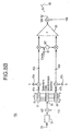
- FIG. 2 is a detailed block diagram of a B-CDMATM communication system.
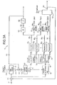
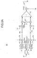
- Figure 3A is a detailed block diagram of the present invention using one pseudo-pilot signal, with carrier-offset correction implemented at the chip level.
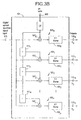
- Figure 3B is a block diagram of a rake receiver.
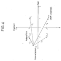
- Figure 4 is a diagram of a received symbol p o on the QP SK constellation showing a hard decision.
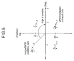
- Figure 5 is a diagram of the angle of correction corresponding to the assigned symbol.
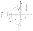
- Figure 6 is a diagram of the resultant symbol error after applying the correction corresponding to the assigned symbol.
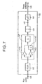
- Figure 7 is a block diagram of a conventional phase-locked loop.
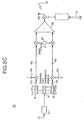
- Figure 8A is a simple block diagram of a transmitter in accordance with the preferred embodiment of the present invention.
- Figure 8B is a simple block diagram of a transmitter in accordance with an alternative embodiment of the present invention.
- Figure 8 C is a simple block diagram of a transmitter in accordance with an alternative embodiment of the present invention.
- a CDMA communication system 25 as shown in Figure 2 includes a transmitter 27 and a receiver 29, which may reside in either a base station or a mobile user receiver.
- the transmitter 27 includes a signal processor 31 which encodes voice and nonvoice signals 33 into data at various rates; e.g. data rates of 8 kbps, 16 kbps, 32 kbps, or 64 kbps.
- the signal processor 31 selects a specific data rate depending upon the type of signal, or in response to a set data rate.
- the input data 33 which can be considered a bi-phase modulated signal is encoded using forward error-correction (FEC) coding 35.
- FEC forward error-correction
- the single bi-phase modulated data signal becomes bivariate or two bi-phase modulated signals.
- One signal is designated the in-phase (I) channel 41 a.
- the other signal is designated the quadrature (Q) channel 41b.
- Bi-phase modulated I and Q signals are usually referred to as quadrature phase shift keying (QPSK).
- the two bi-phase modulated data or symbols 41a, 41b are spread with a complex pseudo-noise (pn) sequence.
- the resulting I 45a and Q 45b spread signals are combined 53 with other spread signals (channels) having different spreading codes, mixed with a carrier signal 51 and then transmitted 55.
- the transmission 55 may contain a plurality of individual channels having different data rates.
- the receiver 29 includes a demodulator 57a, 57b which downconverts the transmitted broadband signal 55 into an intermediate frequency signal 59a, 59b. A second downconversion reduces the signal to baseband.
- the QPSK signal is then filtered 61 and mixed 63a, 63b with the locally generated complex pn sequence 43a, 43b which matches the conjugate of the transmitted complex code. Only the original waveforms which were spread by the same code at the transmitter 27 will be effectively despread. Others will appear as noise to the receiver 29.
- the data 65a, 65b is then passed onto a signal processor 67 where FEC decoding is performed on the convolutionally encoded data.
- the baseband signal When the signal is received and demodulated, the baseband signal is at the chip level. Both the I and Q components of the signal are despread using the conjugate of the pn sequence used during spreading, returning the signal to the symbol level.
- phase corruption experienced during transmission manifests itself by distorting the individual chip waveforms.
- Carrier offset correction may also be performed at the symbol level but with less overall accuracy. However, since the symbol rate is much less than the chip rate, a lower overall processing speed is required when the correction is done at the symbol level.
- a complex baseband digital spread spectrum signal 77 comprised ofin-phase and quadrature phase components is input and filtered using an adaptive matched filter (AMF) 79 or other adaptive filtering means.
- the AMF 79 is a transversal filter (finite impulse response) which uses filter coefficients 81 to overlay delayed replicas of the received signal 77 onto each other to provide a filtered signal output 83 having an increased signal-to-noise ratio (SNR).
- SNR signal-to-noise ratio
- the output 83 of the AMF 79 is coupled to a plurality of channel despreaders 85 1 , 85 2 , 85 n and a pilot despreader 87.
- the pilot signal 89 is despread with a separate despreader 87 and pn sequence 91 contemporaneous with the transmitted data 77 assigned to channels which are despread 85 1 , 85 2 , 85 n with pn sequences 93 1 , 93 2 , 93 n of their own.
- the data bit streams 95 1 , 95 2 , 95 n are coupled to Viterbi decoders 97 1 , 97 2 , 97 n and output 99 1 , 99 2 , 99 n .
- the filter coefficients 81, or weights, used in adjusting the AMF 79 are obtained by the demodulation of the individual multipath propagation paths. This operation is performed by a rake receiver 101.
- the use of a rake receiver 101 to compensate for multipath distortion is well known to those skilled in the communication arts.
- the rake receiver 101 consists of a parallel combination of path demodulators "fingers" 103 0 , 103 1 , 103 2 , 103 n which demodulate a particular multipath component.
- the pilot sequence tracking loop of a particular demodulator is initiated by the timing estimation of a given path as determined by a pn sequence 105.
- a pilot signal is used for despreading the individual signals of the rake.
- the pn sequence 105 may belong to any channel 93 1 of the communication system. Typically, the channel with the largest received signal is used.
- Each path demodulator includes a complex mixer 107 0 , 107 1 ,107 2 ,107 n , and summer and latch 109 0 , 109 1 , 109 2 , 109 n .
- the pn sequence 105 is delayed ⁇ 111 1 , 111 2 , 111 n by one chip and mixed 107 1 , 107 2 , 107 n with the baseband spread spectrum signal 113 thereby despreading each signal.
- Each multiplication product is input into an accumulator 109 0 , 109 1 , 109 2 , 109 n where it is added to the previous product and latched out after the next symbol-clock cycle.
- the rake receiver 101 provides relative path values for each multipath component.
- the plurality of n-dimension outputs 115 0 , 115 1 , 115 2 , 115 n provide estimates of the sampled channel impulse response that contain a relative phase error of either 0°, 90°, 180°, or 270°.
- the plurality of outputs from the rake receiver are coupled to an n-dimensional complex mixer 117.
- Mixed with each rake receiver 101 output 115 is a correction to remove the relative phase error contained in the rake output.
- a pilot signal is also a complex QPSK signal, but with the quadrature component set at zero.
- the error correction 119 signal of the present invention is derived from the despread channel 95 1 by first performing a hard decision 121 on each of the symbols of the despread signal 95 1 .
- a hard decision processor 121 determines the QPSK constellation position that is closest to the despread symbol value.
- the Euclidean distance processor compares a received symbol p o of channel 1 to the four QPSK constellation points x 1 , 1 , x -1, 1 , x -1, -1 , x 1,-1 . It is necessary to examine each received symbol p o due to corruption during transmission 55 by noise and distortion, whether multipath or radio frequency.
- the hard decision processor 121 computes the four distances d 1 , d 2 , d 3 , d 4 to each quadrant from the received symbol p o and chooses the shortest distance d 2 and assigns that symbol location x -1,1 .
- the original symbol coordinates p o are discarded.
- a complex conjugate is one of a pair of complex numbers with identical real parts and with imaginary parts differing only in sign.
- a symbol is demodulated or de-rotated by first determining the complex conjugate of the assigned symbol coordinates x -1,-1 , forming the correction signal 119 which is used to remove the relative phase error contained in the rake output.
- the rake output is effectively de-rotated by the angle associated with the hard decision, removing the relative phase error. This operation effectively provides a rake that is driven by a pilot signal, but without an absolute phase reference.
- the output 119 from the complex conjugate 123 is coupled to a complex n-dimensional mixer 117 where each output of the rake receiver 101 is mixed with the correction signal 119.
- the resulting products 127 are noisy estimates of the channel impulse response p 1 as shown in Figure 6.
- the error shown in Figure 6 is indicated by a radian distance of ⁇ /6 from the in-phase axis.
- the outputs 115 of the complex n-dimensional channel mixer 117 are coupled to an n-dimensional estimator 131.
- the channel estimator 131 is a plurality of low-pass filters, each for filtering a multipath component.
- the outputs 81 of the n-dimensional estimator 131 are coupled to the AMF 79. These outputs 81 act as the AMF 79 filter weights.
- the AMF 79 filters the baseband signal to compensate for channel distortion due to multipath without requiring a large magnitude pilot signal.
- the rake receiver 101 is used in conjunction with the phase-locked loop (PLL) 133 circuits to remove carrier offset.
- Carrier offset occurs as a result of transmitter/receiver component mismatches and other RF distortion.
- the present invention 75 uses a low level pilot signal 135 which is produced by despreading 87 the pilot from the baseband signal 77 with a pilot pn sequence 91.
- the pilot signal is coupled to a single input PLL 133, shown in Figure 7.
- the PLL 133 measures the phase difference between the pilot signal 135 and a reference phase of 0.
- the despread pilot signal 135 is the actual error signal coupled to the PLL 133.
- the PLL 133 includes an arctangent analyzer 136, complex filter 137, an integrator 139 andaphase-to-complex-numberconverter 141.
- the pilot signal 135 is the error signal input to the PLL 133 and is coupled to the complex filter 137.
- the complex filter 137 includes two gain stages, an integrator 145 and a summer 147.
- the output from the complex filter 137 is coupled to the integrator 139.
- the integral of frequency is phase, which is output 140 to the converter 141.
- the phase output 140 is coupled to a converter 141 which converts the phase signal into a complex signal for mixing 151 with the baseband signal 77. Since the upstream operations are commutative, the output 149 of the PLL 133 is also the feedback loop into the system 75.
- the correction signal 119 of the complex conjugate 123 and the output signal 149 of the PLL 133 are each coupled to mixers located within the transmitter 181, in order to correct the signal before transmission as shown in Figure 8A.
- the transmitter 181 shown in Figure 8A operates in a similar manner to the transmitter 27 shown in Figure 2, except that the signal ready for transmission is pre-rotated prior to transmission.
- data 164 1 , 164 2 , 164 3 is encoded using forward correcting coding (FEC) 35.
- FEC forward correcting coding
- the two bi-phase modulated data or symbols 41a, 41b are spread with a complex pseudo-noise (pn) sequence and the resulting I 45a and Q 45b spread signals are mixed with the correction signal 119, upconverted with the carrier signal 51, and combined 53 with other spread signals having different spreading codes.
- the resulting signal 55 is again corrected using the signal 149 from the receiver PLL 133.
- the signal 56 which has been pre-corrected for phase and frequency is then transmitted.
- the present invention utilizes the signals 119, 149 generated by the receiver 71 to pre-correct the transmitted signal and reduce the phase and frequency errors in the signals as received at the receiving unit.
- a transmitter 183 made in accordance with an alternative embodiment of the present invention is shown.
- This embodiment is similar to the embodiment shown in Figure 8A, except that the correction signal 119 is mixed with the baseband data signal via a mixer 157.
- the baseband data is pre-corrected prior to encoding and spreading.
- those of skill in the art should realize that other processing steps may be introduced before the correction signal 119 is mixed with the data signal.
- a transmitter 188 made in accordance with another alternative embodiment of the present invention is shown.
- the correction signal 119 and the carrier offset signal 149 are input into a combiner, which combines the signal into a single pre-correction signal, and mixed using the mixer 169 with the output of the summer 53 prior to transmission.
- the carrier offset correction and the pre-rotation correction are separate corrections. Each may be utilized independently of the other. For example, the system may pre-correct only for carrier offset error and may not perform pre-rotation. Alternatively, the system may perform pre-rotation but may not correct for carrier offset error.
Abstract

Description
- The present invention relates generally to digital communications. More specifically, the invention relates to a system and method for pre-rotating a digital spread spectrum signal prior to transmission in order to improve receiver accuracy and recovery of the phase and frequency information by the receiver.
- Many current communication systems use digital spread spectrum modulation or code divisional multiple access (CDMA) technology. Digital spread spectrum is a communication technique in which data is transmitted with a broadened band (spread spectrum) by modulating the data to be transmitted with a pseudo-noise signal. CDMA can transmit data without being affected by signal distortion or an interfering frequency in the transmission path.
- Shown in Figure 1 is a simplified CDMA communication system that involves a single communication channel of a given bandwidth which is mixed by a spreading code which repeats a predetermined pattern generated by a pseudo-noise (pn) sequence generator. A data signal is modulated with the pn sequence to produce digital spread spectrum signal. A carrier signal is modulated with the digital spread spectrum signal to establish a forward link and is then transmitted. A receiver demodulates the transmission to extract the digital spread spectrum signal. The same process is repeated to establish a reverse link.
- During terrestrial communication, a transmitted signal is typically disturbed by reflections due to varying terrain and environmental conditions and man-made obstructions. Thus, a single transmitted signal produces a plurality of received signals with differing time delays at the receiver, an effect which is commonly known as multipath distortion. During multipath distortion, the signal from each different path arrives delayed at the receiver with a unique amplitude and carrier phase.
- In the prior art, the error associated with multipath distortion is typically corrected at the receiver after the signal has been correlated with the matching pn sequence and the transmitted data has been reproduced. Thus, the correlation is completed with error incorporated in the signal. Similar multipath distortion affects the reverse link transmission.
- Accordingly, there exists a need for a system that corrects a signal for errors encountered during transmission.
- The present invention relates to a digital spread spectrum communication system that calculates phase and frequency error on a received signal from a communicating entity during a wireless communication and pre-corrects a signal for phase and frequency error prior to transmission to that entity.
- Figure 1 is a simplified block diagram of a prior art CDMA communication system.
- Figure 2 is a detailed block diagram of a B-CDMA™ communication system.
- Figure 3A is a detailed block diagram of the present invention using one pseudo-pilot signal, with carrier-offset correction implemented at the chip level.
- Figure 3B is a block diagram of a rake receiver.
- Figure 4 is a diagram of a received symbol po on the QP SK constellation showing a hard decision.
- Figure 5 is a diagram of the angle of correction corresponding to the assigned symbol.
- Figure 6 is a diagram of the resultant symbol error after applying the correction corresponding to the assigned symbol.
- Figure 7 is a block diagram of a conventional phase-locked loop.
- Figure 8A is a simple block diagram of a transmitter in accordance with the preferred embodiment of the present invention.
- Figure 8B is a simple block diagram of a transmitter in accordance with an alternative embodiment of the present invention.
- Figure 8 C is a simple block diagram of a transmitter in accordance with an alternative embodiment of the present invention.
- The preferred embodiment will be described with reference to the drawing figures where like numerals represent like elements throughout.
- A
CDMA communication system 25 as shown in Figure 2 includes atransmitter 27 and areceiver 29, which may reside in either a base station or a mobile user receiver. Thetransmitter 27 includes asignal processor 31 which encodes voice and nonvoice signals 33 into data at various rates; e.g. data rates of 8 kbps, 16 kbps, 32 kbps, or 64 kbps. Thesignal processor 31 selects a specific data rate depending upon the type of signal, or in response to a set data rate. - By way of background, two steps are involved in the generation of a transmitted signal in a multiple access environment. First, the
input data 33 which can be considered a bi-phase modulated signal is encoded using forward error-correction (FEC)coding 35. For example, if a R=½ convolution code is used, the single bi-phase modulated data signal becomes bivariate or two bi-phase modulated signals. One signal is designated the in-phase (I)channel 41 a. The other signal is designated the quadrature (Q)channel 41b. A complex number is in the form a+bj, where a and b are real numbers and j2=-1. Bi-phase modulated I and Q signals are usually referred to as quadrature phase shift keying (QPSK). In the preferred embodiment, the tap generator polynomials for a constraint length of K=7 and a convolutional code rate of R=½ are G1=1718 37 and G2=1338 39. - In the second step, the two bi-phase modulated data or
symbols I 45a andQ 45b spread signals are combined 53 with other spread signals (channels) having different spreading codes, mixed with acarrier signal 51 and then transmitted 55. Thetransmission 55 may contain a plurality of individual channels having different data rates. - The
receiver 29 includes ademodulator broadband signal 55 into anintermediate frequency signal complex pn sequence transmitter 27 will be effectively despread. Others will appear as noise to thereceiver 29. Thedata signal processor 67 where FEC decoding is performed on the convolutionally encoded data. - When the signal is received and demodulated, the baseband signal is at the chip level. Both the I and Q components of the signal are despread using the conjugate of the pn sequence used during spreading, returning the signal to the symbol level. However, due to carrier offset, phase corruption experienced during transmission manifests itself by distorting the individual chip waveforms. If carrier offset correction is performed at the chip level overall accuracy increases due to the inherent resolution of the chip-level signal. Carrier offset correction may also be performed at the symbol level but with less overall accuracy. However, since the symbol rate is much less than the chip rate, a lower overall processing speed is required when the correction is done at the symbol level.
- As shown in Figure 3A, a receiver using the
system 75 and method of the present invention is shown. A complex baseband digitalspread spectrum signal 77 comprised ofin-phase and quadrature phase components is input and filtered using an adaptive matched filter (AMF) 79 or other adaptive filtering means. The AMF 79 is a transversal filter (finite impulse response) which usesfilter coefficients 81 to overlay delayed replicas of the receivedsignal 77 onto each other to provide a filteredsignal output 83 having an increased signal-to-noise ratio (SNR). Theoutput 83 of the AMF 79 is coupled to a plurality of channel despreaders 851, 852, 85n and apilot despreader 87. The pilot signal 89 is despread with aseparate despreader 87 andpn sequence 91 contemporaneous with the transmitteddata 77 assigned to channels which are despread 851, 852, 85n withpn sequences output - The filter coefficients 81, or weights, used in adjusting the
AMF 79 are obtained by the demodulation of the individual multipath propagation paths. This operation is performed by arake receiver 101. The use of arake receiver 101 to compensate for multipath distortion is well known to those skilled in the communication arts. - As shown in Figure 3B, the
rake receiver 101 consists of a parallel combination of path demodulators "fingers" 1030, 1031, 1032, 103n which demodulate a particular multipath component. The pilot sequence tracking loop of a particular demodulator is initiated by the timing estimation of a given path as determined by a pn sequence 105. In the prior art, a pilot signal is used for despreading the individual signals of the rake. In the present invention, the pn sequence 105 may belong to anychannel 931 of the communication system. Typically, the channel with the largest received signal is used. - Each path demodulator includes a
complex mixer accumulator rake receiver 101 provides relative path values for each multipath component. The plurality of n-dimension outputs - Referring back to Figure 3A, the plurality of outputs from the rake receiver are coupled to an n-dimensional
complex mixer 117. Mixed with eachrake receiver 101output 115 is a correction to remove the relative phase error contained in the rake output. - A pilot signal is also a complex QPSK signal, but with the quadrature component set at zero. The
error correction 119 signal of the present invention is derived from the despread channel 951 by first performing ahard decision 121 on each of the symbols of the despread signal 951. Ahard decision processor 121 determines the QPSK constellation position that is closest to the despread symbol value. - As shown in Figure 4, the Euclidean distance processor compares a received symbol po of
channel 1 to the four QPSK constellation points x1, 1, x-1, 1, x-1, -1, x1,-1. It is necessary to examine each received symbol po due to corruption duringtransmission 55 by noise and distortion, whether multipath or radio frequency. Thehard decision processor 121 computes the four distances d1, d2, d3, d4 to each quadrant from the received symbol po and chooses the shortest distance d2 and assigns that symbol location x-1,1. The original symbol coordinates po are discarded. - Referring back to Figure 3A, after undergoing each
hard symbol decision 121, thecomplex conjugates 123 for eachsymbol output 125 are determined. A complex conjugate is one of a pair of complex numbers with identical real parts and with imaginary parts differing only in sign. As shown in Figure 5, a symbol is demodulated or de-rotated by first determining the complex conjugate of the assigned symbol coordinates x-1,-1, forming thecorrection signal 119 which is used to remove the relative phase error contained in the rake output. Thus, the rake output is effectively de-rotated by the angle associated with the hard decision, removing the relative phase error. This operation effectively provides a rake that is driven by a pilot signal, but without an absolute phase reference. - Referring back to Figure 3A, the
output 119 from thecomplex conjugate 123 is coupled to a complex n-dimensional mixer 117 where each output of therake receiver 101 is mixed with thecorrection signal 119. The resulting products 127 are noisy estimates of the channel impulse response p1 as shown in Figure 6. The error shown in Figure 6 is indicated by a radian distance of π/6 from the in-phase axis. - Referring back to Figure 3A, the
outputs 115 of the complex n-dimensional channel mixer 117 are coupled to an n-dimensional estimator 131. Thechannel estimator 131 is a plurality of low-pass filters, each for filtering a multipath component. Theoutputs 81 of the n-dimensional estimator 131 are coupled to theAMF 79. Theseoutputs 81 act as theAMF 79 filter weights. TheAMF 79 filters the baseband signal to compensate for channel distortion due to multipath without requiring a large magnitude pilot signal. - The
rake receiver 101 is used in conjunction with the phase-locked loop (PLL) 133 circuits to remove carrier offset. Carrier offset occurs as a result of transmitter/receiver component mismatches and other RF distortion. Thepresent invention 75 uses a lowlevel pilot signal 135 which is produced by despreading 87 the pilot from the baseband signal 77 with apilot pn sequence 91. The pilot signal is coupled to asingle input PLL 133, shown in Figure 7. ThePLL 133 measures the phase difference between thepilot signal 135 and a reference phase of 0. Thedespread pilot signal 135 is the actual error signal coupled to thePLL 133. - The
PLL 133 includes anarctangent analyzer 136, complex filter 137, anintegrator 139 andaphase-to-complex-numberconverter 141. Thepilot signal 135 is the error signal input to thePLL 133 and is coupled to the complex filter 137. The complex filter 137 includes two gain stages, anintegrator 145 and asummer 147. The output from the complex filter 137 is coupled to theintegrator 139. The integral of frequency is phase, which isoutput 140 to theconverter 141. Thephase output 140 is coupled to aconverter 141 which converts the phase signal into a complex signal for mixing 151 with thebaseband signal 77. Since the upstream operations are commutative, theoutput 149 of thePLL 133 is also the feedback loop into thesystem 75. - The
correction signal 119 of thecomplex conjugate 123 and theoutput signal 149 of thePLL 133 are each coupled to mixers located within thetransmitter 181, in order to correct the signal before transmission as shown in Figure 8A. Thetransmitter 181 shown in Figure 8A operates in a similar manner to thetransmitter 27 shown in Figure 2, except that the signal ready for transmission is pre-rotated prior to transmission. Referring to Figure 8A, data 1641, 1642, 1643 is encoded using forward correcting coding (FEC) 35. The two bi-phase modulated data orsymbols I 45a andQ 45b spread signals are mixed with thecorrection signal 119, upconverted with thecarrier signal 51, and combined 53 with other spread signals having different spreading codes. The resultingsignal 55 is again corrected using thesignal 149 from thereceiver PLL 133. The signal 56 which has been pre-corrected for phase and frequency is then transmitted. In this manner, the present invention utilizes thesignals - Referring to Figure 8B, a
transmitter 183 made in accordance with an alternative embodiment of the present invention is shown. This embodiment is similar to the embodiment shown in Figure 8A, except that thecorrection signal 119 is mixed with the baseband data signal via amixer 157. Thus, the baseband data is pre-corrected prior to encoding and spreading. Of course, those of skill in the art should realize that other processing steps may be introduced before thecorrection signal 119 is mixed with the data signal. - Referring to Figure 8C, a
transmitter 188 made in accordance with another alternative embodiment of the present invention is shown. In this embodiment, thecorrection signal 119 and the carrier offsetsignal 149 are input into a combiner, which combines the signal into a single pre-correction signal, and mixed using themixer 169 with the output of thesummer 53 prior to transmission. - Finally, it should be noted that the carrier offset correction and the pre-rotation correction are separate corrections. Each may be utilized independently of the other. For example, the system may pre-correct only for carrier offset error and may not perform pre-rotation. Alternatively, the system may perform pre-rotation but may not correct for carrier offset error.
- While specific embodiments of the present invention have been shown and described, many modifications and variations could be made by one skilled in the art without departing from the spirit and scope of the invention. The above description serves to illustrate and not limit the particular form in any way.
- Preferred Aspects of the Invention:
- 1. A method for reducing transmission errors in a CDMA communication
system having at least two communication units, comprising:
- receiving at a first communication unit a CDMA communication signal sent from a second communication unit;
- analyzing said received signal for phase errors;
- correcting said received signal with a collection signal based upon said analysis;
- using said correction signal to pie-rotate a signal prior to transmission from said first communication unit to said second communication unit.
- 2. A method for reducing transmission errors in a CDMA communication
system having at least two communication units, comprising:
- receiving at a first communication unit a CDMA communication signal sent from a second communication unit;
- analyzing said received signal for errors;
- generating a correction signal based upon said analysis; and
- correcting an information signal, including voice or data, with said correction signal prior to transmission of said information signal from said first communication unit to said second communication unit.
- 3. The method of
aspect 2 wherein said errors include phase errors and said collection signal collects for said phase errors. - 4. The method of
aspect 2 wherein said errors include frequency errors and said collection signal corrects for said frequency errors. - 5. A COMA communication system for reducing transmission errors
during communications between at least two communication units, each
communication unit comprising:
- a receiver for receiving a CDMA communication signal sent from another communication unit;
- an analyzer for analyzing said received signal for errors and for generating a correction signal; and
- a correction unit correcting said received signal with a correction signal based upon said analysis;
- a transmitter for using said correction signal to pre-correct a signal prior to transmission to another communication unit.
- 6. A communication station of a CDMA system having a plurality of
communication stations which communicate with each other over a CDMA air
interface using a plurality of channels and a pilot signal for carrier1 offset recovery
during reception; each communication station including a receiver and a transmitter;
the receiving comprising: - an adaptive matched filter for receiving demodulated CDMA communication signals producing a filtered signal by using a weighting signal;
- a rake receiver for receiving demodulated CDMA communication signals and a pseudo-noise signal generated for a selected channel and producing a filter weighting signal;
- means for the filter weighting signal with a correction signal, said correction signal for producing the weighting signal used by said adaptive matched filter;
- at least one despreader coupled to said adaptive matched filter output for
despreading said filtered signal using the pseudo-noise signal generator for said
selected channel to produce a despread signal; and the transmitter comprising:
- a data input for providing an information signal; at least one spreader for spreading said information signal; a mixer for mixing the spread signal with said correction signal prior to upconversion and transmission;
- whereby a transmitted signal is pre-corrected with said correction signal prior to transmission.
-
Claims (11)
- A method for reducing transmission errors by a base station when transmitting a communication signal, comprising the steps of:receiving an RF communication signal at said base station;analyzing said received signal for errors;generating a correction signal based upon said analysis; andcorrecting said communication signal using said correction signal prior to transmission of said communication signal from said base station.
- The method of claim 1 further comprising the step of:filtering said received signal to generate a filtered signal using a weighting signal;demodulating said received signal to generate relative path values for each multipath component in said received signal; andmixing said path values with said correction signal to generate said weighting signal.
- The method of claim 1 wherein said errors include phase errors and said correction signal corrects for said phase errors prior to transmission of said communication signal.
- The method of claim 1 wherein said errors include frequency errors and said correction signal corrects for said frequency errors prior to transmission of said communication signal.
- The method of claim 2 wherein said analyzing step includes:wherein said correction signal removes relative phase errors contained in the path values.despreading said filtered signal using a pilot signal;performing a hard decision on said despread filtered signal to generate symbol outputs; anddetermining the complex conjugates of said symbol outputs to generate said correction signal;
- A base station for transmitting and receiving communication signals comprising a receiver and transmitter for reducing transmission errors in said transmitted signal, the receiver including:an antenna for receiving a communication signal;an analyzer for analyzing said received signal for errors and generating a correction signal based on said analysis; anda correction unit for correcting said received signal using said correction signal; andsaid transmitter responsive to said correction unit, for correcting said transmitted signal prior to transmission.
- The base station of claim 6 wherein said receiver further includes an adaptive matched filter for filtering said received signal to generate a filtered signal using a weighting signal.
- The base station of claim 7 wherein said analyzer includes:at least one despreader for despreading said filtered signal using a pilot signal; a processor for performing a hard decision on said despread filtered signal andgenerating symbol outputs therefrom; anda conjugator for determining the complex conjugates of said symbol outputs to generate said correction signal
- The base station of claim 8 wherein said correction unit comprises:a RAKE receiver for demodulating said received signal and generating relative path values for each multipath component of said received signal; anda mixer for mixing said path values with said correction signal to generate said weighting signal.
- The base station of claim 6 wherein said errors include phase errors and said correction signal corrects for said phase errors prior to transmission of said communication signal.
- The base station of claim 6 wherein said errors include frequency errors and said correction signal corrects for said frequency errors prior to transmission of said communication signal.
Priority Applications (1)
| Application Number | Priority Date | Filing Date | Title |
|---|---|---|---|
| EP07023689A EP1901441A1 (en) | 2000-03-28 | 2001-03-28 | CDMA system which uses pre-rotation before transmission |
Applications Claiming Priority (3)
| Application Number | Priority Date | Filing Date | Title |
|---|---|---|---|
| US19267000P | 2000-03-28 | 2000-03-28 | |
| US192670P | 2000-03-28 | ||
| EP01922797A EP1279238B1 (en) | 2000-03-28 | 2001-03-28 | Cdma system which uses pre-rotation before transmission |
Related Parent Applications (1)
| Application Number | Title | Priority Date | Filing Date |
|---|---|---|---|
| EP01922797A Division EP1279238B1 (en) | 2000-03-28 | 2001-03-28 | Cdma system which uses pre-rotation before transmission |
Related Child Applications (1)
| Application Number | Title | Priority Date | Filing Date |
|---|---|---|---|
| EP07023689A Division EP1901441A1 (en) | 2000-03-28 | 2001-03-28 | CDMA system which uses pre-rotation before transmission |
Publications (3)
| Publication Number | Publication Date |
|---|---|
| EP1530302A2 true EP1530302A2 (en) | 2005-05-11 |
| EP1530302A3 EP1530302A3 (en) | 2005-08-03 |
| EP1530302B1 EP1530302B1 (en) | 2008-01-23 |
Family
ID=22710585
Family Applications (5)
| Application Number | Title | Priority Date | Filing Date |
|---|---|---|---|
| EP10004181A Withdrawn EP2230773A1 (en) | 2000-03-28 | 2001-03-28 | Cdma system which uses pre-rotation before transmission |
| EP07023689A Withdrawn EP1901441A1 (en) | 2000-03-28 | 2001-03-28 | CDMA system which uses pre-rotation before transmission |
| EP05002616A Expired - Lifetime EP1530301B1 (en) | 2000-03-28 | 2001-03-28 | Cdma system which uses pre-rotation before transmission |
| EP01922797A Expired - Lifetime EP1279238B1 (en) | 2000-03-28 | 2001-03-28 | Cdma system which uses pre-rotation before transmission |
| EP05002617A Expired - Lifetime EP1530302B1 (en) | 2000-03-28 | 2001-03-28 | Cdma system which uses pre-rotation before transmission |
Family Applications Before (4)
| Application Number | Title | Priority Date | Filing Date |
|---|---|---|---|
| EP10004181A Withdrawn EP2230773A1 (en) | 2000-03-28 | 2001-03-28 | Cdma system which uses pre-rotation before transmission |
| EP07023689A Withdrawn EP1901441A1 (en) | 2000-03-28 | 2001-03-28 | CDMA system which uses pre-rotation before transmission |
| EP05002616A Expired - Lifetime EP1530301B1 (en) | 2000-03-28 | 2001-03-28 | Cdma system which uses pre-rotation before transmission |
| EP01922797A Expired - Lifetime EP1279238B1 (en) | 2000-03-28 | 2001-03-28 | Cdma system which uses pre-rotation before transmission |
Country Status (17)
| Country | Link |
|---|---|
| US (10) | US6831941B2 (en) |
| EP (5) | EP2230773A1 (en) |
| JP (6) | JP4094852B2 (en) |
| KR (9) | KR20090123970A (en) |
| CN (2) | CN1707991B (en) |
| AT (3) | ATE289135T1 (en) |
| AU (4) | AU4955801A (en) |
| BR (1) | BR0109904A (en) |
| CA (2) | CA2652083A1 (en) |
| DE (3) | DE60132643T2 (en) |
| DK (3) | DK1279238T3 (en) |
| ES (3) | ES2236210T3 (en) |
| HK (1) | HK1057429A1 (en) |
| IL (3) | IL151905A0 (en) |
| MX (1) | MXPA02009345A (en) |
| NO (2) | NO326188B1 (en) |
| WO (1) | WO2001073968A1 (en) |
Families Citing this family (26)
| Publication number | Priority date | Publication date | Assignee | Title |
|---|---|---|---|---|
| US6366607B1 (en) * | 1998-05-14 | 2002-04-02 | Interdigital Technology Corporation | Processing for improved performance and reduced pilot |
| EP2230773A1 (en) | 2000-03-28 | 2010-09-22 | InterDigital Technology Corporation | Cdma system which uses pre-rotation before transmission |
| WO2003047281A1 (en) * | 2001-11-26 | 2003-06-05 | Nokia Corporation | Mac layer inverse multiplexing in a third generation ran |
| MXPA04008840A (en) * | 2002-03-19 | 2004-11-26 | Thomson Licensing Sa | Slicing algorithm for multi-level modulation equalizing schemes. |
| KR100640581B1 (en) | 2004-07-02 | 2006-10-31 | 삼성전자주식회사 | OFDMA system and method for controlling frequency offsets of subscribers at uplink communication |
| DE102004038621B3 (en) * | 2004-08-09 | 2006-02-16 | Siemens Ag | Determination procedure for a position signal |
| JP4351658B2 (en) * | 2005-07-21 | 2009-10-28 | マイクロン テクノロジー, インク. | Memory capacity reduction method, memory capacity reduction noise reduction circuit, and memory capacity reduction device |
| JP4699843B2 (en) * | 2005-09-15 | 2011-06-15 | 富士通株式会社 | Mobile communication system, and base station apparatus and mobile station apparatus used in mobile communication system |
| KR101084779B1 (en) * | 2006-11-06 | 2011-11-21 | 콸콤 인코포레이티드 | Methods and apparatus for codeword level scrambling for mimo transmission |
| US7593452B1 (en) * | 2008-03-18 | 2009-09-22 | On-Ramp Wireless, Inc. | Despreading spread spectrum data |
| US20090239550A1 (en) * | 2008-03-18 | 2009-09-24 | Myers Theodore J | Random phase multiple access system with location tracking |
| US7733945B2 (en) * | 2008-03-18 | 2010-06-08 | On-Ramp Wireless, Inc. | Spread spectrum with doppler optimization |
| US7773664B2 (en) * | 2008-03-18 | 2010-08-10 | On-Ramp Wireless, Inc. | Random phase multiple access system with meshing |
| US8520721B2 (en) | 2008-03-18 | 2013-08-27 | On-Ramp Wireless, Inc. | RSSI measurement mechanism in the presence of pulsed jammers |
| US8958460B2 (en) | 2008-03-18 | 2015-02-17 | On-Ramp Wireless, Inc. | Forward error correction media access control system |
| US8477830B2 (en) | 2008-03-18 | 2013-07-02 | On-Ramp Wireless, Inc. | Light monitoring system using a random phase multiple access system |
| US8995568B1 (en) | 2008-09-05 | 2015-03-31 | Marvell International Ltd. | Phase transformation of repeated signals |
| US7639726B1 (en) * | 2009-03-20 | 2009-12-29 | On-Ramp Wireless, Inc. | Downlink communication |
| US8363699B2 (en) | 2009-03-20 | 2013-01-29 | On-Ramp Wireless, Inc. | Random timing offset determination |
| US7702290B1 (en) | 2009-04-08 | 2010-04-20 | On-Ramp Wirless, Inc. | Dynamic energy control |
| US20120265872A1 (en) * | 2011-04-18 | 2012-10-18 | Cox Communications, Inc. | Systems and Methods of Automatically Remediating Fault Conditions |
| US9166839B2 (en) | 2013-02-13 | 2015-10-20 | Aviat U.S., Inc. | Systems and methods for reducing effects of local oscillator leakage |
| JP2016167781A (en) * | 2015-03-10 | 2016-09-15 | 富士通株式会社 | Radio communication device and method of controlling radio communication device |
| US9729119B1 (en) | 2016-03-04 | 2017-08-08 | Atmel Corporation | Automatic gain control for received signal strength indication |
| KR102327767B1 (en) * | 2016-11-08 | 2021-11-17 | 프라운호퍼-게젤샤프트 추르 푀르데룽 데어 안제반텐 포르슝 에 파우 | Apparatus and method for downmixing or upmixing multi-channel signals using phase compensation |
| CN106685473B (en) * | 2016-12-22 | 2018-03-02 | 惠科股份有限公司 | Spread spectrum coding/decoding method, terminal and the display device of a kind of transmission signal |
Citations (6)
| Publication number | Priority date | Publication date | Assignee | Title |
|---|---|---|---|---|
| US5351016A (en) * | 1993-05-28 | 1994-09-27 | Ericsson Ge Mobile Communications Inc. | Adaptively self-correcting modulation system and method |
| US5499236A (en) * | 1994-08-16 | 1996-03-12 | Unisys Corporation | Synchronous multipoint-to-point CDMA communication system |
| US5659573A (en) * | 1994-10-04 | 1997-08-19 | Motorola, Inc. | Method and apparatus for coherent reception in a spread-spectrum receiver |
| EP0818892A2 (en) * | 1996-07-09 | 1998-01-14 | Hitachi, Ltd. | Synchronisation of the reverse link in a CDMA communications system |
| US5794119A (en) * | 1995-11-21 | 1998-08-11 | Stanford Telecommunications, Inc. | Subscriber frequency control system and method in point-to-multipoint RF communication system |
| FR2767238A1 (en) * | 1997-08-07 | 1999-02-12 | Alsthom Cge Alcatel | SINGLE-CHANNEL AND MULTI-CHANNEL DEVICES FOR CONSISTENT DEMODULATION WITHOUT A PILOT, AND CORRESPONDING RECEIVING ASSEMBLY FOR MULTIPLE DIVERSITY PATHS |
Family Cites Families (43)
| Publication number | Priority date | Publication date | Assignee | Title |
|---|---|---|---|---|
| JPS51116609A (en) * | 1975-04-04 | 1976-10-14 | Nec Corp | Initial connection system and apparatus for time division multiple acc ess communication system |
| US4328585A (en) * | 1980-04-02 | 1982-05-04 | Signatron, Inc. | Fast adapting fading channel equalizer |
| EP0064996B1 (en) * | 1980-11-19 | 1985-10-30 | Ford Motor Company Limited | Motor vehicle wheel suspension |
| GB2135844B (en) * | 1983-02-21 | 1986-08-28 | Nippon Telegraph & Telephone | Oscillator with variable frequency and phase |
| KR950001519B1 (en) * | 1991-12-17 | 1995-02-25 | 주식회사금성사 | Qpsk demodulation circuit of nicam receiver |
| US5579338A (en) | 1992-06-29 | 1996-11-26 | Mitsubishi Denki Kabushiki Kaisha | Spread spectrum receiver using partial correlations |
| JP2919204B2 (en) | 1992-11-16 | 1999-07-12 | エヌ・ティ・ティ移動通信網株式会社 | Transceiver |
| US5305349A (en) * | 1993-04-29 | 1994-04-19 | Ericsson Ge Mobile Communications Inc. | Quantized coherent rake receiver |
| CN1035586C (en) | 1993-10-13 | 1997-08-06 | Ntt移动通信网株式会社 | Receiver for spread spectrum communication |
| EP0688483B1 (en) * | 1993-12-03 | 2001-04-04 | Koninklijke Philips Electronics N.V. | A digital communication system and a receiver for use in such a system |
| US5694388A (en) | 1994-06-23 | 1997-12-02 | Ntt Mobile Communications Network Inc. | CDMA demodulator and demodulation method |
| CA2153516C (en) * | 1994-07-20 | 1999-06-01 | Yasuo Ohgoshi | Mobile station for cdma mobile communication system and detection method of the same |
| US5619524A (en) | 1994-10-04 | 1997-04-08 | Motorola, Inc. | Method and apparatus for coherent communication reception in a spread-spectrum communication system |
| JPH08172464A (en) | 1994-12-20 | 1996-07-02 | Fujitsu Ltd | Carrier phase control circuit |
| KR0144828B1 (en) * | 1994-12-23 | 1998-08-01 | 양승택 | Qpsk demodulator |
| US5691974A (en) | 1995-01-04 | 1997-11-25 | Qualcomm Incorporated | Method and apparatus for using full spectrum transmitted power in a spread spectrum communication system for tracking individual recipient phase, time and energy |
| ZA965340B (en) * | 1995-06-30 | 1997-01-27 | Interdigital Tech Corp | Code division multiple access (cdma) communication system |
| JPH0969798A (en) | 1995-09-01 | 1997-03-11 | Toshiba Corp | Portable radio machine and radio communication system using this machine |
| JP3200547B2 (en) * | 1995-09-11 | 2001-08-20 | 株式会社日立製作所 | CDMA mobile communication system |
| JP3070825B2 (en) | 1995-10-04 | 2000-07-31 | 松下電器産業株式会社 | Mobile communication device |
| JP2850949B2 (en) | 1995-12-15 | 1999-01-27 | 日本電気株式会社 | Digital PLL device |
| US5930288A (en) | 1996-05-06 | 1999-07-27 | Motorola, Inc. | Time-shared lock indicator circuit and method for power control and traffic channel decoding in a radio receiver |
| US5901173A (en) * | 1996-12-09 | 1999-05-04 | Raytheon Company | Noise Estimator |
| JP3311951B2 (en) * | 1996-12-20 | 2002-08-05 | 富士通株式会社 | Code multiplex transmitter |
| KR100407916B1 (en) | 1996-12-27 | 2004-03-24 | 엘지전자 주식회사 | Qpsk demodulator |
| US6055231A (en) * | 1997-03-12 | 2000-04-25 | Interdigital Technology Corporation | Continuously adjusted-bandwidth discrete-time phase-locked loop |
| JP3204925B2 (en) * | 1997-06-18 | 2001-09-04 | 株式会社エヌ・ティ・ティ・ドコモ | Signal receiving apparatus in CDMA communication system |
| JPH11186987A (en) * | 1997-12-22 | 1999-07-09 | Matsushita Electric Ind Co Ltd | Phase tracking device for cdma receiver |
| JPH11252614A (en) * | 1998-03-05 | 1999-09-17 | Kokusai Electric Co Ltd | Communication system, base station device and mobile station device |
| US6366607B1 (en) * | 1998-05-14 | 2002-04-02 | Interdigital Technology Corporation | Processing for improved performance and reduced pilot |
| US6452948B1 (en) * | 1998-06-10 | 2002-09-17 | Sicom, Inc. | Method for baud-clock phase synchronization in a TDMA digital communications system and apparatus therefor |
| US6181674B1 (en) * | 1998-09-30 | 2001-01-30 | Conexant Systems, Inc. | Method and apparatus for sharing transmit shaping filters among phase shifted signals |
| US6364296B1 (en) * | 1998-11-24 | 2002-04-02 | Freudenberg-Nok General Partnership | Shear mount |
| US6366604B1 (en) * | 1998-12-18 | 2002-04-02 | Philips Electric North America Corporation | Compensation for phase errors caused by clock jitter in a CDMA communication system |
| JP3362009B2 (en) * | 1999-03-01 | 2003-01-07 | シャープ株式会社 | Spread spectrum communication equipment |
| ES2178364T3 (en) * | 1999-06-24 | 2002-12-16 | Cit Alcatel | DIVERSITY TRANSMISSION IN A MOBILE RADIO SYSTEM. |
| US6963602B1 (en) * | 2000-01-05 | 2005-11-08 | Advanced Micro Devices, Inc. | Digital correction method and system |
| JP4495288B2 (en) * | 2000-01-18 | 2010-06-30 | パナソニック株式会社 | Base station apparatus, communication terminal apparatus, and wireless communication method |
| EP2230773A1 (en) * | 2000-03-28 | 2010-09-22 | InterDigital Technology Corporation | Cdma system which uses pre-rotation before transmission |
| DE60124234T2 (en) * | 2000-04-04 | 2007-09-13 | Broadcom Corp., Irvine | METHOD FOR COMPENSATING PHASE ERRORS IN MULTIPLE SIGNALS |
| JP4253445B2 (en) * | 2001-03-16 | 2009-04-15 | 富士通株式会社 | Deviation compensation device |
| US7242722B2 (en) * | 2003-10-17 | 2007-07-10 | Motorola, Inc. | Method and apparatus for transmission and reception within an OFDM communication system |
| US7804912B2 (en) * | 2004-09-23 | 2010-09-28 | Motorola, Inc. | Method and apparatus for encryption of over-the-air communications in a wireless communication system |
-
2001
- 2001-03-28 EP EP10004181A patent/EP2230773A1/en not_active Withdrawn
- 2001-03-28 EP EP07023689A patent/EP1901441A1/en not_active Withdrawn
- 2001-03-28 ES ES01922797T patent/ES2236210T3/en not_active Expired - Lifetime
- 2001-03-28 AT AT01922797T patent/ATE289135T1/en not_active IP Right Cessation
- 2001-03-28 JP JP2001571572A patent/JP4094852B2/en not_active Expired - Fee Related
- 2001-03-28 EP EP05002616A patent/EP1530301B1/en not_active Expired - Lifetime
- 2001-03-28 KR KR1020097022016A patent/KR20090123970A/en not_active IP Right Cessation
- 2001-03-28 BR BR0109904-3A patent/BR0109904A/en not_active Application Discontinuation
- 2001-03-28 CN CN2005100838128A patent/CN1707991B/en not_active Expired - Lifetime
- 2001-03-28 CA CA002652083A patent/CA2652083A1/en not_active Abandoned
- 2001-03-28 DK DK01922797T patent/DK1279238T3/en active
- 2001-03-28 KR KR1020107007964A patent/KR20100058636A/en not_active Application Discontinuation
- 2001-03-28 KR KR1020067006045A patent/KR100772475B1/en not_active IP Right Cessation
- 2001-03-28 CA CA002404917A patent/CA2404917C/en not_active Expired - Lifetime
- 2001-03-28 DE DE60132643T patent/DE60132643T2/en not_active Expired - Lifetime
- 2001-03-28 DK DK05002616.0T patent/DK1530301T3/en active
- 2001-03-28 ES ES05002617T patent/ES2300884T3/en not_active Expired - Lifetime
- 2001-03-28 AT AT05002617T patent/ATE385076T1/en not_active IP Right Cessation
- 2001-03-28 US US09/820,014 patent/US6831941B2/en not_active Expired - Lifetime
- 2001-03-28 AT AT05002616T patent/ATE465556T1/en not_active IP Right Cessation
- 2001-03-28 KR KR1020077022055A patent/KR100899825B1/en not_active IP Right Cessation
- 2001-03-28 EP EP01922797A patent/EP1279238B1/en not_active Expired - Lifetime
- 2001-03-28 MX MXPA02009345A patent/MXPA02009345A/en active IP Right Grant
- 2001-03-28 KR KR10-2002-7012845A patent/KR100490717B1/en not_active IP Right Cessation
- 2001-03-28 IL IL15190501A patent/IL151905A0/en unknown
- 2001-03-28 AU AU4955801A patent/AU4955801A/en active Pending
- 2001-03-28 CN CNB018099009A patent/CN1237729C/en not_active Expired - Fee Related
- 2001-03-28 KR KR1020087005257A patent/KR100927674B1/en not_active IP Right Cessation
- 2001-03-28 WO PCT/US2001/009968 patent/WO2001073968A1/en active Application Filing
- 2001-03-28 DK DK05002617T patent/DK1530302T3/en active
- 2001-03-28 ES ES05002616T patent/ES2345337T3/en not_active Expired - Lifetime
- 2001-03-28 AU AU2001249558A patent/AU2001249558B2/en not_active Ceased
- 2001-03-28 KR KR1020097008513A patent/KR100994389B1/en not_active IP Right Cessation
- 2001-03-28 KR KR1020047020262A patent/KR100811026B1/en not_active IP Right Cessation
- 2001-03-28 DE DE60108855T patent/DE60108855T2/en not_active Expired - Lifetime
- 2001-03-28 KR KR1020087030206A patent/KR100959321B1/en not_active IP Right Cessation
- 2001-03-28 DE DE60141923T patent/DE60141923D1/en not_active Expired - Lifetime
- 2001-03-28 EP EP05002617A patent/EP1530302B1/en not_active Expired - Lifetime
-
2002
- 2002-02-07 US US10/071,725 patent/US6606345B2/en not_active Expired - Lifetime
- 2002-02-07 US US10/071,705 patent/US6633602B2/en not_active Expired - Lifetime
- 2002-02-15 US US10/077,634 patent/US6690711B2/en not_active Expired - Lifetime
- 2002-02-15 US US10/077,632 patent/US6587499B2/en not_active Expired - Lifetime
- 2002-09-24 IL IL151905A patent/IL151905A/en unknown
- 2002-09-26 NO NO20024618A patent/NO326188B1/en not_active IP Right Cessation
-
2003
- 2003-12-23 US US10/744,821 patent/US6850556B2/en not_active Expired - Lifetime
-
2004
- 2004-01-12 HK HK04100193A patent/HK1057429A1/en not_active IP Right Cessation
- 2004-12-27 US US11/022,722 patent/US7519103B2/en not_active Expired - Lifetime
-
2006
- 2006-08-11 JP JP2006220343A patent/JP4782638B2/en not_active Expired - Fee Related
-
2008
- 2008-02-28 AU AU2008200938A patent/AU2008200938B2/en not_active Ceased
- 2008-09-26 NO NO20084108A patent/NO20084108L/en not_active Application Discontinuation
-
2009
- 2009-04-09 US US12/421,028 patent/US8488650B2/en not_active Expired - Fee Related
-
2010
- 2010-01-20 IL IL203410A patent/IL203410A0/en unknown
- 2010-01-29 AU AU2010200332A patent/AU2010200332B2/en not_active Expired
-
2011
- 2011-05-18 JP JP2011111565A patent/JP5481427B2/en not_active Expired - Fee Related
-
2012
- 2012-07-11 JP JP2012155562A patent/JP5481531B2/en not_active Expired - Fee Related
-
2013
- 2013-04-26 JP JP2013094607A patent/JP2013192242A/en active Pending
- 2013-07-15 US US13/942,015 patent/US8798116B2/en not_active Expired - Fee Related
-
2014
- 2014-07-25 US US14/341,181 patent/US9100250B2/en not_active Expired - Fee Related
- 2014-09-11 JP JP2014185235A patent/JP2015019411A/en active Pending
Patent Citations (6)
| Publication number | Priority date | Publication date | Assignee | Title |
|---|---|---|---|---|
| US5351016A (en) * | 1993-05-28 | 1994-09-27 | Ericsson Ge Mobile Communications Inc. | Adaptively self-correcting modulation system and method |
| US5499236A (en) * | 1994-08-16 | 1996-03-12 | Unisys Corporation | Synchronous multipoint-to-point CDMA communication system |
| US5659573A (en) * | 1994-10-04 | 1997-08-19 | Motorola, Inc. | Method and apparatus for coherent reception in a spread-spectrum receiver |
| US5794119A (en) * | 1995-11-21 | 1998-08-11 | Stanford Telecommunications, Inc. | Subscriber frequency control system and method in point-to-multipoint RF communication system |
| EP0818892A2 (en) * | 1996-07-09 | 1998-01-14 | Hitachi, Ltd. | Synchronisation of the reverse link in a CDMA communications system |
| FR2767238A1 (en) * | 1997-08-07 | 1999-02-12 | Alsthom Cge Alcatel | SINGLE-CHANNEL AND MULTI-CHANNEL DEVICES FOR CONSISTENT DEMODULATION WITHOUT A PILOT, AND CORRESPONDING RECEIVING ASSEMBLY FOR MULTIPLE DIVERSITY PATHS |
Also Published As
Similar Documents
| Publication | Publication Date | Title |
|---|---|---|
| US9100250B2 (en) | Pre-phase error correction | |
| AU2001249558A1 (en) | CDMA system which uses pre-rotation before transmission | |
| AU2005234744B2 (en) | CDMA System which uses Pre-Rotation Before Transmission |
Legal Events
| Date | Code | Title | Description |
|---|---|---|---|
| PUAI | Public reference made under article 153(3) epc to a published international application that has entered the european phase |
Free format text: ORIGINAL CODE: 0009012 |
|
| 17P | Request for examination filed |
Effective date: 20050217 |
|
| AC | Divisional application: reference to earlier application |
Ref document number: 1279238 Country of ref document: EP Kind code of ref document: P |
|
| AK | Designated contracting states |
Kind code of ref document: A2 Designated state(s): AT BE CH CY DE DK ES FI FR GB GR IE IT LI LU MC NL PT SE TR |
|
| PUAL | Search report despatched |
Free format text: ORIGINAL CODE: 0009013 |
|
| RIN1 | Information on inventor provided before grant (corrected) |
Inventor name: KAEWELL, JOHN D. |
|
| AK | Designated contracting states |
Kind code of ref document: A3 Designated state(s): AT BE CH CY DE DK ES FI FR GB GR IE IT LI LU MC NL PT SE TR |
|
| AKX | Designation fees paid |
Designated state(s): AT BE CH CY DE DK ES FI FR GB GR IE IT LI LU MC NL PT SE TR |
|
| RAP1 | Party data changed (applicant data changed or rights of an application transferred) |
Owner name: INTERDIGITAL TECHNOLOGY CORPORATION |
|
| GRAP | Despatch of communication of intention to grant a patent |
Free format text: ORIGINAL CODE: EPIDOSNIGR1 |
|
| GRAS | Grant fee paid |
Free format text: ORIGINAL CODE: EPIDOSNIGR3 |
|
| GRAA | (expected) grant |
Free format text: ORIGINAL CODE: 0009210 |
|
| AC | Divisional application: reference to earlier application |
Ref document number: 1279238 Country of ref document: EP Kind code of ref document: P |
|
| AK | Designated contracting states |
Kind code of ref document: B1 Designated state(s): AT BE CH CY DE DK ES FI FR GB GR IE IT LI LU MC NL PT SE TR |
|
| REG | Reference to a national code |
Ref country code: GB Ref legal event code: FG4D |
|
| REG | Reference to a national code |
Ref country code: CH Ref legal event code: EP |
|
| REG | Reference to a national code |
Ref country code: IE Ref legal event code: FG4D |
|
| REF | Corresponds to: |
Ref document number: 60132643 Country of ref document: DE Date of ref document: 20080313 Kind code of ref document: P |
|
| REG | Reference to a national code |
Ref country code: DK Ref legal event code: T3 |
|
| REG | Reference to a national code |
Ref country code: SE Ref legal event code: TRGR |
|
| REG | Reference to a national code |
Ref country code: ES Ref legal event code: FG2A Ref document number: 2300884 Country of ref document: ES Kind code of ref document: T3 |
|
| NLV1 | Nl: lapsed or annulled due to failure to fulfill the requirements of art. 29p and 29m of the patents act | ||
| PG25 | Lapsed in a contracting state [announced via postgrant information from national office to epo] |
Ref country code: LI Free format text: LAPSE BECAUSE OF FAILURE TO SUBMIT A TRANSLATION OF THE DESCRIPTION OR TO PAY THE FEE WITHIN THE PRESCRIBED TIME-LIMIT Effective date: 20080123 Ref country code: CH Free format text: LAPSE BECAUSE OF FAILURE TO SUBMIT A TRANSLATION OF THE DESCRIPTION OR TO PAY THE FEE WITHIN THE PRESCRIBED TIME-LIMIT Effective date: 20080123 |
|
| ET | Fr: translation filed | ||
| REG | Reference to a national code |
Ref country code: CH Ref legal event code: PL |
|
| PG25 | Lapsed in a contracting state [announced via postgrant information from national office to epo] |
Ref country code: AT Free format text: LAPSE BECAUSE OF FAILURE TO SUBMIT A TRANSLATION OF THE DESCRIPTION OR TO PAY THE FEE WITHIN THE PRESCRIBED TIME-LIMIT Effective date: 20080123 |
|
| PG25 | Lapsed in a contracting state [announced via postgrant information from national office to epo] |
Ref country code: PT Free format text: LAPSE BECAUSE OF FAILURE TO SUBMIT A TRANSLATION OF THE DESCRIPTION OR TO PAY THE FEE WITHIN THE PRESCRIBED TIME-LIMIT Effective date: 20080623 Ref country code: BE Free format text: LAPSE BECAUSE OF FAILURE TO SUBMIT A TRANSLATION OF THE DESCRIPTION OR TO PAY THE FEE WITHIN THE PRESCRIBED TIME-LIMIT Effective date: 20080123 |
|
| PG25 | Lapsed in a contracting state [announced via postgrant information from national office to epo] |
Ref country code: MC Free format text: LAPSE BECAUSE OF NON-PAYMENT OF DUE FEES Effective date: 20080331 Ref country code: NL Free format text: LAPSE BECAUSE OF FAILURE TO SUBMIT A TRANSLATION OF THE DESCRIPTION OR TO PAY THE FEE WITHIN THE PRESCRIBED TIME-LIMIT Effective date: 20080123 |
|
| PLBE | No opposition filed within time limit |
Free format text: ORIGINAL CODE: 0009261 |
|
| STAA | Information on the status of an ep patent application or granted ep patent |
Free format text: STATUS: NO OPPOSITION FILED WITHIN TIME LIMIT |
|
| 26N | No opposition filed |
Effective date: 20081024 |
|
| PG25 | Lapsed in a contracting state [announced via postgrant information from national office to epo] |
Ref country code: CY Free format text: LAPSE BECAUSE OF FAILURE TO SUBMIT A TRANSLATION OF THE DESCRIPTION OR TO PAY THE FEE WITHIN THE PRESCRIBED TIME-LIMIT Effective date: 20080123 |
|
| PG25 | Lapsed in a contracting state [announced via postgrant information from national office to epo] |
Ref country code: LU Free format text: LAPSE BECAUSE OF NON-PAYMENT OF DUE FEES Effective date: 20080328 |
|
| PG25 | Lapsed in a contracting state [announced via postgrant information from national office to epo] |
Ref country code: TR Free format text: LAPSE BECAUSE OF FAILURE TO SUBMIT A TRANSLATION OF THE DESCRIPTION OR TO PAY THE FEE WITHIN THE PRESCRIBED TIME-LIMIT Effective date: 20080123 |
|
| PG25 | Lapsed in a contracting state [announced via postgrant information from national office to epo] |
Ref country code: GR Free format text: LAPSE BECAUSE OF FAILURE TO SUBMIT A TRANSLATION OF THE DESCRIPTION OR TO PAY THE FEE WITHIN THE PRESCRIBED TIME-LIMIT Effective date: 20080424 |
|
| REG | Reference to a national code |
Ref country code: FR Ref legal event code: PLFP Year of fee payment: 16 |
|
| REG | Reference to a national code |
Ref country code: FR Ref legal event code: PLFP Year of fee payment: 17 |
|
| PGFP | Annual fee paid to national office [announced via postgrant information from national office to epo] |
Ref country code: SE Payment date: 20170224 Year of fee payment: 17 Ref country code: FI Payment date: 20170222 Year of fee payment: 17 Ref country code: FR Payment date: 20170221 Year of fee payment: 17 Ref country code: DE Payment date: 20170222 Year of fee payment: 17 |
|
| PGFP | Annual fee paid to national office [announced via postgrant information from national office to epo] |
Ref country code: DK Payment date: 20170222 Year of fee payment: 17 Ref country code: GB Payment date: 20170224 Year of fee payment: 17 |
|
| PGFP | Annual fee paid to national office [announced via postgrant information from national office to epo] |
Ref country code: ES Payment date: 20170222 Year of fee payment: 17 Ref country code: IT Payment date: 20170221 Year of fee payment: 17 |
|
| REG | Reference to a national code |
Ref country code: DE Ref legal event code: R119 Ref document number: 60132643 Country of ref document: DE |
|
| REG | Reference to a national code |
Ref country code: DK Ref legal event code: EBP Effective date: 20180331 |
|
| PG25 | Lapsed in a contracting state [announced via postgrant information from national office to epo] |
Ref country code: SE Free format text: LAPSE BECAUSE OF NON-PAYMENT OF DUE FEES Effective date: 20180329 Ref country code: FI Free format text: LAPSE BECAUSE OF NON-PAYMENT OF DUE FEES Effective date: 20180328 |
|
| GBPC | Gb: european patent ceased through non-payment of renewal fee |
Effective date: 20180328 |
|
| PG25 | Lapsed in a contracting state [announced via postgrant information from national office to epo] |
Ref country code: DE Free format text: LAPSE BECAUSE OF NON-PAYMENT OF DUE FEES Effective date: 20181002 |
|
| PG25 | Lapsed in a contracting state [announced via postgrant information from national office to epo] |
Ref country code: IT Free format text: LAPSE BECAUSE OF NON-PAYMENT OF DUE FEES Effective date: 20180328 Ref country code: GB Free format text: LAPSE BECAUSE OF NON-PAYMENT OF DUE FEES Effective date: 20180328 |
|
| PG25 | Lapsed in a contracting state [announced via postgrant information from national office to epo] |
Ref country code: FR Free format text: LAPSE BECAUSE OF NON-PAYMENT OF DUE FEES Effective date: 20180331 |
|
| PG25 | Lapsed in a contracting state [announced via postgrant information from national office to epo] |
Ref country code: DK Free format text: LAPSE BECAUSE OF NON-PAYMENT OF DUE FEES Effective date: 20180331 |
|
| REG | Reference to a national code |
Ref country code: ES Ref legal event code: FD2A Effective date: 20190911 |
|
| PG25 | Lapsed in a contracting state [announced via postgrant information from national office to epo] |
Ref country code: ES Free format text: LAPSE BECAUSE OF NON-PAYMENT OF DUE FEES Effective date: 20180329 |
|
| PGFP | Annual fee paid to national office [announced via postgrant information from national office to epo] |
Ref country code: IE Payment date: 20200319 Year of fee payment: 20 |
|
| REG | Reference to a national code |
Ref country code: IE Ref legal event code: MK9A |
|
| PG25 | Lapsed in a contracting state [announced via postgrant information from national office to epo] |
Ref country code: IE Free format text: LAPSE BECAUSE OF EXPIRATION OF PROTECTION Effective date: 20210328 |