EP1530400A1 - Automotive audio controller with vibration sensor - Google Patents
Automotive audio controller with vibration sensor Download PDFInfo
- Publication number
- EP1530400A1 EP1530400A1 EP04022555A EP04022555A EP1530400A1 EP 1530400 A1 EP1530400 A1 EP 1530400A1 EP 04022555 A EP04022555 A EP 04022555A EP 04022555 A EP04022555 A EP 04022555A EP 1530400 A1 EP1530400 A1 EP 1530400A1
- Authority
- EP
- European Patent Office
- Prior art keywords
- signal
- vibration
- audio signal
- audio
- level
- Prior art date
- Legal status (The legal status is an assumption and is not a legal conclusion. Google has not performed a legal analysis and makes no representation as to the accuracy of the status listed.)
- Granted
Links
- 230000005236 sound signal Effects 0.000 claims abstract description 174
- 238000000034 method Methods 0.000 claims description 25
- 230000008859 change Effects 0.000 abstract description 5
- 230000006870 function Effects 0.000 description 20
- 230000004044 response Effects 0.000 description 8
- 230000000873 masking effect Effects 0.000 description 6
- 238000012935 Averaging Methods 0.000 description 3
- 238000010586 diagram Methods 0.000 description 3
- 238000001914 filtration Methods 0.000 description 3
- 230000007423 decrease Effects 0.000 description 2
- 230000003993 interaction Effects 0.000 description 2
- 238000012546 transfer Methods 0.000 description 2
- 230000015556 catabolic process Effects 0.000 description 1
- 238000006731 degradation reaction Methods 0.000 description 1
- 238000005259 measurement Methods 0.000 description 1
- 230000003287 optical effect Effects 0.000 description 1
- 230000008447 perception Effects 0.000 description 1
- 238000012360 testing method Methods 0.000 description 1
- 230000007704 transition Effects 0.000 description 1
Images


Classifications
-
- G—PHYSICS
- G11—INFORMATION STORAGE
- G11B—INFORMATION STORAGE BASED ON RELATIVE MOVEMENT BETWEEN RECORD CARRIER AND TRANSDUCER
- G11B20/00—Signal processing not specific to the method of recording or reproducing; Circuits therefor
- G11B20/10—Digital recording or reproducing
-
- H—ELECTRICITY
- H03—ELECTRONIC CIRCUITRY
- H03G—CONTROL OF AMPLIFICATION
- H03G3/00—Gain control in amplifiers or frequency changers without distortion of the input signal
- H03G3/20—Automatic control
- H03G3/30—Automatic control in amplifiers having semiconductor devices
- H03G3/32—Automatic control in amplifiers having semiconductor devices the control being dependent upon ambient noise level or sound level
-
- H—ELECTRICITY
- H04—ELECTRIC COMMUNICATION TECHNIQUE
- H04R—LOUDSPEAKERS, MICROPHONES, GRAMOPHONE PICK-UPS OR LIKE ACOUSTIC ELECTROMECHANICAL TRANSDUCERS; DEAF-AID SETS; PUBLIC ADDRESS SYSTEMS
- H04R3/00—Circuits for transducers, loudspeakers or microphones
- H04R3/04—Circuits for transducers, loudspeakers or microphones for correcting frequency response
Definitions
- This invention relates to a sound system for an automobile, and more particularly, to a sound system capable of dynamically adjusting gain and tone characteristics for a reproduced audio signal in accordance with a vibration level in the automobile.
- Ambient noise in automobiles caused by, for example, the engine or the interaction of the tires and the road surface, may not be band-limited but usually has strong components below approximately 200 Hz. This low frequency ambient noise causes problems for automotive audio reproduction systems.
- the volume of the signal as perceived by a listener commonly referred to as the "apparent volume,” is a function of the noise, and hence, the apparent volume decreases as the noise increases. Listeners may wish to maintain the apparent volume at a constant level, but this is difficult as the ambient noise changes dynamically in an automobile, for example, because of changing road conditions and/or changing automobile speeds. This problem often is referred to as the "apparent volume problem.”
- noise-only-method One method of compensating for the apparent volume problem, referred to as the "noise-only-method," involves increasing the gain of the signal as a function of the ambient noise. This method prevents soft passages from being overwhelmed by the noise.
- the method may be disadvantageous because it varies the gain irrespective of the volume level set by the user, so the method increases the gain in response to increasing noise even for very high volume levels. These increases may result in producing signals that are painfully loud for a listener, harmful to the audio reproduction equipment, or both.
- systems designed to compensate for either the apparent volume problem or the uneven masking problem include some way of estimating the level of the ambient noise.
- Some automotive audio reproduction systems use a microphone located inside the passenger compartment of the automobile to measure ambient noise.
- the use of a microphone in the passenger compartment may have several disadvantages. Since the microphone is generally sensitive to all sounds in the automobile, including the signals generated by the audio reproduction system, it may be necessary to filter the signal generated by the microphone to yield a signal representative of the noise.
- One method for filtering the microphone output signal involves use a low pass filter to remove higher frequencies where the reproduced audio signal may be concentrated. This method, however, may generate a signal that represents only the sub-audio low-frequency noise, rather than the actual masking noise that may contain higher frequencies.
- Another method of filtering the microphone signal is to subtract the reproduced audio signal from the microphone signal to obtain a signal representative of the noise.
- This method may be disadvantageous because it involves the transfer function from the speakers of the audio reproduction system to the microphone. The transfer function may be difficult to determine, and, moreover, may vary dynamically, for example, with changes in the number of passengers in the automobile.
- using a microphone in the passenger compartment of the automobile may cause increases in the signal in response to speech of passengers, so that the audio reproduction system may attempt to "drown out" conversations.
- An automotive audio controller for receiving an audio signal from an audio source and providing a filtered audio signal that compensates for ambient noise in the automobile.
- the audio controller may have a vibration sensor that generates a vibration signal indicative of vibrations in the automobile.
- a dynamic filter of the audio controller may receive the vibration signal and the audio signal, and change the gain level and/or tone of the audio signal based on the vibration signal to generate the filtered audio signal. For example, the dynamic filter may increase the gain level of the audio signal as the vibration signal increases to generate the filtered audio signal.
- the audio controller also may receive a speed signal and change the gain level and/or tone of the audio signal based on the speed signal to generate the filtered audio signal.
- the dynamic filter may increase the gain level of the audio signal as the speed signal increases to generate the filtered audio signal.
- the audio controller also may receive a volume control signal.
- the volume control signal may affect how the dynamic filter changes the audio signal as a function of the vibration and/or speed signals. For example, when the volume control signal is low, the dynamic filter may increase the gain level of the audio signal by a first factor as the speed signal and/or the vibration signal increases in order to generate the filtered audio signal. When the volume control signal is high, however, the dynamic filter may increase the gain level of the audio signal by a second factor, or not at all, as the speed signal and/or the vibration signal increases in order to generate the filtered audio signal.
- FIG. 1 is a block diagram for an example automotive audio controller.
- FIG. 2 is an example flow chart for the example automotive audio controller of FIG. 1.
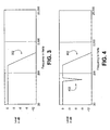
- FIG. 3 is a frequency response graph for an example vibration filter of an automotive audio controller including a bass-shelf filter.
- FIG. 4 is a frequency response graph for a second example vibration filter of an automotive audio controller including a notch filter with a bass-shelf filter.
- FIG. 5 is a block diagram for a second example automotive audio controller including a speed sensor and a speed estimator.
- FIG. 6 is an example flow chart for the second example automotive audio controller of FIG. 5.
- FIG. 7 is a block diagram for a third example automotive audio controller including volume control.
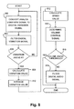
- FIG. 8 is an example flow chart for the third example automotive audio controller of FIG. 7.
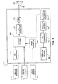
- FIG. 1 A first example automotive audio controller 102 for use in an automobile is shown in FIG. 1.
- the term "automotive audio controllers” as used herein refers to items known in the vernacular as “car stereos” or “car stereo components.” Automotive audio controllers are frequently installed in most types of motorized vehicles.
- the term “automobile” as used herein refers to motorized vehicles, such as motorcycles, boats, fixed or rotary wing aircraft, or any other vehicles that have an engine and transport passengers.
- the term “passenger compartment” is used herein to refer to a space in or on a vehicle that is occupied by passengers, such as the cabin of a car or an aircraft, or the space generally between the handlebars and the taillight of a motorcycle.
- the automotive audio controller 102 may be coupled to an analog audio source 104, a digital audio source 106, and at least one speaker 124.
- the automotive audio controller 102 may be configured to accept an analog audio signal from the analog audio source 104 and a digital audio signal from the digital audio source 106.
- the automotive audio controller 102 may generate a driving electrical signal to drive the speaker 124.
- the automotive audio controller 102 may include a vibration sensor 108 that generates a vibration level signal indicative of vibration.
- the driving electrical signal may be based on the analog and/or digital audio signals and the vibration level signal.
- the automotive audio controller 102 may "compensate" the driving electrical signal for ambient noise in the automobile passenger compartment by, for example, raising the level and/or changing the tone of the driving electrical signal in response to increases in the ambient noise level.
- the analog and/or digital audio signals may be multi-channel signals, such as stereo or surround sound signals.
- the automotive audio controller 102 may include an amplifier 122 that is coupled to the speaker 124.
- the amplifier 122 may comprise a stereo or multi-channel amplifier, such as a five or seven channel surround sound amplifier with or without a subwoofer amplifier.
- the speaker 124 may include a plurality of speakers coupled to the channels of the amplifier 122 to reproduce the stereo or multi-channel audio.
- the vibration sensor 108 may include any type of vibration sensor capable of sensing vibrations and generating an analog or digital signal indicating the frequency and amplitude of sensed vibrations.
- the vibration sensor 108 may include a mass loaded cantilever vibration sensor.
- One such vibration sensor is the Minisense 100-HT vibration sensor produced by Measurement Specialties, Inc. of Wayne, Pennsylvania.
- the vibration sensor 108 may be mounted to the automobile such that vibrations caused by interaction between the tires and the road or by wind moving across the automobile, as well as vibrations caused by the engine or other moving parts, excite (vibrate) the vibration sensor 108.
- the vibration sensor 108 may be mounted in the dash, under a seat, between the roof and the headliner, in one of the doors, in the trunk, to the frame, or the like.
- the analog audio source 104 may include a terrestrial or satellite radio receiver, a cassette tape player, a compact disc player ("CD player”), a minidisk player (“MD player”), an eight-track tape player, a digital audio tape player (“DAT player”), a digital versatile disc player (“DVD player”), an MPEG layer 3 audio player (“MP3 player”) or other devices that produce an analog audio signal.
- CD player compact disc player
- MD player minidisk player
- DAT player digital audio tape player
- DVD player digital versatile disc player
- MP3 player MPEG layer 3 audio player
- the digital audio source 106 may include a CD player, an MD player, DAT player, a DVD player, an MP3 player, a digital radio receiver, or a similar device that is capable of generating a digital audio output.
- the digital audio source 106 may provide, via an optical Toshiba® Link (“TOSLINK®”) and/or an electrical Sony® / Phillips® digital interface (“S/PDIF”), a pulse-code modulated (“PCM”), a digital theater systems (“DTS®”), or a Dolby® Digital signal.
- TOSLINK® optical Toshiba® Link
- S/PDIF electrical Sony® / Phillips® digital interface
- PCM pulse-code modulated
- DTS® digital theater systems
- Dolby® Digital signal a Dolby® Digital signal.
- the digital audio source 106 also may provide a digital audio signal through a wide area or local area network, such as such as a MOST® network, a COBRANet® network, an Ethernet® network, a universal serial bus (“USB®”) network, and/or other types of wired or wireless networks.
- a wide area or local area network such as such as a MOST® network, a COBRANet® network, an Ethernet® network, a universal serial bus (“USB®”) network, and/or other types of wired or wireless networks.
- the automotive audio controller 102 may include first and second analog-to-digital converters ("A/D converters”) 110 and 112, dynamic filters 118, vibration filters 114, a power estimator 116, a digital-to-analog converter ("D/A converter") 120, and an amplifier 122.
- the A/D converters 110 and 112 may each be a device that translates a continuously varying (analog) signal, such as a voltage or a current, to a succession of discrete digital values.
- Each A/D converter 110 and 112 may sample an analog signal periodically and produce a digital value representing the amplitude of the analog signal for each sample.
- the first A/D converter 110 may be coupled to the analog audio source 104 and may sample the analog audio signal at around 44.1 kHz or above and produce an 8-bit to 24-bit number representing the amplitude of the analog audio signal for each sample.
- the second A/D converter 112 may be coupled to the vibration sensor 108 and may sample the analog vibration signal at, for example, 1 kHz or above and produce a 4-bit to 24-bit number representing the amplitude of the vibration signal for each sample.
- the D/A converter 120 may be a device that translates digital data to an analog signal, such as a line-level signal.
- the D/A converter 120 may be coupled to and receive a succession of discrete digital values from the dynamic filters 118 as an input.
- the D/A converter 120 also may be coupled to the amplifier 122, and may create an analog signal as an output thereto, the amplitude of which corresponds to each digital value in time.
- the dynamic filters 118 may be a digital signal processor ("DSP") capable of receiving a plurality of digital audio signals and one or more control signals, and altering and/or switching between the digital audio signals either as a function of the control signals, or in a predetermined fashion.
- DSP digital signal processor
- the term "filters” is used here and elsewhere rather than terms such as “filter(s)” or “filtering means” to describe one or more filters, and should not be read to limit the claimed invention in any way.
- the dynamic filters 118 may be coupled to and receive digital audio signals from the first A/D converter 110 and the digital audio source 106.
- the dynamic filters 118 also may be coupled to and receive a control signal from the power estimator 116.
- the amplifier 122 may be an audio amplifier capable of receiving an analog audio signal, such as a line-level signal, and amplifying it to a level sufficient to a loudspeaker.
- the amplifier 122 may be an automotive stereo or surround sound amplifier.
- the amplifier 122 may be coupled to and receive an analog audio signal from the D/A converter 120.
- the amplifier 122 may be coupled to and provide a driving electrical signal to the speaker 124.
- the vibration filters 114 may be a DSP capable of receiving a digital vibration signals and altering the digital vibration signals in a predetermined fashion.
- the vibration filters 114 may be coupled to the second A/D converter 112.
- the power estimator 116 may be a DSP or a controller capable of generating a normalized power value indicative of the relative level of vibration sensed by the vibration sensor. For example, the power estimator may be tuned to a particular model of automobile, and may generate a normalized vibration power value between 0 and 100.
- the power estimator 116 may be coupled between the vibration filters 114 and the dynamic filters 118.
- the analog source 104 may transmit an analog audio signal to the first A/D converter 110.
- the first A/D converter 110 may convert the analog audio signal to a first digital audio signal, and transmit the first digital audio signal to the dynamic filters 118.
- the digital source 106 may transmit a second digital audio signal directly to the dynamic filters 118.
- the analog and digital audio signals may each be a monophonic, stereophonic, or multi-channel audio signal.
- the dynamic filters 118 may receive the digital audio signals from the digital source 106 and/or the first A/D converter 110. One of these digital audio signal may be selected, for example by a selection control signal (not shown), altered (filtered), and transmitted by the dynamic filters 118 to the D/A converter 120.
- the D/A converter 120 may convert the filtered digital audio signal to a filtered analog audio signal.
- the filtered analog audio signal may be sent by the D/A converter 120 to the amplifier 122.
- the amplifier 122 may amplify the filtered analog audio signal to drive the speaker 124.
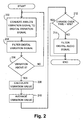
- FIG. 2 is an example flow chart for the first automotive audio controller 102.
- the second A/D converter 112 may convert an analog vibration signal from the vibration sensor 108 into a digital vibration signal.
- the vibration filters 114 may receive a digital vibration signal from the second A/D converter 112.
- the vibration filters 114 may implement a combination of bass-shelf (low pass), treble-shelf (high pass), Peak and/or Notch filters. Particular filters implemented in the vibration filters 114 may be customized for different automobile models.
- the vibration filters 114 may include a bass-shelf filter that has a cutoff frequency of 500 Hz.
- a frequency response plot for an example bass-shelf filter with a cutoff frequency 302 of 500 Hz is shown in FIG. 3.
- the vibration sensor 108 may be near a vibration source inside the automobile, such as an air conditioner fan vibrating at a frequency of 100 Hz.
- the vibration filters 114 may include a notch filter centered at 100 Hz, in addition to a bass-shelf filter that has a cutoff frequency of 500 Hz.
- a frequency response plot for an example notch filter with a center frequency 402 of 500 Hz combined with a bass-shelf filter that has a cutoff frequency 404 of 500 Hz is shown in FIG. 4.
- the vibration filters 114 also may include high-pass and low-pass filters of various orders.
- the vibration filters 114 may include a low-pass filter with a cutoff frequency of about 20 kHz to filter out vibrations above the audible range, and a high-pass filter with a cutoff frequency of about 2 Hz to filter out direct current (DC) signals.
- DC direct current
- the vibration filters 114 may transmit a filtered vibration signal to the power estimator 116.
- the power estimator 116 also may be customized for different automobile models.
- the power estimator 116 may generate a normalized vibration level value indicative of a relative level of vibration sensed by the vibration sensor, such that the normalized vibration level value is consistent from one automobile model to another.
- a first model of automobile may have a maximum filtered vibration signal level of 200
- a second model of automobile may have a maximum filtered vibration signal level of 50.
- the power estimator 116 may normalize the filtered vibration signal levels in the first automobile model by dividing by two, and normalize the filtered vibration signal levels in the second automobile model by multiplying by two. Such normalizing may allow the dynamic filters 118 to be designed for operation in a wider range of automobile models.
- the power estimator 116 may square and/or integrate and/or determine a root of the received filtered vibration signal to determine the normalized vibration level value. Where each of these three operations is carried out, the normalized vibration level value may be a function of the root-mean-square (RMS) power level of the filtered vibration signal.
- RMS root-mean-square
- the power estimator 116 may integrate (average) the received filtered vibration signal over time in order to smooth level transitions in the filtered signal.
- the filtered vibration signal may be averaged over a period of ten seconds. The averaging may lessen sudden, unnatural, adjustments to the filtered signal.
- the automobile hits a bump there may be an extreme, but short duration, increase in vibration level.
- a corresponding increase (without averaging) to the filtered signal could startle passengers, or have other negative consequences.
- the power estimator 116 may bound the normalized vibration level value over time. For example, the power estimator 116 may limit (bound) the normalized vibration level value to plus or minus around 15% of an averaged normalized vibration level value over a period of time, such as five seconds. Such bounding may help to reduce sudden, unnatural, adjustments to the filtered signal.
- the dynamic filters 118 may receive the normalized vibration level value from the power estimator 116 in addition to the audio signals.
- the dynamic filters 118 may include high-pass, band-pass, and/or low-pass filters of various orders to adjust the tone of the filtered digital audio signal, and also may be capable of adjusting the overall level of the filtered digital audio signal.
- the dynamic filters 118 may increase the level of the filtered digital audio signal as a function of the normalized vibration level value. For example, the level of the filtered digital audio signal may be increased proportionally to the normalized vibration level value.
- the dynamic filters 118 may increase the level of certain frequency ranges of the filtered digital audio signal as a function of the normalized vibration level value. For example, the "bass" (low frequency range) level of the filtered digital audio signal may be increased more than other frequency ranges.
- the automotive audio controller 102 may be configured differently for different models. For example, ambient noise and vibration characteristics may be measured for an automobile model on test tracks to determine ambient noise characteristics as a function of vibration. These measured characteristics may be used to configure the vibration filters 114, the power estimator 116, and the dynamic filters 118 for the automobile model.
- a second example automotive audio controller 502 is shown in FIG. 5 including a speed sensor 504 and a speed estimator 506.
- the automotive audio controller 502 may be configured to accept analog and/or digital audio signals and include the vibration sensor 108 to generate a vibration level signal, in the same manner as the first automotive audio controller 102 described above.
- the second automotive audio controller 502 also may be coupled to and receive a speed signal from a speed sensor 504.
- the speed sensor 504 may be, for example, a speedometer having a digital output.
- the speed sensor may transmit the speed signal directly to the automotive audio controller 502, or may transmit the speed signal through an automotive interface bus.
- the automotive audio controller 502 may generate a driving electrical signal to drive the speaker 124 in the same manner as the automotive audio controller 102.
- the automotive audio controller 502 may include the A/D converters 110 and 112, the vibration filters 114, the power estimator 116, the D/A converter 120, the amplifier 122, a speed estimator 506, and dynamic filters 508. Except for the speed sensor 506, the components of the second example automotive audio controller 502 may be configured in the same manner as the components in the first example automotive controller 102.
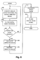
- FIG. 6 is an example flow chart for the second automotive audio controller 502. At 602-610, the second automotive audio controller 502 may operate in the same fashion as the first automotive audio controller 102.
- the speed estimator 506 may be coupled between the speed sensor 504 and the dynamic filters 508. At 612, the speed estimator 506 may receive the speed signal from the speed sensor 504 and convert the speed signal into a speed value, such as a numerical indicator of speed in kilometers per hour or miles per hour. The speed estimator 506 may transmit the speed value to the dynamic filters 508.
- a speed value such as a numerical indicator of speed in kilometers per hour or miles per hour.
- the speed estimator 506 may transmit the speed value to the dynamic filters 508.
- the dynamic filters 508 may be a DSP capable of receiving a plurality of digital audio signals and one or more control signals, and altering and/or switching between the digital audio signals either as a function of the control signals, or in a predetermined fashion.
- the dynamic filters 508 may receive the normalized vibration level value from the power estimator 116 and the speed value from the speed estimator 506 in addition to the audio signals.
- the dynamic filters 508 may include high-pass, band-pass, and/or low-pass filters of various orders to adjust the tone and/or the level of the filtered digital audio signal.
- the dynamic filters 508 may increase the level of the filtered digital audio signal as a function of the normalized vibration level value, as a function of the speed value, or as a function of both.
- the level of the filtered digital audio signal may be increased proportionally to the normalized vibration level value, proportionally to the speed value, or proportionally to both the normalized vibration level value and the speed value.
- the dynamic filters 508 may increase the level of certain frequency ranges of the filtered digital audio signal as a function of the normalized vibration level value, as a function of the speed value, or as a function of both.
- the "bass" (low frequency range) level of the filtered digital audio signal may be increased more than other frequency ranges when the normalized vibration level value increases
- the "treble" (high frequency range) level of the filtered digital audio signal may be increased more than other frequency ranges when the speed value increases.
- Such a configuration may be desirable where a high speed value indicates an increase in wind noise, which may be concentrated in higher frequencies for a certain automobile model.
- a third example automotive audio controller 702 is shown in FIG. 7.
- the automotive audio controller 702 may be configured to accept analog and/or digital audio signals and a speed signal, and include the vibration sensor 108 to generate a vibration level signal, in the same manner as the first and second automotive audio controllers 102 and 502.
- the third automotive audio controller 702 may include the A/D converters 110 and 112, the vibration filters 114, the power estimator 116, the D/A converter 120, the amplifier 122, the speed estimator 506, and dynamic filters 706.
- the dynamic filters 706 may be a DSP capable of receiving a plurality of digital audio signals and one or more control signals, and altering and/or switching between the digital audio signals either as a function of the control signals, or in a predetermined fashion.
- the components of the third example automotive audio controller 702 may be configured in the same manner as the components in the second example automotive controller 502.
- the third automotive audio controller 702 may, however, also be coupled to a volume control 704.
- the third automotive audio controller 702 may receive a volume control signal from the volume control 704.
- the volume control 704 may be, for example, a manually actuated potentiometer with an A/D converter to generate a volume control signal, a jog/shuttle control generating pulses, or the like.
- FIG. 8 is an example flow chart for the second automotive audio controller 702.
- the third automotive audio controller 702 may operate in the same fashion as the second automotive audio controller 502.
- the volume control 704 may transmit the volume control signal directly to the third automotive audio controller 702, or may transmit the volume control signal through an automotive interface bus.
- the third automotive audio controller 702 may generate a driving electrical signal to drive the speaker 124 in the same manner as the automotive audio controller 502.
- the dynamic filters 706 may receive the normalized vibration level value from the power estimator 116, the speed signal from the speed estimator 506, and the volume control signal from the volume control 704 in addition to the audio signals.
- the dynamic filters 706 may include high-pass, band-pass, and/or low-pass filters of various orders to adjust the tone of the filtered digital audio signal, and also may adjust the level of the filtered digital audio signal.
- the dynamic filters 706 may increase the level of the filtered digital audio signal as a function of the volume control signal, and also as a function of the normalized vibration level value and/or the speed value.
- the level of the filtered digital audio signal may be increased proportionally to a level of the volume control signal.
- the level of the volume control signal when the level of the volume control signal is low (i.e., below a first threshold), at 818 the level of the filtered digital audio signal may be increased at a first rate based on the normalized vibration level value, at a first rate based on the speed value, or at a first rate based on both the normalized vibration level value and the speed value.
- the level of the filtered digital audio signal may be increased at a second rate based on the normalized vibration level value and/or the speed value, because the "apparent volume” level may not decrease by the same amount when the level of the filtered digital audio signal is already raised.
- the volume control signal is "high” (i.e., above the second threshold)
- the level of the filtered digital audio signal may stay constant irrespective of the normalized vibration level value and/or the speed value, because there may be no significant change in the "apparent volume” level due to ambient noise.
- the dynamic filters 706 may increase the level of certain frequency ranges of the filtered digital audio signal to a greater or lesser degree depending on the volume control signal. For example, at 816 when the volume control signal is high, at 818 the dynamic filters 706 may increase the treble less than the bass in response to increased normalized vibration level and/or speed values.
- the first, second, and third automotive audio controllers 102, 502, and 702 may be constructed so that the vibration sensor 108 is in a housing with the amplifier 122. In this configuration, heat generated by the amplifier 122 may distort the vibration signal. Therefore, the audio controllers 102, 502, and 702 may each include a temperature sensor (not shown) near the vibration sensor 108. The temperature sensor may produce a temperature value that can be used by the vibration filters 114 and/or the power estimator 116 to compensate for heat-induced variations in the normalized vibration level value.
- the vibration sensor 108 may be located in an automobiles trunk, or in another area "isolated" from the passenger compartment. Furthermore, because the automotive audio controllers 102, 502, and 702 do not directly measure ambient noise, there is a reduced possibility of "feedback" from audio reproduced by the speaker 124, or of passenger conversations being detected as noise.
Abstract
Description
- This invention relates to a sound system for an automobile, and more particularly, to a sound system capable of dynamically adjusting gain and tone characteristics for a reproduced audio signal in accordance with a vibration level in the automobile.
- Human perception of acoustic signals, such as an audio signal (music, speech, etc.) generated by an audio reproduction system, is affected by the presence of ambient noise. Therefore, audio reproduction systems designed to operate in noisy environments, such as inside an automobile, often contain components that attempt to compensate for perceived degradation of the audio signal caused by noise.
- Ambient noise in automobiles, caused by, for example, the engine or the interaction of the tires and the road surface, may not be band-limited but usually has strong components below approximately 200 Hz. This low frequency ambient noise causes problems for automotive audio reproduction systems. First, the volume of the signal as perceived by a listener, commonly referred to as the "apparent volume," is a function of the noise, and hence, the apparent volume decreases as the noise increases. Listeners may wish to maintain the apparent volume at a constant level, but this is difficult as the ambient noise changes dynamically in an automobile, for example, because of changing road conditions and/or changing automobile speeds. This problem often is referred to as the "apparent volume problem."
- One method of compensating for the apparent volume problem, referred to as the "noise-only-method," involves increasing the gain of the signal as a function of the ambient noise. This method prevents soft passages from being overwhelmed by the noise. However, the method may be disadvantageous because it varies the gain irrespective of the volume level set by the user, so the method increases the gain in response to increasing noise even for very high volume levels. These increases may result in producing signals that are painfully loud for a listener, harmful to the audio reproduction equipment, or both.
- In an automobile, the ambient noise is concentrated in the low frequency range, so signals are masked more in lower frequency ranges than in higher frequency ranges. This causes the signals to lose their desired tone. This problem often is referred to as the "uneven masking problem."
- In general, systems designed to compensate for either the apparent volume problem or the uneven masking problem include some way of estimating the level of the ambient noise. Some automotive audio reproduction systems use a microphone located inside the passenger compartment of the automobile to measure ambient noise. The use of a microphone in the passenger compartment, however, may have several disadvantages. Since the microphone is generally sensitive to all sounds in the automobile, including the signals generated by the audio reproduction system, it may be necessary to filter the signal generated by the microphone to yield a signal representative of the noise.
- One method for filtering the microphone output signal involves use a low pass filter to remove higher frequencies where the reproduced audio signal may be concentrated. This method, however, may generate a signal that represents only the sub-audio low-frequency noise, rather than the actual masking noise that may contain higher frequencies. Another method of filtering the microphone signal is to subtract the reproduced audio signal from the microphone signal to obtain a signal representative of the noise. This method may be disadvantageous because it involves the transfer function from the speakers of the audio reproduction system to the microphone. The transfer function may be difficult to determine, and, moreover, may vary dynamically, for example, with changes in the number of passengers in the automobile. Furthermore, using a microphone in the passenger compartment of the automobile may cause increases in the signal in response to speech of passengers, so that the audio reproduction system may attempt to "drown out" conversations.
- Other methods implementing complex systems of sensors and digital signal processors also have been used to compensate for ambient noise in an automobile. Many of these complex systems are not economically feasible for use in mass produced automobiles. None of these prior systems provides both an economically viable and satisfactory sounding solution. Hence, it would be desirable to provide a satisfactory sounding and economical automobile sound system that compensates for ambient noise in the automobile.
- An automotive audio controller is provided for receiving an audio signal from an audio source and providing a filtered audio signal that compensates for ambient noise in the automobile. The audio controller may have a vibration sensor that generates a vibration signal indicative of vibrations in the automobile. A dynamic filter of the audio controller may receive the vibration signal and the audio signal, and change the gain level and/or tone of the audio signal based on the vibration signal to generate the filtered audio signal. For example, the dynamic filter may increase the gain level of the audio signal as the vibration signal increases to generate the filtered audio signal.
- The audio controller also may receive a speed signal and change the gain level and/or tone of the audio signal based on the speed signal to generate the filtered audio signal. For example, the dynamic filter may increase the gain level of the audio signal as the speed signal increases to generate the filtered audio signal. The audio controller also may receive a volume control signal. The volume control signal may affect how the dynamic filter changes the audio signal as a function of the vibration and/or speed signals. For example, when the volume control signal is low, the dynamic filter may increase the gain level of the audio signal by a first factor as the speed signal and/or the vibration signal increases in order to generate the filtered audio signal. When the volume control signal is high, however, the dynamic filter may increase the gain level of the audio signal by a second factor, or not at all, as the speed signal and/or the vibration signal increases in order to generate the filtered audio signal.
- Other systems, methods, features and advantages of the invention will be, or will become, apparent to one with skill in the art upon examination of the following figures and detailed description. It is intended that all such additional systems, methods, features and advantages be included within this description, be within the scope of the invention, and be protected by the following claims.
- The invention can be better understood with reference to the following figures. The components in the figures are not necessarily to scale; emphasis is instead being placed upon illustrating the principles of the invention. Moreover, in the figures, like reference numerals designate corresponding parts throughout the different views.
- FIG. 1 is a block diagram for an example automotive audio controller.
- FIG. 2 is an example flow chart for the example automotive audio controller of FIG. 1.
- FIG. 3 is a frequency response graph for an example vibration filter of an automotive audio controller including a bass-shelf filter.
- FIG. 4 is a frequency response graph for a second example vibration filter of an automotive audio controller including a notch filter with a bass-shelf filter.
- FIG. 5 is a block diagram for a second example automotive audio controller including a speed sensor and a speed estimator.
- FIG. 6 is an example flow chart for the second example automotive audio controller of FIG. 5.
- FIG. 7 is a block diagram for a third example automotive audio controller including volume control.
- FIG. 8 is an example flow chart for the third example automotive audio controller of FIG. 7.
- A first example
automotive audio controller 102 for use in an automobile is shown in FIG. 1. The term "automotive audio controllers" as used herein refers to items known in the vernacular as "car stereos" or "car stereo components." Automotive audio controllers are frequently installed in most types of motorized vehicles. The term "automobile" as used herein refers to motorized vehicles, such as motorcycles, boats, fixed or rotary wing aircraft, or any other vehicles that have an engine and transport passengers. The term "passenger compartment" is used herein to refer to a space in or on a vehicle that is occupied by passengers, such as the cabin of a car or an aircraft, or the space generally between the handlebars and the taillight of a motorcycle. - The
automotive audio controller 102 may be coupled to ananalog audio source 104, adigital audio source 106, and at least onespeaker 124. Theautomotive audio controller 102 may be configured to accept an analog audio signal from theanalog audio source 104 and a digital audio signal from the digitalaudio source 106. Theautomotive audio controller 102 may generate a driving electrical signal to drive thespeaker 124. Theautomotive audio controller 102 may include avibration sensor 108 that generates a vibration level signal indicative of vibration. The driving electrical signal may be based on the analog and/or digital audio signals and the vibration level signal. Theautomotive audio controller 102 may "compensate" the driving electrical signal for ambient noise in the automobile passenger compartment by, for example, raising the level and/or changing the tone of the driving electrical signal in response to increases in the ambient noise level. - The analog and/or digital audio signals may be multi-channel signals, such as stereo or surround sound signals. The
automotive audio controller 102 may include anamplifier 122 that is coupled to thespeaker 124. Theamplifier 122 may comprise a stereo or multi-channel amplifier, such as a five or seven channel surround sound amplifier with or without a subwoofer amplifier. Likewise, thespeaker 124 may include a plurality of speakers coupled to the channels of theamplifier 122 to reproduce the stereo or multi-channel audio. - The
vibration sensor 108 may include any type of vibration sensor capable of sensing vibrations and generating an analog or digital signal indicating the frequency and amplitude of sensed vibrations. For example, thevibration sensor 108 may include a mass loaded cantilever vibration sensor. One such vibration sensor is the Minisense 100-HT vibration sensor produced by Measurement Specialties, Inc. of Wayne, Pennsylvania. Thevibration sensor 108 may be mounted to the automobile such that vibrations caused by interaction between the tires and the road or by wind moving across the automobile, as well as vibrations caused by the engine or other moving parts, excite (vibrate) thevibration sensor 108. For example, thevibration sensor 108 may be mounted in the dash, under a seat, between the roof and the headliner, in one of the doors, in the trunk, to the frame, or the like. - The
analog audio source 104 may include a terrestrial or satellite radio receiver, a cassette tape player, a compact disc player ("CD player"), a minidisk player ("MD player"), an eight-track tape player, a digital audio tape player ("DAT player"), a digital versatile disc player ("DVD player"), anMPEG layer 3 audio player ("MP3 player") or other devices that produce an analog audio signal. - The digital
audio source 106 may include a CD player, an MD player, DAT player, a DVD player, an MP3 player, a digital radio receiver, or a similar device that is capable of generating a digital audio output. For example, the digitalaudio source 106 may provide, via an optical Toshiba® Link ("TOSLINK®") and/or an electrical Sony® / Phillips® digital interface ("S/PDIF"), a pulse-code modulated ("PCM"), a digital theater systems ("DTS®"), or a Dolby® Digital signal. The digitalaudio source 106 also may provide a digital audio signal through a wide area or local area network, such as such as a MOST® network, a COBRANet® network, an Ethernet® network, a universal serial bus ("USB®") network, and/or other types of wired or wireless networks. - The
automotive audio controller 102 may include first and second analog-to-digital converters ("A/D converters") 110 and 112,dynamic filters 118, vibration filters 114, apower estimator 116, a digital-to-analog converter ("D/A converter") 120, and anamplifier 122. The A/D converters D converter - For example, the first A/
D converter 110 may be coupled to theanalog audio source 104 and may sample the analog audio signal at around 44.1 kHz or above and produce an 8-bit to 24-bit number representing the amplitude of the analog audio signal for each sample. The second A/D converter 112 may be coupled to thevibration sensor 108 and may sample the analog vibration signal at, for example, 1 kHz or above and produce a 4-bit to 24-bit number representing the amplitude of the vibration signal for each sample. The D/A converter 120 may be a device that translates digital data to an analog signal, such as a line-level signal. The D/A converter 120 may be coupled to and receive a succession of discrete digital values from thedynamic filters 118 as an input. The D/A converter 120 also may be coupled to theamplifier 122, and may create an analog signal as an output thereto, the amplitude of which corresponds to each digital value in time. - The
dynamic filters 118 may be a digital signal processor ("DSP") capable of receiving a plurality of digital audio signals and one or more control signals, and altering and/or switching between the digital audio signals either as a function of the control signals, or in a predetermined fashion. The term "filters" is used here and elsewhere rather than terms such as "filter(s)" or "filtering means" to describe one or more filters, and should not be read to limit the claimed invention in any way. Thedynamic filters 118 may be coupled to and receive digital audio signals from the first A/D converter 110 and the digitalaudio source 106. Thedynamic filters 118 also may be coupled to and receive a control signal from thepower estimator 116. - The
amplifier 122 may be an audio amplifier capable of receiving an analog audio signal, such as a line-level signal, and amplifying it to a level sufficient to a loudspeaker. For example, theamplifier 122 may be an automotive stereo or surround sound amplifier. Theamplifier 122 may be coupled to and receive an analog audio signal from the D/A converter 120. Theamplifier 122 may be coupled to and provide a driving electrical signal to thespeaker 124. - The vibration filters 114 may be a DSP capable of receiving a digital vibration signals and altering the digital vibration signals in a predetermined fashion. The vibration filters 114 may be coupled to the second A/
D converter 112. Thepower estimator 116 may be a DSP or a controller capable of generating a normalized power value indicative of the relative level of vibration sensed by the vibration sensor. For example, the power estimator may be tuned to a particular model of automobile, and may generate a normalized vibration power value between 0 and 100. Thepower estimator 116 may be coupled between the vibration filters 114 and the dynamic filters 118. - In FIG. 1, the
analog source 104 may transmit an analog audio signal to the first A/D converter 110. The first A/D converter 110 may convert the analog audio signal to a first digital audio signal, and transmit the first digital audio signal to the dynamic filters 118. Thedigital source 106 may transmit a second digital audio signal directly to the dynamic filters 118. The analog and digital audio signals may each be a monophonic, stereophonic, or multi-channel audio signal. - The
dynamic filters 118 may receive the digital audio signals from thedigital source 106 and/or the first A/D converter 110. One of these digital audio signal may be selected, for example by a selection control signal (not shown), altered (filtered), and transmitted by thedynamic filters 118 to the D/A converter 120. The D/A converter 120 may convert the filtered digital audio signal to a filtered analog audio signal. The filtered analog audio signal may be sent by the D/A converter 120 to theamplifier 122. Theamplifier 122 may amplify the filtered analog audio signal to drive thespeaker 124. - FIG. 2 is an example flow chart for the first
automotive audio controller 102. At 202, the second A/D converter 112 may convert an analog vibration signal from thevibration sensor 108 into a digital vibration signal. At 204, the vibration filters 114 may receive a digital vibration signal from the second A/D converter 112. The vibration filters 114 may implement a combination of bass-shelf (low pass), treble-shelf (high pass), Peak and/or Notch filters. Particular filters implemented in the vibration filters 114 may be customized for different automobile models. - For example, in a certain automobile model ambient noise in the passenger compartment may be caused primarily by vibrations in the frequency range of 20 Hz to 500 Hz. Therefore, the vibration filters 114 may include a bass-shelf filter that has a cutoff frequency of 500 Hz. A frequency response plot for an example bass-shelf filter with a
cutoff frequency 302 of 500 Hz is shown in FIG. 3. - For further example, the
vibration sensor 108 may be near a vibration source inside the automobile, such as an air conditioner fan vibrating at a frequency of 100 Hz. To prevent such a vibration source from distorting the vibration signal, the vibration filters 114 may include a notch filter centered at 100 Hz, in addition to a bass-shelf filter that has a cutoff frequency of 500 Hz. A frequency response plot for an example notch filter with acenter frequency 402 of 500 Hz combined with a bass-shelf filter that has a cutoff frequency 404 of 500 Hz is shown in FIG. 4. - The vibration filters 114 also may include high-pass and low-pass filters of various orders. For example, the vibration filters 114 may include a low-pass filter with a cutoff frequency of about 20 kHz to filter out vibrations above the audible range, and a high-pass filter with a cutoff frequency of about 2 Hz to filter out direct current (DC) signals.
- The vibration filters 114 may transmit a filtered vibration signal to the
power estimator 116. Thepower estimator 116 also may be customized for different automobile models. For example, thepower estimator 116 may generate a normalized vibration level value indicative of a relative level of vibration sensed by the vibration sensor, such that the normalized vibration level value is consistent from one automobile model to another. A first model of automobile may have a maximum filtered vibration signal level of 200, and a second model of automobile may have a maximum filtered vibration signal level of 50. Thepower estimator 116 may normalize the filtered vibration signal levels in the first automobile model by dividing by two, and normalize the filtered vibration signal levels in the second automobile model by multiplying by two. Such normalizing may allow thedynamic filters 118 to be designed for operation in a wider range of automobile models. - At 208, the
power estimator 116 may square and/or integrate and/or determine a root of the received filtered vibration signal to determine the normalized vibration level value. Where each of these three operations is carried out, the normalized vibration level value may be a function of the root-mean-square (RMS) power level of the filtered vibration signal. - At 210, the
power estimator 116 may integrate (average) the received filtered vibration signal over time in order to smooth level transitions in the filtered signal. For example, the filtered vibration signal may be averaged over a period of ten seconds. The averaging may lessen sudden, unnatural, adjustments to the filtered signal. When the automobile hits a bump, there may be an extreme, but short duration, increase in vibration level. For a large bump, a corresponding increase (without averaging) to the filtered signal could startle passengers, or have other negative consequences. - In addition to averaging the filtered vibration signal over time, at 212 the
power estimator 116 also may bound the normalized vibration level value over time. For example, thepower estimator 116 may limit (bound) the normalized vibration level value to plus or minus around 15% of an averaged normalized vibration level value over a period of time, such as five seconds. Such bounding may help to reduce sudden, unnatural, adjustments to the filtered signal. - At 214, the
dynamic filters 118 may receive the normalized vibration level value from thepower estimator 116 in addition to the audio signals. Thedynamic filters 118 may include high-pass, band-pass, and/or low-pass filters of various orders to adjust the tone of the filtered digital audio signal, and also may be capable of adjusting the overall level of the filtered digital audio signal. To compensate for changes to the "apparent volume" level of the filtered digital audio signal, thedynamic filters 118 may increase the level of the filtered digital audio signal as a function of the normalized vibration level value. For example, the level of the filtered digital audio signal may be increased proportionally to the normalized vibration level value. - To compensate for "uneven masking" of the filtered digital audio signal by ambient noise, the
dynamic filters 118 may increase the level of certain frequency ranges of the filtered digital audio signal as a function of the normalized vibration level value. For example, the "bass" (low frequency range) level of the filtered digital audio signal may be increased more than other frequency ranges. - Different automobile models may produce different ambient noise for the same vibration level. To compensate for these differences, the
automotive audio controller 102 may be configured differently for different models. For example, ambient noise and vibration characteristics may be measured for an automobile model on test tracks to determine ambient noise characteristics as a function of vibration. These measured characteristics may be used to configure the vibration filters 114, thepower estimator 116, and thedynamic filters 118 for the automobile model. - A second example
automotive audio controller 502 is shown in FIG. 5 including aspeed sensor 504 and aspeed estimator 506. Theautomotive audio controller 502 may be configured to accept analog and/or digital audio signals and include thevibration sensor 108 to generate a vibration level signal, in the same manner as the firstautomotive audio controller 102 described above. The secondautomotive audio controller 502 also may be coupled to and receive a speed signal from aspeed sensor 504. Thespeed sensor 504 may be, for example, a speedometer having a digital output. The speed sensor may transmit the speed signal directly to theautomotive audio controller 502, or may transmit the speed signal through an automotive interface bus. Theautomotive audio controller 502 may generate a driving electrical signal to drive thespeaker 124 in the same manner as theautomotive audio controller 102. - The
automotive audio controller 502 may include the A/D converters power estimator 116, the D/A converter 120, theamplifier 122, aspeed estimator 506, anddynamic filters 508. Except for thespeed sensor 506, the components of the second exampleautomotive audio controller 502 may be configured in the same manner as the components in the first exampleautomotive controller 102. FIG. 6 is an example flow chart for the secondautomotive audio controller 502. At 602-610, the secondautomotive audio controller 502 may operate in the same fashion as the firstautomotive audio controller 102. - The
speed estimator 506 may be coupled between thespeed sensor 504 and the dynamic filters 508. At 612, thespeed estimator 506 may receive the speed signal from thespeed sensor 504 and convert the speed signal into a speed value, such as a numerical indicator of speed in kilometers per hour or miles per hour. Thespeed estimator 506 may transmit the speed value to the dynamic filters 508. - The
dynamic filters 508 may be a DSP capable of receiving a plurality of digital audio signals and one or more control signals, and altering and/or switching between the digital audio signals either as a function of the control signals, or in a predetermined fashion. Thedynamic filters 508 may receive the normalized vibration level value from thepower estimator 116 and the speed value from thespeed estimator 506 in addition to the audio signals. Thedynamic filters 508 may include high-pass, band-pass, and/or low-pass filters of various orders to adjust the tone and/or the level of the filtered digital audio signal. - At 614, to compensate for changes to the "apparent volume" level of the filtered digital audio signal, the
dynamic filters 508 may increase the level of the filtered digital audio signal as a function of the normalized vibration level value, as a function of the speed value, or as a function of both. For example, the level of the filtered digital audio signal may be increased proportionally to the normalized vibration level value, proportionally to the speed value, or proportionally to both the normalized vibration level value and the speed value. - Also at 614, to compensate for "uneven masking" of the filtered digital audio signal by ambient noise, the
dynamic filters 508 may increase the level of certain frequency ranges of the filtered digital audio signal as a function of the normalized vibration level value, as a function of the speed value, or as a function of both. For example, the "bass" (low frequency range) level of the filtered digital audio signal may be increased more than other frequency ranges when the normalized vibration level value increases, and the "treble" (high frequency range) level of the filtered digital audio signal may be increased more than other frequency ranges when the speed value increases. Such a configuration may be desirable where a high speed value indicates an increase in wind noise, which may be concentrated in higher frequencies for a certain automobile model. - A third example automotive audio controller 702 is shown in FIG. 7. The automotive audio controller 702 may be configured to accept analog and/or digital audio signals and a speed signal, and include the
vibration sensor 108 to generate a vibration level signal, in the same manner as the first and secondautomotive audio controllers - The third automotive audio controller 702 may include the A/
D converters power estimator 116, the D/A converter 120, theamplifier 122, thespeed estimator 506, anddynamic filters 706. Thedynamic filters 706 may be a DSP capable of receiving a plurality of digital audio signals and one or more control signals, and altering and/or switching between the digital audio signals either as a function of the control signals, or in a predetermined fashion. The components of the third example automotive audio controller 702 may be configured in the same manner as the components in the second exampleautomotive controller 502. - The third automotive audio controller 702 may, however, also be coupled to a
volume control 704. The third automotive audio controller 702 may receive a volume control signal from thevolume control 704. Thevolume control 704 may be, for example, a manually actuated potentiometer with an A/D converter to generate a volume control signal, a jog/shuttle control generating pulses, or the like. - FIG. 8 is an example flow chart for the second automotive audio controller 702. At 802-812, the third automotive audio controller 702 may operate in the same fashion as the second
automotive audio controller 502. At 814, thevolume control 704 may transmit the volume control signal directly to the third automotive audio controller 702, or may transmit the volume control signal through an automotive interface bus. The third automotive audio controller 702 may generate a driving electrical signal to drive thespeaker 124 in the same manner as theautomotive audio controller 502. - The
dynamic filters 706 may receive the normalized vibration level value from thepower estimator 116, the speed signal from thespeed estimator 506, and the volume control signal from thevolume control 704 in addition to the audio signals. Thedynamic filters 706 may include high-pass, band-pass, and/or low-pass filters of various orders to adjust the tone of the filtered digital audio signal, and also may adjust the level of the filtered digital audio signal. To compensate for changes to the "apparent volume" level of the filtered digital audio signal, thedynamic filters 706 may increase the level of the filtered digital audio signal as a function of the volume control signal, and also as a function of the normalized vibration level value and/or the speed value. - For example, the level of the filtered digital audio signal may be increased proportionally to a level of the volume control signal. At 816, when the level of the volume control signal is low (i.e., below a first threshold), at 818 the level of the filtered digital audio signal may be increased at a first rate based on the normalized vibration level value, at a first rate based on the speed value, or at a first rate based on both the normalized vibration level value and the speed value. At 816, when the level of the volume control signal is "medium" (i.e., above the first threshold but below a second threshold), at 818 the level of the filtered digital audio signal may be increased at a second rate based on the normalized vibration level value and/or the speed value, because the "apparent volume" level may not decrease by the same amount when the level of the filtered digital audio signal is already raised. At 818, when the volume control signal is "high" (i.e., above the second threshold), the level of the filtered digital audio signal may stay constant irrespective of the normalized vibration level value and/or the speed value, because there may be no significant change in the "apparent volume" level due to ambient noise.
- Similarly, to compensate for "uneven masking" of the filtered digital audio signal by ambient noise, at 818 the
dynamic filters 706 may increase the level of certain frequency ranges of the filtered digital audio signal to a greater or lesser degree depending on the volume control signal. For example, at 816 when the volume control signal is high, at 818 thedynamic filters 706 may increase the treble less than the bass in response to increased normalized vibration level and/or speed values. - The first, second, and third
automotive audio controllers vibration sensor 108 is in a housing with theamplifier 122. In this configuration, heat generated by theamplifier 122 may distort the vibration signal. Therefore, theaudio controllers vibration sensor 108. The temperature sensor may produce a temperature value that can be used by the vibration filters 114 and/or thepower estimator 116 to compensate for heat-induced variations in the normalized vibration level value. - Because the
automotive audio controllers vibration sensor 108 as well as theautomotive audio controllers automotive audio controllers speaker 124, or of passenger conversations being detected as noise. - While various embodiments of the invention have been described, it will be apparent to those of ordinary skill in the art that many more embodiments and implementations are possible that are within the scope of the invention. Accordingly, the invention is not to be restricted except in light of the attached claims and their equivalents.
Claims (45)
- An automotive audio controller for receiving an audio signal from an audio source and providing a filtered audio signal, the audio controller comprising:where the dynamic filter is configured to generate a filtered audio signal as a function of the audio signal and the vibration signal.a vibration sensor coupled to an automobile and configured to generate a vibration signal indicative of a vibration level associated with the automobile;a dynamic filter coupled to the vibration sensor to receive the vibration signal and coupled to an audio source to receive an audio signal; and
- The automotive audio controller of claim 1, further comprising an amplifier coupled to the dynamic filter and configured to receive the filtered audio signal and generate a driving electrical signal for a speaker.
- The automotive audio controller of claim 1, further comprising an A/D converter coupled between the vibration sensor and the dynamic filter for converting the vibration signal to a digital vibration signal.
- The automotive audio controller of claim 1, further comprising a vibration filter coupled between the vibration sensor and the dynamic filter, where the vibration filter alters the vibration signal.
- The automotive audio controller of claim 4, where the vibration filter comprises a low-pass filter having a cutoff frequency of between about 100 Hz and about 1 kHz, and the low-pass filter that attenuates frequencies of the vibration signal below the cutoff frequency.
- The automotive audio controller of claim 4, where the vibration filter comprises a low-pass filter having a cutoff frequency of between about 2 kHz and about 20 kHz, and the low-pass filter attenuates frequencies of the vibration signal below the cutoff frequency.
- The automotive audio controller of claim 4, where the vibration filter comprises a high-pass filter having a cutoff frequency of between about 2 Hz and about 20 Hz, and the high-pass filter attenuates frequencies of the vibration signal below the cutoff frequency.
- The automotive audio controller of claim 4, where the vibration filter comprises a notch filter.
- The automotive audio controller of claim 1, further comprising a power estimator coupled between the vibration sensor and the dynamic filter, where the power estimator receives the vibration signal and converts the vibration signal into a power value that is indicative of the vibration level sensed by the vibration sensor.
- The automotive audio controller of claim 9, where the power value is normalized.
- The automotive audio controller of claim 9, where the power estimator converts the vibration signal into a power value by integrating the vibration signal over time.
- The automotive audio controller of claim 9, where the power estimator converts the vibration signal into a power value by integrating a square of the vibration signal over time.
- The automotive audio controller of claim 9, where the power estimator converts the vibration signal into a power value limiting changes to the power value over time.
- The automotive audio controller of claim 1, where the dynamic filter is configured to generate the filtered audio signal by increasing a gain value of the audio signal based on the vibration level of the vibration signal.
- The automotive audio controller of claim 1, where the dynamic filter is configured to generate the filtered audio signal by increasing a gain value of the audio signal as the vibration level of the vibration signal increases.
- An automotive audio controller for receiving an audio signal from an audio source and providing a filtered audio signal, the audio controller comprising:where the dynamic filter is configured to generate a filtered audio signal as a function of the audio signal, the vibration signal, and the speed signal.a vibration sensor coupled to an automobile and configured to generate a vibration signal indicative of a vibration level of the automobile;a dynamic filter coupled to the vibration sensor to receive the vibration signal, coupled to an audio source to receive an audio signal, and coupled to a speed sensor to receive a speed signal; and
- The loudspeaker system of claim 16, further comprising an A/D converter coupled between the speed sensor and the dynamic filter.
- The automotive audio controller of claim 16, where the dynamic filter is configured to generate the filtered audio signal by increasing a gain value of the audio signal based on the vibration level of the vibration signal.
- The automotive audio controller of claim 18, where the dynamic filter is configured to generate the filtered audio signal by increasing a gain value of the audio signal as a function of the speed signal.
- The automotive audio controller of claim 16, where the dynamic filter is configured to generate the filtered audio signal by increasing a gain value of the audio signal as the vibration level of the vibration signal increases.
- The automotive audio controller of claim 20, where the dynamic filter is configured to generate the filtered audio signal by increasing the gain of the audio signal as a level of the speed signal increases.
- The automotive audio controller of claim 16, further comprising a vibration filter coupled between the vibration sensor and the dynamic filter, where the vibration filter alters the vibration signal.
- The automotive audio controller of claim 22, where the vibration filter comprises a low-pass filter having a cutoff frequency of between about 100 Hz and about 1 kHz, and the low-pass filter that attenuates frequencies of the vibration signal below the cutoff frequency.
- The automotive audio controller of claim 16, further comprising an amplifier coupled to the dynamic filter and configured to receive the filtered audio signal and generate a driving electrical signal for a speaker.
- An automotive audio controller for receiving an audio signal from an audio source and providing a filtered audio signal, the audio controller comprising:where the dynamic filter is configured to generate a filtered audio signal as a function of the audio signal, the vibration signal, the speed signal, and the volume control signal.a vibration sensor coupled to an automobile and configured to generate a vibration signal indicative of a vibration level of the automobile;a dynamic filter coupled to the vibration sensor to receive the vibration signal, coupled to an audio source to receive an audio signal, coupled to a speed sensor to receive a speed signal, and coupled to a volume control to receive a volume control signal; and
- The automotive audio controller of claim 25, where the dynamic filter is configured to generate the filtered audio signal by increasing a gain value of the audio signal based on the vibration level of the vibration signal.
- The automotive audio controller of claim 25, where the dynamic filter is configured to generate the filtered audio signal by increasing a gain value of the audio signal based on the vibration level of the vibration signal when a level of the volume control signal is below a threshold level, and to generate the filtered audio signal directly from the audio signal when the level of the volume control signal is above the threshold level.
- The automotive audio controller of claim 25, where the dynamic filter is configured to generate the filtered audio signal by increasing a gain value of the audio signal by a first factor based on the vibration level of the vibration signal when a level of the volume control signal is below a threshold level, and to generate the filtered audio signal by increasing the gain of the audio signal by a second factor based on the vibration level of the vibration signal when the level of the volume control signal is above the threshold level.
- The automotive audio controller of claim 25, where the dynamic filter is configured to generate the filtered audio signal by increasing a gain value of the audio signal as a function of the speed signal.
- The automotive audio controller of claim 25, where the dynamic filter is configured to generate the filtered audio signal by increasing a gain value of the audio signal as a function of the speed signal when a level of the volume control signal is below a threshold level, and to generate the filtered audio signal directly from the audio signal when the level of the volume control signal is above the threshold level.
- The automotive audio controller of claim 25, where the dynamic filter is configured to generate the filtered audio signal by increasing a gain value of the audio signal by a first factor as a function of the speed signal when a level of the volume control signal is below a threshold level, and to generate the filtered audio signal by increasing the gain of the audio signal by a second factor as a function of the speed signal when the level of the volume control signal is above the threshold level.
- The automotive audio controller of claim 25, further comprising an amplifier coupled to the dynamic filter and configured to receive the filtered audio signal and generate a driving electrical signal for a speaker.
- A method of compensating for ambient noise in an automobile sound system, the method comprising:receiving an audio signal from an audio source;detecting a vibration level of the automobile with a vibration sensor; andgenerating a filtered audio signal as a function of the audio signal and the vibration level.
- The method of claim 33, where generating the filtered audio signal includes increasing a lower frequency level of the audio signal as the vibration level increases.
- The method of claim 33, where generating the filtered audio signal includes increasing a higher frequency level of the audio signal as the vibration level increases.
- The method of claim 33, where generating the filtered audio signal includes increasing a level of the audio signal as the vibration level increases.
- The method of claim 33, where generating the filtered audio signal includes increasing a level of the audio signal as an average of the vibration level increases over time.
- The method of claim 33, where generating the filtered audio signal includes increasing a level of the audio signal as a root-mean-square value of the vibration level increases.
- The method of claim 33, further including receiving a speed signal from a speed sensor, where generating the filtered audio signal includes increasing a level of higher frequencies of the audio signal as the speed signal increases.
- The method of claim 33, further including receiving a speed signal from a speed sensor, where generating the filtered audio signal includes increasing a level of the audio signal as the speed signal increases.
- The method of claim 33, further including receiving a volume control signal from a volume control, where generating the filtered audio signal includes increasing a level of the audio signal as the volume control signal increases.
- The method of claim 33, further including receiving a volume control signal from a volume control, where generating the filtered audio signal includes increasing a gain value of the audio signal by a first factor based on the vibration level when the volume control signal is below a threshold level, and increasing the gain value of the audio signal by a second factor based on the vibration level when the volume control signal is above the threshold level.
- The method of claim 33, further including receiving a volume control signal from a volume control and receiving a speed signal from a speed sensor, where generating the filtered audio signal includes increasing a gain value of the audio signal by a first factor based on the speed signal when a level of the volume control signal is below a threshold level, and increasing the gain value of the audio signal by a second factor based on a level of the speed signal when the level of the volume control signal is above the threshold level.
- The method of claim 33, further including receiving a volume control signal from a volume control and receiving a speed signal from a speed sensor, where generating the filtered audio signal includes increasing a gain value of the audio signal by a first factor based on the speed signal and the vibration level when a level of the volume control signal is below a threshold level, and increasing the gain value of the audio signal by a second factor based on the speed signal and the vibration level when the level of the volume control signal is above the threshold level.
- An automotive audio controller for receiving an audio signal from an audio source and providing a filtered audio signal, the audio controller comprising:a vibration-sensing means coupled to an automobile for generating a vibration signal indicative of vibration of the automobile; anda filter means coupled to the vibration sensor and an audio source for receiving the vibration signal and an audio signal and generating a filtered audio signal as a function of the audio signal and the vibration signal.
Applications Claiming Priority (2)
| Application Number | Priority Date | Filing Date | Title |
|---|---|---|---|
| US703826 | 1996-08-27 | ||
| US10/703,826 US7606376B2 (en) | 2003-11-07 | 2003-11-07 | Automotive audio controller with vibration sensor |
Publications (2)
| Publication Number | Publication Date |
|---|---|
| EP1530400A1 true EP1530400A1 (en) | 2005-05-11 |
| EP1530400B1 EP1530400B1 (en) | 2008-12-10 |
Family
ID=34435582
Family Applications (1)
| Application Number | Title | Priority Date | Filing Date |
|---|---|---|---|
| EP04022555A Active EP1530400B1 (en) | 2003-11-07 | 2004-09-22 | Automotive audio controller with vibration sensor |
Country Status (8)
| Country | Link |
|---|---|
| US (1) | US7606376B2 (en) |
| EP (1) | EP1530400B1 (en) |
| JP (1) | JP2005138837A (en) |
| KR (1) | KR100729471B1 (en) |
| CN (1) | CN1619951B (en) |
| AT (1) | ATE417481T1 (en) |
| CA (1) | CA2482223C (en) |
| DE (1) | DE602004018254D1 (en) |
Cited By (4)
| Publication number | Priority date | Publication date | Assignee | Title |
|---|---|---|---|---|
| WO2007054888A2 (en) | 2005-11-10 | 2007-05-18 | Koninklijke Philips Electronics N.V. | Device for and method of generating a vibration source-driving-signal |
| EP1826900A1 (en) * | 2005-07-07 | 2007-08-29 | Matsushita Electric Industrial Co., Ltd. | Vehicle-mounted sound control system |
| US20110246024A1 (en) * | 2010-03-31 | 2011-10-06 | Honda Motor Co., Ltd. | Information providing system of motorcycle |
| WO2012037050A1 (en) * | 2010-09-15 | 2012-03-22 | Bose Corporation | Vehicle external warning sound generation system and method |
Families Citing this family (36)
| Publication number | Priority date | Publication date | Assignee | Title |
|---|---|---|---|---|
| EP1673964B1 (en) * | 2003-10-10 | 2016-10-12 | Oticon A/S | Method for processing the signals from two or more microphones in a listening device and listening device with plural microphones |
| EP1716638A2 (en) * | 2004-01-28 | 2006-11-02 | Koninklijke Philips Electronics N.V. | Automatic audio signal dynamic range adjustment |
| DE102004038151A1 (en) * | 2004-08-05 | 2006-03-16 | Harman Becker Automotive Systems Gmbh | Navigation-based speed-dependent volume control |
| US20080013753A1 (en) * | 2006-07-11 | 2008-01-17 | Conquest Innovations, Llc | Environmentally controlled frequency response modification for long range hailing system |
| KR100773235B1 (en) * | 2006-10-30 | 2007-11-02 | 주식회사 현대오토넷 | Distortion revision system of speaker for car |
| US9058819B2 (en) * | 2006-11-24 | 2015-06-16 | Blackberry Limited | System and method for reducing uplink noise |
| US20080153537A1 (en) * | 2006-12-21 | 2008-06-26 | Charbel Khawand | Dynamically learning a user's response via user-preferred audio settings in response to different noise environments |
| US20080243373A1 (en) * | 2007-03-30 | 2008-10-02 | Nissan Technical Center North America, Inc. | Portable vehicle navigation device and method |
| JP5040507B2 (en) * | 2007-08-02 | 2012-10-03 | パナソニック株式会社 | Automatic sound quality control device and integrated circuit |
| CN100563099C (en) * | 2008-04-30 | 2009-11-25 | 北京中星微电子有限公司 | A kind of method and system of dynamically adjusting broadcast sound volume according to wavelength |
| WO2010048239A1 (en) * | 2008-10-21 | 2010-04-29 | Johnson Controls Technology Company | Noise modifying overhead audio system |
| DE102009003919A1 (en) * | 2009-01-02 | 2010-07-08 | Robert Bosch Gmbh | Method for preventing vibration excitation of machine element movable by drive, involves moving drive by speed guide regulated by regulating device, where set value is filtered by blocking filter |
| US20120041695A1 (en) * | 2010-08-16 | 2012-02-16 | Csi Technology, Inc. | Integrated vibration measurement and analysis system |
| US9549252B2 (en) | 2010-08-27 | 2017-01-17 | Nokia Technologies Oy | Microphone apparatus and method for removing unwanted sounds |
| TW201312510A (en) * | 2011-09-09 | 2013-03-16 | Wistron Corp | Alarm detecting method and computer devcie thereof |
| US9230531B2 (en) * | 2013-07-29 | 2016-01-05 | GM Global Technology Operations LLC | Road noise masking in a vehicle |
| JP6377412B2 (en) * | 2014-05-26 | 2018-08-22 | 株式会社奥村組 | Active noise control system and active noise control method |
| US9729961B2 (en) * | 2014-11-25 | 2017-08-08 | Bose Corporation | Actively suspended seat with bass loudspeakers |
| WO2016123360A1 (en) * | 2015-01-28 | 2016-08-04 | Harman International Industries, Inc. | Vehicle speaker arrangement |
| US20160221581A1 (en) * | 2015-01-29 | 2016-08-04 | GM Global Technology Operations LLC | System and method for classifying a road surface |
| KR102337208B1 (en) | 2015-05-04 | 2021-12-09 | 하만인터내셔날인더스트리스인코포레이티드 | Venting system for vehicle speaker assembly |
| US9590580B1 (en) * | 2015-09-13 | 2017-03-07 | Guoguang Electric Company Limited | Loudness-based audio-signal compensation |
| EP3147896B1 (en) * | 2015-09-25 | 2023-05-31 | Harman Becker Automotive Systems GmbH | Active road noise control system with overload detection of primary sense signal |
| CN109076281B (en) | 2016-05-10 | 2021-03-23 | 哈曼国际工业有限公司 | Vehicle speaker arrangement |
| CN105930175A (en) * | 2016-05-31 | 2016-09-07 | 京东方科技集团股份有限公司 | Method and device for closing application tool |
| KR102354568B1 (en) * | 2017-04-03 | 2022-01-24 | 현대두산인프라코어(주) | Method and system for detecting fault of swing device |
| US9893697B1 (en) | 2017-06-19 | 2018-02-13 | Ford Global Technologies, Llc | System and method for selective volume adjustment in a vehicle |
| US11089962B2 (en) | 2017-08-07 | 2021-08-17 | General Electric Company | Patient monitoring system and method with volume assessment |
| KR102017261B1 (en) * | 2017-12-20 | 2019-09-02 | 주식회사 디엠씨시스 | Improvement system for audio sound quality of automobile by noise pattern analysis and improvement method therefor |
| CN112272848A (en) | 2018-04-27 | 2021-01-26 | 杜比实验室特许公司 | Background noise estimation using gap confidence |
| WO2020033595A1 (en) | 2018-08-07 | 2020-02-13 | Pangissimo, LLC | Modular speaker system |
| US10960949B2 (en) | 2018-10-24 | 2021-03-30 | Honda Motor Co., Ltd. | Vibration sensor on motorcycle for providing reactionary function |
| FR3088134B1 (en) * | 2018-11-05 | 2022-01-21 | Renault Sas | FEEDFORWARD ACTIVE MOTOR VEHICLE SOUND MONITORING SYSTEM WITH REFERENCE SENSORS NEAR THE MULTIMEDIA SYSTEM |
| CN109552281A (en) * | 2018-12-19 | 2019-04-02 | 浙江零跑科技有限公司 | New energy vehicle electronic parking wheel motor denoising device |
| US11620101B2 (en) | 2021-07-23 | 2023-04-04 | Harley-Davidson Motor Company Group, LLC | Dynamic audio equalization |
| US20240010371A1 (en) | 2022-07-06 | 2024-01-11 | Universal Pack S.R.L. | Machine and method for packaging in a sterile environment a product into flexible packages |
Citations (3)
| Publication number | Priority date | Publication date | Assignee | Title |
|---|---|---|---|---|
| DE2225575A1 (en) * | 1972-05-26 | 1973-12-06 | Fred Johannsen | AUTOMATIC VOLUME CONTROL FOR CAR RADIOS AND CAR CASSETTE RECORDER DEPENDING ON THE NOISE LEVEL IN THE PASSENGER COMPARTMENT |
| JPS58179009A (en) * | 1982-04-14 | 1983-10-20 | Mitsubishi Electric Corp | Automatic sound volume controller of on-vehicle audio device |
| US5872852A (en) * | 1995-09-21 | 1999-02-16 | Dougherty; A. Michael | Noise estimating system for use with audio reproduction equipment |
Family Cites Families (26)
| Publication number | Priority date | Publication date | Assignee | Title |
|---|---|---|---|---|
| JPS57136811A (en) * | 1981-02-18 | 1982-08-24 | Nissan Motor Co Ltd | Automatic controller of sound volume |
| JPS5863207A (en) | 1981-10-13 | 1983-04-15 | Matsushita Electric Ind Co Ltd | Sound reproducer |
| GB2123230B (en) | 1982-04-28 | 1986-03-26 | Pioneer Electronic Corp | Automatic sound volume control device |
| JPS59230313A (en) | 1983-06-14 | 1984-12-24 | Honda Motor Co Ltd | Audio system for car |
| US4641344A (en) | 1984-01-06 | 1987-02-03 | Nissan Motor Company, Limited | Audio equipment |
| JPS60145714A (en) | 1984-01-06 | 1985-08-01 | Nissan Motor Co Ltd | Acoustic device for vehicle |
| JPH054334Y2 (en) | 1985-07-16 | 1993-02-03 | ||
| DE3830423A1 (en) | 1987-11-25 | 1989-06-08 | Pioneer Electronic Corp | MOBILE DEVICE WITH AUTOMATIC VOLUME CONTROL |
| DE3837538C2 (en) | 1988-02-03 | 1996-10-17 | Pioneer Electronic Corp | Volume control circuit with frequency response compensation for an audio playback device of a motor vehicle |
| US5081707A (en) | 1989-08-08 | 1992-01-14 | Motorola, Inc. | Knowledge based radio |
| JP2569868Y2 (en) | 1990-10-05 | 1998-04-28 | アルパイン 株式会社 | Automotive audio equipment |
| JP3094517B2 (en) | 1991-06-28 | 2000-10-03 | 日産自動車株式会社 | Active noise control device |
| US5317305A (en) * | 1992-01-30 | 1994-05-31 | Campman James P | Personal alarm device with vibrating accelerometer motion detector and planar piezoelectric hi-level sound generator |
| JPH05301542A (en) * | 1992-04-28 | 1993-11-16 | Pioneer Electron Corp | On-vehicle physical feeling sound device |
| JP3257832B2 (en) | 1992-09-04 | 2002-02-18 | 富士通テン株式会社 | Noise reduction circuit for speech recognition device |
| JP3182470B2 (en) | 1993-05-10 | 2001-07-03 | 三菱自動車工業株式会社 | Vehicle audio system |
| US5796847A (en) | 1994-09-06 | 1998-08-18 | Matsushita Electric Industrial Co. Ltd. | Sound reproduction apparatus |
| JP3374546B2 (en) | 1994-10-18 | 2003-02-04 | 松下電器産業株式会社 | Sound reproduction device |
| US5907622A (en) * | 1995-09-21 | 1999-05-25 | Dougherty; A. Michael | Automatic noise compensation system for audio reproduction equipment |
| JPH11253572A (en) * | 1998-03-09 | 1999-09-21 | Csk Corp | Practicing device for health improvement |
| US7423983B1 (en) * | 1999-09-20 | 2008-09-09 | Broadcom Corporation | Voice and data exchange over a packet based network |
| US6778966B2 (en) * | 1999-11-29 | 2004-08-17 | Syfx | Segmented mapping converter system and method |
| DE10020756B4 (en) * | 2000-04-27 | 2004-08-05 | Harman Becker Automotive Systems (Becker Division) Gmbh | Device and method for the noise-dependent adaptation of an acoustic useful signal |
| US6549836B1 (en) | 2000-06-07 | 2003-04-15 | Trw Inc. | Method and apparatus for controlling an actuatable restraint device using a velocity/displacement based safing function with immunity box |
| US6549629B2 (en) * | 2001-02-21 | 2003-04-15 | Digisonix Llc | DVE system with normalized selection |
| US7092536B1 (en) * | 2002-05-09 | 2006-08-15 | Harman International Industries, Incorporated | System for transducer compensation based on ambient conditions |
-
2003
- 2003-11-07 US US10/703,826 patent/US7606376B2/en active Active
-
2004
- 2004-09-20 CA CA2482223A patent/CA2482223C/en not_active Expired - Fee Related
- 2004-09-22 EP EP04022555A patent/EP1530400B1/en active Active
- 2004-09-22 DE DE602004018254T patent/DE602004018254D1/en active Active
- 2004-09-22 AT AT04022555T patent/ATE417481T1/en not_active IP Right Cessation
- 2004-11-05 CN CN2004100885730A patent/CN1619951B/en active Active
- 2004-11-08 JP JP2004324410A patent/JP2005138837A/en active Pending
- 2004-11-08 KR KR1020040090305A patent/KR100729471B1/en not_active IP Right Cessation
Patent Citations (3)
| Publication number | Priority date | Publication date | Assignee | Title |
|---|---|---|---|---|
| DE2225575A1 (en) * | 1972-05-26 | 1973-12-06 | Fred Johannsen | AUTOMATIC VOLUME CONTROL FOR CAR RADIOS AND CAR CASSETTE RECORDER DEPENDING ON THE NOISE LEVEL IN THE PASSENGER COMPARTMENT |
| JPS58179009A (en) * | 1982-04-14 | 1983-10-20 | Mitsubishi Electric Corp | Automatic sound volume controller of on-vehicle audio device |
| US5872852A (en) * | 1995-09-21 | 1999-02-16 | Dougherty; A. Michael | Noise estimating system for use with audio reproduction equipment |
Non-Patent Citations (1)
| Title |
|---|
| PATENT ABSTRACTS OF JAPAN vol. 0080, no. 17 (E - 223) 25 January 1984 (1984-01-25) * |
Cited By (13)
| Publication number | Priority date | Publication date | Assignee | Title |
|---|---|---|---|---|
| EP1826900A1 (en) * | 2005-07-07 | 2007-08-29 | Matsushita Electric Industrial Co., Ltd. | Vehicle-mounted sound control system |
| EP1826900A4 (en) * | 2005-07-07 | 2008-10-22 | Matsushita Electric Ind Co Ltd | Vehicle-mounted sound control system |
| US8121307B2 (en) | 2005-07-07 | 2012-02-21 | Panasonic Corporation | In-vehicle sound control system |
| WO2007054888A3 (en) * | 2005-11-10 | 2007-10-18 | Koninkl Philips Electronics Nv | Device for and method of generating a vibration source-driving-signal |
| WO2007054888A2 (en) | 2005-11-10 | 2007-05-18 | Koninklijke Philips Electronics N.V. | Device for and method of generating a vibration source-driving-signal |
| CN101305641B (en) * | 2005-11-10 | 2012-04-25 | 皇家飞利浦电子股份有限公司 | Device for and method of generating a vibration source-driving-signal |
| US8175302B2 (en) | 2005-11-10 | 2012-05-08 | Koninklijke Philips Electronics N.V. | Device for and method of generating a vibration source-driving-signal |
| US8694202B2 (en) * | 2010-03-31 | 2014-04-08 | Honda Motor Co., Ltd. | Information providing system of motorcycle |
| US20110246024A1 (en) * | 2010-03-31 | 2011-10-06 | Honda Motor Co., Ltd. | Information providing system of motorcycle |
| WO2012037050A1 (en) * | 2010-09-15 | 2012-03-22 | Bose Corporation | Vehicle external warning sound generation system and method |
| CN103108777A (en) * | 2010-09-15 | 2013-05-15 | 伯斯有限公司 | vehicle external warning sound generation system and method |
| US8362921B2 (en) | 2010-09-15 | 2013-01-29 | Bose Corporation | Vehicle external warning sound generation system and method |
| CN103108777B (en) * | 2010-09-15 | 2015-05-27 | 伯斯有限公司 | Vehicle external warning sound generation system and method |
Also Published As
| Publication number | Publication date |
|---|---|
| CA2482223A1 (en) | 2005-05-07 |
| US7606376B2 (en) | 2009-10-20 |
| DE602004018254D1 (en) | 2009-01-22 |
| CN1619951A (en) | 2005-05-25 |
| CN1619951B (en) | 2011-05-11 |
| JP2005138837A (en) | 2005-06-02 |
| EP1530400B1 (en) | 2008-12-10 |
| KR20050044308A (en) | 2005-05-12 |
| KR100729471B1 (en) | 2007-06-15 |
| CA2482223C (en) | 2011-08-09 |
| US20050100173A1 (en) | 2005-05-12 |
| ATE417481T1 (en) | 2008-12-15 |
Similar Documents
| Publication | Publication Date | Title |
|---|---|---|
| US7606376B2 (en) | Automotive audio controller with vibration sensor | |
| EP1507440B1 (en) | Audio controller for seatback loudspeakers | |
| JP4894342B2 (en) | Sound playback device | |
| US8000480B2 (en) | Automotive audio system adapted for roadway conditions | |
| EP1592283A2 (en) | Measuring apparatus and method, and recording medium | |
| JP4081768B2 (en) | Plural sound reproducing device, plural sound reproducing method, and plural sound reproducing system | |
| JP2926679B2 (en) | On-board audio equipment | |
| JP2520470B2 (en) | Vehicle interior acoustic characteristic evaluation device | |
| JP2686390B2 (en) | In-vehicle audio system | |
| JPS6148210A (en) | Acoustic equipment for vehicle | |
| JP3949774B2 (en) | Volume control system | |
| WO2011083610A1 (en) | Acoustic characteristic adjuster for vehicle | |
| JP2000190785A (en) | On-vehicle acoustic system | |
| JP3200498B2 (en) | Network gain automatic setting device | |
| JP2000190785A5 (en) | ||
| JPH0684499U (en) | Car audio system | |
| JP3374546B2 (en) | Sound reproduction device | |
| JPH0142855B2 (en) | ||
| JPH09148867A (en) | On-vehicle acoustic reproducing device | |
| KR100569372B1 (en) | Sound volume automatic controller of multichannel audio system | |
| JP2592001Y2 (en) | In-vehicle sound reproduction equipment | |
| JP2521662Y2 (en) | Automotive audio equipment | |
| JPH1188999A (en) | Acoustic device | |
| EP3032741A1 (en) | Audio signal processing apparatus for a vehicle and signal processing method for a sound system | |
| JPH04191139A (en) | Acoustic instrument for vehicle |
Legal Events
| Date | Code | Title | Description |
|---|---|---|---|
| PUAI | Public reference made under article 153(3) epc to a published international application that has entered the european phase |
Free format text: ORIGINAL CODE: 0009012 |
|
| 17P | Request for examination filed |
Effective date: 20040922 |
|
| AK | Designated contracting states |
Kind code of ref document: A1 Designated state(s): AT BE BG CH CY CZ DE DK EE ES FI FR GB GR HU IE IT LI LU MC NL PL PT RO SE SI SK TR |
|
| AX | Request for extension of the european patent |
Extension state: AL HR LT LV MK |
|
| AKX | Designation fees paid |
Designated state(s): AT BE BG CH CY CZ DE DK EE ES FI FR GB GR HU IE IT LI LU MC NL PL PT RO SE SI SK TR |
|
| 17Q | First examination report despatched |
Effective date: 20050801 |
|
| GRAP | Despatch of communication of intention to grant a patent |
Free format text: ORIGINAL CODE: EPIDOSNIGR1 |
|
| GRAS | Grant fee paid |
Free format text: ORIGINAL CODE: EPIDOSNIGR3 |
|
| GRAA | (expected) grant |
Free format text: ORIGINAL CODE: 0009210 |
|
| AK | Designated contracting states |
Kind code of ref document: B1 Designated state(s): AT BE BG CH CY CZ DE DK EE ES FI FR GB GR HU IE IT LI LU MC NL PL PT RO SE SI SK TR |
|
| REG | Reference to a national code |
Ref country code: GB Ref legal event code: FG4D |
|
| REG | Reference to a national code |
Ref country code: CH Ref legal event code: EP |
|
| REG | Reference to a national code |
Ref country code: IE Ref legal event code: FG4D |
|
| REF | Corresponds to: |
Ref document number: 602004018254 Country of ref document: DE Date of ref document: 20090122 Kind code of ref document: P |
|
| PG25 | Lapsed in a contracting state [announced via postgrant information from national office to epo] |
Ref country code: SI Free format text: LAPSE BECAUSE OF FAILURE TO SUBMIT A TRANSLATION OF THE DESCRIPTION OR TO PAY THE FEE WITHIN THE PRESCRIBED TIME-LIMIT Effective date: 20081210 Ref country code: FI Free format text: LAPSE BECAUSE OF FAILURE TO SUBMIT A TRANSLATION OF THE DESCRIPTION OR TO PAY THE FEE WITHIN THE PRESCRIBED TIME-LIMIT Effective date: 20081210 Ref country code: NL Free format text: LAPSE BECAUSE OF FAILURE TO SUBMIT A TRANSLATION OF THE DESCRIPTION OR TO PAY THE FEE WITHIN THE PRESCRIBED TIME-LIMIT Effective date: 20081210 Ref country code: PL Free format text: LAPSE BECAUSE OF FAILURE TO SUBMIT A TRANSLATION OF THE DESCRIPTION OR TO PAY THE FEE WITHIN THE PRESCRIBED TIME-LIMIT Effective date: 20081210 |
|
| NLV1 | Nl: lapsed or annulled due to failure to fulfill the requirements of art. 29p and 29m of the patents act | ||
| PG25 | Lapsed in a contracting state [announced via postgrant information from national office to epo] |
Ref country code: ES Free format text: LAPSE BECAUSE OF FAILURE TO SUBMIT A TRANSLATION OF THE DESCRIPTION OR TO PAY THE FEE WITHIN THE PRESCRIBED TIME-LIMIT Effective date: 20090321 Ref country code: BG Free format text: LAPSE BECAUSE OF FAILURE TO SUBMIT A TRANSLATION OF THE DESCRIPTION OR TO PAY THE FEE WITHIN THE PRESCRIBED TIME-LIMIT Effective date: 20090310 Ref country code: RO Free format text: LAPSE BECAUSE OF FAILURE TO SUBMIT A TRANSLATION OF THE DESCRIPTION OR TO PAY THE FEE WITHIN THE PRESCRIBED TIME-LIMIT Effective date: 20081210 Ref country code: EE Free format text: LAPSE BECAUSE OF FAILURE TO SUBMIT A TRANSLATION OF THE DESCRIPTION OR TO PAY THE FEE WITHIN THE PRESCRIBED TIME-LIMIT Effective date: 20081210 Ref country code: BE Free format text: LAPSE BECAUSE OF FAILURE TO SUBMIT A TRANSLATION OF THE DESCRIPTION OR TO PAY THE FEE WITHIN THE PRESCRIBED TIME-LIMIT Effective date: 20081210 |
|
| PG25 | Lapsed in a contracting state [announced via postgrant information from national office to epo] |
Ref country code: SE Free format text: LAPSE BECAUSE OF FAILURE TO SUBMIT A TRANSLATION OF THE DESCRIPTION OR TO PAY THE FEE WITHIN THE PRESCRIBED TIME-LIMIT Effective date: 20090310 Ref country code: AT Free format text: LAPSE BECAUSE OF FAILURE TO SUBMIT A TRANSLATION OF THE DESCRIPTION OR TO PAY THE FEE WITHIN THE PRESCRIBED TIME-LIMIT Effective date: 20081210 Ref country code: CZ Free format text: LAPSE BECAUSE OF FAILURE TO SUBMIT A TRANSLATION OF THE DESCRIPTION OR TO PAY THE FEE WITHIN THE PRESCRIBED TIME-LIMIT Effective date: 20081210 Ref country code: PT Free format text: LAPSE BECAUSE OF FAILURE TO SUBMIT A TRANSLATION OF THE DESCRIPTION OR TO PAY THE FEE WITHIN THE PRESCRIBED TIME-LIMIT Effective date: 20090511 |
|
| PG25 | Lapsed in a contracting state [announced via postgrant information from national office to epo] |
Ref country code: SK Free format text: LAPSE BECAUSE OF FAILURE TO SUBMIT A TRANSLATION OF THE DESCRIPTION OR TO PAY THE FEE WITHIN THE PRESCRIBED TIME-LIMIT Effective date: 20081210 |
|
| PLBE | No opposition filed within time limit |
Free format text: ORIGINAL CODE: 0009261 |
|
| STAA | Information on the status of an ep patent application or granted ep patent |
Free format text: STATUS: NO OPPOSITION FILED WITHIN TIME LIMIT |
|
| PG25 | Lapsed in a contracting state [announced via postgrant information from national office to epo] |
Ref country code: DK Free format text: LAPSE BECAUSE OF FAILURE TO SUBMIT A TRANSLATION OF THE DESCRIPTION OR TO PAY THE FEE WITHIN THE PRESCRIBED TIME-LIMIT Effective date: 20081210 |
|
| 26N | No opposition filed |
Effective date: 20090911 |
|
| PG25 | Lapsed in a contracting state [announced via postgrant information from national office to epo] |
Ref country code: MC Free format text: LAPSE BECAUSE OF NON-PAYMENT OF DUE FEES Effective date: 20090930 |
|
| REG | Reference to a national code |
Ref country code: CH Ref legal event code: PL |
|
| PG25 | Lapsed in a contracting state [announced via postgrant information from national office to epo] |
Ref country code: IE Free format text: LAPSE BECAUSE OF NON-PAYMENT OF DUE FEES Effective date: 20090922 |
|
| PG25 | Lapsed in a contracting state [announced via postgrant information from national office to epo] |
Ref country code: LI Free format text: LAPSE BECAUSE OF NON-PAYMENT OF DUE FEES Effective date: 20090930 Ref country code: CH Free format text: LAPSE BECAUSE OF NON-PAYMENT OF DUE FEES Effective date: 20090930 Ref country code: GR Free format text: LAPSE BECAUSE OF FAILURE TO SUBMIT A TRANSLATION OF THE DESCRIPTION OR TO PAY THE FEE WITHIN THE PRESCRIBED TIME-LIMIT Effective date: 20090311 |
|
| PG25 | Lapsed in a contracting state [announced via postgrant information from national office to epo] |
Ref country code: LU Free format text: LAPSE BECAUSE OF NON-PAYMENT OF DUE FEES Effective date: 20090922 |
|
| PG25 | Lapsed in a contracting state [announced via postgrant information from national office to epo] |
Ref country code: HU Free format text: LAPSE BECAUSE OF FAILURE TO SUBMIT A TRANSLATION OF THE DESCRIPTION OR TO PAY THE FEE WITHIN THE PRESCRIBED TIME-LIMIT Effective date: 20090611 |
|
| PG25 | Lapsed in a contracting state [announced via postgrant information from national office to epo] |
Ref country code: TR Free format text: LAPSE BECAUSE OF FAILURE TO SUBMIT A TRANSLATION OF THE DESCRIPTION OR TO PAY THE FEE WITHIN THE PRESCRIBED TIME-LIMIT Effective date: 20081210 |
|
| PG25 | Lapsed in a contracting state [announced via postgrant information from national office to epo] |
Ref country code: CY Free format text: LAPSE BECAUSE OF FAILURE TO SUBMIT A TRANSLATION OF THE DESCRIPTION OR TO PAY THE FEE WITHIN THE PRESCRIBED TIME-LIMIT Effective date: 20081210 |
|
| PGFP | Annual fee paid to national office [announced via postgrant information from national office to epo] |
Ref country code: GB Payment date: 20130927 Year of fee payment: 10 Ref country code: FR Payment date: 20130919 Year of fee payment: 10 |
|
| PGFP | Annual fee paid to national office [announced via postgrant information from national office to epo] |
Ref country code: IT Payment date: 20130923 Year of fee payment: 10 |
|
| GBPC | Gb: european patent ceased through non-payment of renewal fee |
Effective date: 20140922 |
|
| REG | Reference to a national code |
Ref country code: FR Ref legal event code: ST Effective date: 20150529 |
|
| PG25 | Lapsed in a contracting state [announced via postgrant information from national office to epo] |
Ref country code: GB Free format text: LAPSE BECAUSE OF NON-PAYMENT OF DUE FEES Effective date: 20140922 |
|
| PG25 | Lapsed in a contracting state [announced via postgrant information from national office to epo] |
Ref country code: FR Free format text: LAPSE BECAUSE OF NON-PAYMENT OF DUE FEES Effective date: 20140930 Ref country code: IT Free format text: LAPSE BECAUSE OF NON-PAYMENT OF DUE FEES Effective date: 20140922 |
|
| REG | Reference to a national code |
Ref country code: DE Ref legal event code: R082 Ref document number: 602004018254 Country of ref document: DE Representative=s name: MAUCHER JENKINS PATENTANWAELTE & RECHTSANWAELT, DE |
|
| P01 | Opt-out of the competence of the unified patent court (upc) registered |
Effective date: 20230527 |
|
| PGFP | Annual fee paid to national office [announced via postgrant information from national office to epo] |
Ref country code: DE Payment date: 20230822 Year of fee payment: 20 |