EP1532930A1 - Suture anchor with reversible expansion - Google Patents
Suture anchor with reversible expansion Download PDFInfo
- Publication number
- EP1532930A1 EP1532930A1 EP04029007A EP04029007A EP1532930A1 EP 1532930 A1 EP1532930 A1 EP 1532930A1 EP 04029007 A EP04029007 A EP 04029007A EP 04029007 A EP04029007 A EP 04029007A EP 1532930 A1 EP1532930 A1 EP 1532930A1
- Authority
- EP
- European Patent Office
- Prior art keywords
- suture anchor
- bone
- head
- suture
- deformation
- Prior art date
- Legal status (The legal status is an assumption and is not a legal conclusion. Google has not performed a legal analysis and makes no representation as to the accuracy of the status listed.)
- Granted
Links
- 230000002441 reversible effect Effects 0.000 title claims abstract description 7
- 210000000988 bone and bone Anatomy 0.000 claims description 50
- 210000004872 soft tissue Anatomy 0.000 claims description 16
- 210000002105 tongue Anatomy 0.000 claims description 7
- 230000001054 cortical effect Effects 0.000 description 6
- 238000000605 extraction Methods 0.000 description 4
- 230000006835 compression Effects 0.000 description 2
- 238000007906 compression Methods 0.000 description 2
- 238000002788 crimping Methods 0.000 description 2
- 239000000463 material Substances 0.000 description 2
- 210000001519 tissue Anatomy 0.000 description 2
- 208000002055 Bankart Lesions Diseases 0.000 description 1
- 240000008042 Zea mays Species 0.000 description 1
- 238000005452 bending Methods 0.000 description 1
- 230000006378 damage Effects 0.000 description 1
- 230000006866 deterioration Effects 0.000 description 1
- 230000005489 elastic deformation Effects 0.000 description 1
- 238000003780 insertion Methods 0.000 description 1
- 230000002427 irreversible effect Effects 0.000 description 1
- 210000003041 ligament Anatomy 0.000 description 1
- 230000014759 maintenance of location Effects 0.000 description 1
- 210000003205 muscle Anatomy 0.000 description 1
- 238000011084 recovery Methods 0.000 description 1
- 210000000513 rotator cuff Anatomy 0.000 description 1
- 238000007493 shaping process Methods 0.000 description 1
- 239000007858 starting material Substances 0.000 description 1
- 210000002435 tendon Anatomy 0.000 description 1
Images


Classifications
-
- A—HUMAN NECESSITIES
- A61—MEDICAL OR VETERINARY SCIENCE; HYGIENE
- A61B—DIAGNOSIS; SURGERY; IDENTIFICATION
- A61B17/00—Surgical instruments, devices or methods, e.g. tourniquets
- A61B17/04—Surgical instruments, devices or methods, e.g. tourniquets for suturing wounds; Holders or packages for needles or suture materials
- A61B17/0401—Suture anchors, buttons or pledgets, i.e. means for attaching sutures to bone, cartilage or soft tissue; Instruments for applying or removing suture anchors
-
- A—HUMAN NECESSITIES
- A61—MEDICAL OR VETERINARY SCIENCE; HYGIENE
- A61F—FILTERS IMPLANTABLE INTO BLOOD VESSELS; PROSTHESES; DEVICES PROVIDING PATENCY TO, OR PREVENTING COLLAPSING OF, TUBULAR STRUCTURES OF THE BODY, e.g. STENTS; ORTHOPAEDIC, NURSING OR CONTRACEPTIVE DEVICES; FOMENTATION; TREATMENT OR PROTECTION OF EYES OR EARS; BANDAGES, DRESSINGS OR ABSORBENT PADS; FIRST-AID KITS
- A61F2/00—Filters implantable into blood vessels; Prostheses, i.e. artificial substitutes or replacements for parts of the body; Appliances for connecting them with the body; Devices providing patency to, or preventing collapsing of, tubular structures of the body, e.g. stents
- A61F2/02—Prostheses implantable into the body
- A61F2/08—Muscles; Tendons; Ligaments
- A61F2/0811—Fixation devices for tendons or ligaments
-
- F—MECHANICAL ENGINEERING; LIGHTING; HEATING; WEAPONS; BLASTING
- F16—ENGINEERING ELEMENTS AND UNITS; GENERAL MEASURES FOR PRODUCING AND MAINTAINING EFFECTIVE FUNCTIONING OF MACHINES OR INSTALLATIONS; THERMAL INSULATION IN GENERAL
- F16B—DEVICES FOR FASTENING OR SECURING CONSTRUCTIONAL ELEMENTS OR MACHINE PARTS TOGETHER, e.g. NAILS, BOLTS, CIRCLIPS, CLAMPS, CLIPS OR WEDGES; JOINTS OR JOINTING
- F16B13/00—Dowels or other devices fastened in walls or the like by inserting them in holes made therein for that purpose
- F16B13/04—Dowels or other devices fastened in walls or the like by inserting them in holes made therein for that purpose with parts gripping in the hole or behind the reverse side of the wall after inserting from the front
- F16B13/06—Dowels or other devices fastened in walls or the like by inserting them in holes made therein for that purpose with parts gripping in the hole or behind the reverse side of the wall after inserting from the front combined with expanding sleeve
- F16B13/061—Dowels or other devices fastened in walls or the like by inserting them in holes made therein for that purpose with parts gripping in the hole or behind the reverse side of the wall after inserting from the front combined with expanding sleeve of the buckling type
-
- A—HUMAN NECESSITIES
- A61—MEDICAL OR VETERINARY SCIENCE; HYGIENE
- A61B—DIAGNOSIS; SURGERY; IDENTIFICATION
- A61B17/00—Surgical instruments, devices or methods, e.g. tourniquets
- A61B17/56—Surgical instruments or methods for treatment of bones or joints; Devices specially adapted therefor
- A61B17/58—Surgical instruments or methods for treatment of bones or joints; Devices specially adapted therefor for osteosynthesis, e.g. bone plates, screws, setting implements or the like
- A61B17/68—Internal fixation devices, including fasteners and spinal fixators, even if a part thereof projects from the skin
- A61B17/84—Fasteners therefor or fasteners being internal fixation devices
- A61B17/86—Pins or screws or threaded wires; nuts therefor
- A61B17/8685—Pins or screws or threaded wires; nuts therefor comprising multiple separate parts
-
- A—HUMAN NECESSITIES
- A61—MEDICAL OR VETERINARY SCIENCE; HYGIENE
- A61B—DIAGNOSIS; SURGERY; IDENTIFICATION
- A61B17/00—Surgical instruments, devices or methods, e.g. tourniquets
- A61B17/04—Surgical instruments, devices or methods, e.g. tourniquets for suturing wounds; Holders or packages for needles or suture materials
- A61B17/0401—Suture anchors, buttons or pledgets, i.e. means for attaching sutures to bone, cartilage or soft tissue; Instruments for applying or removing suture anchors
- A61B2017/0408—Rivets
-
- A—HUMAN NECESSITIES
- A61—MEDICAL OR VETERINARY SCIENCE; HYGIENE
- A61B—DIAGNOSIS; SURGERY; IDENTIFICATION
- A61B17/00—Surgical instruments, devices or methods, e.g. tourniquets
- A61B17/04—Surgical instruments, devices or methods, e.g. tourniquets for suturing wounds; Holders or packages for needles or suture materials
- A61B17/0401—Suture anchors, buttons or pledgets, i.e. means for attaching sutures to bone, cartilage or soft tissue; Instruments for applying or removing suture anchors
- A61B2017/0409—Instruments for applying suture anchors
-
- A—HUMAN NECESSITIES
- A61—MEDICAL OR VETERINARY SCIENCE; HYGIENE
- A61B—DIAGNOSIS; SURGERY; IDENTIFICATION
- A61B17/00—Surgical instruments, devices or methods, e.g. tourniquets
- A61B17/04—Surgical instruments, devices or methods, e.g. tourniquets for suturing wounds; Holders or packages for needles or suture materials
- A61B17/0401—Suture anchors, buttons or pledgets, i.e. means for attaching sutures to bone, cartilage or soft tissue; Instruments for applying or removing suture anchors
- A61B2017/0414—Suture anchors, buttons or pledgets, i.e. means for attaching sutures to bone, cartilage or soft tissue; Instruments for applying or removing suture anchors having a suture-receiving opening, e.g. lateral opening
-
- A—HUMAN NECESSITIES
- A61—MEDICAL OR VETERINARY SCIENCE; HYGIENE
- A61B—DIAGNOSIS; SURGERY; IDENTIFICATION
- A61B17/00—Surgical instruments, devices or methods, e.g. tourniquets
- A61B17/04—Surgical instruments, devices or methods, e.g. tourniquets for suturing wounds; Holders or packages for needles or suture materials
- A61B17/0401—Suture anchors, buttons or pledgets, i.e. means for attaching sutures to bone, cartilage or soft tissue; Instruments for applying or removing suture anchors
- A61B2017/042—Suture anchors, buttons or pledgets, i.e. means for attaching sutures to bone, cartilage or soft tissue; Instruments for applying or removing suture anchors plastically deformed during insertion
- A61B2017/0422—Suture anchors, buttons or pledgets, i.e. means for attaching sutures to bone, cartilage or soft tissue; Instruments for applying or removing suture anchors plastically deformed during insertion by insertion of a separate member into the body of the anchor
- A61B2017/0425—Suture anchors, buttons or pledgets, i.e. means for attaching sutures to bone, cartilage or soft tissue; Instruments for applying or removing suture anchors plastically deformed during insertion by insertion of a separate member into the body of the anchor the anchor or the separate member comprising threads, e.g. a set screw in the anchor
-
- A—HUMAN NECESSITIES
- A61—MEDICAL OR VETERINARY SCIENCE; HYGIENE
- A61F—FILTERS IMPLANTABLE INTO BLOOD VESSELS; PROSTHESES; DEVICES PROVIDING PATENCY TO, OR PREVENTING COLLAPSING OF, TUBULAR STRUCTURES OF THE BODY, e.g. STENTS; ORTHOPAEDIC, NURSING OR CONTRACEPTIVE DEVICES; FOMENTATION; TREATMENT OR PROTECTION OF EYES OR EARS; BANDAGES, DRESSINGS OR ABSORBENT PADS; FIRST-AID KITS
- A61F2/00—Filters implantable into blood vessels; Prostheses, i.e. artificial substitutes or replacements for parts of the body; Appliances for connecting them with the body; Devices providing patency to, or preventing collapsing of, tubular structures of the body, e.g. stents
- A61F2/02—Prostheses implantable into the body
- A61F2/08—Muscles; Tendons; Ligaments
- A61F2/0805—Implements for inserting tendons or ligaments
-
- A—HUMAN NECESSITIES
- A61—MEDICAL OR VETERINARY SCIENCE; HYGIENE
- A61F—FILTERS IMPLANTABLE INTO BLOOD VESSELS; PROSTHESES; DEVICES PROVIDING PATENCY TO, OR PREVENTING COLLAPSING OF, TUBULAR STRUCTURES OF THE BODY, e.g. STENTS; ORTHOPAEDIC, NURSING OR CONTRACEPTIVE DEVICES; FOMENTATION; TREATMENT OR PROTECTION OF EYES OR EARS; BANDAGES, DRESSINGS OR ABSORBENT PADS; FIRST-AID KITS
- A61F2/00—Filters implantable into blood vessels; Prostheses, i.e. artificial substitutes or replacements for parts of the body; Appliances for connecting them with the body; Devices providing patency to, or preventing collapsing of, tubular structures of the body, e.g. stents
- A61F2/02—Prostheses implantable into the body
- A61F2/08—Muscles; Tendons; Ligaments
- A61F2/0811—Fixation devices for tendons or ligaments
- A61F2002/0876—Position of anchor in respect to the bone
- A61F2002/0888—Anchor in or on a blind hole or on the bone surface without formation of a tunnel
Definitions
- the present invention relates to a suture anchor for reattaching soft tissues such as ligaments or tendons to the bone, and mainly to repair of rotator cuff and Bankart lesions.
- This suture anchor comprises a first integral cylindrical outer member fastening legs which are separated from one another by slots arranged parallel to the longitudinal axis of the suture anchor.
- the first element receives in its internal part a second deformation element which cooperates with the free end of the attachment branches.
- the second deformation element is secured by means of a zone of rupture of a traction rod which allows the surgeon, after having introduced the anchor suture in a hole previously made in the bone, to slide said second element inside the first to axially deform the branches fixation in the part of the cancellous bone.
- branches deform laterally in one direction substantially perpendicular to the longitudinal axis of the suture anchor to fix definitely this last inside the bone.
- the first element is integral at one of its ends with a collar which bears against the cortical bone and is pierced by a certain number of holes for fixation by the surgeon of sutures.
- the suture anchor described above has some drawbacks namely that it is not intended to be removed from the bone without causing destruction complete of the latter and the bone in which it is fixed. Indeed the anchor suture does not include any means of recovery allowing its removal from the bone without engage in deterioration of the latter.
- suture anchor does not have outside the rupture zone of the second element, means limiting the stroke of said element to prevent the Fixing branches come to break abnormally under tensile stress.
- the suture anchor has expansion means which deviates towards outside under the pressure of the socket and the tool.
- the present tool a device which makes it possible to bring the expansion means closer together for the extraction of the suture anchor.
- suture anchor does not have limiting abutment means the deformation of the expansion means during the application of the pressure of the socket and tool.
- the deformation device has a particular profile allowing under an effort of traction to deform the elastic expansion means so that they penetrate to the interior of the spongy bone that is in the vicinity of the hole in which is previously introduced the suture anchor.
- the deformation device has a particular profile allowing the means of expansion to be locked in a position that holds the suture anchor in spongy bone.
- the deformation device penetrates inside the body of the suture anchor to deform again the means of expansion in a direction identical to that of the traction force.
- the surgical screw comprises a hollow and cylindrical body traversed by an element threaded head having a head, a clamping nut cooperating with the threaded element, and expansion means provided between the cylindrical body and the head of the nut of Tightening.
- the nut When driving in rotation of the threaded element, the nut penetrates inside of the hollow body in order to deform the expansion means which are glued to the head said nut.
- the suture anchor according to the present invention is intended to be reversible for allow the bone to be removed without having to drill a hole at a larger diameter large than that of deformed branches.
- the suture anchor according to the present invention for fixing tissue soft against a bone has a hollow body comprising at one of its extremities a head provided with soft tissue fixation means against the bone by the passage of at least one suture, said fixing means are constituted two tabs opposite and parallel to the longitudinal axis (XX ') of the body hollow, before deformation, in order to delimit an oblong space which is traversed by at least one suture, said suture being crimped onto the head after deformation tongues under tensile stress to allow tissue ligation soft on the suture anchor.
- the suture anchor comprises a hollow body comprising reversible expansion means which consist of at least two fixing branches arranged in the extension of said head and parallel to the longitudinal axis (XX ') of said body before deformation, at least two stops interposed between each fixing branch and limiting the plastic deformation of the latter when applying an external force of traction (T) for fixation of the suture anchor in the bone so that deformation said expansion means is reversible upon application of another effort external pusher (P) for removing said suture anchor from the bone.
- reversible expansion means consist of at least two fixing branches arranged in the extension of said head and parallel to the longitudinal axis (XX ') of said body before deformation, at least two stops interposed between each fixing branch and limiting the plastic deformation of the latter when applying an external force of traction (T) for fixation of the suture anchor in the bone so that deformation said expansion means is reversible upon application of another effort external pusher (P) for removing said suture anchor from the bone.
- the suture anchor comprises a hollow body comprising a tapered tip in which a blind hole is formed threaded which is provided to receive a threaded rod of an ancillary to deform, firstly under a first traction force (T) the following fixing branches a direction substantially perpendicular to the longitudinal axis (XX ') of said body and on the other hand under a second traction force (T1, T2) greater than the first (T) the fastening means.
- T first traction force
- the suture anchor according to the present invention comprises a hollow body comprising near the head a threaded internal bore which is intended for receive a first hollow threaded rod of an ancillary, while a second sliding rod in the first rod comes to rest in the bottom of a blind hole threaded to unfold under a thrust force (P) the attachment branches in a substantially elongate position to extract the suture anchor from the bone.
- P thrust force
- the suture anchor according to the present invention comprises fixation branches which are connected to a cylindrical part of the head and to the profile tip tapered by first bending primers directed towards the center of the body.
- the suture anchor according to the present invention comprises fixation branches which respectively have in their middle a second folding starter which is reversed compared to the first folding primers so that each branch consists of two identical segments.
- the suture anchor according to the present invention has a threaded internal bore and a threaded blind hole which are carried by the same longitudinal axis (XX ') of the body and are provided of different diameters.
- the suture anchor according to the present invention has stops which extend parallel to the longitudinal axis (XX ') of the body and have a length which depends on the deformation that one desires to obtain branches of fixation.
- the suture anchor according to the present invention comprises fixing means whose oblong space is positioned so that its direction of larger length is perpendicular to the longitudinal axis (XX ') of the body.
- the suture anchor according to the present invention comprises a head comprising a cylindrical portion provided on its outer periphery with a circular collar forming a bearing abutment of the body against the outer wall of the bone.
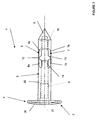
- FIGS. 1 and 2 show a monoblock suture anchor 1 comprising a hollow cylindrical body 2 of elongated shape that can deform plastically and can be put in place on the operating site under arthroscopy.
- the body 2 is constituted at one of its ends by a head 3 comprising means of attachment 4 of the soft tissues 16 against the bone 17 of a patient by via one or more sutures 5 crimped on said head.
- the head 3 consists of the fixing means 4 which are provided between one face cylindrical support 21 and a cylindrical portion 22.
- the cylindrical portion 22 of the head 3 extends away from the fastening means 4 by at least two attachment branches 6, 7 which are, before deformation, parallel to the longitudinal axis XX 'of the body 2.
- the other end of the body 2 being opposite to that of the head 3, is constituted in the extension of the branches 6 and 7 of a point with a conical profile 8 facilitating the placement of the suture anchor in the bone 17.
- the cylindrical portion 22 of the head 3 has a threaded internal bore 9 which opens on the one hand on the side of the fixing means 4 and on the other hand between the fixing branches 6 and 7.
- the threaded bore 9 is carried by the longitudinal axis XX ' of the body 2.
- the tapered tip 8 has in its internal part a hole threaded blind 10 which opens between the attachment legs 6 and 7 and is worn by the same longitudinal axis XX 'as that of the bore 9.
- the diameter the threaded bore 9 is larger than that of the threaded hole 10.
- the branches 6 and 7 are connected to the head 3 and the tip 8 by primers 11 directed towards the center of the body 2 and which will allow deforming said branches under a traction force.
- branches 6 and 7 respectively have in their middle a primer of folding 12, 13 which is inverted with respect to that 11 so that each branch consists of two identical segments 6a, 6b and 7a, 7b.
- each branch 6 and 7 are provided abutment means 14 integral with the cylindrical portion 22 of the head 3 and which is directed towards the tip profile 8.
- Each stop 14 extends parallel to the longitudinal axis XX 'of the body 2 and has a length that depends on the deformation that is desired get branches 6 and 7.
- the plastic deformation of the branches 6 and 7 is limited by the stops 14 which bear against a face 15 of the tapered tip 8.
- the face 15 is disposed in a plane perpendicular to that bearing the axis XX 'of the body 2.
- the fastening means 4 consist of two opposite tabs 18, 19 and parallel to the longitudinal axis XX 'of the body 2, before their deformation.
- the tongues 18 and 19 define an oblong space 20 which allows the passage, through the surgeon at the operative site, of at least one suture 5.
- the oblong space 20 of the fixing means 4 is positioned so that its direction of greater length is perpendicular to the longitudinal axis XX 'of the body 2 of the suture anchor 1.
- the bearing face 21 joining the tabs 18, 19 opposite the part 22, is pierced with a bore 23, coaxial with the thread 9, and which opens on the one hand outside the body 2 and on the other hand between said tongues to be positioned opposite said threaded bore 9 of said portion cylindrical 22.
- the cylindrical portion 22 of the head 3 has on its outer periphery and between the fastening means 4 and the branches 6, 7 a circular collar 24 forming a bearing abutment of the body 2 against the outer wall of the bone 17, when the introduction of the suture anchor 1 inside the latter ( Figure 2).
- the flange 24 has a conical profile which comes into contact with bone 17 for serve as a stop when the fixing branches 6 and 7 collapse.
- FIG. 3 shows a variant of the suture anchor 1 whose body cylindrical 2 has a head 3 ', different from that 3 described above, in Regarding the means for fixing 4 soft tissues.
- the head 3 ' consists of a cylindrical portion 22 longer than that described previously and in which is drilled the internal bore and threaded 9. The latter opens on the one hand between the branches 6, 7 and on the other hand outside the body 2 at the level of the fastening means 4 via a coaxial bore 25.
- the internal bore 9 has, along its length, a threaded portion which is shorter than that shown in FIGS. 1 and 2. Furthermore, it is noted in this variant that the threaded portion of the internal bore 9 is remote from the abutments 14 to be at near the fastening means 4, due to the cylindrical portion 22 longer.
- the fastening means 4 are constituted at the end of the cylindrical portion 22 of the head 3 'and opposite the branches 6,7 by a disc 26 which can be shaped to allow retention of soft tissues 16 against bone 17.
- FIGS. 4a to 4d show the various steps for setting up of the suture anchor 1 previously described inside the bone 17 for fixation soft tissue 16.
- FIG. 4a shows the suture anchor 1 provided with its ancillary 27 for setting place which consists, for example, of a rod 28 which passes through the body 2 to screw into the blind hole 10 of the tapered tip 8.
- the rod 28 is secured to a tip 29 which bears against the face 23 of the head 3.
- FIG. 4b represents the suture anchor 1 which is introduced into the site operative through the ancillary 27 and an arthroscopic cannula 30.
- the surgeon proceeds with the placement of the suture threads 5 in the oblong space Fixing means 4, ie before the introduction of the suture anchor 1 into the operative site, after its placement in bone 17.
- the establishment of the suture anchor 1 in the bone 17 is carried out either by force, either by rotation or by means of a pre-hole pierced in the cortical bone 31 and the cancellous bone 32, through the soft tissue 16 to reinsert.
- FIG. 4c shows the deformation of the suture anchor 1 and more particularly branches 6 and 7 inside the cancellous bone 32 when a traction force T is subjected to the rod 28 of the ancillary 27.
- the rod 28 moves horizontally along the axis XX 'of the body 2, while the tip 29 remains fixed in support against the face 23 of the head 3.
- the branches 6 and 7 deform under a compression force due to the traction T subjected to the rod 28 of the ancillary 27, according to the profile of the primers 11, 12 and 13 so that the segments 6a, 6b and 7a, 7b are directed to the outside of the body 2 and in a direction substantially perpendicular to the axis XX '.
- fixation of the suture anchor 1 in the cancellous bone 32 is performed by the deformation of the branches 6 and 7 until the segments 6a and 7a come into contact with the inner surface of the cortical bone 31.
- FIG. 4d illustrates the crimping of the suture threads 5 on the head 3 of the anchor 1 by through the fastening means 4.
- the tapered tip 8 being in contact with the abutments 14, it is possible to apply a traction force T1 greater than that T on the rod 28 of the ancillary 27, without the risk of breaking the branches 6 and 7, in order to deform the tongues 18 and 19 of the fastening means 4.
- the deformation of the tongues 18 and 19 makes it possible to reduce the oblong space 20 of so as to lock in a stretched position the suture threads 5 on the head 3 of the suture anchor 1.
- the tongues 18 and 19 are shaped so as not to cut the sutures 5 when crimping these on the head 3.
- Sutures 5 allow surgeons to ligate soft tissue 16 over the suture anchor 1.
- FIGS. 5a to 5d show the various steps for setting up of the suture anchor 1 previously described in FIG. 3 inside the bone 17 for fixation of soft tissues 16.
- FIG. 5a shows the suture anchor 1 provided with its ancillary device 27. place which consists of the rod 28 which passes through the body 2 to screw itself in the blind hole 10 of the tapered tip 8.
- the rod 28 is integral with a tip 29 which bears against the disk 26 of the head 3 '.
- Figure 5b shows the suture anchor 1 which is introduced into the site operative through the ancillary 27 and an arthroscopy cannula 34.
- the establishment of the suture anchor 1 in the bone 17 is carried out either by force, either by rotation or by means of a pre-hole pierced in the cortical bone 31 and the cancellous bone 32, through the soft tissue 16 to reinsert.
- FIG. 5c shows the deformation of the suture anchor 1 and more particularly branches 6 and 7 inside the cancellous bone 32 when a traction force T is subjected to the rod 28 of the ancillary 27.
- the rod 28 moves horizontally along the axis XX 'of the body 2, while the tip 29 remains fixed in support against the disk 26 of the head 3 '.
- the branches 6 and 7 deform under a compression force due to the traction T subjected to the rod 28 of the ancillary 27, according to the profile of the primers 11, 12 and 13 so that the segments 6a, 6b and 7a, 7b are directed to the outside of the body 2 and in a direction substantially perpendicular to the axis XX '.
- fixation of the suture anchor 1 in the cancellous bone 32 is performed by the deformation of the branches 6 and 7 until the segments 6a and 7a come into contact with the inner surface of the cortical bone 31.
- FIG. 5d shows the conformation of the disc 26 by the tool 33, after withdrawal prior to the tip 29, to apply a new tensile force T2 higher to that T allowing the deformation of the branches 6 and 7.
- T2 effort allows the surgeon to fold the disc 26 of the head 3 'so that it penetrates the soft tissue 16 to press against the cortical bone 31.
- the conformation or the folding of the disk 26 is made in several times. It suffices surgeon to unscrew the rod 28 to position the tool 33 according to another direction, to screw the rod 28 in the hole 10 of the tip 8 and to apply again the traction force T2 to fold the disk 26.
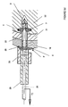
- FIGS. 6a to 6d illustrate the various steps for extracting the anchor from suture 1 of the bone 17 by means of another ancillary tool 35. The latter allows extraction of the suture anchor 1 having the head 3 or 3 '.
- the ancillary 35 comprises a hollow rod 36 which is screwed into the threaded bore 9 of the cylindrical portion 22, while another rod 37 sliding in the first comes to take support in the bottom of the blind hole 10 formed in the tip conical profile 8 ( Figure 6b).
- the rod 36 is subjected to a thrust force P parallel to the axis XX 'of the body 2, to unfold the branches 6 and 7 (Figure 6c).
- the profile of primers 11, 12 and 13 allows to bring back the suture anchor 1 in a shape similar to that original.
- the surgeon can, at using the ancillary 35, remove said anchor from the bone 17, without having to drill a hole whose diameter is substantially similar to that affected by the branches distorted.
Abstract
Description
La présente invention est relative à une ancre de suture permettant de rattacher des tissus mous tels que des ligaments ou tendons à l'os, et principalement pour la réparation de la coiffe des rotateurs et des lésions de Bankart.The present invention relates to a suture anchor for reattaching soft tissues such as ligaments or tendons to the bone, and mainly to repair of rotator cuff and Bankart lesions.
On connaít d'après le brevet américain n° 5 501 695 au nom de Anspach une ancre de suture en deux parties permettant la réinsertion musculaire et tendineuse sur l'os.It is known from United States Patent No. 5,501,695 in the name of Anspach two-part suture anchor for muscle re-insertion and tendonous on the bone.
Cette ancre de suture comprend un premier élément extérieur cylindrique solidaire de branches de fixation qui sont séparées les unes des autres par des fentes disposées parallèlement à l'axe longitudinal de l'ancre de suture. Le premier élément reçoit dans sa partie interne un second élément de déformation qui coopère avec l'extrémité libre des branches de fixation.This suture anchor comprises a first integral cylindrical outer member fastening legs which are separated from one another by slots arranged parallel to the longitudinal axis of the suture anchor. The first element receives in its internal part a second deformation element which cooperates with the free end of the attachment branches.
Le second élément de déformation est solidaire par l'intermédiaire d'une zone de rupture d'une tige de traction qui permet au chirurgien, après avoir introduit l'ancre de suture dans un trou préalablement ménagé dans l'os, de faire coulisser ledit second élément à l'intérieur du premier afin de déformer axialement les branches de fixation dans la partie de l'os spongieux.The second deformation element is secured by means of a zone of rupture of a traction rod which allows the surgeon, after having introduced the anchor suture in a hole previously made in the bone, to slide said second element inside the first to axially deform the branches fixation in the part of the cancellous bone.
Lorsque l'effort de traction est suffisant pour déformer les branches de fixation la tige se sépare du second élément par une rupture irréversible.When the tensile force is sufficient to deform the fastening legs the stem separates from the second element by an irreversible rupture.
On note que les branches se déforment latéralement suivant une direction sensiblement perpendiculaire à l'axe longitudinal de l'ancre de suture pour fixer définitivement cette dernière à l'intérieur de l'os.It is noted that the branches deform laterally in one direction substantially perpendicular to the longitudinal axis of the suture anchor to fix definitely this last inside the bone.
Enfin, le premier élément est solidaire à l'une de ses extrémités d'une collerette qui vient en appui contre l'os cortical et qui est percée d'un certain nombre de trous pour la fixation par le chirurgien de fils de suture.Finally, the first element is integral at one of its ends with a collar which bears against the cortical bone and is pierced by a certain number of holes for fixation by the surgeon of sutures.
L'ancre de suture décrite ci-dessus comporte certains inconvénients à savoir qu'elle n'est pas prévue pour être retirée de l'os sans provoquer une destruction complète de cette dernière et de l'os dans laquelle elle est fixée. En effet l'ancre de suture ne comporte aucun moyen de reprise permettant son retrait de l'os sans engager une détérioration de ce dernier.The suture anchor described above has some drawbacks namely that it is not intended to be removed from the bone without causing destruction complete of the latter and the bone in which it is fixed. Indeed the anchor suture does not include any means of recovery allowing its removal from the bone without engage in deterioration of the latter.
En outre, l'ancre de suture ne comporte pas en dehors de la zone de rupture du second élément, des moyens limitant la course dudit élément pour éviter que les branches de fixation viennent à se rompre anormalement sous l'effort de traction. In addition, the suture anchor does not have outside the rupture zone of the second element, means limiting the stroke of said element to prevent the Fixing branches come to break abnormally under tensile stress.
On connaít également du brevet US 5 649 963, une ancre de suture et un outil sur lequel se visse une douille pour la fixation de ladite ancre.Also known from US Patent 5,649,963, a suture anchor and a tool on which is screwed a socket for fixing said anchor.
L'ancre de suture comporte des moyens d'expansion qui s'écarte en direction de l'extérieur sous la pression de la douille et de l'outil. On note que l'outil présente un dispositif qui permet de rapprocher les moyens d'expansion pour l'extraction de l'ancre de suture.The suture anchor has expansion means which deviates towards outside under the pressure of the socket and the tool. We note that the present tool a device which makes it possible to bring the expansion means closer together for the extraction of the suture anchor.
On constate que l'ancre de suture ne comporte pas de moyens de butée limitant la déformation des moyens d'expansion lors de l'application de la pression de la douille et de l'outil.It can be seen that the suture anchor does not have limiting abutment means the deformation of the expansion means during the application of the pressure of the socket and tool.
On connaít d'après le document US 5 472 452, une ancre de suture comportant des moyens d'expansion à déformation élastique, et un dispositif de déformation guidé à l'intérieur du corps creux de ladite ancre pour déformer les moyens d'expansion.It is known from US 5 472 452, a suture anchor comprising expansion means with elastic deformation, and a deformation device guided inside the hollow body of said anchor to deform the means expansion.
Le dispositif de déformation présente un profil particulier permettant sous un effort de traction de déformer les moyens d'expansion élastique afin qu'ils pénètrent à l'intérieur de l'os spongieux qui se trouve au voisinage du trou dans lequel est préalablement introduit l'ancre de suture.The deformation device has a particular profile allowing under an effort of traction to deform the elastic expansion means so that they penetrate to the interior of the spongy bone that is in the vicinity of the hole in which is previously introduced the suture anchor.
Le dispositif de déformation présente un profil particulier permettant aux moyens d'expansion d'être bloqués dans une position qui retient l'ancre de suture dans l'os spongieux.The deformation device has a particular profile allowing the means of expansion to be locked in a position that holds the suture anchor in spongy bone.
Lors d'un effort de poussée, le dispositif de déformation pénètre à l'intérieur du corps de l'ancre de suture pour déformer à nouveau les moyens d'expansion dans une direction identique à celle de l'effort de traction.During a pushing force, the deformation device penetrates inside the body of the suture anchor to deform again the means of expansion in a direction identical to that of the traction force.
On constate que lors du retrait de l'ancre de suture, les moyens d'expansion pénètrent plus profondément à l'intérieur de l'os spongieux, risquant d'empêcher le retour des moyens d'expansion dans leur position d'origine qui est obtenue du fait des caractéristiques élastiques desdits moyens d'expansion.It is found that during removal of the suture anchor, the means of expansion penetrate deeper into the spongy bone, which may prevent the return of the expansion means to their original position which is obtained from the makes elastic characteristics of said expansion means.
On connaít d'après le document GB 2 173 565 une vis chirurgicale constituée de
plusieurs pièces coopérant intimement ensemble pour permettre la déformation
de moyens d'expansion réalisés dans une matière plastique à haute densité.It is known from
La vis chirurgicale comporte un corps creux et cylindrique traversé par un élément fileté pourvu d'une tête, d'un écrou de serrage coopérant avec l'élément fileté, et des moyens d'expansion prévus entre le corps cylindrique et la tête de l'écrou de serrage.The surgical screw comprises a hollow and cylindrical body traversed by an element threaded head having a head, a clamping nut cooperating with the threaded element, and expansion means provided between the cylindrical body and the head of the nut of Tightening.
Lors de l'entraínement en rotation de l'élément fileté, l'écrou pénètre à l'intérieur du corps creux afin de déformer les moyens d'expansion qui sont collés à la tête dudit écrou.When driving in rotation of the threaded element, the nut penetrates inside of the hollow body in order to deform the expansion means which are glued to the head said nut.
On note que la vis décrite dans le brevet GB 2 173 565 n'est pas monobloc, c'est
à dire réalisée d'une seule pièce, et que les moyens d'expansion ne présentent
pas de caractéristiques de déformation plastique du fait de la matière utilisée. It is noted that the screw described in
C'est à ces inconvénients qu'entend plus particulièrement remédier la présente invention.It is to these drawbacks that the present invention.
L'ancre de suture suivant la présente invention à pour objet d'être réversible pour permettre son extraction de l'os sans avoir à percer un trou à un diamètre plus grand que celui des branches déformées.The suture anchor according to the present invention is intended to be reversible for allow the bone to be removed without having to drill a hole at a larger diameter large than that of deformed branches.
L'ancre de suture suivant la présente invention permettant la fixation de tissus mous contre un os, comporte un corps creux comprenant à l'une de ses extrémités une tête pourvue de moyens de fixation des tissus mous contre l'os par le passage d'au moins un fil de suture, lesdits moyens de fixation sont constitués de deux languettes opposées et parallèles à l'axe longitudinal (XX') du corps creux, avant déformation, afin de délimiter un espace oblong qui est traversé par au moins un fil de suture, ledit fil de suture étant serti sur la tête après déformation des languettes sous un effort de traction pour permettre la ligature des tissus mous sur l'ancre de suture.The suture anchor according to the present invention for fixing tissue soft against a bone, has a hollow body comprising at one of its extremities a head provided with soft tissue fixation means against the bone by the passage of at least one suture, said fixing means are constituted two tabs opposite and parallel to the longitudinal axis (XX ') of the body hollow, before deformation, in order to delimit an oblong space which is traversed by at least one suture, said suture being crimped onto the head after deformation tongues under tensile stress to allow tissue ligation soft on the suture anchor.
L'ancre de suture suivant la présente invention comporte un corps creux comprenant des moyens d'expansion réversibles qui sont constitués par au moins deux branches de fixation disposées dans le prolongement de ladite tête et parallèlement à l'axe longitudinal (XX') dudit corps avant déformation, au moins deux butées intercalées entre chaque branche de fixation et limitant la déformation plastique de ces dernières lors de l'application d'un effort extérieur de traction (T) pour la fixation de l'ancre de suture dans l'os afin que la déformation desdits moyens d'expansion soit réversible lors de l'application d'un autre effort extérieur de poussée (P) permettant le retrait de ladite ancre de suture de l'os.The suture anchor according to the present invention comprises a hollow body comprising reversible expansion means which consist of at least two fixing branches arranged in the extension of said head and parallel to the longitudinal axis (XX ') of said body before deformation, at least two stops interposed between each fixing branch and limiting the plastic deformation of the latter when applying an external force of traction (T) for fixation of the suture anchor in the bone so that deformation said expansion means is reversible upon application of another effort external pusher (P) for removing said suture anchor from the bone.
L'ancre de suture suivant la présente invention comporte un corps creux comprenant une pointe à profil conique dans laquelle est ménagée un trou borgne fileté qui est prévu pour recevoir une tige filetée d'un ancillaire pour déformer, d'une part sous un premier effort de traction (T) les branches de fixation suivant une direction sensiblement perpendiculaire à l'axe longitudinal (XX') dudit corps et d'autre part sous un second effort de traction (T1, T2) supérieur au premier (T) les moyens de fixation.The suture anchor according to the present invention comprises a hollow body comprising a tapered tip in which a blind hole is formed threaded which is provided to receive a threaded rod of an ancillary to deform, firstly under a first traction force (T) the following fixing branches a direction substantially perpendicular to the longitudinal axis (XX ') of said body and on the other hand under a second traction force (T1, T2) greater than the first (T) the fastening means.
L'ancre de suture suivant la présente invention comporte un corps creux comprenant à proximité de la tête un alésage interne fileté qui est destiné à recevoir une première tige filetée creuse d'un ancillaire, tandis qu'une seconde tige coulissant dans la première tige vient en appui dans le fond d'un trou borgne fileté pour déplier sous un effort de poussée (P) les branches de fixation dans une position sensiblement allongée pour pouvoir extraire l'ancre de suture de l'os.The suture anchor according to the present invention comprises a hollow body comprising near the head a threaded internal bore which is intended for receive a first hollow threaded rod of an ancillary, while a second sliding rod in the first rod comes to rest in the bottom of a blind hole threaded to unfold under a thrust force (P) the attachment branches in a substantially elongate position to extract the suture anchor from the bone.
L'ancre de suture suivant la présente invention comporte des branches de fixation qui sont raccordées à une partie cylindrique de la tête et à la pointe à profil conique par des premières amorces de pliage dirigées en direction du centre du corps.The suture anchor according to the present invention comprises fixation branches which are connected to a cylindrical part of the head and to the profile tip tapered by first bending primers directed towards the center of the body.
L'ancre de suture suivant la présente invention comporte des branches de fixation qui présentent respectivement en leur milieu une seconde amorce de pliage qui est inversée par rapport aux premières amorces de pliage de manière que chaque branche soit constituée de deux segments identiques.The suture anchor according to the present invention comprises fixation branches which respectively have in their middle a second folding starter which is reversed compared to the first folding primers so that each branch consists of two identical segments.
L'ancre de suture suivant la présente invention comporte un alésage interne fileté et un trou borgne fileté qui sont portés par le même axe longitudinal (XX') du corps et sont prévus de diamètres différents.The suture anchor according to the present invention has a threaded internal bore and a threaded blind hole which are carried by the same longitudinal axis (XX ') of the body and are provided of different diameters.
L'ancre de suture suivant la présente invention comporte des butées qui s'étendent parallèlement à l'axe longitudinal (XX') du corps et présentent une longueur qui dépend de la déformation que l'on désire obtenir des branches de fixation.The suture anchor according to the present invention has stops which extend parallel to the longitudinal axis (XX ') of the body and have a length which depends on the deformation that one desires to obtain branches of fixation.
L'ancre de suture suivant la présente invention comporte des moyens de fixation dont l'espace oblong est positionné de manière que sa direction de plus grande longueur soit perpendiculaire à l'axe longitudinal (XX') du corps.The suture anchor according to the present invention comprises fixing means whose oblong space is positioned so that its direction of larger length is perpendicular to the longitudinal axis (XX ') of the body.
L'ancre de suture suivant la présente invention comporte une tête comprenant une partie cylindrique pourvue sur sa périphérie externe d'une collerette circulaire formant une butée d'appui du corps contre la paroi externe de l'os.The suture anchor according to the present invention comprises a head comprising a cylindrical portion provided on its outer periphery with a circular collar forming a bearing abutment of the body against the outer wall of the bone.
La description qui va suivre en regard des dessins annexés, donnés à titre
d'exemples non limitatifs, permettra de mieux comprendre l'invention, les
caractéristiques qu'elle présente et les avantages qu'elle est susceptible de
procurer :
On a montré en figures 1 et 2 une ancre de suture monobloc 1 comportant un
corps cylindrique creux 2 de forme allongée susceptible de se déformer
plastiquement et pouvant être mis en place sur le site opératoire sous
arthroscopie.FIGS. 1 and 2 show a
Le corps 2 est constitué à l'une de ses extrémités d'une tête 3 comportant des
moyens de fixation 4 des tissus mous 16 contre l'os 17 d'un patient par
l'intermédiaire d'un ou plusieurs fils de suture 5 sertis sur ladite tête. The
La tête 3 est constituée des moyens de fixation 4 qui sont prévus entre une face
cylindrique d'appui 21 et une partie cylindrique 22.The
La partie cylindrique 22 de la tête 3 se prolonge à l'opposé des moyens de fixation
4 par au moins deux branches de fixation 6, 7 qui sont, avant déformation,
parallèles à l'axe longitudinal XX' du corps 2.The
L'autre extrémité du corps 2, se trouvant à l'opposé de celle de la tête 3, est
constituée dans le prolongement des branches 6 et 7 d'une pointe à profil conique
8 facilitant la mise en place de l'ancre de suture dans l'os 17.The other end of the
La partie cylindrique 22 de la tête 3 comporte un alésage interne fileté 9 qui
débouche d'une part du coté des moyens de fixation 4 et d'autre part entre les
branches de fixation 6 et 7. L'alésage fileté 9 est porté par l'axe longitudinal XX'
du corps 2.The
Également, la pointe à profil conique 8 présente dans sa partie interne un trou
borgne fileté 10 qui débouche entre les branches de fixation 6 et 7 et qui est porté
par le même axe longitudinal XX' que celui de l'alésage 9. En Outre, le diamètre
de l'alésage fileté 9 est prévu plus grand que celui du trou fileté 10.Also, the
Les branches 6 et 7 sont raccordées à la tête 3 et à la pointe 8 par des amorces
de pliage 11 dirigées en direction du centre du corps 2 et qui permettront de
déformer lesdites branches sous un effort de traction.The
Les branches 6 et 7 présentent respectivement en leur milieu une amorce de
pliage 12, 13 qui est inversée par rapport à celle 11 de manière que chaque
branche soit constituée de deux segments identiques 6a, 6b et 7a, 7b.The
Entre chaque branche 6 et 7 sont prévus des moyens de butée 14 solidaires de la
partie cylindrique 22 de la tête 3 et qui est dirigée en direction de la pointe à profil
conique 8. Chaque butée 14 s'étend parallèlement à l'axe longitudinal XX' du
corps 2 et présente une longueur qui dépend de la déformation que l'on désire
obtenir des branches 6 et 7.Between each
En effet, la déformation plastique des branches 6 et 7 est limitée par les butées 14
qui viennent en appui contre une face 15 de la pointe à profil conique 8. La face
15 est disposée dans un plan perpendiculaire à celui portant l'axe XX' du corps 2.Indeed, the plastic deformation of the
Les moyens de fixation 4 sont constitués de deux languettes 18, 19 opposées et
parallèles à l'axe longitudinal XX' du corps 2, avant leur déformation. Les
languettes 18 et 19 délimitent un espace oblong 20 qui permet le passage, par le
chirurgien sur le site opératoire, d'au moins un fil de suture 5.The fastening means 4 consist of two
L'espace oblong 20 des moyens de fixation 4, est positionné de manière que sa
direction de plus grande longueur soit perpendiculaire à l'axe longitudinal XX' du
corps 2 de l'ancre de suture 1.The
La face d'appui 21 réunissant les languettes 18, 19 à l'opposé de la partie
cylindrique 22, est percée d'un alésage 23, coaxial à celui fileté 9, et qui
débouche d'une part à l'extérieur du corps 2 et d'autre part entre lesdites
languettes pour être positionné en face dudit alésage fileté 9 de ladite partie
cylindrique 22.The bearing face 21 joining the
La partie cylindrique 22 de la tête 3 comporte sur sa périphérie externe et entre
les moyens de fixation 4 et les branches 6, 7 une collerette circulaire 24 formant
une butée d'appui du corps 2 contre la paroi externe de l'os 17, lors de
l'introduction de l'ancre de suture 1 à l'intérieur de ce dernier (figure 2). La
collerette 24 présente un profil conique qui vient en contact avec l'os 17 pour
servir de butée lors de l'effondrement des branches de fixation 6 et 7.The
En figure 3 on a représenté une variante de l'ancre de suture 1 dont le corps
cylindrique 2 présente une tête 3', différente de celle 3 décrite précédemment, en
ce qui concerne les moyens de fixation 4 des tissus mous.FIG. 3 shows a variant of the
La tête 3' est constituée d'une partie cylindrique 22 plus longue que celle décrite
précédemment et dans laquelle est percé l'alésage interne et fileté 9. Ce dernier
débouche d'une part entre les branches 6, 7 et d'autre part à l'extérieur du corps 2
au niveau des moyens de fixation 4 par l'intermédiaire d'un alésage coaxial 25.The head 3 'consists of a
L'alésage interne 9 présente, sur sa longueur, une partie filetée qui est plus courte
que celle montrée en figures 1 et 2. De plus, on remarque dans cette variante que
la partie filetée de l'alésage interne 9 est éloignée des butées 14 pour se trouver à
proximité des moyens de fixation 4, du fait de la partie cylindrique 22 plus longue.The
Les moyens de fixation 4 sont constitués à l'extrémité de la partie cylindrique 22
de la tête 3' et à l'opposé des branches 6,7 par un disque 26 qui peut être
conformé pour permettre la retenue des tissus mous 16 contre l'os 17.The fastening means 4 are constituted at the end of the
On a représenté en figures 4a à 4d les différentes étapes pour la mise en place
de l'ancre de suture 1 décrite précédemment à l'intérieur de l'os 17 pour la fixation
des tissus mous 16.FIGS. 4a to 4d show the various steps for setting up
of the
La figure 4a montre l'ancre de suture 1 munie de son ancillaire 27 de mise en
place qui est constitué, par exemple, d'une tige 28 qui traverse le corps 2 pour
venir se visser dans le trou borgne 10 de la pointe à profil conique 8. La tige 28
est solidaire d'un embout 29 qui vient prendre appui contre la face 23 de la tête 3.FIG. 4a shows the
La figure 4b représente l'ancre de suture 1 qui est introduite dans le site
opératoire par l'intermédiaire de l'ancillaire 27 et d'une canule d'arthroscopie 30.
Le chirurgien procède à la mise en place des fils de suture 5 dans l'espace oblong
20 des moyens de fixation 4, soit avant l'introduction de l'ancre de suture 1 dans
le site opératoire, soit après sa mise en place dans l'os 17.FIG. 4b represents the
La mise en place de l'ancre de suture 1 dans l'os 17 est réalisée soit par force,
soit par rotation, soit par l'intermédiaire d'un pré-trou percé dans l'os cortical 31 et
l'os spongieux 32, à travers le tissu mou 16 à réinsérer.The establishment of the
La figure 4c montre la déformation de l'ancre de suture 1 et plus particulièrement
des branches 6 et 7 à l'intérieur de l'os spongieux 32 lorsqu'un effort de traction T
est soumis à la tige 28 de l'ancillaire 27. Ainsi, la tige 28 se déplace
horizontalement suivant l'axe XX' du corps 2, tandis que l'embout 29 reste fixe en
appui contre la face 23 de la tête 3.FIG. 4c shows the deformation of the
La déformation des branches 6 et 7 est limitée jusqu'à ce que la pointe à profil
conique 8 vienne par l'intermédiaire de sa paroi 15 en appui contre les butées 14.The deformation of the
Les branches 6 et 7 se déforment, sous un effort de compression du fait de la
traction T soumise à la tige 28 de l'ancillaire 27, suivant le profil des amorces 11,
12 et 13 de manière que les segments 6a, 6b et 7a, 7b soient dirigés à l'extérieur
du corps 2 et dans une direction sensiblement perpendiculaire à l'axe XX'.The
On note que la fixation de l'ancre de suture 1 dans l'os spongieux 32 est réalisée
par la déformation des branches 6 et 7 jusqu'à ce que les segments 6a et 7a
viennent en contact avec la face interne de l'os cortical 31.It is noted that the fixation of the
La figure 4d illustre le sertissage des fils de suture 5 sur la tête 3 de l'ancre 1 par
l'intermédiaire des moyens de fixation 4.FIG. 4d illustrates the crimping of the
La pointe à profil conique 8 étant en contact avec les butées 14, il est possible
d'appliquer un effort de traction T1 plus important que celui T sur la tige 28 de
l'ancillaire 27, sans risquer de rompre les branches 6 et 7, afin de déformer les
languettes 18 et 19 des moyens de fixation 4.The tapered
La déformation des languettes 18 et 19 permet de réduire l'espace oblong 20 de
manière à bloquer dans une position tendue les fils de suture 5 sur la tête 3 de
l'ancre de suture 1.The deformation of the
Les languettes 18 et 19 sont conformées pour ne pas couper les fils de suture 5
lors du sertissage de ces derniers sur la tête 3.The
Les fils de suture 5 permettent aux chirurgiens de ligaturer les tissus mous 16 sur
l'ancre de suture 1.
On a représenté en figures 5a à 5d les différentes étapes pour la mise en place
de l'ancre de suture 1 décrite précédemment en figure 3 à l'intérieur de l'os 17
pour la fixation des tissus mous 16.FIGS. 5a to 5d show the various steps for setting up
of the
La figure 5a montre l'ancre de suture 1 munie de son ancillaire 27 de mise en
place qui est constitué de la tige 28 qui traverse le corps 2 pour venir se visser
dans le trou borgne 10 de la pointe à profil conique 8. La tige 28 est solidaire d'un
embout 29 qui vient prendre appui contre le disque 26 de la tête 3'.FIG. 5a shows the
Autour de l'embout 29 est prévu un outil de mise en forme 33 du disque 26 sur le
tissu mou 16.Around the
La figure 5b représente l'ancre de suture 1 qui est introduite dans le site
opératoire par l'intermédiaire de l'ancillaire 27 et d'une canule d'arthroscopie 34.Figure 5b shows the
La mise en place de l'ancre de suture 1 dans l'os 17 est réalisée soit par force,
soit par rotation, soit par l'intermédiaire d'un pré-trou percé dans l'os cortical 31 et
l'os spongieux 32, à travers le tissu mou 16 à réinsérer. The establishment of the
La figure 5c montre la déformation de l'ancre de suture 1 et plus particulièrement
des branches 6 et 7 à l'intérieur de l'os spongieux 32 lorsqu'un effort de traction T
est soumis à la tige 28 de l'ancillaire 27. Ainsi, la tige 28 se déplace
horizontalement suivant l'axe XX' du corps 2, tandis que l'embout 29 reste fixe en
appui contre le disque 26 de la tête 3'.FIG. 5c shows the deformation of the
La déformation des branches 6 et 7 est limitée jusqu'à ce que la pointe à profil
conique 8 vienne par l'intermédiaire de sa face 15 en appui contre les butées 14.The deformation of the
Les branches 6 et 7 se déforment, sous un effort de compression du fait de la
traction T soumise à la tige 28 de l'ancillaire 27, suivant le profil des amorces 11,
12 et 13 de manière que les segments 6a, 6b et 7a, 7b soient dirigés à l'extérieur
du corps 2 et dans une direction sensiblement perpendiculaire à l'axe XX'.The
On note que la fixation de l'ancre de suture 1 dans l'os spongieux 32 est réalisée
par la déformation des branches 6 et 7 jusqu'à ce que les segments 6a et 7a
viennent en contact avec la face interne de l'os cortical 31.It is noted that the fixation of the
En figure 5d on a montré la conformation du disque 26 par l'outil 33, après retrait
préalable de l'embout 29, afin d'appliquer un nouvel effort de traction T2 supérieur
à celui T permettant la déformation des branches 6 et 7.FIG. 5d shows the conformation of the
L'effort T2 permet au chirurgien de plier le disque 26 de la tête 3' pour qu'il
pénètre dans le tissu mou 16 afin de le plaquer contre l'os cortical 31.T2 effort allows the surgeon to fold the
La conformation ou le pliage du disque 26 est réalisé en plusieurs fois. Il suffit au
chirurgien de dévisser la tige 28 pour positionner l'outil 33 suivant une autre
direction, de revisser la tige 28 dans le trou 10 de la pointe 8 et d'appliquer de
nouveau l'effort de traction T2 pour plier le disque 26.The conformation or the folding of the
En figures 6a à 6d on a illustré les différentes étapes pour extraire l'ancre de
suture 1 de l'os 17 au moyen d'un autre ancillaire 35. Ce dernier permet
l'extraction de l'ancre de suture 1 comportant la tête 3 ou 3'.FIGS. 6a to 6d illustrate the various steps for extracting the anchor from
L'ancillaire 35 comporte une tige creuse 36 qui vient se visser dans l'alésage fileté
9 de la partie cylindrique 22, tandis qu'une autre tige 37 coulissant dans la
première vient prendre appui dans le fond du trou borgne 10 ménagé dans la
pointe à profil conique 8 (figure 6b).The ancillary 35 comprises a
La tige 36 est soumise à un effort de poussée P parallèle à l'axe XX' du corps 2,
afin de déplier les branches 6 et 7 (figure 6c). Le profil des amorces 11, 12 et 13
permet de ramener l'ancre de suture 1 suivant une forme semblable à celle
d'origine.The
Dès que l'ancre de suture 1 a retrouvé une position allongée, le chirurgien peut, à
l'aide de l'ancillaire 35, retirer ladite ancre de l'os 17, sans avoir à percer un trou
dont le diamètre est sensiblement voisin de celui affecté par les branches
déformées.As soon as the
Claims (10)
Applications Claiming Priority (3)
| Application Number | Priority Date | Filing Date | Title |
|---|---|---|---|
| FR9805203A FR2777442B1 (en) | 1998-04-21 | 1998-04-21 | REVERSIBLE EXPANSION SUTURE ANCHOR |
| FR9805203 | 1998-04-21 | ||
| EP99914634A EP1073374B1 (en) | 1998-04-21 | 1999-04-21 | Suture anchor with reversible expansion |
Related Parent Applications (1)
| Application Number | Title | Priority Date | Filing Date |
|---|---|---|---|
| EP99914634A Division EP1073374B1 (en) | 1998-04-21 | 1999-04-21 | Suture anchor with reversible expansion |
Publications (2)
| Publication Number | Publication Date |
|---|---|
| EP1532930A1 true EP1532930A1 (en) | 2005-05-25 |
| EP1532930B1 EP1532930B1 (en) | 2006-11-29 |
Family
ID=9525671
Family Applications (2)
| Application Number | Title | Priority Date | Filing Date |
|---|---|---|---|
| EP04029007A Expired - Lifetime EP1532930B1 (en) | 1998-04-21 | 1999-04-21 | Suture anchor with reversible expansion |
| EP99914634A Expired - Lifetime EP1073374B1 (en) | 1998-04-21 | 1999-04-21 | Suture anchor with reversible expansion |
Family Applications After (1)
| Application Number | Title | Priority Date | Filing Date |
|---|---|---|---|
| EP99914634A Expired - Lifetime EP1073374B1 (en) | 1998-04-21 | 1999-04-21 | Suture anchor with reversible expansion |
Country Status (6)
| Country | Link |
|---|---|
| US (1) | US6328758B1 (en) |
| EP (2) | EP1532930B1 (en) |
| DE (2) | DE69934267T2 (en) |
| ES (2) | ES2241274T3 (en) |
| FR (1) | FR2777442B1 (en) |
| WO (1) | WO1999053844A1 (en) |
Cited By (2)
| Publication number | Priority date | Publication date | Assignee | Title |
|---|---|---|---|---|
| CN103758835A (en) * | 2013-09-13 | 2014-04-30 | 徐宝余 | Suspension type detachable bearizing anchor bolt |
| CN103807259B (en) * | 2013-09-13 | 2016-08-17 | 徐宝余 | A kind of card slot type detachable reaming crab-bolt |
Families Citing this family (236)
| Publication number | Priority date | Publication date | Assignee | Title |
|---|---|---|---|---|
| IL127978A0 (en) | 1999-01-08 | 1999-11-30 | Influence Med Tech Ltd | Incontinence device |
| FR2768613B1 (en) * | 1997-09-23 | 1999-12-17 | Tornier Sa | KNEE PROSTHESIS WITH ROTATABLE PLATFORM |
| FR2777447B1 (en) * | 1998-04-21 | 2000-07-28 | Tornier Sa | REVERSIBLE FIXATION DEVICE FOR PLACING AN IMPLANT IN THE BONE |
| CA2452508C (en) * | 1998-10-26 | 2010-09-14 | Expanding Orthopedics Inc. | Expandable orthopedic device |
| WO2000040158A2 (en) | 1999-01-08 | 2000-07-13 | Influence Medical Technologies, Ltd. | Surgical tack |
| US8821541B2 (en) | 1999-02-02 | 2014-09-02 | Arthrex, Inc. | Suture anchor with insert-molded rigid member |
| US9521999B2 (en) | 2005-09-13 | 2016-12-20 | Arthrex, Inc. | Fully-threaded bioabsorbable suture anchor |
| US8343186B2 (en) | 2004-04-06 | 2013-01-01 | Arthrex, Inc. | Fully threaded suture anchor with transverse anchor pin |
| FR2797178B1 (en) * | 1999-08-05 | 2002-02-22 | Tornier Sa | MALLEOLAR IMPLANT FOR PARTIAL OR TOTAL ANKLE PROSTHESIS AND ANCILLARY MATERIAL FOR PLACING SUCH AN IMPLANT |
| US6524317B1 (en) | 1999-12-30 | 2003-02-25 | Opus Medical, Inc. | Method and apparatus for attaching connective tissues to bone using a knotless suture anchoring device |
| US6638239B1 (en) | 2000-04-14 | 2003-10-28 | Glaukos Corporation | Apparatus and method for treating glaucoma |
| US6660008B1 (en) | 2001-06-07 | 2003-12-09 | Opus Medical, Inc. | Method and apparatus for attaching connective tissues to bone using a suture anchoring device |
| US6582453B1 (en) | 2000-07-14 | 2003-06-24 | Opus Medical, Inc. | Method and apparatus for attaching connective tissues to bone using a suture anchoring device |
| WO2002005718A2 (en) * | 2000-07-14 | 2002-01-24 | Opus Medical, Inc. | Suture anchor for attaching a suture to a bone part |
| US6585730B1 (en) | 2000-08-30 | 2003-07-01 | Opus Medical, Inc. | Method and apparatus for attaching connective tissues to bone using a knotless suture anchoring device |
| US6520980B1 (en) * | 2000-11-02 | 2003-02-18 | Opus Medical, Inc. | Method and apparatus for attaching connective tissues to bone using a self-locking knotless suture anchoring device |
| US7083638B2 (en) * | 2001-02-12 | 2006-08-01 | Arthrocare Corporation | Method and apparatus for attaching connective tissues to bone using a knotless suture anchoring device |
| US6770076B2 (en) * | 2001-02-12 | 2004-08-03 | Opus Medical, Inc. | Method and apparatus for attaching connective tissues to bone using a knotless suture anchoring device |
| US8657854B2 (en) | 2001-02-12 | 2014-02-25 | Arthrocare Corporation | Knotless suture anchoring device having deforming section to accommodate sutures of various diameters |
| JP4298296B2 (en) | 2001-03-09 | 2009-07-15 | ボストン サイエンティフィック リミテッド | Medical sling |
| US8033983B2 (en) | 2001-03-09 | 2011-10-11 | Boston Scientific Scimed, Inc. | Medical implant |
| US6547800B2 (en) * | 2001-06-06 | 2003-04-15 | Opus Medical, Inc. | Method and apparatus for attaching connective tissues to bone using a cortical bone anchoring device |
| FR2826860B1 (en) * | 2001-07-09 | 2004-03-05 | Tornier Sa | ANCILLARY OF POSITION OF A CUBITAL COMPONENT AND / OR A RADIAL COMPONENT OF ELBOW PROSTHESIS |
| FR2826859B1 (en) * | 2001-07-09 | 2003-09-19 | Tornier Sa | ANCILLARY OF LAYING OF A HUMERAL COMPONENT OF ELBOW PROSTHESIS |
| FR2827500B1 (en) * | 2001-07-17 | 2004-04-02 | Tornier Sa | PLATE OF OSTEOSYNTHESIS OF THE UPPER END OF THE HUMERUS |
| US6780198B1 (en) | 2001-12-06 | 2004-08-24 | Opus Medical, Inc. | Bone anchor insertion device |
| GB0208667D0 (en) | 2002-04-16 | 2002-05-29 | Atlantech Medical Devices Ltd | A transverse suspension device |
| US20040230194A1 (en) * | 2002-06-12 | 2004-11-18 | Urbanski Mark G. | Device and method for attaching soft tissue to bone |
| US20030233095A1 (en) * | 2002-06-12 | 2003-12-18 | Urbanski Mark G. | Device and method for attaching soft tissue to bone |
| FR2848183B1 (en) * | 2002-12-10 | 2006-01-27 | Tornier Sa | STERILE CONDITIONING METHOD OF A POLYETHYLENE PROTHETIC IMPLANT |
| EP1581148B1 (en) | 2002-12-17 | 2010-02-17 | Boston Scientific Limited | Spacer for sling delivery system |
| US8562646B2 (en) * | 2002-12-19 | 2013-10-22 | Boston Scientific Scimed, Inc. | Anchoring to soft tissue |
| FR2850010B1 (en) * | 2003-01-17 | 2005-12-02 | Tornier Sa | ANCILLARY FOR THE INSTALLATION OF A PROTHETIC COTYL FOR A HIP PROSTHESIS |
| US7887544B2 (en) | 2003-03-10 | 2011-02-15 | Tornier Sas | Ancillary tool for positioning a glenoid implant |
| FR2854792B1 (en) * | 2003-05-12 | 2005-09-09 | Tornier Sa | GAME OF PROTHETIC ELEMENTS FOR A TIBIAL PROTHETIC SET |
| FR2855397B1 (en) | 2003-05-28 | 2005-07-15 | Tornier Sa | ELBOW PROSTHESIS |
| US7309355B2 (en) | 2003-06-27 | 2007-12-18 | Depuy Mitek, Inc. | Flexible tibial sheath |
| US7361138B2 (en) | 2003-07-31 | 2008-04-22 | Scimed Life Systems, Inc. | Bioabsorbable casing for surgical sling assembly |
| US7682374B2 (en) | 2003-10-21 | 2010-03-23 | Arthrocare Corporation | Knotless suture lock and bone anchor implant method |
| US20050090827A1 (en) * | 2003-10-28 | 2005-04-28 | Tewodros Gedebou | Comprehensive tissue attachment system |
| FR2863865B1 (en) | 2003-12-19 | 2006-10-06 | Tornier Sa | SHOULDER OR HIP PROSTHESIS AND METHOD OF MOUNTING |
| CA2551531C (en) * | 2003-12-26 | 2015-02-24 | Terumo Kabushiki Kaisha | Tissue closure and tissue closing device |
| US20080195178A1 (en) * | 2003-12-30 | 2008-08-14 | Kuzma Janusz A | Fixation methods and systems for cochlear implant component or other implantable devices |
| CA2552727A1 (en) | 2004-01-16 | 2005-08-04 | Expanding Orthopedics, Inc. | Bone fracture treatment devices |
| EP1729649B1 (en) | 2004-01-16 | 2014-06-25 | Arthrocare Corporation | Bone harvesting device and method |
| FR2865928B1 (en) | 2004-02-10 | 2006-03-17 | Tornier Sa | SURGICAL DEVICE FOR IMPLANTATION OF A TOTAL HIP PROSTHESIS |
| US7608092B1 (en) | 2004-02-20 | 2009-10-27 | Biomet Sports Medicince, LLC | Method and apparatus for performing meniscus repair |
| US7938847B2 (en) * | 2006-01-04 | 2011-05-10 | Tornier, Inc. | Ring cinch assembly to attach bone to tissue |
| US20050245932A1 (en) * | 2004-04-16 | 2005-11-03 | Fanton Gary S | Apparatus and methods for securing tissue to bone |
| WO2005110244A1 (en) * | 2004-05-07 | 2005-11-24 | Usgi Medical Inc. | Apparatus and methods for positioning and securing anchors |
| WO2005112788A2 (en) * | 2004-05-17 | 2005-12-01 | Arthrocare Corporation | Bone anchor |
| WO2006060035A2 (en) | 2004-06-02 | 2006-06-08 | Kfx Medical Corporation | System and method for attaching soft tissue to bone |
| US8062334B2 (en) * | 2004-06-02 | 2011-11-22 | Kfx Medical Corporation | Suture anchor |
| US8303665B2 (en) | 2004-06-15 | 2012-11-06 | Tornier Sas | Glenoidal component, set of such components and shoulder prosthesis incorporating such a glenoidal component |
| FR2871368B1 (en) | 2004-06-15 | 2006-08-25 | Tornier Sas | SET OF HUMERAL COMPONENTS FOR TOTAL SHOULDER PROSTHESIS |
| US7678150B2 (en) | 2004-06-15 | 2010-03-16 | Tornier Sas | Total shoulder prosthesis of an inverted type |
| FR2872025B1 (en) * | 2004-06-28 | 2006-08-25 | Tornier Sas | PROSTHESIS OF SHOULDER OR HIP |
| US9017381B2 (en) | 2007-04-10 | 2015-04-28 | Biomet Sports Medicine, Llc | Adjustable knotless loops |
| US8840645B2 (en) | 2004-11-05 | 2014-09-23 | Biomet Sports Medicine, Llc | Method and apparatus for coupling soft tissue to a bone |
| US8118836B2 (en) | 2004-11-05 | 2012-02-21 | Biomet Sports Medicine, Llc | Method and apparatus for coupling soft tissue to a bone |
| US7909851B2 (en) | 2006-02-03 | 2011-03-22 | Biomet Sports Medicine, Llc | Soft tissue repair device and associated methods |
| US7905903B2 (en) | 2006-02-03 | 2011-03-15 | Biomet Sports Medicine, Llc | Method for tissue fixation |
| US7658751B2 (en) | 2006-09-29 | 2010-02-09 | Biomet Sports Medicine, Llc | Method for implanting soft tissue |
| US8088130B2 (en) | 2006-02-03 | 2012-01-03 | Biomet Sports Medicine, Llc | Method and apparatus for coupling soft tissue to a bone |
| US7749250B2 (en) | 2006-02-03 | 2010-07-06 | Biomet Sports Medicine, Llc | Soft tissue repair assembly and associated method |
| US7857830B2 (en) * | 2006-02-03 | 2010-12-28 | Biomet Sports Medicine, Llc | Soft tissue repair and conduit device |
| US8298262B2 (en) | 2006-02-03 | 2012-10-30 | Biomet Sports Medicine, Llc | Method for tissue fixation |
| US20060189993A1 (en) | 2004-11-09 | 2006-08-24 | Arthrotek, Inc. | Soft tissue conduit device |
| US7905904B2 (en) | 2006-02-03 | 2011-03-15 | Biomet Sports Medicine, Llc | Soft tissue repair device and associated methods |
| US9801708B2 (en) | 2004-11-05 | 2017-10-31 | Biomet Sports Medicine, Llc | Method and apparatus for coupling soft tissue to a bone |
| US8128658B2 (en) | 2004-11-05 | 2012-03-06 | Biomet Sports Medicine, Llc | Method and apparatus for coupling soft tissue to bone |
| US8361113B2 (en) | 2006-02-03 | 2013-01-29 | Biomet Sports Medicine, Llc | Method and apparatus for coupling soft tissue to a bone |
| US8137382B2 (en) | 2004-11-05 | 2012-03-20 | Biomet Sports Medicine, Llc | Method and apparatus for coupling anatomical features |
| US8303604B2 (en) | 2004-11-05 | 2012-11-06 | Biomet Sports Medicine, Llc | Soft tissue repair device and method |
| US8034090B2 (en) | 2004-11-09 | 2011-10-11 | Biomet Sports Medicine, Llc | Tissue fixation device |
| US8998949B2 (en) | 2004-11-09 | 2015-04-07 | Biomet Sports Medicine, Llc | Soft tissue conduit device |
| US7914539B2 (en) | 2004-11-09 | 2011-03-29 | Biomet Sports Medicine, Llc | Tissue fixation device |
| WO2006055516A2 (en) * | 2004-11-15 | 2006-05-26 | Scandius Biomedical, Inc. | Method and apparatus for the repair of a rotator cuff (rtc) tendon or ligament |
| US7144415B2 (en) * | 2004-11-16 | 2006-12-05 | The Anspach Effort, Inc. | Anchor/suture used for medical procedures |
| AU2005306450B9 (en) * | 2004-11-18 | 2012-02-02 | Cayenne Medical, Inc. | Devices, systems and methods for material fixation |
| US20090132047A1 (en) * | 2004-11-30 | 2009-05-21 | Mansmann Kevin A | Anchoring systems and interfaces for flexible surgical implants for replacing cartilage |
| US8986345B2 (en) | 2004-12-07 | 2015-03-24 | Biomet Sports Medicine, Llc | Expanding suture anchor having an actuator pin |
| US7976565B1 (en) * | 2004-12-07 | 2011-07-12 | Biomet Sports Medicine, Llc | Expanding suture anchor having an actuator pin |
| US7572283B1 (en) * | 2004-12-07 | 2009-08-11 | Biomet Sports Medicine, Llc | Soft tissue rivet and method of use |
| FR2881340B1 (en) * | 2005-02-01 | 2008-01-11 | Tornier Sas | HUMERAL NUTS |
| US8882787B2 (en) * | 2005-03-02 | 2014-11-11 | St. Jude Medical, Cardiology Division, Inc. | Tissue anchor apparatus |
| FR2884407B1 (en) * | 2005-04-13 | 2007-05-25 | Tornier Sas | SURGICAL DEVICE FOR IMPLANTATION OF A PARTIAL OR TOTAL KNEE PROSTHESIS |
| FR2884408B1 (en) * | 2005-04-13 | 2007-05-25 | Tornier Sas | SURGICAL DEVICE FOR IMPLANTATION OF A PARTIAL OR TOTAL KNEE PROSTHESIS |
| US7842042B2 (en) | 2005-05-16 | 2010-11-30 | Arthrocare Corporation | Convergent tunnel guide apparatus and method |
| WO2007002071A1 (en) | 2005-06-21 | 2007-01-04 | Ams Research Corporation | Apparatus for securing a urethral sling to pubic bone |
| WO2007002012A1 (en) | 2005-06-21 | 2007-01-04 | Ams Research Corporation | Apparatus for securing a urethral sling to pubic bone |
| CA2615130A1 (en) | 2005-07-26 | 2007-02-08 | Ams Research Corporation | Methods and systems for treatment of prolapse |
| US7468077B2 (en) * | 2005-08-02 | 2008-12-23 | Tornier Sas | Patellar retractor and method of surgical procedure on knee |
| US8998923B2 (en) | 2005-08-31 | 2015-04-07 | Spinealign Medical, Inc. | Threaded bone filling material plunger |
| NL1030218C2 (en) * | 2005-10-18 | 2007-04-19 | Gert Dr Ir Nijenbanning | Medical device for treating fractured bones or attaching stabilizing elements to bone parts. |
| US8192449B2 (en) * | 2005-10-25 | 2012-06-05 | Brainlab Ag | Non-penetrating fixing device |
| US8092366B2 (en) | 2005-11-14 | 2012-01-10 | C. R. Bard, Inc. | Sling anchor system |
| US7785357B2 (en) * | 2005-12-14 | 2010-08-31 | Arthrex, Inc. | Expanding plug for tendon fixation |
| FR2896404B1 (en) | 2006-01-24 | 2008-02-29 | Tornier Sas | SURGICAL INSTRUMENTATION ASSEMBLY FOR POSTING AN ANKLE PROSTHESIS |
| FR2896684B1 (en) * | 2006-02-01 | 2008-09-26 | Tornier Soc Par Actions Simplifiee | TIBIAL IMPLANT WITH OFFSET SHAFT |
| US7959650B2 (en) | 2006-09-29 | 2011-06-14 | Biomet Sports Medicine, Llc | Adjustable knotless loops |
| US9078644B2 (en) | 2006-09-29 | 2015-07-14 | Biomet Sports Medicine, Llc | Fracture fixation device |
| US8597327B2 (en) | 2006-02-03 | 2013-12-03 | Biomet Manufacturing, Llc | Method and apparatus for sternal closure |
| US8771352B2 (en) | 2011-05-17 | 2014-07-08 | Biomet Sports Medicine, Llc | Method and apparatus for tibial fixation of an ACL graft |
| US9271713B2 (en) | 2006-02-03 | 2016-03-01 | Biomet Sports Medicine, Llc | Method and apparatus for tensioning a suture |
| US8506597B2 (en) | 2011-10-25 | 2013-08-13 | Biomet Sports Medicine, Llc | Method and apparatus for interosseous membrane reconstruction |
| US11311287B2 (en) | 2006-02-03 | 2022-04-26 | Biomet Sports Medicine, Llc | Method for tissue fixation |
| US9538998B2 (en) | 2006-02-03 | 2017-01-10 | Biomet Sports Medicine, Llc | Method and apparatus for fracture fixation |
| US10517587B2 (en) | 2006-02-03 | 2019-12-31 | Biomet Sports Medicine, Llc | Method and apparatus for forming a self-locking adjustable loop |
| US11259792B2 (en) | 2006-02-03 | 2022-03-01 | Biomet Sports Medicine, Llc | Method and apparatus for coupling anatomical features |
| US8251998B2 (en) | 2006-08-16 | 2012-08-28 | Biomet Sports Medicine, Llc | Chondral defect repair |
| US8652171B2 (en) | 2006-02-03 | 2014-02-18 | Biomet Sports Medicine, Llc | Method and apparatus for soft tissue fixation |
| US8562647B2 (en) | 2006-09-29 | 2013-10-22 | Biomet Sports Medicine, Llc | Method and apparatus for securing soft tissue to bone |
| US8652172B2 (en) | 2006-02-03 | 2014-02-18 | Biomet Sports Medicine, Llc | Flexible anchors for tissue fixation |
| US8936621B2 (en) | 2006-02-03 | 2015-01-20 | Biomet Sports Medicine, Llc | Method and apparatus for forming a self-locking adjustable loop |
| US8801783B2 (en) | 2006-09-29 | 2014-08-12 | Biomet Sports Medicine, Llc | Prosthetic ligament system for knee joint |
| US9149267B2 (en) | 2006-02-03 | 2015-10-06 | Biomet Sports Medicine, Llc | Method and apparatus for coupling soft tissue to a bone |
| US8574235B2 (en) | 2006-02-03 | 2013-11-05 | Biomet Sports Medicine, Llc | Method for trochanteric reattachment |
| US8968364B2 (en) | 2006-02-03 | 2015-03-03 | Biomet Sports Medicine, Llc | Method and apparatus for fixation of an ACL graft |
| US8562645B2 (en) | 2006-09-29 | 2013-10-22 | Biomet Sports Medicine, Llc | Method and apparatus for forming a self-locking adjustable loop |
| JP5204755B2 (en) | 2006-03-20 | 2013-06-05 | カイエン メディカル インコーポレイテッド | Apparatus, system, and method for material fixation |
| AU2007227351A1 (en) | 2006-03-22 | 2007-09-27 | C2M Medical, Inc. | Suture passer devices and uses thereof |
| FR2899790B1 (en) | 2006-04-13 | 2008-06-13 | Tornier Sas | GLENOIDAL COMPONENT FOR TOTAL SHOULDER PROSTHESIS, SET OF SUCH COMPONENTS, AND TOTAL SHOULDER PROSTHESIS COMPRISING SUCH A COMPONENT |
| FR2900045B1 (en) | 2006-04-21 | 2009-01-16 | Tornier Sas | PROSTHESIS OF SHOULDER OR HIP |
| EP2019648A4 (en) | 2006-05-19 | 2017-06-07 | AMS Research Corporation | Method and articles for treatment of stress urinary incontinence |
| BRPI0712194A2 (en) | 2006-06-16 | 2012-03-06 | Ams Research Corporation | PELVIC AND SURGICAL IMPLANTS COMBINATION USEFUL SURGICAL TOOL TO IMPLEMENT A PELVIC IMPLANT METHODS OF TREATING A PELVIC CONDITION AND VAGINAL PROLAPSE, AND, METHOD FOR HANDLING A SURGICAL IMPLANT |
| CA2654294C (en) | 2006-06-22 | 2016-09-20 | Ams Research Corporation | Adjustable tension incontinence sling assemblies |
| US8133258B2 (en) | 2006-08-03 | 2012-03-13 | Arthrocare Corporation | Method and apparatus for attaching connective tissues to bone using a knotless suture anchoring device |
| US8480559B2 (en) | 2006-09-13 | 2013-07-09 | C. R. Bard, Inc. | Urethral support system |
| US8500818B2 (en) | 2006-09-29 | 2013-08-06 | Biomet Manufacturing, Llc | Knee prosthesis assembly with ligament link |
| US9918826B2 (en) | 2006-09-29 | 2018-03-20 | Biomet Sports Medicine, Llc | Scaffold for spring ligament repair |
| US8672969B2 (en) | 2006-09-29 | 2014-03-18 | Biomet Sports Medicine, Llc | Fracture fixation device |
| US11259794B2 (en) | 2006-09-29 | 2022-03-01 | Biomet Sports Medicine, Llc | Method for implanting soft tissue |
| FR2906999B1 (en) | 2006-10-13 | 2009-06-05 | Tornier Sas | PROTHETIC SET OF ANKLE |
| JP4671307B2 (en) | 2006-10-24 | 2011-04-13 | カイエン メディカル インコーポレイテッド | Substance fixing method and substance fixing system |
| US8951185B2 (en) | 2007-10-26 | 2015-02-10 | Ams Research Corporation | Surgical articles and methods for treating pelvic conditions |
| EP2371294B1 (en) | 2006-10-26 | 2015-02-25 | AMS Research Corporation | Surgical articles for treating pelvic conditions |
| US7686838B2 (en) | 2006-11-09 | 2010-03-30 | Arthrocare Corporation | External bullet anchor apparatus and method for use in surgical repair of ligament or tendon |
| WO2008109087A1 (en) * | 2007-03-05 | 2008-09-12 | C2M Medical, Inc. | Tack anchor systems, bone anchor systems,and method of use |
| EP2129329A2 (en) * | 2007-03-07 | 2009-12-09 | Spinealign Medical, Inc. | Systems, methods, and devices for soft tissue attachment to bone |
| WO2008109870A1 (en) * | 2007-03-07 | 2008-09-12 | Spinealign Medical, Inc. | Transdiscal interbody fusion device and method |
| US8137381B2 (en) | 2007-04-25 | 2012-03-20 | Arthrocare Corporation | Knotless suture anchor having discrete polymer components and related methods |
| US7794484B2 (en) | 2007-05-07 | 2010-09-14 | Biomet Sports Medicine, Llc | Fixation device for delivery of biological material between soft tissue and bone |
| EP2155089A1 (en) * | 2007-05-08 | 2010-02-24 | Spineworks Medical, Inc. | Systems, devices and methods for stabilizing bone |
| EP2173268B1 (en) * | 2007-06-29 | 2011-09-28 | Spinealign Medical, Inc. | Devices for stabilizing bone compatible for use with bone screws |
| US7963972B2 (en) | 2007-09-12 | 2011-06-21 | Arthrocare Corporation | Implant and delivery system for soft tissue repair |
| US8206280B2 (en) | 2007-11-13 | 2012-06-26 | C. R. Bard, Inc. | Adjustable tissue support member |
| US8858565B1 (en) | 2008-05-08 | 2014-10-14 | Cayenne Medical, Inc. | Inserter for soft tissue or bone-to-bone fixation device and methods |
| US8123806B1 (en) | 2008-05-09 | 2012-02-28 | Cayenne Medical, Inc | Method of tensioning a tissue graft having suture bundles using a cleated bar |
| US9017382B2 (en) | 2008-05-19 | 2015-04-28 | Ams Research Corporation | Collapsible tissue anchor device and method |
| US9314237B2 (en) | 2008-05-20 | 2016-04-19 | DePuy Synthes Products, Inc. | Knotless suture anchor and receptacle combination |
| US8834495B2 (en) | 2008-06-30 | 2014-09-16 | Arthrocare Corporation | Independent suture tensioning and snaring apparatus |
| US8727963B2 (en) | 2008-07-31 | 2014-05-20 | Ams Research Corporation | Methods and implants for treating urinary incontinence |
| JP2012500712A (en) | 2008-08-25 | 2012-01-12 | エーエムエス リサーチ コーポレイション | Implants and methods with minimal invasion |
| US9017243B2 (en) | 2008-08-25 | 2015-04-28 | Ams Research Corporation | Minimally invasive implant and method |
| KR101719512B1 (en) | 2008-10-27 | 2017-04-04 | 에이엠에스 리서치 코포레이션 | Surgical needle and anchor system with retractable features |
| US20100113866A1 (en) * | 2008-11-03 | 2010-05-06 | Ian Lee Goldman | Atraumatic medical device anchoring and delivery system |
| US9907638B2 (en) | 2008-11-03 | 2018-03-06 | Ian L. Goldman | Atraumatic medical device anchoring and delivery system with enhanced anchoring |
| US8523902B2 (en) | 2009-01-30 | 2013-09-03 | Kfx Medical Corporation | System and method for attaching soft tissue to bone |
| US9226809B2 (en) | 2009-02-10 | 2016-01-05 | Ams Research Corporation | Surgical articles and methods for treating urinary incontinence |
| US8206446B1 (en) | 2009-03-10 | 2012-06-26 | Cayenne Medical, Inc. | Method for surgically repairing a damaged ligament |
| US20100305710A1 (en) | 2009-05-28 | 2010-12-02 | Biomet Manufacturing Corp. | Knee Prosthesis |
| WO2011028396A2 (en) * | 2009-08-26 | 2011-03-10 | Synthes Usa, Llc | Stabilizing bone fixation element |
| EP2488118B1 (en) | 2009-10-13 | 2022-01-05 | ConMed Corporation | System for securing tissue to bone |
| US9445805B2 (en) | 2009-11-16 | 2016-09-20 | Tornier, Inc. | Bone implant with convertible suture attachment |
| US8449612B2 (en) | 2009-11-16 | 2013-05-28 | Arthrocare Corporation | Graft pulley and methods of use |
| AU2010339575B2 (en) | 2009-12-30 | 2013-04-18 | Boston Scientific Scimed, Inc. | Elongate implant system and method for treating pelvic conditions |
| US9364308B2 (en) | 2009-12-30 | 2016-06-14 | Astora Women's Health, Llc | Implant systems with tensioning feedback |
| US9345473B2 (en) | 2009-12-30 | 2016-05-24 | Astora Women's Health, Llc | Implantable sling systems and methods |
| US9393091B2 (en) | 2009-12-31 | 2016-07-19 | Astora Women's Health, Llc | Suture-less tissue fixation for implantable device |
| EP4218668A1 (en) | 2010-02-23 | 2023-08-02 | Boston Scientific Scimed, Inc. | Surgical articles for treating incontinence |
| US9445881B2 (en) | 2010-02-23 | 2016-09-20 | Boston Scientific Scimed, Inc. | Surgical articles and methods |
| US10028813B2 (en) | 2010-07-22 | 2018-07-24 | Boston Scientific Scimed, Inc. | Coated pelvic implant device and method |
| EP2615982B1 (en) | 2010-09-17 | 2014-08-13 | Synthes GmbH | Device for anchoring a suture |
| US9044313B2 (en) | 2010-10-08 | 2015-06-02 | Kfx Medical Corporation | System and method for securing tissue to bone |
| FR2966343B1 (en) | 2010-10-22 | 2012-12-07 | Tornier Sa | SET OF GLENOIDIAN COMPONENTS OF SHOULDER PROSTHESIS |
| US9572648B2 (en) | 2010-12-21 | 2017-02-21 | Justin M. Crank | Implantable slings and anchor systems |
| US9138219B2 (en) | 2010-12-29 | 2015-09-22 | Tarsus Medical Inc. | Methods and devices for treating a syndesmosis injury |
| US8652173B2 (en) | 2011-01-19 | 2014-02-18 | Formae, Inc. | Adjustable racheting suture anchors |
| US20130190873A1 (en) | 2012-01-20 | 2013-07-25 | Kevin A. Mansmann | Rim anchoring systems for flexible surgical implants for replacing cartilage |
| RU2725095C2 (en) | 2011-01-28 | 2020-06-29 | СпортУэлдинг ГмбХ | Suture anchor, a suture anchor in a solid tissue and a surgical device comprising a suture anchor |
| US9125717B2 (en) | 2011-02-23 | 2015-09-08 | Ams Research Corporation | Implant tension adjustment system and method |
| US20120253108A1 (en) | 2011-03-28 | 2012-10-04 | Fischer Brian G | Implants, tools, and methods for treatment of pelvic conditions |
| US8808162B2 (en) | 2011-03-28 | 2014-08-19 | Ams Research Corporation | Implants, tools, and methods for treatment of pelvic conditions |
| US9492259B2 (en) | 2011-03-30 | 2016-11-15 | Astora Women's Health, Llc | Expandable implant system |
| US9968349B2 (en) | 2011-04-13 | 2018-05-15 | Conmed Corporation | System and method for securing tissue to bone |
| US10058240B2 (en) | 2011-06-29 | 2018-08-28 | Boston Scientific Scimed, Inc. | Systems, implants, tools, and methods for treatments of pelvic conditions |
| US20130006049A1 (en) | 2011-06-30 | 2013-01-03 | Alexander James A | Implants, tools, and methods for treatments of pelvic conditions |
| US9351723B2 (en) | 2011-06-30 | 2016-05-31 | Astora Women's Health, Llc | Implants, tools, and methods for treatments of pelvic conditions |
| JP6149033B2 (en) * | 2011-07-18 | 2017-06-14 | スポートウェルディング・ゲゼルシャフト・ミット・ベシュレンクテル・ハフツングSportwelding Gmbh | Method for fastening a soft tissue graft to an opening provided in a bone of a human or animal, and a fastener suitable for the method |
| US9414903B2 (en) | 2011-07-22 | 2016-08-16 | Astora Women's Health, Llc | Pelvic implant system and method |
| EP2734148B1 (en) | 2011-07-22 | 2019-06-05 | Boston Scientific Scimed, Inc. | Pelvic implant system |
| US9492191B2 (en) | 2011-08-04 | 2016-11-15 | Astora Women's Health, Llc | Tools and methods for treatment of pelvic conditions |
| US20130035555A1 (en) | 2011-08-05 | 2013-02-07 | Alexander James A | Systems, implants, tools, and methods for treatment of pelvic conditions |
| US9636101B2 (en) | 2011-09-01 | 2017-05-02 | Arthrocare Corporation | Bone anchor having an integrated stress isolator |
| US10098721B2 (en) | 2011-09-01 | 2018-10-16 | Boston Scientific Scimed, Inc. | Pelvic implant needle system and method |
| USD721175S1 (en) | 2011-09-08 | 2015-01-13 | Ams Research Corporation | Backers for surgical indicators |
| USD721807S1 (en) | 2011-09-08 | 2015-01-27 | Ams Research Corporation | Surgical indicators |
| USD736382S1 (en) | 2011-09-08 | 2015-08-11 | Ams Research Corporation | Surgical indicator with backers |
| AU2012318571B2 (en) | 2011-10-04 | 2017-03-09 | Conmed Corporation | Dual expansion anchor |
| US10265152B2 (en) | 2011-10-13 | 2019-04-23 | Boston Scientific Scimed, Inc. | Pelvic implant sizing systems and methods |
| US9357991B2 (en) | 2011-11-03 | 2016-06-07 | Biomet Sports Medicine, Llc | Method and apparatus for stitching tendons |
| US9370350B2 (en) | 2011-11-10 | 2016-06-21 | Biomet Sports Medicine, Llc | Apparatus for coupling soft tissue to a bone |
| US9381013B2 (en) | 2011-11-10 | 2016-07-05 | Biomet Sports Medicine, Llc | Method for coupling soft tissue to a bone |
| US9314241B2 (en) | 2011-11-10 | 2016-04-19 | Biomet Sports Medicine, Llc | Apparatus for coupling soft tissue to a bone |
| US9259217B2 (en) | 2012-01-03 | 2016-02-16 | Biomet Manufacturing, Llc | Suture Button |
| US9023083B2 (en) | 2012-01-27 | 2015-05-05 | Arthrocare Corporation | Method for soft tissue repair with free floating suture locking member |
| US9364210B2 (en) | 2012-01-27 | 2016-06-14 | Arthrocare Corporation | Biased wedge suture anchor and method for soft tissue repair |
| US9198649B2 (en) | 2012-01-27 | 2015-12-01 | Arthrocare Corporation | Rotating locking member suture anchor and method for soft tissue repair |
| US9226742B2 (en) | 2012-01-27 | 2016-01-05 | Arthrocare Corporation | Restricted wedge suture anchor and method for soft tissue repair |
| US9034014B2 (en) | 2012-01-27 | 2015-05-19 | Arthrocare Corporation | Free floating wedge suture anchor for soft tissue repair |
| US9155578B2 (en) | 2012-02-28 | 2015-10-13 | DePuy Synthes Products, Inc. | Expandable fastener |
| US9855028B2 (en) | 2012-04-06 | 2018-01-02 | Arthrocare Corporation | Multi-suture knotless anchor for attaching tissue to bone and related method |
| US9433456B2 (en) | 2012-07-18 | 2016-09-06 | Jmea Corporation | Method and system for implanting multiple prostheses |
| US9486201B2 (en) | 2012-09-27 | 2016-11-08 | Depuy Mitek, Llc | Directionally specific bone anchors and method |
| US9757119B2 (en) | 2013-03-08 | 2017-09-12 | Biomet Sports Medicine, Llc | Visual aid for identifying suture limbs arthroscopically |
| US9918827B2 (en) | 2013-03-14 | 2018-03-20 | Biomet Sports Medicine, Llc | Scaffold for spring ligament repair |
| EP2967552B8 (en) | 2013-03-14 | 2023-08-30 | ConMed Corporation | Tissue capturing bone anchor |
| EP2967551B1 (en) | 2013-03-15 | 2018-05-23 | ConMed Corporation | System for securing tissue to bone |
| US10517759B2 (en) | 2013-03-15 | 2019-12-31 | Glaukos Corporation | Glaucoma stent and methods thereof for glaucoma treatment |
| US9936940B2 (en) | 2013-06-07 | 2018-04-10 | Biomet Sports Medicine, Llc | Method and apparatus for coupling soft tissue to bone |
| US10016192B2 (en) | 2013-06-14 | 2018-07-10 | Tornier, Inc. | Suture for connecting a human or animal tissue, soft anchor and method for attaching a tissue to a bone |
| US10136886B2 (en) | 2013-12-20 | 2018-11-27 | Biomet Sports Medicine, Llc | Knotless soft tissue devices and techniques |
| WO2015120165A1 (en) | 2014-02-05 | 2015-08-13 | Marino James F | Anchor devices and methods of use |
| US10575968B2 (en) | 2014-05-16 | 2020-03-03 | Howmedica Osteonics Corp. | Guides for fracture system |
| US9681960B2 (en) | 2014-05-16 | 2017-06-20 | Howmedica Osteonics Corp. | Guides for fracture system |
| US9615822B2 (en) | 2014-05-30 | 2017-04-11 | Biomet Sports Medicine, Llc | Insertion tools and method for soft anchor |
| US9700291B2 (en) | 2014-06-03 | 2017-07-11 | Biomet Sports Medicine, Llc | Capsule retractor |
| US10039543B2 (en) | 2014-08-22 | 2018-08-07 | Biomet Sports Medicine, Llc | Non-sliding soft anchor |
| US9955980B2 (en) | 2015-02-24 | 2018-05-01 | Biomet Sports Medicine, Llc | Anatomic soft tissue repair |
| US9974534B2 (en) | 2015-03-31 | 2018-05-22 | Biomet Sports Medicine, Llc | Suture anchor with soft anchor of electrospun fibers |
| WO2016191416A1 (en) * | 2015-05-27 | 2016-12-01 | Marino James F | Anchor devces and methods of use |
| WO2017040853A1 (en) | 2015-09-02 | 2017-03-09 | Glaukos Corporation | Drug delivery implants with bi-directional delivery capacity |
| CA3022830A1 (en) | 2016-04-20 | 2017-10-26 | Harold Alexander Heitzmann | Bioresorbable ocular drug delivery device |
| CN113727674A (en) * | 2019-01-14 | 2021-11-30 | 瓦尔菲克斯医疗有限公司 | Anchors and locks for percutaneous valve implants |
| US20220167962A1 (en) * | 2020-12-01 | 2022-06-02 | Dunamis Medical Technologies, Llc | Re-Tensionable Suture Anchor System and Related Methods |
Citations (5)
| Publication number | Priority date | Publication date | Assignee | Title |
|---|---|---|---|---|
| GB2173565A (en) * | 1985-04-03 | 1986-10-15 | Hatif Himoud | Expansion screw for surgical use |
| WO1990000370A1 (en) * | 1988-07-06 | 1990-01-25 | Mie Medical Research Ltd | Bone staple |
| US5472452A (en) * | 1994-08-30 | 1995-12-05 | Linvatec Corporation | Rectilinear anchor for soft tissue fixation |
| US5501695A (en) * | 1992-05-27 | 1996-03-26 | The Anspach Effort, Inc. | Fastener for attaching objects to bones |
| US5649963A (en) * | 1994-11-10 | 1997-07-22 | Innovasive Devices, Inc. | Suture anchor assembly and methods |
Family Cites Families (9)
| Publication number | Priority date | Publication date | Assignee | Title |
|---|---|---|---|---|
| ES2129413T3 (en) * | 1990-09-25 | 1999-06-16 | Innovasive Devices Inc | BONE FIXING ELEMENT. |
| US5480403A (en) * | 1991-03-22 | 1996-01-02 | United States Surgical Corporation | Suture anchoring device and method |
| GB2260585A (en) * | 1991-10-09 | 1993-04-21 | Avdel Systems Ltd | Self-plugging blind rivet |
| US5326205A (en) * | 1992-05-27 | 1994-07-05 | Anspach Jr William E | Expandable rivet assembly |
| US5505735A (en) * | 1993-06-10 | 1996-04-09 | Mitek Surgical Products, Inc. | Surgical anchor and method for using the same |
| US5545180A (en) * | 1993-12-13 | 1996-08-13 | Ethicon, Inc. | Umbrella-shaped suture anchor device with actuating ring member |
| US5486197A (en) * | 1994-03-24 | 1996-01-23 | Ethicon, Inc. | Two-piece suture anchor with barbs |
| US5522845A (en) * | 1994-09-27 | 1996-06-04 | Mitek Surgical Products, Inc. | Bone anchor and bone anchor installation |
| US5464427A (en) * | 1994-10-04 | 1995-11-07 | Synthes (U.S.A.) | Expanding suture anchor |
-
1998
- 1998-04-21 FR FR9805203A patent/FR2777442B1/en not_active Expired - Fee Related
-
1999
- 1999-04-21 EP EP04029007A patent/EP1532930B1/en not_active Expired - Lifetime
- 1999-04-21 WO PCT/FR1999/000941 patent/WO1999053844A1/en active IP Right Grant
- 1999-04-21 ES ES99914634T patent/ES2241274T3/en not_active Expired - Lifetime
- 1999-04-21 DE DE69934267T patent/DE69934267T2/en not_active Expired - Lifetime
- 1999-04-21 ES ES04029007T patent/ES2276214T3/en not_active Expired - Lifetime
- 1999-04-21 EP EP99914634A patent/EP1073374B1/en not_active Expired - Lifetime
- 1999-04-21 US US09/673,754 patent/US6328758B1/en not_active Expired - Fee Related
- 1999-04-21 DE DE69924477T patent/DE69924477T2/en not_active Expired - Lifetime
Patent Citations (5)
| Publication number | Priority date | Publication date | Assignee | Title |
|---|---|---|---|---|
| GB2173565A (en) * | 1985-04-03 | 1986-10-15 | Hatif Himoud | Expansion screw for surgical use |
| WO1990000370A1 (en) * | 1988-07-06 | 1990-01-25 | Mie Medical Research Ltd | Bone staple |
| US5501695A (en) * | 1992-05-27 | 1996-03-26 | The Anspach Effort, Inc. | Fastener for attaching objects to bones |
| US5472452A (en) * | 1994-08-30 | 1995-12-05 | Linvatec Corporation | Rectilinear anchor for soft tissue fixation |
| US5649963A (en) * | 1994-11-10 | 1997-07-22 | Innovasive Devices, Inc. | Suture anchor assembly and methods |
Cited By (3)
| Publication number | Priority date | Publication date | Assignee | Title |
|---|---|---|---|---|
| CN103758835A (en) * | 2013-09-13 | 2014-04-30 | 徐宝余 | Suspension type detachable bearizing anchor bolt |
| CN103758835B (en) * | 2013-09-13 | 2016-06-15 | 徐宝余 | A kind of detachable reaming crab-bolt of suspension |
| CN103807259B (en) * | 2013-09-13 | 2016-08-17 | 徐宝余 | A kind of card slot type detachable reaming crab-bolt |
Also Published As
| Publication number | Publication date |
|---|---|
| DE69934267D1 (en) | 2007-01-11 |
| DE69934267T2 (en) | 2007-06-14 |
| ES2276214T3 (en) | 2007-06-16 |
| FR2777442B1 (en) | 2000-07-28 |
| FR2777442A1 (en) | 1999-10-22 |
| DE69924477D1 (en) | 2005-05-04 |
| EP1073374A1 (en) | 2001-02-07 |
| US6328758B1 (en) | 2001-12-11 |
| EP1073374B1 (en) | 2005-03-30 |
| EP1532930B1 (en) | 2006-11-29 |
| ES2241274T3 (en) | 2005-10-16 |
| WO1999053844A1 (en) | 1999-10-28 |
| DE69924477T2 (en) | 2006-02-16 |
Similar Documents
| Publication | Publication Date | Title |
|---|---|---|
| EP1073374B1 (en) | Suture anchor with reversible expansion | |
| EP1073373B1 (en) | Bone implant with a reversible fixing device | |
| EP1073372B1 (en) | Ancillary for setting and removing an implant and more particularly a suture anchor | |
| EP2667796B1 (en) | Drilling device for making a bone canal with a curved profile inside the body of a vertebra | |
| EP0609425B1 (en) | Osteosynthesis device | |
| FR2763831A1 (en) | Spinal surgery instrumentation rod | |
| FR2787313A1 (en) | Osteo-synthesis implant has shape memory material inserts to expand into contact with bone fragments | |
| FR2688689A1 (en) | Device for intra-osseous fixation of an artificial ligament | |
| FR2801189A1 (en) | Bone shortening implant, especially for metatarsal bones, has anterior portion with anchoring head and posterior portion sliding into bone canal | |
| FR2937245A1 (en) | Orthopedic implant e.g. glenoid implant support base, press-fit type fixation device for e.g. spongy bone of scapula, has plot that is expandable under force exerted on area of plot after implementation of support part of implant | |
| WO2008040914A2 (en) | Anchoring and fixing implant and surgical assembly for its implantation | |
| FR2735010A1 (en) | RING OF OSTEOSYNTHESIS USABLE IN COMBINATION WITH A SPINDLE OR A SCREW, AND ANCILLARY FOR ITS COMPRESSION. | |
| WO2009047460A2 (en) | Device for attaching stitching threads | |
| EP4132390B1 (en) | Easy-to-extract bone anchoring implant | |
| WO2014170803A1 (en) | Revision assembly for an item of vertebral osteosynthesis equipment | |
| EP4132391A1 (en) | Cortically stabilized bone anchoring implant | |
| FR2638630A1 (en) | Spike for bracing and wiring in bone surgery and its impactor | |
| FR2738142A1 (en) | Surgical blind rivet fastener for attaching tissue to bone | |
| EP2392295A1 (en) | Prosthetic implant with reversible anchoring | |
| FR2879916A1 (en) | Hip prosthesis for human being, has spacer to integrate eyelet with acetabulum, and fixation screw cooperating with eyelet`s opening and having stem, threading for step and another threading formed between shoulder head and determined point | |
| WO2003047443A1 (en) | Compressive bone anchoring device | |
| FR2865626A3 (en) | Orthopedic threaded anchor implanting instrument for orthopedic surgery, has cylindrical pad and pointed unit forming primordium for foramen caecum at implantation site, where pad and unit cover rod and foramen caecum, respectively | |
| FR2927526A1 (en) | Harpoon for surgical repairing of e.g. Achilles tendon, has tubular body with divergent points distributed on circumference of tubular body and forming specific angle with respect to axis of body, where body is placed on suture wire |
Legal Events
| Date | Code | Title | Description |
|---|---|---|---|
| PUAI | Public reference made under article 153(3) epc to a published international application that has entered the european phase |
Free format text: ORIGINAL CODE: 0009012 |
|
| AC | Divisional application: reference to earlier application |
Ref document number: 1073374 Country of ref document: EP Kind code of ref document: P |
|
| AK | Designated contracting states |
Kind code of ref document: A1 Designated state(s): CH DE ES FR GB IE IT LI NL |
|
| 17P | Request for examination filed |
Effective date: 20051116 |
|
| RAP1 | Party data changed (applicant data changed or rights of an application transferred) |
Owner name: TORNIER |
|
| AKX | Designation fees paid |
Designated state(s): CH DE ES FR GB IE IT LI NL |
|
| GRAP | Despatch of communication of intention to grant a patent |
Free format text: ORIGINAL CODE: EPIDOSNIGR1 |
|
| GRAS | Grant fee paid |
Free format text: ORIGINAL CODE: EPIDOSNIGR3 |
|
| GRAA | (expected) grant |
Free format text: ORIGINAL CODE: 0009210 |
|
| AC | Divisional application: reference to earlier application |
Ref document number: 1073374 Country of ref document: EP Kind code of ref document: P |
|
| AK | Designated contracting states |
Kind code of ref document: B1 Designated state(s): CH DE ES FR GB IE IT LI NL |
|
| REG | Reference to a national code |
Ref country code: GB Ref legal event code: FG4D Free format text: NOT ENGLISH |
|
| REG | Reference to a national code |
Ref country code: CH Ref legal event code: EP |
|
| REG | Reference to a national code |
Ref country code: IE Ref legal event code: FG4D Free format text: LANGUAGE OF EP DOCUMENT: FRENCH |
|
| REF | Corresponds to: |
Ref document number: 69934267 Country of ref document: DE Date of ref document: 20070111 Kind code of ref document: P |
|
| GBT | Gb: translation of ep patent filed (gb section 77(6)(a)/1977) |
Effective date: 20070110 |
|
| REG | Reference to a national code |
Ref country code: ES Ref legal event code: FG2A Ref document number: 2276214 Country of ref document: ES Kind code of ref document: T3 |
|
| PLBE | No opposition filed within time limit |
Free format text: ORIGINAL CODE: 0009261 |
|
| STAA | Information on the status of an ep patent application or granted ep patent |
Free format text: STATUS: NO OPPOSITION FILED WITHIN TIME LIMIT |
|
| 26N | No opposition filed |
Effective date: 20070830 |
|
| PGFP | Annual fee paid to national office [announced via postgrant information from national office to epo] |
Ref country code: GB Payment date: 20100329 Year of fee payment: 12 |
|
| PGFP | Annual fee paid to national office [announced via postgrant information from national office to epo] |
Ref country code: ES Payment date: 20100427 Year of fee payment: 12 Ref country code: IE Payment date: 20100406 Year of fee payment: 12 |
|
| PGFP | Annual fee paid to national office [announced via postgrant information from national office to epo] |
Ref country code: DE Payment date: 20100412 Year of fee payment: 12 Ref country code: NL Payment date: 20100318 Year of fee payment: 12 |
|
| PGFP | Annual fee paid to national office [announced via postgrant information from national office to epo] |
Ref country code: CH Payment date: 20100413 Year of fee payment: 12 |
|
| REG | Reference to a national code |
Ref country code: NL Ref legal event code: V1 Effective date: 20111101 |
|
| REG | Reference to a national code |
Ref country code: CH Ref legal event code: PL |
|
| GBPC | Gb: european patent ceased through non-payment of renewal fee |
Effective date: 20110421 |
|
| PG25 | Lapsed in a contracting state [announced via postgrant information from national office to epo] |
Ref country code: DE Free format text: LAPSE BECAUSE OF NON-PAYMENT OF DUE FEES Effective date: 20111101 Ref country code: LI Free format text: LAPSE BECAUSE OF NON-PAYMENT OF DUE FEES Effective date: 20110430 Ref country code: NL Free format text: LAPSE BECAUSE OF NON-PAYMENT OF DUE FEES Effective date: 20111101 Ref country code: CH Free format text: LAPSE BECAUSE OF NON-PAYMENT OF DUE FEES Effective date: 20110430 |
|
| REG | Reference to a national code |
Ref country code: IE Ref legal event code: MM4A |
|
| REG | Reference to a national code |
Ref country code: DE Ref legal event code: R119 Ref document number: 69934267 Country of ref document: DE Effective date: 20111101 |
|
| PG25 | Lapsed in a contracting state [announced via postgrant information from national office to epo] |
Ref country code: GB Free format text: LAPSE BECAUSE OF NON-PAYMENT OF DUE FEES Effective date: 20110421 |
|
| PG25 | Lapsed in a contracting state [announced via postgrant information from national office to epo] |
Ref country code: IE Free format text: LAPSE BECAUSE OF NON-PAYMENT OF DUE FEES Effective date: 20110421 |
|
| REG | Reference to a national code |
Ref country code: ES Ref legal event code: FD2A Effective date: 20120604 |
|
| PG25 | Lapsed in a contracting state [announced via postgrant information from national office to epo] |
Ref country code: ES Free format text: LAPSE BECAUSE OF NON-PAYMENT OF DUE FEES Effective date: 20110422 |
|
| PGFP | Annual fee paid to national office [announced via postgrant information from national office to epo] |
Ref country code: FR Payment date: 20120426 Year of fee payment: 14 |
|
| PGFP | Annual fee paid to national office [announced via postgrant information from national office to epo] |
Ref country code: IT Payment date: 20120420 Year of fee payment: 14 |
|
| REG | Reference to a national code |
Ref country code: FR Ref legal event code: CA Effective date: 20121213 |
|
| REG | Reference to a national code |
Ref country code: FR Ref legal event code: GC Effective date: 20130515 |
|
| REG | Reference to a national code |
Ref country code: FR Ref legal event code: ST Effective date: 20131231 |
|
| PG25 | Lapsed in a contracting state [announced via postgrant information from national office to epo] |
Ref country code: FR Free format text: LAPSE BECAUSE OF NON-PAYMENT OF DUE FEES Effective date: 20130430 Ref country code: IT Free format text: LAPSE BECAUSE OF NON-PAYMENT OF DUE FEES Effective date: 20130421 |
|
| REG | Reference to a national code |
Ref country code: FR Ref legal event code: RG Effective date: 20160128 |