EP1533916A1 - Diversity switch combiner - Google Patents
Diversity switch combiner Download PDFInfo
- Publication number
- EP1533916A1 EP1533916A1 EP03257283A EP03257283A EP1533916A1 EP 1533916 A1 EP1533916 A1 EP 1533916A1 EP 03257283 A EP03257283 A EP 03257283A EP 03257283 A EP03257283 A EP 03257283A EP 1533916 A1 EP1533916 A1 EP 1533916A1
- Authority
- EP
- European Patent Office
- Prior art keywords
- switch
- antennas
- signals
- signal
- combiner
- Prior art date
- Legal status (The legal status is an assumption and is not a legal conclusion. Google has not performed a legal analysis and makes no representation as to the accuracy of the status listed.)
- Withdrawn
Links
Images


Classifications
-
- H—ELECTRICITY
- H04—ELECTRIC COMMUNICATION TECHNIQUE
- H04B—TRANSMISSION
- H04B7/00—Radio transmission systems, i.e. using radiation field
- H04B7/02—Diversity systems; Multi-antenna system, i.e. transmission or reception using multiple antennas
- H04B7/04—Diversity systems; Multi-antenna system, i.e. transmission or reception using multiple antennas using two or more spaced independent antennas
- H04B7/08—Diversity systems; Multi-antenna system, i.e. transmission or reception using multiple antennas using two or more spaced independent antennas at the receiving station
- H04B7/0868—Hybrid systems, i.e. switching and combining
- H04B7/0874—Hybrid systems, i.e. switching and combining using subgroups of receive antennas
-
- H—ELECTRICITY
- H04—ELECTRIC COMMUNICATION TECHNIQUE
- H04B—TRANSMISSION
- H04B7/00—Radio transmission systems, i.e. using radiation field
- H04B7/02—Diversity systems; Multi-antenna system, i.e. transmission or reception using multiple antennas
- H04B7/04—Diversity systems; Multi-antenna system, i.e. transmission or reception using multiple antennas using two or more spaced independent antennas
- H04B7/08—Diversity systems; Multi-antenna system, i.e. transmission or reception using multiple antennas using two or more spaced independent antennas at the receiving station
- H04B7/0868—Hybrid systems, i.e. switching and combining
- H04B7/0871—Hybrid systems, i.e. switching and combining using different reception schemes, at least one of them being a diversity reception scheme
Definitions
- This invention relates to antenna diversity receivers, particularly those suitable for use for wideband radio reception and more particularly for multi-carrier systems.
- Antenna diversity receivers use multiple antennas to overcome signal quality degradation caused by multipath fading. If the antennas are arranged such that their outputs fade independently, then the signals from the antennas can be combined to produce a signal with higher quality since it is unlikely that both antennas (branches) will simultaneously be in a deep fade. This allows the receiver to be used in areas with lower signal strengths or to provide higher signal quality and reliability within the normal system coverage area.
- a common form of diversity combiner is a switch combiner, in which only one complete receiver is needed. The receiver is switched between the antennas and makes a judgement as to which antenna provides the strongest signal. Numerous schemes for doing this exist, but it is believed that none of them address suitable strategies for wideband channels. In all cases, switch combining performs less well than selection combining, in which two receivers are available so that the performance of both antennas can be simultaneously monitored, but a switch is used to select the signal from only one of them at a time. Maximal ratio combining (MRC) involves using, simultaneously, a plurality of receivers each operating on a signal from a respective antenna, and using signal processing to combine the outputs of the receivers. This gives better performance than either switch combining or selection combining, but is somewhat more expensive.
- MRC Maximal ratio combining
- a diversity switch combiner for use in systems for receiving wideband signals is arranged to split the received signal into separate channels each carrying a respective frequency band. Respective switch means are provided for each channel in order to switch the input of each channel between different antennas. A switch control determines the switch settings in accordance with the result of a comparison operation in which the signal qualities for different settings are compared.
- the invention is particularly applicable to multi-carrier signals which are transmitted in the form of symbols comprising a guard period followed by a useful part of the symbol, the guard period corresponding to the end of the useful part.
- the quality estimation is preferably performed during a guard period, so that the antenna switching can be carried out without causing a significant deterioration of performance.
- a diversity switch combiner forms a path between the antennas and the receiver output, which path includes at least two channels each for carrying a respective frequency band of the received signal.
- Each channel has an independently operable switch means for selecting which of the signals from the antennas are fed through the channel.
- the receiver output is based on the combined output of the channels. Accordingly, enhanced performance throughout the frequency range of the received radio signal can be achieved.
- the combiner is preferably located between the antennas and the receiver, and thus conveys RF signals to the receiver.
- the combiner could be located within the receiver, e.g. in the IF section, although in this case separate versions of the circuits prior to the combiner would have to be provided for the respective channels.
- the approach can be extended to as many channels as desired, until the resilience against delay spread is sufficient to account for the prevailing channel conditions.
- the performance can be made to approach arbitrarily closely to the performance of switching performed on every carrier independently. At this level diversity gains may be around 9 or 10dB.
- the receiver system 2 which is intended for receiving OFDM (Orthogonal Frequency Division Multiplex) signals, includes an antenna section 4, a switch combining section 6 and a receiver circuit 8 which includes means for converting the received signal to baseband.
- OFDM Orthogonal Frequency Division Multiplex
- two antennas, A1 and A2 are arranged so that their outputs fade independently.
- the outputs are coupled to a switch block 20 of the switch combining section 6.
- the block 20 incorporates two switches 22 and 24 and is operable to couple each output to a respective one of two staggered tuned filters 26, 28.
- the filters are arranged to select only one respective half of the received signal band each.
- the outputs of the filters 26 and 28 are combined in a combiner 30, the output of which is delivered to the receiver circuit 8.
- the switch combining section 6 also includes switch logic 32 responsive to signals from the receiver circuit 8 for choosing which of the antennas should be routed to each of the filters. This can be based on a comparison of the possible switch states examined during a guard period of the received signal. Thus a deep null in one antenna in one half of the segment can be avoided if it is not present in the other antenna.
- the system is then resilient to almost twice the delay spread as conventional full-band switching.
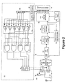
- FIG. 2 illustrates the system in more detail.
- the two antennas, A1 and A2 are arranged so as to produce substantially independent fading signals.
- the signals are split via splitters 40 and 42 and sent to electronically controlled switches 22 and 24.
- a control unit 44 selects each of the four possible states of switches 22 and 24 sequentially during an initial phase of operation, typically during a symbol guard interval.
- the output signal from switch 22 is filtered by a high-pass filter 26, which outputs only the upper half of its input signal bandwidth, while switch 24 is connected to a low-pass filter 28 which outputs only the lower half of its input signal bandwidth.
- the two filter outputs are summed by combiner 30 and the result forms the input to a conventional receiver circuit 8.
- the receiver circuit At its output, the receiver circuit produces individual carriers of the OFDM signal, which are normally demodulated by a demodulator 46.
- the carrier outputs are sent to a quality estimator 48 to estimate the quality of the resulting signal, typically using soft decision information or otherwise.
- a quality estimator 48 to estimate the quality of the resulting signal, typically using soft decision information or otherwise.
- the distances of the carrier outputs from the correct positions for the carrier constellation can be measured. It is not necessary to use all the carriers for quality estimation, although the carriers which are used should be spread throughout the frequency spectrum of the signal. It is possible to base the quality estimation on pilot carriers, by comparing their actual values with the known values they should adopt in a clean, noise-free system. Alternatively, spectrum estimation based on a limited number of samples could be used.
- the quality estimates for the four possible switch states are stored in a memory unit 50.
- a bank 52 of six comparators forms pairwise comparisons of all four quality estimates.
- the comparators are connected to a bank of four logical AND gates and associated NOT operations 54 which selects the largest of the four quality estimates.
- the result selects one of the four switch states within the control unit 44 and sets the switch states to correspond to the highest quality combination of branches. If the quality estimations can be achieved sufficiently quickly, which will depend on the process used, the switch state is preferably set during the current symbol, and more preferably before the beginning of the useful part of the symbol. The state is held for as long as appropriate (typically a symbol duration) before the whole process is repeated.
- the switch state could instead be set for the useful part of the next symbol (after first altering the state during the next guard interval for obtaining further quality estimates). It is not necessary to repeat the process regularly. Instead the process could be triggered by a detected deterioration in quality.
- the receiver circuit 8 shown in Figure 2 includes an RF tuner 82, which receives the signals from the antennas via the switches 22 and 24 and filters 26 and 28.
- the output of the tuner 82 is delivered to a down converter and IF amplifier 84, which supplies its output to an IF-to-baseband converter 86.
- the baseband signals from the converter 86 are sent to an FFT and channel estimation block 88, which generates the OFDM carrier signals for the receiver circuit output.
- the baseband signals are also delivered to a symbol synchronisation circuit 90, for synchronising the operation of the FFT and channel estimation block 88, and to a sample clock and frequency synchronisation circuit 92 which synchronises the operations of the down converter and IF amplifier 84 and the IF-to-baseband converter 86.
- FIG. 3 Another development of the basic approach is shown in Figure 3. This embodiment is largely similar to that of Figure 1, and like integers have like reference numerals.
- the antenna branches have been combined in a weighted combiner 60, with a fixed weighting to form another branch.
- This may be regarded as a fixed beam-steering network, which will have less fading in some parts of the band than either of the antennas alone. Again this can be extended to multiple combining networks and multiple sub-band filters. In the limit of having enough combining networks and sub-band filters, this approach will be capable of the same performance as maximal ratio diversity combining performed on every carrier. This approach will thus only produce a small extra performance gain over the previous case.
- the receiver circuit which is used to generate the main receiver output is also used for obtaining the measurements for the quality estimates, but this is not essential.
- the diversity system proposed is applicable to any wideband radio system, using any number of antennas. It is particularly relevant to applications at user terminals where power consumption, size and cost are particularly critical, whereas base stations will usually implement diversity combiners which use one receiver circuit per branch.
Abstract
Description
- This invention relates to antenna diversity receivers, particularly those suitable for use for wideband radio reception and more particularly for multi-carrier systems.
- Antenna diversity receivers use multiple antennas to overcome signal quality degradation caused by multipath fading. If the antennas are arranged such that their outputs fade independently, then the signals from the antennas can be combined to produce a signal with higher quality since it is unlikely that both antennas (branches) will simultaneously be in a deep fade. This allows the receiver to be used in areas with lower signal strengths or to provide higher signal quality and reliability within the normal system coverage area.
- A common form of diversity combiner is a switch combiner, in which only one complete receiver is needed. The receiver is switched between the antennas and makes a judgement as to which antenna provides the strongest signal. Numerous schemes for doing this exist, but it is believed that none of them address suitable strategies for wideband channels. In all cases, switch combining performs less well than selection combining, in which two receivers are available so that the performance of both antennas can be simultaneously monitored, but a switch is used to select the signal from only one of them at a time. Maximal ratio combining (MRC) involves using, simultaneously, a plurality of receivers each operating on a signal from a respective antenna, and using signal processing to combine the outputs of the receivers. This gives better performance than either switch combining or selection combining, but is somewhat more expensive.
- In a wideband fading channel, the bandwidth of the transmitted signal is wider than the coherence bandwidth of the channel (see S.R. Saunders, "Antennas and Propagation for Wireless Communication Systems", John Wiley & Sons, ISBN 0471986097, July 1999, for precise definitions). This implies that different parts of the received signal bandwidth will be faded to different extents, so the choice of the best antenna is not clear. A switch combiner could make a decision based on the total power available over the whole signal bandwidth, by performing a vector sum of the respective channel outputs of the receiver filter. However this yields only minor diversity gain when the delay spread is large, i.e. when there are significant delayed versions of the signal arriving at the receiver due to multipath echoes The results when selection combining is used instead of switch combining are not significantly better.
- Choosing a single antenna, based on whichever criteria, and using this for the reception of the whole ISDB-T bandwidth can lead to significant degradation in performance. Mostly, this will be due to the fact that somewhere within the signal bandwidth there will be a deep null, so although at some carriers within the bandwidth there may be excellent diversity gain, there is none achieved at other carriers, with the resultant diversity gain essentially an average across the bandwidth.
- Given that delay spread has been shown to produce this significant performance degradation, it would be attractive to have a combining technique which avoids this problem, but without the expense of MRC systems, and preferably using only one receiver.
- Accordingly, it would be desirable to provide a switch diversity combiner which preserves the low cost of having a single receiver, but has improved performance in high delay-spread environments than available from any conventional single receiver combiner.
- Aspects of the present invention are set out in the accompanying claims.
- According to a further aspect of the invention, a diversity switch combiner for use in systems for receiving wideband signals is arranged to split the received signal into separate channels each carrying a respective frequency band. Respective switch means are provided for each channel in order to switch the input of each channel between different antennas. A switch control determines the switch settings in accordance with the result of a comparison operation in which the signal qualities for different settings are compared.
- The invention is particularly applicable to multi-carrier signals which are transmitted in the form of symbols comprising a guard period followed by a useful part of the symbol, the guard period corresponding to the end of the useful part. In this case, the quality estimation is preferably performed during a guard period, so that the antenna switching can be carried out without causing a significant deterioration of performance.
- According to a still further aspect of the invention, a diversity switch combiner forms a path between the antennas and the receiver output, which path includes at least two channels each for carrying a respective frequency band of the received signal. Each channel has an independently operable switch means for selecting which of the signals from the antennas are fed through the channel. The receiver output is based on the combined output of the channels. Accordingly, enhanced performance throughout the frequency range of the received radio signal can be achieved.
- The combiner is preferably located between the antennas and the receiver, and thus conveys RF signals to the receiver. Alternatively, the combiner could be located within the receiver, e.g. in the IF section, although in this case separate versions of the circuits prior to the combiner would have to be provided for the respective channels.
- The approach can be extended to as many channels as desired, until the resilience against delay spread is sufficient to account for the prevailing channel conditions. Ultimately the performance can be made to approach arbitrarily closely to the performance of switching performed on every carrier independently. At this level diversity gains may be around 9 or 10dB.
- Arrangements embodying the invention will now be described by way of example with reference to the accompanying drawings, in which:
- Figure 1 schematically illustrates a receiver system according to a first embodiment of the invention;
- Figure 2 is a more detailed block diagram of the receiver system of Figure 1; and
- Figure 3 schematically illustrates a receiver system of a second embodiment of the invention.
-
- In Figure 1, a basic embodiment of the invention is shown. The
receiver system 2, which is intended for receiving OFDM (Orthogonal Frequency Division Multiplex) signals, includes anantenna section 4, aswitch combining section 6 and areceiver circuit 8 which includes means for converting the received signal to baseband. - In the
antenna section 2, two antennas, A1 and A2, are arranged so that their outputs fade independently. The outputs are coupled to aswitch block 20 of theswitch combining section 6. Theblock 20 incorporates twoswitches filters filters combiner 30, the output of which is delivered to thereceiver circuit 8. - The
switch combining section 6 also includesswitch logic 32 responsive to signals from thereceiver circuit 8 for choosing which of the antennas should be routed to each of the filters. This can be based on a comparison of the possible switch states examined during a guard period of the received signal. Thus a deep null in one antenna in one half of the segment can be avoided if it is not present in the other antenna. The system is then resilient to almost twice the delay spread as conventional full-band switching. - Figure 2 illustrates the system in more detail. The two antennas, A1 and A2, are arranged so as to produce substantially independent fading signals. The signals are split via
splitters switches control unit 44 selects each of the four possible states ofswitches switch 22 is filtered by a high-pass filter 26, which outputs only the upper half of its input signal bandwidth, whileswitch 24 is connected to a low-pass filter 28 which outputs only the lower half of its input signal bandwidth. The two filter outputs are summed by combiner 30 and the result forms the input to aconventional receiver circuit 8. At its output, the receiver circuit produces individual carriers of the OFDM signal, which are normally demodulated by ademodulator 46. - The carrier outputs are sent to a
quality estimator 48 to estimate the quality of the resulting signal, typically using soft decision information or otherwise. There are various known ways of estimating signal quality. For example, the distances of the carrier outputs from the correct positions for the carrier constellation can be measured. It is not necessary to use all the carriers for quality estimation, although the carriers which are used should be spread throughout the frequency spectrum of the signal. It is possible to base the quality estimation on pilot carriers, by comparing their actual values with the known values they should adopt in a clean, noise-free system. Alternatively, spectrum estimation based on a limited number of samples could be used. - The quality estimates for the four possible switch states are stored in a
memory unit 50. Abank 52 of six comparators forms pairwise comparisons of all four quality estimates. The comparators are connected to a bank of four logical AND gates and associated NOToperations 54 which selects the largest of the four quality estimates. The result selects one of the four switch states within thecontrol unit 44 and sets the switch states to correspond to the highest quality combination of branches. If the quality estimations can be achieved sufficiently quickly, which will depend on the process used, the switch state is preferably set during the current symbol, and more preferably before the beginning of the useful part of the symbol. The state is held for as long as appropriate (typically a symbol duration) before the whole process is repeated. If the quality estimation takes too long to be of value for the current symbol, the switch state could instead be set for the useful part of the next symbol (after first altering the state during the next guard interval for obtaining further quality estimates). It is not necessary to repeat the process regularly. Instead the process could be triggered by a detected deterioration in quality. - The
receiver circuit 8 shown in Figure 2 includes anRF tuner 82, which receives the signals from the antennas via theswitches filters tuner 82 is delivered to a down converter and IFamplifier 84, which supplies its output to an IF-to-baseband converter 86. The baseband signals from theconverter 86 are sent to an FFT andchannel estimation block 88, which generates the OFDM carrier signals for the receiver circuit output. The baseband signals are also delivered to asymbol synchronisation circuit 90, for synchronising the operation of the FFT andchannel estimation block 88, and to a sample clock andfrequency synchronisation circuit 92 which synchronises the operations of the down converter and IFamplifier 84 and the IF-to-baseband converter 86. - This is merely one example of a number of different types of receiver circuits which could be employed in the system of Figure 2. In alternative arrangements, the
switches filters receiver circuit 8, for example between the down converter and IFamplifier 84 and the IF-to-baseband converter 86, with suitable modifications to the filter characteristics and duplication of the circuits preceding theconverter 86. - Another development of the basic approach is shown in Figure 3. This embodiment is largely similar to that of Figure 1, and like integers have like reference numerals. In the embodiment of Figure 3, however, the antenna branches have been combined in a
weighted combiner 60, with a fixed weighting to form another branch. This may be regarded as a fixed beam-steering network, which will have less fading in some parts of the band than either of the antennas alone. Again this can be extended to multiple combining networks and multiple sub-band filters. In the limit of having enough combining networks and sub-band filters, this approach will be capable of the same performance as maximal ratio diversity combining performed on every carrier. This approach will thus only produce a small extra performance gain over the previous case. - In all cases two basic front ends (each comprising a splitter, a switch and a filter) are required in order to have simultaneous access to signals from both antennas. This may not necessarily be more economical than performing MRC at the receiver IF, but the choice will depend on the relative costs of the various RF components.
- It is envisaged that the receiver circuit which is used to generate the main receiver output is also used for obtaining the measurements for the quality estimates, but this is not essential.
- The diversity system proposed is applicable to any wideband radio system, using any number of antennas. It is particularly relevant to applications at user terminals where power consumption, size and cost are particularly critical, whereas base stations will usually implement diversity combiners which use one receiver circuit per branch.
- Particular systems which are applicable are:
- ISDB-T
- DAB
- DVB
- UMTS
- cdma2000
Claims (9)
- A diversity switch combiner for a receiver system comprising a plurality of antennas and a receiver circuit for converting signals from the antennas into baseband signals provided at a baseband output, the combiner comprising at least two signal channels between the antennas and the baseband output, each channel being arranged to carry a respective frequency band of the received signal, switch means for selectively coupling the antennas to each signal channel and switch control means which is operable to determine the quality of the signals carried by the signal channels for different settings of the respective switch means, and to control the setting of the switch means in dependence upon the quality determination.
- A combiner as claimed in claim 1, wherein each signal channel includes a filter for restricting the frequency band transmitted by the channel.
- A combiner as claimed in claim 1 or claim 2, for use in a receiver system for receiving signals in the form of successive symbols including guard periods, wherein the switch control means is operable to alter the switch settings during the guard period in order to determine the quality of the transmitted signals in each respective frequency band, and is thereafter operable to control the setting in accordance with the determined quality.
- A combiner as claimed in claim 3, wherein the switch control means is operable to determine the signal qualities during each guard period so as to control the switch setting for the current symbol.
- A combiner as claimed in any preceding claim, wherein each signal channel is arranged to carry RF signals.
- A combiner as claimed in any one of claims 1 to 4, wherein each signal channel is arranged to carry IF signals.
- A receiver system comprising a plurality of antennas, a receiver circuit for converting signals received from the antennas into baseband signals, and a diversity switch combiner as claimed in any preceding claim.
- A receiver system as claimed in claim 7, including a combining means for combining signals from a plurality of antennas, the switch means being arranged selectively to couple to each respective signal channel the outputs of the antennas and the combining means.
- A method of operating a wideband receiver having at least two antennas, the method comprising :separating the received signal into respective frequency bands;for each frequency band, determining the quality of the signals received from the respective antennas;for each frequency band, independently selecting the antenna which provides the highest quality signal; andcombining the separated signals as received by each selected antenna and demodulating the combined signal.
Priority Applications (3)
| Application Number | Priority Date | Filing Date | Title |
|---|---|---|---|
| EP03257283A EP1533916A1 (en) | 2003-11-18 | 2003-11-18 | Diversity switch combiner |
| US10/984,894 US7636561B2 (en) | 2003-11-18 | 2004-11-10 | Diversity switch combiner |
| JP2004334683A JP2005192200A (en) | 2003-11-18 | 2004-11-18 | Diversity switch combiner, receiver system equipped with the diversity switch combiner, and method for operating wideband receiver |
Applications Claiming Priority (1)
| Application Number | Priority Date | Filing Date | Title |
|---|---|---|---|
| EP03257283A EP1533916A1 (en) | 2003-11-18 | 2003-11-18 | Diversity switch combiner |
Publications (1)
| Publication Number | Publication Date |
|---|---|
| EP1533916A1 true EP1533916A1 (en) | 2005-05-25 |
Family
ID=34429535
Family Applications (1)
| Application Number | Title | Priority Date | Filing Date |
|---|---|---|---|
| EP03257283A Withdrawn EP1533916A1 (en) | 2003-11-18 | 2003-11-18 | Diversity switch combiner |
Country Status (3)
| Country | Link |
|---|---|
| US (1) | US7636561B2 (en) |
| EP (1) | EP1533916A1 (en) |
| JP (1) | JP2005192200A (en) |
Cited By (1)
| Publication number | Priority date | Publication date | Assignee | Title |
|---|---|---|---|---|
| WO2008028942A1 (en) * | 2006-09-07 | 2008-03-13 | Telefonaktiebolaget Lm Ericsson (Publ) | Method of receiving wideband signal with multiple antennas and corresponding receiver |
Families Citing this family (15)
| Publication number | Priority date | Publication date | Assignee | Title |
|---|---|---|---|---|
| EP1533917A1 (en) * | 2003-11-18 | 2005-05-25 | Mitsubishi Electric Information Technology Centre Europe B.V. | Antenna diversity switch for a receiver system and method using this switch |
| EP1533916A1 (en) | 2003-11-18 | 2005-05-25 | Mitsubishi Electric Information Technology Centre Europe B.V. | Diversity switch combiner |
| US6990324B2 (en) * | 2004-04-15 | 2006-01-24 | Flarion Technologies, Inc. | Methods and apparatus for selecting between multiple carriers using a single receiver chain tuned to a single carrier |
| JP4425711B2 (en) * | 2004-05-31 | 2010-03-03 | 京セラ株式会社 | Antenna control method and radio transmission / reception apparatus |
| CN101048959A (en) * | 2004-09-23 | 2007-10-03 | 加利福尼亚大学董事会 | Multiple sub-carrier selection diversity architecture and method for wireless OFDM |
| US20070026898A1 (en) * | 2005-07-26 | 2007-02-01 | Lear Corporation | System and method for use in wireless communication employing multiple antennas |
| US20070024510A1 (en) * | 2005-07-26 | 2007-02-01 | Lear Corporation | System and method for use in wireless communication employing multiple antennas |
| EP2118966A4 (en) * | 2005-12-12 | 2014-06-04 | Flextronics Ap Llc | Wideband antenna system |
| US7667659B2 (en) * | 2006-01-25 | 2010-02-23 | Sky Cross, Inc. | Antenna system for receiving digital video broadcast signals |
| KR100961887B1 (en) * | 2006-06-05 | 2010-06-09 | 삼성전자주식회사 | Apparatus and method for channel sounding of terminal in wireless communication system |
| TW200906186A (en) * | 2007-07-24 | 2009-02-01 | Asustek Comp Inc | Multi-antenna digital television box |
| US10211704B2 (en) * | 2015-08-29 | 2019-02-19 | Abb Schweiz Ag | Fluid-cooled stator assemblies having multilayer and multifunctional tubing |
| US10097231B1 (en) * | 2017-07-03 | 2018-10-09 | Mediatek Inc. | Radio transceiver and RF signal processing device |
| JP7042912B2 (en) * | 2018-07-13 | 2022-03-28 | 三菱電機株式会社 | Broadcast receiving device and broadcasting receiving method |
| EP3660981B8 (en) * | 2018-11-29 | 2021-06-02 | Rohde & Schwarz GmbH & Co. KG | Spatial and bandwidth multiplexing device and method |
Citations (5)
| Publication number | Priority date | Publication date | Assignee | Title |
|---|---|---|---|---|
| US6009307A (en) * | 1997-05-13 | 1999-12-28 | Qualcomm Incorporated | Multiple antenna detecting and selecting |
| US20030002471A1 (en) * | 2001-03-06 | 2003-01-02 | Crawford James A. | Method for estimating carrier-to-noise-plus-interference ratio (CNIR) for OFDM waveforms and the use thereof for diversity antenna branch selection |
| EP1294154A2 (en) * | 2001-09-14 | 2003-03-19 | Fujitsu Limited | OFDM receiving method and apparatus |
| EP1296466A2 (en) * | 2001-09-25 | 2003-03-26 | AT&T Corp. | Multi-antenna/Multi-receiver array diversity system |
| WO2003073682A1 (en) * | 2002-01-28 | 2003-09-04 | Kabushiki Kaisha Toshiba | Ofdm signal selection systems |
Family Cites Families (28)
| Publication number | Priority date | Publication date | Assignee | Title |
|---|---|---|---|---|
| DE69327837T2 (en) * | 1992-12-01 | 2000-10-12 | Koninkl Philips Electronics Nv | Subband diversity transmission system |
| GB2308530B (en) * | 1995-12-21 | 2000-03-22 | Nokia Mobile Phones Ltd | Antenna selection control circuitry |
| JP3377361B2 (en) * | 1996-04-12 | 2003-02-17 | 日本放送協会 | Diversity receiver |
| JPH10215238A (en) * | 1997-01-28 | 1998-08-11 | Ricoh Co Ltd | Direct spread spectrum diversity receiver |
| JP3303819B2 (en) * | 1999-02-02 | 2002-07-22 | 日本電気株式会社 | Diversity receiving method and diversity receiver |
| US6263195B1 (en) * | 1999-02-12 | 2001-07-17 | Trw Inc. | Wideband parallel processing digital tuner |
| US6314127B1 (en) * | 1999-02-23 | 2001-11-06 | Lucent Technologies Inc. | System and method for enhancing signal reception |
| DE19916855A1 (en) * | 1999-04-14 | 2000-10-26 | Heinz Lindenmeier | Radio telephone system with group antenna for vehicles |
| JP2001308762A (en) * | 2000-04-21 | 2001-11-02 | Pioneer Electronic Corp | Receiver for digital broadcasting |
| JP3660209B2 (en) * | 2000-05-25 | 2005-06-15 | 松下電器産業株式会社 | Wireless communication device |
| GB0016411D0 (en) * | 2000-07-05 | 2000-08-23 | Koninkl Philips Electronics Nv | Antenna diversity receiver |
| US7054375B2 (en) * | 2000-12-22 | 2006-05-30 | Nokia Corporation | Method and apparatus for error reduction in an orthogonal modulation system |
| US7065146B1 (en) * | 2002-02-15 | 2006-06-20 | Marvell International Ltd. | Method and apparatus for equalization and decoding in a wireless communications system including plural receiver antennae |
| GB0110907D0 (en) * | 2001-05-03 | 2001-06-27 | British Broadcasting Corp | Improvements in decoders for many carrier signals, in particular in DVB-T recievers |
| US7280504B2 (en) * | 2001-09-28 | 2007-10-09 | Kabushiki Kaisha Toshiba | OFDM transmitting and receiving apparatus |
| FR2833435B1 (en) | 2001-12-06 | 2004-02-27 | Thomson Licensing Sa | RECEPTION PATH SELECTION METHOD AND RECEPTION DEVICE INCLUDING SEVERAL RECEPTION PATHS |
| KR100446507B1 (en) * | 2001-12-27 | 2004-09-04 | 삼성전자주식회사 | Diversity apparatus and method of mobile telecommunication terminal |
| JP2003283411A (en) * | 2002-03-22 | 2003-10-03 | Sanyo Electric Co Ltd | Radio equipment, transmission reception directivity control method, and transmission reception directivity control program |
| US7072628B2 (en) * | 2002-04-05 | 2006-07-04 | Qualcomm, Incorporated | Method and apparatus for determining receive diversity in mobile station |
| US6728517B2 (en) * | 2002-04-22 | 2004-04-27 | Cognio, Inc. | Multiple-input multiple-output radio transceiver |
| US6907272B2 (en) * | 2002-07-30 | 2005-06-14 | UNIVERSITé LAVAL | Array receiver with subarray selection |
| US20040198420A1 (en) * | 2002-08-21 | 2004-10-07 | Ziming He | RF front-end of dual-mode wireless transciver |
| JP3672196B2 (en) * | 2002-10-07 | 2005-07-13 | 松下電器産業株式会社 | Antenna device |
| US7929985B2 (en) * | 2003-05-01 | 2011-04-19 | Telefonaktiebolaget Lm Ericsson (Publ) | Multiple antenna receiver |
| US7595768B2 (en) * | 2003-06-27 | 2009-09-29 | Intel Corporation | Switching schemes for multiple antennas |
| US6922549B2 (en) * | 2003-10-31 | 2005-07-26 | Cisco Technology, Inc. | Error vector magnitude selection diversity metric for OFDM |
| EP1533917A1 (en) * | 2003-11-18 | 2005-05-25 | Mitsubishi Electric Information Technology Centre Europe B.V. | Antenna diversity switch for a receiver system and method using this switch |
| EP1533916A1 (en) | 2003-11-18 | 2005-05-25 | Mitsubishi Electric Information Technology Centre Europe B.V. | Diversity switch combiner |
-
2003
- 2003-11-18 EP EP03257283A patent/EP1533916A1/en not_active Withdrawn
-
2004
- 2004-11-10 US US10/984,894 patent/US7636561B2/en active Active
- 2004-11-18 JP JP2004334683A patent/JP2005192200A/en active Pending
Patent Citations (5)
| Publication number | Priority date | Publication date | Assignee | Title |
|---|---|---|---|---|
| US6009307A (en) * | 1997-05-13 | 1999-12-28 | Qualcomm Incorporated | Multiple antenna detecting and selecting |
| US20030002471A1 (en) * | 2001-03-06 | 2003-01-02 | Crawford James A. | Method for estimating carrier-to-noise-plus-interference ratio (CNIR) for OFDM waveforms and the use thereof for diversity antenna branch selection |
| EP1294154A2 (en) * | 2001-09-14 | 2003-03-19 | Fujitsu Limited | OFDM receiving method and apparatus |
| EP1296466A2 (en) * | 2001-09-25 | 2003-03-26 | AT&T Corp. | Multi-antenna/Multi-receiver array diversity system |
| WO2003073682A1 (en) * | 2002-01-28 | 2003-09-04 | Kabushiki Kaisha Toshiba | Ofdm signal selection systems |
Cited By (1)
| Publication number | Priority date | Publication date | Assignee | Title |
|---|---|---|---|---|
| WO2008028942A1 (en) * | 2006-09-07 | 2008-03-13 | Telefonaktiebolaget Lm Ericsson (Publ) | Method of receiving wideband signal with multiple antennas and corresponding receiver |
Also Published As
| Publication number | Publication date |
|---|---|
| JP2005192200A (en) | 2005-07-14 |
| US20060009176A1 (en) | 2006-01-12 |
| US7636561B2 (en) | 2009-12-22 |
Similar Documents
| Publication | Publication Date | Title |
|---|---|---|
| US7636561B2 (en) | Diversity switch combiner | |
| US7636593B2 (en) | Receiver | |
| EP1671432B1 (en) | System and method for antenna selection | |
| EP0983644B1 (en) | Selective diversity combining | |
| EP1906552B1 (en) | Space and time diversity gain | |
| US6151487A (en) | Demodulation structure for fast fading cellular channels | |
| US5528581A (en) | Diversity transmission system for sub-band diversity reception | |
| US20050078649A1 (en) | Apparatus and method of multiple antenna receiver combining of high data rate wideband packetized wireless communication signals | |
| US20040008614A1 (en) | Signal selection systems | |
| US20050113048A1 (en) | Receiver, receiving method, reception controlling program, and recording medium | |
| EP1685662A1 (en) | System and method for channel-adaptive antenna selection | |
| JP2000278243A (en) | Diversity receiver | |
| WO2001013463A1 (en) | Method of and apparatus for beam reduction and combining in a radio communications system | |
| JP2000224139A (en) | Diversity receiver | |
| WO2009056505A1 (en) | Wireless receiver with receive diversity | |
| US7643813B2 (en) | Diversity switch combiner | |
| JP3639521B2 (en) | Diversity receiver and orthogonal frequency division multiplex signal receiving method | |
| JP4095602B2 (en) | Receiver | |
| JP2003309501A (en) | Radio receiver and radio receiving method | |
| JP2001267986A (en) | Digital radio receiver | |
| JP4011384B2 (en) | Diversity receiver | |
| JP3679325B2 (en) | Diversity receiver and orthogonal frequency division multiplex signal receiving method | |
| JP2002368661A (en) | Selection synthesis diversity receiver | |
| JP3606450B2 (en) | Diversity receiver and orthogonal frequency division multiplexing signal receiving method | |
| JP2008148312A (en) | Receiver module and method for receiving signal using diversity switched combining |
Legal Events
| Date | Code | Title | Description |
|---|---|---|---|
| PUAI | Public reference made under article 153(3) epc to a published international application that has entered the european phase |
Free format text: ORIGINAL CODE: 0009012 |
|
| AK | Designated contracting states |
Kind code of ref document: A1 Designated state(s): AT BE BG CH CY CZ DE DK EE ES FI FR GB GR HU IE IT LI LU MC NL PT RO SE SI SK TR |
|
| AX | Request for extension of the european patent |
Extension state: AL LT LV MK |
|
| 17P | Request for examination filed |
Effective date: 20051122 |
|
| AKX | Designation fees paid |
Designated state(s): DE FR GB |
|
| RAP1 | Party data changed (applicant data changed or rights of an application transferred) |
Owner name: MITSUBISHI DENKI KABUSHIKI KAISHA Owner name: MITSUBISHI ELECTRIC INFORMATION TECHNOLOGY CENTRE |
|
| RAP1 | Party data changed (applicant data changed or rights of an application transferred) |
Owner name: MITSUBISHI DENKI KABUSHIKI KAISHA Owner name: MITSUBISHI ELECTRIC INFORMATION TECHNOLOGY CENTRE |
|
| 17Q | First examination report despatched |
Effective date: 20090219 |
|
| GRAP | Despatch of communication of intention to grant a patent |
Free format text: ORIGINAL CODE: EPIDOSNIGR1 |
|
| STAA | Information on the status of an ep patent application or granted ep patent |
Free format text: STATUS: THE APPLICATION IS DEEMED TO BE WITHDRAWN |
|
| 18D | Application deemed to be withdrawn |
Effective date: 20121113 |