EP1533986A2 - Communication device that provides enhanced services - Google Patents
Communication device that provides enhanced services Download PDFInfo
- Publication number
- EP1533986A2 EP1533986A2 EP04256861A EP04256861A EP1533986A2 EP 1533986 A2 EP1533986 A2 EP 1533986A2 EP 04256861 A EP04256861 A EP 04256861A EP 04256861 A EP04256861 A EP 04256861A EP 1533986 A2 EP1533986 A2 EP 1533986A2
- Authority
- EP
- European Patent Office
- Prior art keywords
- digital
- signals
- voice signals
- user
- pots
- Prior art date
- Legal status (The legal status is an assumption and is not a legal conclusion. Google has not performed a legal analysis and makes no representation as to the accuracy of the status listed.)
- Ceased
Links
- 238000004891 communication Methods 0.000 title claims abstract description 100
- 238000006243 chemical reaction Methods 0.000 claims abstract description 17
- 238000001514 detection method Methods 0.000 claims description 16
- 238000000034 method Methods 0.000 claims description 10
- 230000005540 biological transmission Effects 0.000 description 7
- RYGMFSIKBFXOCR-UHFFFAOYSA-N Copper Chemical compound [Cu] RYGMFSIKBFXOCR-UHFFFAOYSA-N 0.000 description 5
- 208000032041 Hearing impaired Diseases 0.000 description 1
- 230000006870 function Effects 0.000 description 1
- 230000010354 integration Effects 0.000 description 1
- 230000002093 peripheral effect Effects 0.000 description 1
- 230000032258 transport Effects 0.000 description 1
Images


Classifications
-
- H—ELECTRICITY
- H04—ELECTRIC COMMUNICATION TECHNIQUE
- H04M—TELEPHONIC COMMUNICATION
- H04M11/00—Telephonic communication systems specially adapted for combination with other electrical systems
- H04M11/06—Simultaneous speech and data transmission, e.g. telegraphic transmission over the same conductors
- H04M11/062—Simultaneous speech and data transmission, e.g. telegraphic transmission over the same conductors using different frequency bands for speech and other data
-
- H—ELECTRICITY
- H04—ELECTRIC COMMUNICATION TECHNIQUE
- H04L—TRANSMISSION OF DIGITAL INFORMATION, e.g. TELEGRAPHIC COMMUNICATION
- H04L12/00—Data switching networks
- H04L12/28—Data switching networks characterised by path configuration, e.g. LAN [Local Area Networks] or WAN [Wide Area Networks]
-
- H—ELECTRICITY
- H04—ELECTRIC COMMUNICATION TECHNIQUE
- H04M—TELEPHONIC COMMUNICATION
- H04M1/00—Substation equipment, e.g. for use by subscribers
- H04M1/247—Telephone sets including user guidance or feature selection means facilitating their use
- H04M1/2478—Telephone terminals specially adapted for non-voice services, e.g. email, internet access
-
- H—ELECTRICITY
- H04—ELECTRIC COMMUNICATION TECHNIQUE
- H04M—TELEPHONIC COMMUNICATION
- H04M1/00—Substation equipment, e.g. for use by subscribers
- H04M1/253—Telephone sets using digital voice transmission
-
- H—ELECTRICITY
- H04—ELECTRIC COMMUNICATION TECHNIQUE
- H04M—TELEPHONIC COMMUNICATION
- H04M1/00—Substation equipment, e.g. for use by subscribers
- H04M1/253—Telephone sets using digital voice transmission
- H04M1/2535—Telephone sets using digital voice transmission adapted for voice communication over an Internet Protocol [IP] network
-
- H—ELECTRICITY
- H04—ELECTRIC COMMUNICATION TECHNIQUE
- H04M—TELEPHONIC COMMUNICATION
- H04M2201/00—Electronic components, circuits, software, systems or apparatus used in telephone systems
- H04M2201/60—Medium conversion
-
- H—ELECTRICITY
- H04—ELECTRIC COMMUNICATION TECHNIQUE
- H04M—TELEPHONIC COMMUNICATION
- H04M2207/00—Type of exchange or network, i.e. telephonic medium, in which the telephonic communication takes place
- H04M2207/20—Type of exchange or network, i.e. telephonic medium, in which the telephonic communication takes place hybrid systems
- H04M2207/203—Type of exchange or network, i.e. telephonic medium, in which the telephonic communication takes place hybrid systems composed of PSTN and data network, e.g. the Internet
-
- H—ELECTRICITY
- H04—ELECTRIC COMMUNICATION TECHNIQUE
- H04M—TELEPHONIC COMMUNICATION
- H04M7/00—Arrangements for interconnection between switching centres
- H04M7/0012—Details of application programming interfaces [API] for telephone networks; Arrangements which combine a telephonic communication equipment and a computer, i.e. computer telephony integration [CPI] arrangements
Landscapes
- Engineering & Computer Science (AREA)
- Signal Processing (AREA)
- Computer Networks & Wireless Communication (AREA)
- Computer Vision & Pattern Recognition (AREA)
- Human Computer Interaction (AREA)
- Telephonic Communication Services (AREA)
- Telephone Function (AREA)
Abstract
Description
- The invention is related to the field of communication systems, and in particular, to communication devices and methods of operating communication devices that provide enhanced services to users.
- Almost every house, apartment, condo, etc. is wired for phone service, commonly called POTS service. On a daily basis, people use the POTS service to place calls for business and personal use. The wiring for POTS service is typically a twisted-pair copper wire that connects the home to a central office of the local telephone company. The connection between the central office and the home over the twisted-pair wire is sometimes referred to as the "last mile". For POTS service, a phone takes acoustic signals and converts them into analog signals that are the electrical equivalent of the acoustic signals in terms of volume and pitch. The phone then transmits analog signals to the central office.
- The central office applies a low voltage to the twisted-pair wire using a power supply or battery. The voltage on the wire provides power to phones in the home. Because the central office provides power to the twisted-pair wire, phones in the home work even if the commercial electric power goes out in the home.
- Recently, Internet access and email have become a daily routine. Many people access the Internet and their email accounts from a home computer using POTS service. Because the central office expects an analog signal, the home computer uses a modem to modulate digital data from the computer into analog signals. The modem then transmits the analog signals over the twisted-pair wire to the central office.
- The analog transmission between the home computer and the central office only uses a portion of the twisted-pair wire potential bandwidth for transmission, which limits the bandwidth available to the home computer. Also, if the central office receives digital data destined for the home computer, the central office has to convert the digital data to analog signals and transmit the analog signals over the twisted-pair wire. The modem of the home computer then converts the analog signals back to the digital data. The conversion back and forth between digital and analog may limit the available bandwidth to about 56 Kbps. Consequently, the POTS service may not provide a desired bandwidth for accessing the Internet, sending emails, or other applications.
- To receive higher bandwidths over the existing twisted-pair wire, communication providers have implemented services such as Digital Subscriber Line (DSL) service. DSL service provides voice service and data service simultaneously over the twisted-pair wire. Depending on the distance and twisted-pair circuit quality, a user subscribing to the DSL service can advantageously receive a bandwidth around 1.544 Gbits/s for accessing the Internet while still retaining traditional POTS service.
- For DSL service, a DSL modem transmits digital signals at a high frequency over the twisted-pair wire simultaneously as analog signals travel over the twisted-pair wire at a low frequency. The analog signals comprise traditional POTS service generally used for voice calls. The digital signals are generally used for data services, such as accessing the Internet or sending email, but may also be used for voice calls, such as Voice over Internet Protocol (VoIP) calls. For the data services, a computer connects to an Internet Service Provider (ISP) through the DSL modem. Once connected to the ISP, the computer may receive digital signals directly from the ISP. The computer can receive the digital signals at a higher bandwidth than if the central office had to convert the digital signals to an analog signal.
- Unlike the POTS service, the central office does not provide power to the DSL modem or the computer. The computer needs an independent power supply to operate. If the power is interrupted to the computer, the computer is not able to operate.
- Another way to receive higher bandwidths is to subscribe to cable service. Cable service utilizes a coaxial cable for the cable service for high bandwidth data services. The user maintains POTS service separately over the twisted-pair wire. With cable service, the user can simultaneously use the POTS service for voice calls and use the cable service for accessing the Internet or sending email.
- Although current computers can receive DSL service to make calls and surf the Internet, the features provided to the user for communications is limited. The voice features offered to the user are limited to the features normally provided by the POTS service (and the phone company). The features include voice mail, call waiting, and caller ID. The data services provided by DSL service are not currently used to add features to the POTS service. The POTS service (voice service) is typically used for phones and the DSL service (data service) is typically used for Internet and email. The POTS service is not used to enhance the data service and the data service is not used to enhance POTS service. Therefore, the features available to a user are limited, and a user may desire other features that are not currently available.
- Also, computers set up for DSL service require power to operate. If the power is interrupted to the computer, then the computer can no longer communicate voice or data. This may be unfortunate in the event of brown outs, power surges, terrorist acts, storms, etc.
- The invention solves the above problems and other problems with a communication device and a method of operating a communication device in exemplary embodiments described herein. One exemplary embodiment is a communication device that operates as follows to provide enhanced services to a user. For voice services, a POTS interface system in the communication device receives analog voice signals for a call from a POTS provider over a wireline. The POTS interface system converts the analog voice signals from analog format to digital format to generate digital voice signals, and forwards the digital voice signals to a processing system. Responsive to the digital voice signals, the processing system performs an application on the digital voice signals to provide one or more presentation formats of the digital voice signals of the call to a user. Some presentation formats of the digital voice signals may include: displaying text of the call, storing the text, printing the text, etc. The processing system forwards the digital voice signals to a conversion system to complete the call to the user. The conversion system converts the digital voice signals into analog voice signals, and forwards the analog voice signals to a voice interface system. The voice interface system transmits audible signals to the user representing the analog voice signals.
- For data services, a digital signal interface in the communication device receives digital data signals from a data service provider. The digital signal interface forwards the digital data signals to the processing system. Responsive to the digital data signals, the processing system performs an application on the digital data signals to provide additional data to the user. Some examples of providing additional data include: displaying a telephone directory, displaying text messages, displaying a web page, displaying more caller ID information, etc.
- The communication device advantageously provides enhanced communications to the user by providing more features to the user with a single communication device. There is currently no terminal device that integrates voice service and data services to provide enhanced communications as the communication device herein. With the communication device, a user may make a voice call over a POTS connection while surfing the Internet, using only one device.
- One way the communication device provides more features to the user is by digitizing the analog voice signals from the POTS provider. By digitizing the analog voice signals, the communication device may provide the call in any presentation format available for digital signals. For instance, communication device may generate text from the digital voice signals of the call and display the text to the user. The user can then read what was said in a conversation as the text of the conversation is displayed to the user. The user may also store part or all of the text of the conversation in a soft copy for future reference or print the text of the conversation in a hard copy.
- The communication device may also perform any function for the call that can be performed on digital signals. For instance, the communication device may format the digital voice signals for wireless transmission of the digital voice signals to remote wireless devices.
- In another exemplary embodiment, the communication device further includes a power supply system, a power detection system, and POTS circuitry. The power supply system provides power to the communication device. The power detection system detects an interrupt in the power provided by the power supply system. The POTS circuitry is coupled between the wireline and the POTS interface system, and the wireline and the voice interface system. The POTS circuitry receives analog voice signals from the wireline. The POTS circuitry forwards the analog voice signals to the POTS interface system responsive to the power detection system not detecting an interrupt in power to the communication device. If the POTS circuitry does detect an interrupt in power, then the POTS circuitry forwards the analog voice signals to the voice interface system.
- The communication device in this embodiment is more reliable because it can operate when the power is interrupted. If the power to the communication device is interrupted, the communication device advantageously reverts back to regular POTS service. The POTS circuitry is powered by the voltage put on the wireline by the central office and not by the power supply system. Therefore, the user may still make voice calls with the communication device when the power is interrupted.
- The invention may include other embodiments described below.
- The same reference number represents the same element on all drawings.
- FIG. 1 illustrates a customer premises in the prior art.
- FIG. 2 illustrates a communication device in an exemplary embodiment of the invention.
- FIG. 3 illustrates a communication device in an exemplary embodiment of the invention.
- FIG. 4 illustrates a customer premises coupled to a communication network in an exemplary embodiment of the invention.
- FIG. 5 illustrates the components of a terminal device in an exemplary embodiment of the invention.
- FIG. 6 illustrates the interfaces of a terminal device in an exemplary embodiment of the invention.
- FIG. 1 illustrates a
customer premises 100 in the prior art to help better understand the invention. Examples ofcustomer premises 100 include a house, an apartment, and a condo.Customer premises 100 includes aphone line 102, such as a twisted-pair copper wire installed in many homes. The other end ofphone line 102 connects to a central office (not shown) of a local phone company. Assume that a user incustomer premises 100 has subscribed to Digital Subscriber Line (DSL) service overphone line 102. The DSL service provides for the transfer of DSL signals overphone line 102. The central office may include a Digital Subscriber Line Access Multiplexer (DSLAM) for the DSL service.Customer premises 100 also includes aphone 110, aphone 130, and acomputer 140 coupled tophone line 102. -
Phone 110 connects tophone line 102 through aDSL filter 112.Phone 110 is a conventional POTS phone. -
Phone 130 connects tophone line 102 through aDSL splitter 120.Phone 130 is also a conventional POTS phone.Phone 130 includes ahandset 132, akeypad 134, andPOTS circuitry 136.Handset 132 includes aspeaker 137 and amicrophone 138.POTS circuitry 136 comprises conventional circuitry used in phones for POTS service. -
Computer 140 connects tophone line 102 throughDSL splitter 120 and aDSL modem 142.Computer 140 includes a Central Processing Unit (CPU) 143, adisplay 144, akeyboard 145, amouse 146, aspeaker 147, and amicrophone 148.Computer 140 also includes a power supply (not shown) coupled to apower source 150 to provide power tocomputer 140. - For DSL service,
phone line 102 transports DSL signals. The DSL signals include digital signals at a high frequency and analog signals at a low frequency. The analog signals comprise traditional POTS service generally used for voice calls. The digital signals are generally used for data services, such as accessing the Internet or sending email. - By connecting to
phone line 102,phone 110 receives POTS service.DSL filter 112 filters out frequencies other than the frequencies used for the POTS service.Phone 110 may have a humming noise ifDSL filter 112 is not installed. Whenphone 110 is connected tophone line 102, the user may make a call over the Public Switched Telephone Network (PSTN). With the POTS service,phone 110 receives a low voltage signal from the central office that powersphone 110.Phone 110 is able to operate even ifcustomer premises 100 loses power. -
DSL splitter 120 splits the DSL signals betweenphone 130 andcomputer 140.DSL splitter 120 splits the DSL signals into analog signals and digital signals.DSL splitter 120 forwards the analog signals used for the POTS service tophone 130. The user may make a call withphone 130 over the Public Switched Telephone Network (PSTN) using the POTS service. As withphone 110,phone 130 receives a low voltage signal from the central office that powersphone 130. -
DSL splitter 120 forwards the digital signals toDSL modem 142. The user may access data services, such as accessing the Internet or sending email, withcomputer 140. The DSL service may provide a desired bandwidth for accessing the Internet or sending emails.Computer 140 does not receive the voltage signal from the central office as is done with traditional POTS service.Computer 140 requires an independent power supply to operate. - To access the data services,
computer 140 connects to an Internet Service Provider (ISP) throughDSL modem 142. Once connected to the ISP,computer 140 may receive digital signals directly from the ISP. The ISP connectscomputer 140 to the Internet to allow a user to view web sites, download data, check email, etc. The user browses the Internet using a web browser running onCPU 143. The user useskeyboard 145 andmouse 146 to request web sites that the web browser displays ondisplay 144. -
Computer 140 may also be used for voice calls. To make such voice calls, the user also has to subscribe to a Voice over Internet Protocol (VoIP) service. To make calls using the VoIP service, the user again connects to an ISP withcomputer 140. VoIP software running onCPU 143 allows the user to enter a phone number. The VoIP software connects with a VoIP server through the ISP. The VoIP server locates a terminating node for the phone number and establishes an IP address for the terminating point for the call. The VoIP server transmits the IP address to the VoIP software running oncomputer 143. With the call set up, the user may then talk intomicrophone 148. The VoIP software converts the user's voice captured bymicrophone 148 into digital signals. The VoIP software then transmits the digital signals overphone line 102 at the high frequency of the DSL service. The VoIP software transmits the digital signals to the terminating point based on the IP address of the terminating point. The digital signals travel over the Internet to the terminating point, instead of over the PSTN like POTS calls.Computer 140 may be called a "soft phone" when providing the VoIP service as described above. - To facilitate placing calls,
CPU 143 may also run user interface software. The user interface software displays a list of contacts, the number of each contact, etc., ondisplay 144. An example of user interface software is Microsoft Outlook. The subscriber can select one of the contacts, and consequently a dialed number, usingmouse 146 orkeyboard 145. The user interface software then dials the number of the selected contact. The subscriber may dial the number manually usingkeyboard 145. - One problem with
customer premises 100 is that users of the equipment incustomer premises 100 only have access to limited features. When making acall using phone - Also,
computer 140 requires power to operate. If the power is interrupted tocomputer 140, thencomputer 140 can no longer communicate voice or data. This may be unfortunate in the event of brown outs, power surges, terrorist acts, storms, etc. - FIG. 2 and the following description depict specific exemplary embodiments of the invention to teach those skilled in the art how to make and use the best mode of the invention. For the purpose of teaching inventive principles, some conventional aspects of the invention have been simplified or omitted. Those skilled in the art will appreciate that variations from these embodiments may fall within the scope of the invention. Those skilled in the art will appreciate that the embodiments described below can be combined in various ways to form multiple variations of the invention. As a result, the invention is not limited to the specific embodiments described below, but only by the claims and their equivalents.
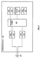
- FIG. 2 illustrates a
communication device 200 in an exemplary embodiment of the invention.Communication device 200 includes adigital interface system 202, a Plain Old Telephone Service (POTS)interface system 204, aprocessing system 206, adata interface system 208, aconversion system 210, and avoice interface system 212.Communication device 200 is configured to connect to at least onewireline 220.Wireline 220 may comprise a single twisted-pair copper wire.Wireline 220 may also comprise a twisted-pair copper wire and a coaxial cable. - In this embodiment,
digital interface system 202 connects towireline 220 andprocessing system 206.POTS interface system 204 connects towireline 220 andprocessing system 206.Processing system 206 connects todata interface system 208 andconversion system 210.Conversion system 210 connects to voiceinterface system 212. - In operation,
communication device 200 provides voice and data services. To provide the voice service or POTS service,POTS interface system 204 connects to a POTS provider overwireline 220. The POTS provider provides POTS service tocommunication device 200 through analog voice signals. The POTS provider may be a local telephone company or a central office of a telephone company. - For receiving a voice call into
communication device 200,POTS interface system 204 receives analog voice signals fromwireline 220.POTS interface system 204 converts the analog voice signals received overwireline 220 from analog format to digital format to generate digital voice signals.POTS interface system 204 transmits the digital voice signals toprocessing system 206.Processing system 206 performs an application on the digital voice signals to provide one or more presentation formats of the digital voice signals of the call to a user ofcommunication device 200. One example of a presentation format of the digital voice signals of the call includes displaying text of the call to the user. For instance, the digital voice signals of the call comprise bearer communications for the call. In this situation,processing system 206 performs the application on the digital voice signals to generate text of the digital voice signals and display the text to the user. Other presentation formats of the digital voice signals include printing or storing the text of the call.Processing system 206 may also perform another application on the digital voice signals to format the digital voice signals for wireless transmission to remote wireless devices. The wireless transmission may be for 802.1 b, 802.11 g, or another protocol. - To complete the voice call to the user,
processing system 206 forwards the digital voice signals toconversion system 210.Conversion system 210 converts the digital voice signals into analog voice signals and forwards the analog voice signals to voiceinterface system 212.Conversion system 210 may include a modulator/demodulator (modem) or Digital-to-Analog (D/A) circuitry.Voice interface system 212 transmits audible signals to the user representing the analog voice signals.Voice interface system 212 may include a microphone (not shown), a speaker (not shown), and a keypad (not shown). One example ofvoice interface system 212 may be a handset and keypad used for conventional phones. - For transmitting a voice call out of
communication device 200,voice interface system 212 receives audible signals from the user and forwards analog voice signals representing the audible signals toconversion system 210. The audible signals represent sounds spoken by the user.Conversion system 210 converts the analog voice signals into digital voice signals and forwards the digital voice signals toprocessing system 206.Processing system 206 performs the same or other applications on the digital voice signals to provide the presentation formats of the digital voice signals to the user.Processing system 206 forwards the digital voice signals toPOTS interface system 204.POTS interface system 204 converts the digital voice signals from digital format to analog format to generate analog voice signals.POTS interface system 204 transmits the analog voice signals overwireline 220. - Simultaneous with the voice service,
communication device 200 may provide data services. To provide the data services,digital interface system 202 connects to a data service provider overwireline 220. The data service provider provides the data service tocommunication device 200 through digital data signals. The data service provider may be an Internet Service Provider (ISP), a DSL provider, a cable television company offering Internet-based services, a server on the Internet, an email server, or another provider. - To receive data into
communication device 200,digital interface system 202 receives digital data signals overwireline 220.Digital interface system 202 forwards the digital data signals toprocessing system 206.Processing system 206 performs an application on the digital data signals to provide additional data to the user.Processing system 206 may provide the additional data throughdata interface system 208. Examples of providing the additional data include: displaying a telephone directory to assist in making a call, displaying text messages, such as SMS messages, displaying a web page or other data from the Internet, displaying additional or enhanced caller ID information, etc.Data interface system 208 may include a display, monitor, screen, or other display device.Data interface system 208 may also include a keyboard, a mouse or other pointing device, a keypad, or a touch-screen. -
Processing system 206 may also perform another application on the digital data signals to provide digital telephone service to the user. An example of digital telephone service is Voice over Internet Protocol (VoIP) service. - To transmit data out of
communication device 200,data interface system 208 receives input from the user. The input may be from a keyboard, a mouse or other pointing device, a keypad, or a touch-screen.Data interface system 208 generates digital data signals from the input and forwards the digital data signals toprocessing system 206.Processing system 206 performs the same or other applications on the digital data signals to provide additional data to the user.Processing system 206 forwards the digital data signals todigital interface system 202.Digital interface system 202 transmits the digital data signals overwireline 220 to the data service provider. -
Communication device 200 advantageously provides enhanced communications to the user by providing more features to the user with a single communication device. BecausePOTS interface system 204 digitizes the analog voice signals from the POTS provider,communication device 200 may provide different presentation formats to the user than previously available. For instance,communication device 200 may generate text from the digital voice signals and display the text to the user. The user can then read what was said in a conversation as the text of the conversation is displayed to the user. This may be useful for hearing impaired users. The user may also store part or all of the text of the conversation in a soft copy for future reference or print the text of the conversation in a hard copy.Communication device 200 may also format the digital voice signals for wireless transmission of the digital voice signals to remote wireless devices.Communication device 200 may format the digital voice signals based on 802.11 b, 802.11 g, or other protocols. The remote wireless devices may comprise wireless telephones or other wireless devices. -
Communication device 200 also advantageously integrates voice and data services into a single device. The data services may be used to enhance voice services incommunication device 200, and vice-versa. For instance, assume thatcommunication device 200 receives a video call. For the video call,POTS interface system 204,processing system 206,conversion system 210, andvoice interface system 212 may handle the voice-part of the call. In particular,processing system 206 performs an application on the digital voice signals of the call to provide voice for the call to the user. Simultaneously,digital interface system 202,processing system 206, anddata interface system 208 may handle the video-part of the call. In particular,processing system 206 performs an application on the digital data signals to provide video for the call to the user. The integration of the voice and data services provides the user with enhanced communications. - FIG. 3 and the following description depict specific exemplary embodiments of the invention to teach those skilled in the art how to make and use the invention. The invention is not limited to the specific embodiments described below, but only by the claims and their equivalents.
- FIG. 3 illustrates
communication device 200 in another exemplary embodiment of the invention. In this embodiment,communication device 200 also includes apower supply system 302, apower detection system 304, andPOTS circuitry 308.Power supply system 302 connects topower detection system 304.Power detection system 304 connects toPOTS circuitry 308. POTS circuitry connects towireline 220,POTS interface system 204, andvoice interface system 212. -
Power supply system 302 comprises any system, devices, or components configured to supply power tocommunication device 200.Power supply system 302 may comprise a battery that provides power tocommunication device 200.Power supply system 302 may comprise circuitry that connects to an external power source, such as a 110 Volt AC outlet. -
Communication device 200 operates substantially as described above in association with FIG. 2, except thatcommunication device 200 in FIG. 3 has the following added functionality.Power detection system 304 detects an interrupt in the power provided bypower supply system 302. The interrupt in power may be due to a problem withpower supply system 302 or a problem or outage with a commercial power source providing power topower supply system 302. The interrupt in power may be a temporary interrupt of a few seconds, or may be an extended interrupt of hours or days. - For voice calls coming into
communication device 200,POTS circuitry 308 receives analog voice signals from the POTS provider (not shown) overwireline 220.POTS circuitry 308 comprises conventional POTS circuitry used for POTS service. If power is interrupted tocommunication device 200, thenPOTS circuitry 308 forwards the analog voice signals to voiceinterface system 212. Responsive to the analog voice signals,voice interface system 212 transmits audible signals to the user. BecausePOTS circuitry 308 comprises traditional POTS circuitry,POTS circuitry 308 receives a low voltage signal from the POTS provider as is traditionally done. The low voltage signalpowers POTS circuitry 308 andvoice interface system 212 instead ofpower supply system 302. - If power is not interrupted to
communication device 200, thenPOTS circuitry 308 forwards the analog voice signals toPOTS interface system 204 andcommunication device 200 operates substantially as described above in association with FIG. 2. - For voice calls going out of
communication device 200,voice interface system 212 receives audible signals from the user. If power is interrupted tocommunication device 200, then voiceinterface system 212 forwards the analog voice signals, representing the audible signals, toPOTS circuitry 308. The audible signals represent sounds spoken by the user.POTS circuitry 308 forwards the analog voice signals overwireline 220. When the power is interrupted,POTS circuitry 308 does not transmit the analog voice signals toPOTS interface system 204 andPOTS interface system 204 does not convert the analog voice signals from analog format to digital format. - If power is not interrupted to
communication device 200, then voiceinterface system 212 forwards the analog voice signals toconversion system 210 andcommunication device 200 operates substantially as described above in association with FIG. 2. -
Communication device 200 advantageously is more reliable because it can operate when the power is interrupted. If the power tocommunication device 200 is interrupted, thencommunication device 200 advantageously reverts back to regular POTS service by havingPOTS circuitry 308 handle the call.POTS circuitry 308 is powered by the voltage put onwireline 220 by the central office and not bypower supply system 302. Therefore, the user may still make voice calls withcommunication device 200 when the power is interrupted. - FIG. 4 illustrates a
customer premises 402 coupled to acommunication network 404 in an exemplary embodiment of the invention.Customer premises 402 includes aterminal device 410.Communication network 404 includes acentral office 420, a Public Switched Telephone Network (PSTN) 422, an Internet Service Provider (ISP) 424, theInternet 426, a Voice over Internet Protocol (VoIP)server 428, andcontent servers 430.Central office 420 includesDSL system 440 andPOTS system 442. -
Customer premises 402 connects tocentral office 420 over a conventional twisted-pair copper wire 450.Central office 420 comprises the central office of a local telephone company. The connection betweencustomer premises 402 andcentral office 420 represents the "last mile" tocustomer premises 402.Central office 420 connects toPSTN 422 andISP 424.Central office 420 may connect toISP 424 throughPSTN 422 in some embodiments.ISP 424 connects to theInternet 426 and provides access to theInternet 426. Through theInternet 426,ISP 424 is able to connect toVoIP server 428 that provides VoIP service.ISP 424 is also able to connect tocontent servers 430, such as Yahoo!, Google, CNN, etc, through theInternet 426.ISP 424 may be able to connect to many other service and/or content providers. -
Central office 420 provides POTS service overwire 450 throughPOTS system 442.POTS system 442 comprises conventional circuitry and systems used to provide POTS service, such as a switch, a power supply, etc.Central office 420 also provides DSL service overwire 450 throughDSL system 440.DSL system 440 may include a Digital Subscriber Line Access Multiplexer (DSLAM) or other equipment.DSL system 442 may not be located incentral office 420 in other embodiments, ascentral office 420 may contract with another company or provider for the DSL service. - FIG. 5 illustrates the components of
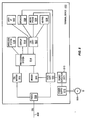
terminal device 410 in an exemplary embodiment of the invention.Terminal device 410 includes afilter 502, aDSL modem 504, amodem 506,power detection circuitry 510, apower supply 512, aprocessing system 514, awireless system 516, adisplay 518, Digital-to-Analog (D/A)circuitry 520, auser interface 522, aspeaker 524, amicrophone 526, akeypad 528, andPOTS circuitry 530. -
Filter 502 connects to wire 450.Filter 502 also connects toPOTS circuitry 530 andDSL modem 504.POTS circuitry 530 connects topower detection circuitry 510,modem 506,speaker 524,microphone 526, andkeypad 528.DSL modem 504 connects toprocessing system 514.Modem 506 connects toprocessing system 514.Processing system 514 connects towireless system 516,display 518,user interface 522, and D/A circuitry 520. D/A circuitry 520 connects tospeaker 524,microphone 526, andkeypad 528.Power detection circuitry 510 connects topower supply 512.Power supply 512 connects to acommercial power supply 550 to provide power toterminal device 410. -
Terminal device 410 is configured to provide voice and data services.Terminal device 410 receives POTS service fromPOTS system 442 overwire 450 for voice communications (see FIG. 4). Using the POTS service,terminal device 410 may receive and transmit voice calls.Terminal device 410 also receives DSL service fromDSL system 440 overwire 450 for data communications (see FIG. 4). Using the DSL service,terminal device 410 may receive and transmit data. - In operation,
filter 502 receives DSL signals overwire 450. DSL signals in this embodiment include analog POTS signals and digital signals.Filter 502 separates the analog POTS signals from the digital signals, forwards the analog POTS signals toPOTS circuitry 530, and forwards the digital signals toDSL modem 504. The analog POTS signals transferred toPOTS circuitry 530 represent traditional POTS service. The digital signals transferred toDSL modem 504 represent data services provided by the DSL service. - As a default for the POTS service,
POTS circuitry 530 forwards the analog POTS signals tomodem 506.Modem 506 receives the analog POTS signals and converts the analog POTS signals from analog format to digital format to generate digital POTS signals.Modem 506 transmits the digital POTS signals toprocessing system 514.Processing system 514 performs an application on the digital POTS signals to provide one or more presentation formats of the digital POTS signal to a user ofterminal device 410.Processing system 514 then forwards the digital POTS signals to D/A circuitry 520. D/A circuitry 520 converts the digital POTS signals again into analog POTS signals and transmits the analog POTS signals tospeaker 524. Responsive to the analog POTS signals,speaker 524 emits audible signals to a user representing the analog POTS signals. - Digitizing the analog POTS signals may allow
terminal device 410 to provide enhanced features to the user by providing multiple presentation formats of the digital POTS signals to the user. For instance,processing system 514 may generate text from the digital POTS signals and display the text to the user throughdisplay 518 or another data interface system. The user can then read what was said in a conversation as the text of the conversation is displayed to the user.Processing system 514 may also store part or all of the text of the conversation in a soft copy for future reference or print the text of the conversation in a hard copy. In storing or printing the text, understand thatprocessing system 514 may generate appropriate store or print commands to peripheral devices. -
Processing system 514 may perform any application that can be performed on digital signals or digital data to provide a useful or valuable feature to the user. For instance,processing system 514 may perform another application on the digital POTS signals to format the digital POTS signals for wireless communication.Processing system 514 may then transfers the digital POTS signals towireless system 516.Wireless system 516 may comprise an 802.11b hub or an 802.11g hub used for wireless transmission.Wireless system 516 can then transmit the digital POTS signals to remote wireless devices (not shown). The remote wireless devices may be wireless phones, wireless computers, Personal Digital Assistants (PDA), etc. - The components used to digitize the analog POTS signals require power from
power supply 512 to operate. For instance,modem 506,processing system 514, and D/A circuitry 520 need power frompower supply 512. Therefore,power detection circuitry 510 monitors the power provided bypower supply 512 and detects interrupts in the power. The interrupt in power may be due to a problem withpower supply 512 or a problem or outage withcommercial power supply 550. The interrupt in power may be a temporary interrupt of a few seconds, or may be an extended interrupt of hours or days. - If
power detection circuitry 510 detects an interrupt in power, thenPOTS circuitry 530 no longer forwards the analog POTS signals tomodem 506.Power detection circuitry 510 provides an instruction or control signal toPOTS circuitry 530 indicating that the power has been interrupted. Responsive to the instruction frompower detection circuitry 510 that power has been interrupted,POTS circuitry 530 handles the call.POTS circuitry 530 comprises conventional POTS circuitry used for POTS service.POTS circuitry 530 handles the analog POTS signals in a conventional manner and forwards the analog POTS signals tospeaker 524. Responsive to the analog POTS signals,speaker 524 emits audible signals to a user representing the analog POTS signals. - Because
POTS circuitry 530 is connected to the POTS service,POTS circuitry 530 receives a low voltage signal fromcentral office 420 in FIG. 4. The low voltage signalpowers POTS circuitry 530 instead ofpower supply 512.POTS circuitry 530 may not be able to provide the enhanced services as can be done by digitizing the analog POTS signals. However,POTS circuitry 530 is able to operate even if power is interrupted toterminal device 410 so that the user may still make and receive calls. - The user may also make a call using
terminal device 410. The user enters anumber using keypad 528. The user may also enter a number by selecting a number displayed ondisplay 518, enter a number throughuser interface 522, etc. Depending on whether power has been interrupted toterminal device 410,terminal device 410 places the call throughPOTS circuitry 530 orprocessing system 514. -
Terminal device 410 also provides high speed data service to the user through DSL service. For DSL service,DSL modem 504 receives the digital signals fromfilter 502.DSL modem 504 forwards the digital signals toprocessing system 514.Processing system 514 performs an application on the digital signals to provide additional data to the user. For instance, the digital signals may carry an HTML file for a web site.Processing system 514 may then display the web site to the user throughdisplay 518. -
Terminal device 410 may also transmit data using the DSL service. The user may input data usinguser interface 522. The data may be inputted from a keyboard, a mouse or other pointing device, a keypad, or a touch-screen.Processing system 514 receives the input and processes the input.Processing system 514 may run one or more applications based on the input to generate digital signals.Processing system 514 forwards the digital signals toDSL modem 504.DSL modem 504 forwards the digital signals to filter 502. - The DSL service allows the user to surf the Internet, send and receive emails, etc. The DSL service advantageously provides a high speed connection to the
Internet 426 through ISP 424 (see FIG. 4). The DSL service may also be used to further enhance a voice call to the user or to provide other features for the user. For instance, DSL service may allowterminal device 410 to receive and transmit Short Message Service (SMS) messages. The DSL service may also allow the user to download a telephone directory from theInternet 426. - The user may also make calls using the DSL service. If the user subscribes to VoIP service, then processing
system 514 runs some type of VoIP software. The VoIP software allows the user to enter a phone number. The VoIP software uses the high speed DSL service to connect withVoIP server 428 through ISP 424 (see FIG. 4).VoIP server 428 locates a terminating node for the phone number and establishes an IP address for the terminating point for the call.VoIP server 428 transmits the IP address to the VoIP software running onprocessing system 514. With the call set up, the user may then talk intomicrophone 526. The VoIP software converts the user's voice captured bymicrophone 526 into digital signals. The VoIP software then transmits the digital signals overwire 450 at the high frequency of the DSL service. The VoIP software transmits the digital signals to the terminating point based on the IP address of the terminating point. The digital signals travel over theInternet 426 to the terminating point. - In this embodiment of the invention, DSL service is used. In other embodiments, other data services may be used in conjunction with the POTS service. For instance,
terminal device 410 may include a cable modem in another embodiment to receive a cable data service in addition to the POTS service. - FIG. 6 illustrates the interfaces of
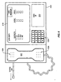
terminal device 410 in an exemplary embodiment of the invention.Terminal device 410 includes ahandset 602,display 518,user interface 522, andkeypad 528.Handset 602 includesspeaker 524 andmicrophone 526.Terminal device 410 may also include other features, such as a wireless antenna for 802.11b or 802.11g communications. This view ofterminal device 410 is just one embodiment.Terminal device 410 may look more like a computer than a telephone in other embodiments.Speaker 524 andmicrophone 526 may not be included inhandset 602 in other embodiments. -
Terminal device 410 allows the user to make calls, surf the Internet, send and receive emails, etc. Assume the user wants to make a call.Display 518 displays a home calling page to the user. The home calling page is customized for the user.Terminal device 410 may store the home calling page, orterminal device 410 may download the home calling page from the Internet 426 (see FIG. 4). The home calling page includes a list of contacts frequently called by the user. The list may also include phone numbers, email addresses, and other information on the contacts. There may be many other contacts listed than those shown in FIG. 6. The contacts list may correspond with email software used interminal device 410, such as Microsoft Outlook. - The user selects one of the contacts in the contact list. The user may select the contact using a mouse, a keyboard, a touch screen, etc. The user may select whether the call is an audio call or a video call. Responsive to selecting the contact,
terminal device 410 places the call.Terminal device 410 may place the call using POTS service or VoIP service. The user may be unaware of the service used byterminal device 410. - The user may also enter a telephone number manually using
keypad 528.Keypad 528 may be used to dial new numbers.Keypad 528 may also be used if power is interrupted toterminal device 410. As shown in FIG. 5,keypad 528,speaker 524, andmicrophone 526 are powered by the POTS service throughPOTS circuitry 530. Therefore, the user may useterminal device 410 when the power is interrupted. - When the call is connected,
terminal device 410 may display a text version of the call ondisplay 518.Terminal device 410 is able to provide the text version because it digitizes the analog POTS signals. The user may be able to store all or a portion of the text version of the call for future reference. The user may also print all or a portion of the text version. - Through DSL service, the user can surf the
Internet 426 and make calls simultaneously. Assume thatterminal device 410 is logged on toISP 424 in FIG. 4.ISP 424 providesterminal device 410 access to theInternet 426. With the call connected, the user may select the "Web Browser" icon. The web browser may link to a search engine, such as Yahoo! or Google, or may link to another web site designated by the user. Throughuser interface 522 anddisplay 518, the user may then surf theInternet 426. - Through the DSL service, the user may also receive other features of communication. In one example, the user may receive text messages that are displayed on
display 518. The user may receive the Short Message Service (SMS) messages from cell phones or other wireless devices. The user may also transmit text messages throughuser interface 522. In another example,terminal device 518 may download a telephone directory from theInternet 426 to assist the user in placing a call. -
Terminal device 410 advantageously combines voice services and data services to provide enhanced features for the user. Features from the data services may be used to enhance the voice services, and vice-versa, to give new and valuable options to the user.
Claims (10)
- A communication device (200) configured to connect to at least one wireline (220), the communication device comprising:a digital interface system (202) configured to receive digital data signals from a data service provider over the at least one wireline, and forward the digital data signals; anda processing system, responsive to receiving the digital data signals, performs an application on the digital data signals to provide data to the user;the communication device characterized by:a POTS interface system (204) configured to receive analog voice signals for a call from a POTS provider over the at least one wireline;the POTS interface system, responsive to receiving the analog voice signals for the call, converts the analog voice signals received over the at least one wireline from analog format to digital format to generate digital voice signals, and forwards the digital voice signals;the processing system (206), responsive to receiving the digital voice signals, performs an application on the digital voice signals to provide at least one presentation format of the digital voice signals of the call to a user;a conversion system (210), responsive to receiving the digital voice signals, converts the digital voice signals into analog voice signals and forwards the analog voice signals; anda voice interface system (212), responsive to receiving the analog voice signals from the conversion system, transmits audible signals to the user representing the analog voice signals.
- The communication device (200) of claim 1 wherein:the digital voice signals of the call comprise bearer communications for the call; andthe processing system (206), responsive to receiving the digital voice signals, performs the application on the digital voice signals to generate text of the bearer communications for the call and display the text to the user through a data interface system (208).
- The communication device (200) of claim 1 wherein:the processing system (206), responsive to receiving the digital data signals, performs the application on the digital data signals to display a web page to the user.
- The communication device (200) of claim 1 wherein:the processing system (206), responsive to receiving the digital voice signals, performs the application on the digital voice signals to provide voice for the call to the user; andthe processing system, responsive to receiving the digital data signals, performs the application on the digital data signals to provide video for the call to the user.
- The communication device (200) of claim 1 wherein the communication device (200) further comprises:a power supply system (302) that provides power to the communication device;power detection system (304) that detects an interrupt in the power provided by the power supply system; andPOTS circuitry (308) configured to receive the analog voice signals and transfer the analog voice signals to the voice interface system (212),the POTS circuitry, responsive to the power detection system detecting an interrupt in power, transmits the analog voice signals to the POTS interface system (204) instead of the voice interface system.
- A method of operating a communication device (200) configured to connect to at least one wireline (220), the method comprising the steps of:receiving digital data signals from a data service provider over the at least one wireline, andperforming an application on the digital data signals to provide data to the user,the method characterized by the steps of:receiving analog voice signals for a call from a POTS provider over the at least one wireline,converting the analog voice signals received over the at least one wireline from analog format to digital format to generate digital voice signals,performing an application on the digital voice signals to provide at least one presentation format of the digital voice signals of the call to a user,converting the digital voice signals into analog voice signals, andtransmitting audible signals to the user representing the analog voice signals.
- The method of claim 6 wherein the digital voice signals of the call comprise bearer communications for the call, and wherein the step of performing an application on the digital voice signals to provide at least one presentation format of the digital voice signals to a user comprises:generating text of the bearer communications for the call; anddisplaying the text to the user.
- The method of claim 6 wherein the step of performing an application on the digital data signals to provide additional data to the user comprises:displaying a web page to the user.
- The method of claim 6 further comprising the steps of:performing the application on the digital voice signals to provide voice for the call to the user; andperforming the application on the digital data signals to provide video for the call to the user.
- The method of claim 6 further comprising:detecting an interrupt in the power provided to the communication device, andconverting the analog voice signals from analog format to digital format to generate digital voice signals responsive to not detecting an interrupt in the power, andnot converting the analog voice signals from analog format to digital format responsive to detecting an interrupt in the power.
Applications Claiming Priority (2)
| Application Number | Priority Date | Filing Date | Title |
|---|---|---|---|
| US10/717,889 US7050553B2 (en) | 2003-11-20 | 2003-11-20 | Communication device that provides enhanced services |
| US717889 | 2003-11-20 |
Publications (2)
| Publication Number | Publication Date |
|---|---|
| EP1533986A2 true EP1533986A2 (en) | 2005-05-25 |
| EP1533986A3 EP1533986A3 (en) | 2005-06-15 |
Family
ID=34435768
Family Applications (1)
| Application Number | Title | Priority Date | Filing Date |
|---|---|---|---|
| EP04256861A Ceased EP1533986A3 (en) | 2003-11-20 | 2004-11-05 | Communication device that provides enhanced services |
Country Status (5)
| Country | Link |
|---|---|
| US (1) | US7050553B2 (en) |
| EP (1) | EP1533986A3 (en) |
| JP (1) | JP4526931B2 (en) |
| KR (1) | KR101091698B1 (en) |
| CN (1) | CN1642134A (en) |
Families Citing this family (8)
| Publication number | Priority date | Publication date | Assignee | Title |
|---|---|---|---|---|
| US20050125541A1 (en) * | 2003-12-04 | 2005-06-09 | Randall Frank | Integrating multiple communication modes |
| WO2006066610A1 (en) * | 2004-12-23 | 2006-06-29 | Telecom Italia S.P.A. | Method and system for video telephone communications set up, related equipment and computer program product |
| US20070211886A1 (en) * | 2006-03-09 | 2007-09-13 | Adams Thomas H | Phone converter system |
| US20070286173A1 (en) * | 2006-05-23 | 2007-12-13 | Bayhub, Inc | Interactive console for delivering digital network services to telephone networks |
| US7782907B2 (en) * | 2006-09-12 | 2010-08-24 | Broadcom Corporation | DSL modems with analog voice band support |
| CN102348026B (en) * | 2010-07-30 | 2013-09-04 | 国基电子(上海)有限公司 | Telephone network communication device and network switching method |
| JP5877351B2 (en) * | 2010-12-15 | 2016-03-08 | パナソニックIpマネジメント株式会社 | Communication apparatus and communication method |
| US10147415B2 (en) | 2017-02-02 | 2018-12-04 | Microsoft Technology Licensing, Llc | Artificially generated speech for a communication session |
Citations (4)
| Publication number | Priority date | Publication date | Assignee | Title |
|---|---|---|---|---|
| US4882681A (en) * | 1987-09-02 | 1989-11-21 | Brotz Gregory R | Remote language translating device |
| EP0740451A1 (en) * | 1995-04-24 | 1996-10-30 | ALCATEL BELL Naamloze Vennootschap | Method, interface modules and telephone network for multiplexing and demultiplexing an analog MTS (message telephone service) signal and an ADSL (asymmetric digital subscriber line) datastream |
| US6138096A (en) * | 1996-11-26 | 2000-10-24 | Add Value Holdings Pte Ltd. | Apparatus for speech-based generation, audio translation, and manipulation of text messages over voice lines |
| WO2001017219A1 (en) * | 1999-09-01 | 2001-03-08 | Catena Networks, Inc. | Enhanced line card and packetizing cpe for lifeline packet voice telephone |
Family Cites Families (15)
| Publication number | Priority date | Publication date | Assignee | Title |
|---|---|---|---|---|
| DE3135251A1 (en) | 1981-09-05 | 1983-03-17 | Basf Ag, 6700 Ludwigshafen | THERMOPLASTIC MOLDING |
| JPS6356853U (en) * | 1986-10-02 | 1988-04-15 | ||
| JPH03165155A (en) * | 1989-11-22 | 1991-07-17 | Omron Corp | Telephone set for person of hard of hearing |
| US6546005B1 (en) * | 1997-03-25 | 2003-04-08 | At&T Corp. | Active user registry |
| JPH11284766A (en) * | 1998-03-31 | 1999-10-15 | Japan Aviation Electronics Ind Ltd | Branching/coupling device for pots signal and dsl signal of telephone line |
| US6345047B1 (en) * | 1998-06-12 | 2002-02-05 | Northern Telecom Limited | Computer telephony adapter and method |
| US6490550B1 (en) * | 1998-11-30 | 2002-12-03 | Ericsson Inc. | System and method for IP-based communication transmitting speech and speech-generated text |
| KR100607140B1 (en) * | 2000-02-29 | 2006-08-02 | 유니데이타커뮤니케이션 주식회사 | Internet based telephone apparatus |
| CN1452836A (en) * | 2000-05-22 | 2003-10-29 | 印菲内奥技术股份有限公司 | Integrated telephone set with xDSL-modem |
| JP2002281469A (en) * | 2001-03-21 | 2002-09-27 | Canon Inc | Video telephone system |
| JP2002314646A (en) * | 2001-04-10 | 2002-10-25 | Shinsedai Kk | Telephone set |
| WO2002100083A1 (en) * | 2001-06-04 | 2002-12-12 | Sharp Kabushiki Kaisha | Internet telephone apparatus and internet telephone system |
| JP2003099081A (en) * | 2001-09-26 | 2003-04-04 | Sanyo Electric Co Ltd | Voice transmitter-receiver |
| JP3733886B2 (en) * | 2001-09-28 | 2006-01-11 | ブラザー工業株式会社 | Communication device, program, recording medium |
| JP2003195885A (en) * | 2001-12-25 | 2003-07-09 | Canon Inc | Communication device and its control method |
-
2003
- 2003-11-20 US US10/717,889 patent/US7050553B2/en not_active Expired - Lifetime
-
2004
- 2004-11-05 EP EP04256861A patent/EP1533986A3/en not_active Ceased
- 2004-11-12 KR KR1020040092299A patent/KR101091698B1/en not_active IP Right Cessation
- 2004-11-19 CN CNA2004100952256A patent/CN1642134A/en active Pending
- 2004-11-19 JP JP2004335320A patent/JP4526931B2/en not_active Expired - Fee Related
Patent Citations (4)
| Publication number | Priority date | Publication date | Assignee | Title |
|---|---|---|---|---|
| US4882681A (en) * | 1987-09-02 | 1989-11-21 | Brotz Gregory R | Remote language translating device |
| EP0740451A1 (en) * | 1995-04-24 | 1996-10-30 | ALCATEL BELL Naamloze Vennootschap | Method, interface modules and telephone network for multiplexing and demultiplexing an analog MTS (message telephone service) signal and an ADSL (asymmetric digital subscriber line) datastream |
| US6138096A (en) * | 1996-11-26 | 2000-10-24 | Add Value Holdings Pte Ltd. | Apparatus for speech-based generation, audio translation, and manipulation of text messages over voice lines |
| WO2001017219A1 (en) * | 1999-09-01 | 2001-03-08 | Catena Networks, Inc. | Enhanced line card and packetizing cpe for lifeline packet voice telephone |
Also Published As
| Publication number | Publication date |
|---|---|
| US20050111638A1 (en) | 2005-05-26 |
| JP2005168009A (en) | 2005-06-23 |
| CN1642134A (en) | 2005-07-20 |
| KR101091698B1 (en) | 2011-12-08 |
| JP4526931B2 (en) | 2010-08-18 |
| US7050553B2 (en) | 2006-05-23 |
| EP1533986A3 (en) | 2005-06-15 |
| KR20050049351A (en) | 2005-05-25 |
Similar Documents
| Publication | Publication Date | Title |
|---|---|---|
| US9112953B2 (en) | Internet telephony unit and software for enabling internet telephone access from traditional telephone interface | |
| US6665375B1 (en) | Method and apparatus for providing accessibility to call connection status | |
| JP3628962B2 (en) | Internet call waiting | |
| US6519246B1 (en) | Internet-enabled voice-response service | |
| US6215863B1 (en) | Method and apparatus for providing a station set with advanced telecommunications services | |
| US7565115B2 (en) | Communication system for landline and wireless calls | |
| US20080144611A1 (en) | Communication method and system for internet phone | |
| KR100368114B1 (en) | Telephone system using internet | |
| US20030076817A1 (en) | Apparatus and method for interfacing internet telephone | |
| US7050553B2 (en) | Communication device that provides enhanced services | |
| KR20060018232A (en) | Method and apparatus for stand-alone voice over internet protocol with pots telephone support | |
| US20070070985A1 (en) | System and Method for Integrating Internet Phone to Ordinary Phone | |
| JP4272379B2 (en) | Method and system for providing telephone service and article | |
| US20070093205A1 (en) | Wireless networking communication system and communicating method for VOIP | |
| US20070286173A1 (en) | Interactive console for delivering digital network services to telephone networks | |
| WO2005050962A1 (en) | Audio communication system and server apparatus | |
| US8249053B2 (en) | Voice communication system | |
| KR100219652B1 (en) | Apparatus and method for transmitting/receiving a call in the internet connection mode | |
| US20070253440A1 (en) | Internet communication system and method | |
| WO2002009372A1 (en) | Internet video phone | |
| US20020191587A1 (en) | Communication system | |
| EP1892933B1 (en) | Home gateway containing Voip, PSTN and POTS interfaces | |
| KR20050119887A (en) | Call control apparatus and operation method thereof | |
| KR200194545Y1 (en) | Connecting device for wire/wireless telephone with internet | |
| KR101087728B1 (en) | Internet Protocol phone and system for providing a presence service, and method thereof |
Legal Events
| Date | Code | Title | Description |
|---|---|---|---|
| PUAI | Public reference made under article 153(3) epc to a published international application that has entered the european phase |
Free format text: ORIGINAL CODE: 0009012 |
|
| PUAL | Search report despatched |
Free format text: ORIGINAL CODE: 0009013 |
|
| 17P | Request for examination filed |
Effective date: 20041123 |
|
| AK | Designated contracting states |
Kind code of ref document: A2 Designated state(s): AT BE BG CH CY CZ DE DK EE ES FI FR GB GR HU IE IS IT LI LU MC NL PL PT RO SE SI SK TR |
|
| AX | Request for extension of the european patent |
Extension state: AL HR LT LV MK YU |
|
| AK | Designated contracting states |
Kind code of ref document: A3 Designated state(s): AT BE BG CH CY CZ DE DK EE ES FI FR GB GR HU IE IS IT LI LU MC NL PL PT RO SE SI SK TR |
|
| AX | Request for extension of the european patent |
Extension state: AL HR LT LV MK YU |
|
| 17Q | First examination report despatched |
Effective date: 20050523 |
|
| AKX | Designation fees paid | ||
| RBV | Designated contracting states (corrected) |
Designated state(s): DE FR GB |
|
| REG | Reference to a national code |
Ref country code: DE Ref legal event code: 8566 |
|
| STAA | Information on the status of an ep patent application or granted ep patent |
Free format text: STATUS: THE APPLICATION HAS BEEN REFUSED |
|
| 18R | Application refused |
Effective date: 20070525 |