EP1534176B1 - Composite sling for treating incontinence - Google Patents
Composite sling for treating incontinence Download PDFInfo
- Publication number
- EP1534176B1 EP1534176B1 EP03793021A EP03793021A EP1534176B1 EP 1534176 B1 EP1534176 B1 EP 1534176B1 EP 03793021 A EP03793021 A EP 03793021A EP 03793021 A EP03793021 A EP 03793021A EP 1534176 B1 EP1534176 B1 EP 1534176B1
- Authority
- EP
- European Patent Office
- Prior art keywords
- sling
- patient
- biomaterial
- urethra
- segments
- Prior art date
- Legal status (The legal status is an assumption and is not a legal conclusion. Google has not performed a legal analysis and makes no representation as to the accuracy of the status listed.)
- Expired - Lifetime
Links
Images


Classifications
-
- A—HUMAN NECESSITIES
- A61—MEDICAL OR VETERINARY SCIENCE; HYGIENE
- A61F—FILTERS IMPLANTABLE INTO BLOOD VESSELS; PROSTHESES; DEVICES PROVIDING PATENCY TO, OR PREVENTING COLLAPSING OF, TUBULAR STRUCTURES OF THE BODY, e.g. STENTS; ORTHOPAEDIC, NURSING OR CONTRACEPTIVE DEVICES; FOMENTATION; TREATMENT OR PROTECTION OF EYES OR EARS; BANDAGES, DRESSINGS OR ABSORBENT PADS; FIRST-AID KITS
- A61F2/00—Filters implantable into blood vessels; Prostheses, i.e. artificial substitutes or replacements for parts of the body; Appliances for connecting them with the body; Devices providing patency to, or preventing collapsing of, tubular structures of the body, e.g. stents
- A61F2/0004—Closure means for urethra or rectum, i.e. anti-incontinence devices or support slings against pelvic prolapse
- A61F2/0031—Closure means for urethra or rectum, i.e. anti-incontinence devices or support slings against pelvic prolapse for constricting the lumen; Support slings for the urethra
- A61F2/0036—Closure means for urethra or rectum, i.e. anti-incontinence devices or support slings against pelvic prolapse for constricting the lumen; Support slings for the urethra implantable
- A61F2/0045—Support slings
-
- A—HUMAN NECESSITIES
- A61—MEDICAL OR VETERINARY SCIENCE; HYGIENE
- A61B—DIAGNOSIS; SURGERY; IDENTIFICATION
- A61B17/00—Surgical instruments, devices or methods, e.g. tourniquets
- A61B17/04—Surgical instruments, devices or methods, e.g. tourniquets for suturing wounds; Holders or packages for needles or suture materials
- A61B17/0401—Suture anchors, buttons or pledgets, i.e. means for attaching sutures to bone, cartilage or soft tissue; Instruments for applying or removing suture anchors
-
- A—HUMAN NECESSITIES
- A61—MEDICAL OR VETERINARY SCIENCE; HYGIENE
- A61B—DIAGNOSIS; SURGERY; IDENTIFICATION
- A61B17/00—Surgical instruments, devices or methods, e.g. tourniquets
- A61B17/04—Surgical instruments, devices or methods, e.g. tourniquets for suturing wounds; Holders or packages for needles or suture materials
- A61B17/0487—Suture clamps, clips or locks, e.g. for replacing suture knots; Instruments for applying or removing suture clamps, clips or locks
-
- A—HUMAN NECESSITIES
- A61—MEDICAL OR VETERINARY SCIENCE; HYGIENE
- A61B—DIAGNOSIS; SURGERY; IDENTIFICATION
- A61B17/00—Surgical instruments, devices or methods, e.g. tourniquets
- A61B17/04—Surgical instruments, devices or methods, e.g. tourniquets for suturing wounds; Holders or packages for needles or suture materials
- A61B17/06—Needles ; Sutures; Needle-suture combinations; Holders or packages for needles or suture materials
- A61B17/06004—Means for attaching suture to needle
-
- A—HUMAN NECESSITIES
- A61—MEDICAL OR VETERINARY SCIENCE; HYGIENE
- A61B—DIAGNOSIS; SURGERY; IDENTIFICATION
- A61B17/00—Surgical instruments, devices or methods, e.g. tourniquets
- A61B17/04—Surgical instruments, devices or methods, e.g. tourniquets for suturing wounds; Holders or packages for needles or suture materials
- A61B17/06—Needles ; Sutures; Needle-suture combinations; Holders or packages for needles or suture materials
- A61B17/06066—Needles, e.g. needle tip configurations
- A61B17/06109—Big needles, either gripped by hand or connectable to a handle
-
- A—HUMAN NECESSITIES
- A61—MEDICAL OR VETERINARY SCIENCE; HYGIENE
- A61B—DIAGNOSIS; SURGERY; IDENTIFICATION
- A61B17/00—Surgical instruments, devices or methods, e.g. tourniquets
- A61B17/04—Surgical instruments, devices or methods, e.g. tourniquets for suturing wounds; Holders or packages for needles or suture materials
- A61B17/06—Needles ; Sutures; Needle-suture combinations; Holders or packages for needles or suture materials
- A61B17/062—Needle manipulators
-
- A—HUMAN NECESSITIES
- A61—MEDICAL OR VETERINARY SCIENCE; HYGIENE
- A61B—DIAGNOSIS; SURGERY; IDENTIFICATION
- A61B17/00—Surgical instruments, devices or methods, e.g. tourniquets
- A61B17/04—Surgical instruments, devices or methods, e.g. tourniquets for suturing wounds; Holders or packages for needles or suture materials
- A61B17/0469—Suturing instruments for use in minimally invasive surgery, e.g. endoscopic surgery
-
- A—HUMAN NECESSITIES
- A61—MEDICAL OR VETERINARY SCIENCE; HYGIENE
- A61B—DIAGNOSIS; SURGERY; IDENTIFICATION
- A61B17/00—Surgical instruments, devices or methods, e.g. tourniquets
- A61B17/04—Surgical instruments, devices or methods, e.g. tourniquets for suturing wounds; Holders or packages for needles or suture materials
- A61B17/0482—Needle or suture guides
-
- A—HUMAN NECESSITIES
- A61—MEDICAL OR VETERINARY SCIENCE; HYGIENE
- A61B—DIAGNOSIS; SURGERY; IDENTIFICATION
- A61B17/00—Surgical instruments, devices or methods, e.g. tourniquets
- A61B17/04—Surgical instruments, devices or methods, e.g. tourniquets for suturing wounds; Holders or packages for needles or suture materials
- A61B17/06—Needles ; Sutures; Needle-suture combinations; Holders or packages for needles or suture materials
- A61B17/06066—Needles, e.g. needle tip configurations
-
- A—HUMAN NECESSITIES
- A61—MEDICAL OR VETERINARY SCIENCE; HYGIENE
- A61B—DIAGNOSIS; SURGERY; IDENTIFICATION
- A61B17/00—Surgical instruments, devices or methods, e.g. tourniquets
- A61B17/30—Surgical pincettes without pivotal connections
-
- A—HUMAN NECESSITIES
- A61—MEDICAL OR VETERINARY SCIENCE; HYGIENE
- A61B—DIAGNOSIS; SURGERY; IDENTIFICATION
- A61B17/00—Surgical instruments, devices or methods, e.g. tourniquets
- A61B17/32—Surgical cutting instruments
- A61B17/3209—Incision instruments
- A61B17/3211—Surgical scalpels, knives; Accessories therefor
-
- A—HUMAN NECESSITIES
- A61—MEDICAL OR VETERINARY SCIENCE; HYGIENE
- A61B—DIAGNOSIS; SURGERY; IDENTIFICATION
- A61B17/00—Surgical instruments, devices or methods, e.g. tourniquets
- A61B2017/00743—Type of operation; Specification of treatment sites
- A61B2017/00805—Treatment of female stress urinary incontinence
-
- A—HUMAN NECESSITIES
- A61—MEDICAL OR VETERINARY SCIENCE; HYGIENE
- A61B—DIAGNOSIS; SURGERY; IDENTIFICATION
- A61B17/00—Surgical instruments, devices or methods, e.g. tourniquets
- A61B17/04—Surgical instruments, devices or methods, e.g. tourniquets for suturing wounds; Holders or packages for needles or suture materials
- A61B17/06—Needles ; Sutures; Needle-suture combinations; Holders or packages for needles or suture materials
- A61B17/06004—Means for attaching suture to needle
- A61B2017/06009—Means for attaching suture to needle having additional means for releasably clamping the suture to the needle, e.g. actuating rod slideable within the needle
-
- A—HUMAN NECESSITIES
- A61—MEDICAL OR VETERINARY SCIENCE; HYGIENE
- A61B—DIAGNOSIS; SURGERY; IDENTIFICATION
- A61B17/00—Surgical instruments, devices or methods, e.g. tourniquets
- A61B17/04—Surgical instruments, devices or methods, e.g. tourniquets for suturing wounds; Holders or packages for needles or suture materials
- A61B17/06—Needles ; Sutures; Needle-suture combinations; Holders or packages for needles or suture materials
- A61B17/06004—Means for attaching suture to needle
- A61B2017/06042—Means for attaching suture to needle located close to needle tip
-
- A—HUMAN NECESSITIES
- A61—MEDICAL OR VETERINARY SCIENCE; HYGIENE
- A61B—DIAGNOSIS; SURGERY; IDENTIFICATION
- A61B17/00—Surgical instruments, devices or methods, e.g. tourniquets
- A61B17/04—Surgical instruments, devices or methods, e.g. tourniquets for suturing wounds; Holders or packages for needles or suture materials
- A61B17/06—Needles ; Sutures; Needle-suture combinations; Holders or packages for needles or suture materials
- A61B17/06066—Needles, e.g. needle tip configurations
- A61B2017/06085—Needles, e.g. needle tip configurations having a blunt tip
-
- A—HUMAN NECESSITIES
- A61—MEDICAL OR VETERINARY SCIENCE; HYGIENE
- A61B—DIAGNOSIS; SURGERY; IDENTIFICATION
- A61B50/00—Containers, covers, furniture or holders specially adapted for surgical or diagnostic appliances or instruments, e.g. sterile covers
- A61B50/30—Containers specially adapted for packaging, protecting, dispensing, collecting or disposing of surgical or diagnostic appliances or instruments
-
- A—HUMAN NECESSITIES
- A61—MEDICAL OR VETERINARY SCIENCE; HYGIENE
- A61B—DIAGNOSIS; SURGERY; IDENTIFICATION
- A61B90/00—Instruments, implements or accessories specially adapted for surgery or diagnosis and not covered by any of the groups A61B1/00 - A61B50/00, e.g. for luxation treatment or for protecting wound edges
- A61B90/02—Devices for expanding tissue, e.g. skin tissue
Definitions
- Urinary incontinence is a significant health concern worldwide. Millions of people worldwide suffer from this problem. There are many different forms of incontinence. One of the most common is known as stress urinary incontinence (hereafter SUI).
- SUI stress urinary incontinence
- a pubovaginal sling procedure is a surgical method involving the placement of a sling to stabilize or support the bladder neck or urethra.
- Slings for treating incontinence may be constructed from synthetic materials such as polypropylene, polytetrafluoroethylene, polyester and silicone.
- Slings constructed from non-synthetic materials include allografts, homografts, heterografts, autologous tissues, cadaveric fascia and fascia lata. The strength and other properties of certain non-synthetic sling materials have been reported in the literature. See, Chaikin et al., Weakened Cadaveric Fascial Sling: An Unexpected Cause of Failure, Journal of Urology, Vol. 160, 2151 (Dec.
- non-synthetic materials for slings varies greatly. Certain sizes of non-synthetic materials can be especially difficult to secure in a timely fashion. For example, autologous material may be difficult or impossible to harvest from some patients due to a variety of factors, including the health of the patient and the size of the tissue needed for a sling.
- IVS Intravaginal Slingplasty
- Some pubovaginal sling procedures extend a sling from the rectus fascia in the abdominal region, to a position below the urethra, and back again to the rectus fascia. Some slings are anchored in the abdominal fascia by virtue of suturing the sling material to the patient' abdominal tissue (e.g. rectus fascia). See Blaivas, Commentary: Pubovaginal Sling Procedure, Current Operative Urology, Edited by E.D. Whitehead, Philadelphia: J.B. Lippincott Co. Pp. 93-100 (1990 ) (biologic sling); and Moir, The Gauze-Hammock Operation, The Journal of Obstetrics and Gynaecology of the British Commonwealth, Vol.
- the Tension-free Vaginal Tape (TVT) procedure utilizes a ProleneTM nonabsorbable, polypropylene mesh.
- the TVT mesh extends from the rectus fascia in the abdominal region, to a position below the urethra, and back again to the rectus fascia. No suture is recommended to tie the end of the mesh to the rectus fascia.
- Problems with the TVT procedure are documented in the literature and patents. See PCT publication nos. PCT WO 00/74613 and PCT WO 00/74594 , U.S. Pat. Nos. 6,273,852 ; 6,406,423 ; and 6,478,727 , and published U.S. Pat.
- WO 00/74633 discloses a tape for treating SUI.
- the tape is a combination of synthetic materials and a natural material centered between the synthetic materials.
- the natural material may be placed over or incorporated within a generally central portion of the synthetic material.
- the natural material may be connected to the synthetic material by sewing, a bio-compatible glue or cell culturing techniques.
- U.S. Pat. No. 6,306,079 discloses a mesh pubovaginal sling comprising two pieces.
- One piece comprises a polypropylene mesh and a second mesh portion comprises an absorbable material such as poly-dioxanone.
- One piece may be inserted at the endopelvic fascia and the other in the suprapubic region. The two pieces are then connected via suture to support prolapsed organs so as to relieve urinary stress incontinence.
- U.S. Pat. No. 6,355,065 discloses an implantable support that may be used in suburethral stabilization procedures for reducing stress incontinence. Ends of the support are folded to reinforce suture holes and to inhibit fraying or rupturing. Threading mechanisms may be provided to facilitate threading of sutures through suture holes. A removable, elongated clip may be placed on an intermediate portion of the implant to inhibit folding of the implant about its longitudinal axis. This document speculates that longitudinal folding of the implant could cause dead space in which bacteria could collect.
- U.S. Pat No. 6,042,534 discloses a stabilization sling for use in minimally invasive pelvic surgery.
- the sling may include reinforced suture receiving sites. Ends of the sling may be folded over to reinforce the sling.
- PCT International Publication No. WO 02/28312 discloses a sub-urethral supporting assembly for treating female SUI.
- a junction part is disclosed for connecting two ends of a support tape.
- Published U.S. Pat Application No. 2002/0028980 discloses a Y-shaped implantable article for use in a sacral colpopexy procedure.
- Published U.S. Pat Application No. 2002/0082619 discloses a reinforcing fastener guide for enhancing the functional longevity of an implant such as a sling.
- WO 02/058564 A2 describes an implantable sling assembly for treating medical disorders, wherein the sling assembly may be constructed from a synthetic material and a non-synthetic material. It is an assembly for use in constructing a composite sling for treating a patient's incontinence, the assembly comprising:
- the invention comprises an assembly of components for use in constructing a composite sling for treating a patient's incontinence.
- the assembly comprises a first segment comprising a synthetic material having a distal end and an attachment end; a second segment comprising a synthetic material having a distal end and an attachment end; a biomaterial ; and an integrator for associating the biomaterial with the attachment ends of the first and second segments so that the biomaterial may be placed underneath the patient's urethra.
- the first and second segments are specially sized and shaped.
- They may be sized and shaped to extend from a position substantially adjacent the patient's urethra to a position substantially adjacent the patient's rectus fascia so that the first and second segments and the biomaterial can provide a U-shaped sling extending from the patient's rectus fascia in the abdominal region, to a position below the patient's urethra, and back to the rectus fascia on an opposite side of the patient's urethra.
- they may be sized and shaped extend from a position substantially adjacent the patient's urethra to a position substantially adjacent the patient's obturator foramen so that the first and second segments and the biomaterial can provide a sling extending from a position substantially adjacent the patient's obturator foramen in the pelvic region, to a position below the patient's urethra, and to the patient's obturator foramen on an opposite side of the patient's urethra.
- the integrator comprises Y-shaped portions at the attachment ends of the first and second segments.
- the surgeon may join the biomaterial to the first and second segments by suturing them together.
- the first and second segments include a tensioning filament for adjusting placement of the sling within the patient.
- the tensioning filament is preferably attached to the synthetic material at a location substantially adjacent, yet spaced from legs of the Y-shaped portions.
- each of the first and second segments further include a removable loosening loop operatively associated with a tensioning filament.
- the removable loosening loop is adapted to be cut and removed once the implant is properly tensioned.
- the assembly may optionally include a convenient tab associated with the loosening loop.
- the loosening loop preferably includes a pair of knots so that when the loosening loop is cut, it may be removed from the synthetic segment (the sling) without a knot passing through the segment.
- the loosening loop is looped around a seam of the Y-shaped portion to resist damage to a biomaterial of the sling and the attachment between the biomaterial and the synthetic material during adjustment of the placement of the sling within the patient
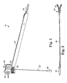
- Figure 1 is a perspective view of one embodiment of the present invention
- Figure 2 is a reversed, bottom view of the embodiment of Figure 1 , showing an implant assembly tool in an open position;
- Figure 3 is a bottom view of the embodiment of Figure 2 ;
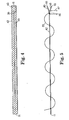
- Figure 4 is a top view of a segment of implantable material according to another aspect of the present invention.
- Figure 5 is a side view of Fig. 4 ;
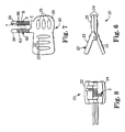
- Figure 6 is a side view of an implant assembly tool
- Figure 7 is a top view of the implant assembly tool of Figure 6 ;
- Figure 8 is an end view of the implant assembly tool of Figure 6 ;
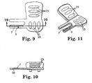
- Figure 9 is a bottom view of a component of the implant assembly tool of Figure 6 ;
- Figure 10 is a sectional view taken approximately along lines 10-10 of Figure 9 ;
- Figure 11 is a perspective view of the component of Figure 9 ;
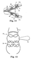
- Figure 12 is a side view of a portion of an implantable material within a portion of an implant assembly tool showing jaws of the implant assembly tool in an open position;
- Figure 13 is a plan view of a tab and portions of a loosening loop, showing knots being tied in the loosening loop on both sides of the tab;
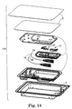
- Figure 14 is an exploded perspective view of a sterile kit according to an aspect of the present invention.
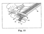
- Figure 15 is a schematic view of an implant assembly tool and synthetic implant material in an open position
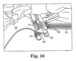
- Figure 16 is a schematic view of the implant assembly tool and implant of Figure 15 and a biological material inserted between portions of the synthetic implant material;
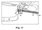
- Figure 17 is a schematic view of the components of Figure 16 after the implant assembly tool is released and allowed to move from the open toward its closed position;
- Figure 18 is a schematic view showing a suture being threaded through the synthetic and biological materials by passing a needle through a channel in the implant assembly tool with the needle being grasped by a surgical clamp;
- Figure 19 is a schematic view showing a suture being threaded through the synthetic and biological materials by passing a needle through a channel in the implant assembly tool similar to Figure 18 but just prior to the needle being grasped by a surgical clamp;
- Figure 20 is a schematic view showing a suture after it is passed through the implant and just prior to being tied;
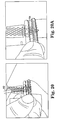
- Figure 20A shows the suture of Figure 20 just after it is tied
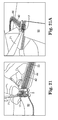
- Figure 21 is a schematic view of a blade being drawing along a slot in the implant assembly tool to cut a suture that holds the implant assembly tool to the synthetic implant material;
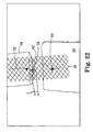
- Figure 22 is a schematic view showing a biomaterial sutured to a synthetic material after the implant assembly tool has been removed.
- Figure 23 shows a loosening loop being pulled to loosen the tension of an implanted sling.
- the present invention is directed to an assembly according to claim 1.
- Figures 1 through 14 show components of an assembly 100 for constructing a composite implant (e.g. a sling) for treating incontinence, particularly SUI.
- the composite implant comprises a first material and a second material that is different from the first material.
- the first material comprises a synthetic material (e.g. 42) and the second material comprises a biomaterial (e.g. 50 in Fig. 22 ) or non-synthetic material.
- one material comprises an absorbable material and the other material comprises a non-absorbable or permanent material.
- the one portion may be resorbable or absorbable, another portion may be non-absorbable and another portion may be constructed of a different material.
- a naturally occurring biomaterial may be used or a tissue engineered material may be used.
- tissue engineered material may be used.
- the materials substantially differ in a feature that can potentially affect a surgical procedure for treating a urological disorder, including the results.
- Features that can be different according to the present invention include, but are not limited to the ability of the sling to avoid infections or tissue (urethral) erosion (actual or perceived), the shelf life of the material, the type of material, the shape of the material, the presence of a sling tensioning member (e.g. as disclosed in published PCT Appl. No. WO/02/28315-A2 ), the present of a sling adjustment feature as described in published U.S. Pat.
- Suitable non-synthetic materials include allografts, homografts, heterografts, autologous tissues, cadaveric fascia, autodermal grafts, dermal collagen grafts, autofascial heterografts, whole skin grafts, porcine dermal collagen, lyophilized aortic homografts, preserved dural homografts, bovine pericardium and fascia lata.
- Suitable synthetic materials for a sling include polymerics, metals (e.g. silver filigree, tantalum gauze mesh, and stainless steel mesh) and plastics and any combination of such materials.
- non-absorbable materials include MarlexTM (polypropylene) available from Bard of Covington, RI, ProleneTM (polypropylene) and Mersilene (polyethylene terphthalate) Hernia Mesh available from Ethicon, of New Jersey, Gore-TexTM (expanded polytetrafluoroethylene) available from W. L. Gore and associates, Phoenix, Az., and the polypropylene sling available in the SPARCTM sling system, available from American Medical Systems, Inc. of Minnetonka, Minnesota.
- absorbable materials include DexonTM (polyglycolic acid) available from Davis and Geck of Danbury, CT, and VicrylTM available from Ethicon.
- suitable materials include those disclosed in published U.S. Pat. Application No. 2002/0072694 . More specific examples of synthetic sling materials include, but are not limited to polypropylene, cellulose, polyvinyl, silicone, polytetrafluoroethylene, polygalactin, Silastic, carbon-fiber, polyethylene, nylon, polyester (e.g. Dacron) PLLA and PGA.
- the synthetic portions may be knitted, woven, sprayed or punched from a blank. Some slings may be sufficiently robust to be inserted without a protective sleeve. In other embodiments, some synthetic slings may have an associated sheath or sleeve 44 (described in greater detail below).
- a synthetic portion may comprise a mesh material.
- the mesh material comprises one or more woven, knitted or inter-linked filaments or fibers that form multiple fiber junctions throughout the mesh.
- the fiber junctions may be formed via weaving, knitting, braiding, bonding, ultrasonic welding or other junction forming techniques, including combinations thereof.
- the size of the resultant openings or pores of the mesh may be sufficient to allow tissue in-growth and fixation within surrounding tissue.
- the holes may comprise polygonal shaped holes with diagonals of 0.132 inches and 0.076 inches.
- the quantity and type of fiber junctions, fiber weave, pattern, and material type influence various sling properties or characteristics.
- the mesh may be woven polypropylene monofilament, knitted with a warp tricot.
- the stitch count may be 27.5 courses/inch (+ or - 2 courses ) and 13 wales/inch (+ or - 2 wales).
- the thickness of this example is 0.024 inches.
- This embodiment of sling is preferably associated with a sleeve 44. Non-mesh sling configurations are also included within the scope of the invention.
- the mesh 42 is preferably elastic, as opposed to the substantially inelastic mesh available in Europe as Uratape® from Porges, and the tape described in Published U.S. Pat. Appl. No. 2002/0099260 .
- a test for defining whether a synthetic material is elastic is disclosed in U.S. Patent Application No. 10/306,179 filed November 27, 2002 .
- a sheath 44 is preferred when the sling 42 is elastic. After the sling is implanted, the sheath 44 is removed and discarded.
- the sheath 44 is constructed of a material that affords visual examination of the implantable sling material 42 and that affords convenient passage through tissue of the patient.
- the sheath 44 is made of polyethylene. Other materials including, without limitation, polypropylene, nylon, polyester or Teflon may also be used to construct the sheath 44.
- the sheath 44 should also conveniently separate from the sling material 42 after the sling 42 is implanted without materially changing the position of the sling 42.
- a portion of the sling material 42 projects from an end of the sheath 44.
- the length of this projection may comprise, for example, about an inch.
- the sheath 44 may comprise an extendable member that can be movable from i) a retracted position with a portion of the sling material projecting from an end of the sheath 44 to afford joining of the leg portions 43 and 44 to a biomaterial 50 ( Fig. 22 ), to ii) an extended position with additional or all of the material of component 42 covered thereby. It is believed that extending the sheath over additional parts of the material of component 42 (e.g. seam 35) may afford a smoother transition at this position.
- An extendable sheath may be accomplished in a variety of fashions including Z-folding the sheath, constructing the sheath of a stretchable or expandable material, and the like.
- the mid-portion of the assembled sling (the portion designed to reside underneath the urethra, preferably the mid urethra) is preferably substantially free of any silicone coatings. Alternative placements for the mid-portion are also contemplated herein, such as at the bladder neck or elsewhere. A variety of factors can influence the surgeon's decision, such as the presence or absence of scarring, the condition of the urethral tissue and other factors.
- the sling material components may have one or more substances associated therewith through a process such as coating or they may be incorporated into the raw material of the sling.
- appropriate substances include, without limitation, drugs, hormones, antibiotics, antimicrobial substances, dyes, silicone elastomers, polyurethanes, radiopaque filaments or substances, anti-bacterial substances, chemicals or agents, including any combinations thereof.
- the substances may be used to enhance treatment effects, reduce potential sling rejection by the body, reduce the chances of tissue erosion, enhance visualization, indicate proper sling orientation, resist infection or other effects.
- the assembled slings are preferably substantially polygonal for treating SUI in females, other shapes are also contemplated. Depending on the treatment addressed (e.g. to provide hammock support for the bladder or bladder neck, or to address a rectocele, enterocele or prolapse) the slings may be any of a wide variety of shapes.
- Components 42 are preferably rectangular.
- Suitable synthetic, non-synthetic, absorbable and non-absorbable biocompatible implant materials are disclosed in the conference proceedings of Julian, TM, Vaginal Reconstruction Using Graft Materials, 12th International Pelvic Reconstructive and Vaginal Surgery Conference, St. Louis, Mo., Sept. 25-28, 2002 .
- a non-synthetic material may be constructed according to the teachings of U.S. Provisional Patent Appl. No. 60/405,139, filed August 22, 2002 .
- Other suitable materials for forming portions of the composite sling are described in published U.S. Pat. No. 2002-0138025-A1, published September 26, 2002 .
- Figures 4 and 5 show a first material or segment 42 (preferably a synthetic mesh) suitable for forming a first portion of the implant.
- Assembly 100 ( Fig. 14 ) includes sub assembly 10.
- Subassembly 10 includes a first segment comprising first material 42 (e.g. a synthetic material) with a distal end 11 and an attachment or integration end 15.
- the subassembly 10 also optionally includes sheath 44 and implant assembly tool 20.
- the first material 42 may be provided as part of a subassembly 10 which is described in greater detail below.
- the assembly 100 preferably includes a second subassembly 10.
- the segment 42 optionally has a tensioning filament or suture 33.
- Tensioning filaments are generally disclosed in U.S. Published Pat. Application No US-2002-0107430-A1 .
- the particular tensioning suture 33 may be constructed from a permanent or absorbable material and is described in greater detail below.
- the present invention also includes an integrator for associating a second type of material (e.g. a biomaterial) with the attachment ends 15 of first and second segments of material 42 so that the biomaterial may be placed underneath the patient's urethra.
- a second type of material e.g. a biomaterial
- the integrator includes Y-shaped portion having leg portions 43 and 45 at the attachment end of segment 42.
- the leg portions 43 and 45 may be constructed in any suitable manner, such as creating a seam 35.
- the seam 35 may be created in any suitable fashion such as by suturing a piece of biocompatible material suitable for forming a leg 43 or 45 to the rest of the component 42, welding such a piece or adhering such a piece.
- the length of the legs 43 and 45 is preferably sufficient to afford convenient attachment to biomaterial (e.g. 50 Fig. 22 ). For example, the length may be between 0.25 and 1 inch, preferably about 0.5 inches.
- the width and thickness of the leg portions 43 and 45 is preferably similar to those of the rest of the component 42.
- the surgeon may join the biomaterial (e.g. 50 in Fig. 22 ) to the segment 42 by suturing them together at the Y-shaped portion.
- one of the legs 43 or 45 may be of a material that is different than the rest of the component 42 and the biomaterial 50 to perform as a bridge between material 42 and material 50.
- the segments 42 are sized and shaped to extend from a position substantially adjacent the patient's urethra to a position substantially adjacent the patient's rectus fascia so that the first and second segments and the biomaterial can provide a U-shaped sling extending from the patient's rectus fascia in the abdominal region, to a position below the patient's urethra, and back to the rectus fascia on an opposite side of the patient's urethra.
- the sheath length of the assembly is approximately within the range of 24 cm to 30 cm
- sheath width is approximately within the range of 1.0 cm to 2 cm
- sheath material thickness is approximately within the range of 0.127 mm to 0.203 mm, respectively.
- the associated sling mesh 42 has a length, width and thickness approximately within the range of 22 cm to 24 cm; 1.0 cm to 2 cm; and 0.508 mm to 0.711 mm, respectively.
- a sheath is preferably connected to the mesh (e.g. by an ultrasonic weld or other suitable attachment method) adjacent an end of the mesh.
- the overall dimensions of the assembly including sheath 44 and sling 42 may be selected for a transobturator type surgical procedure.
- the sheath and sling should be sufficient, when combined with a biomaterial for the mid portion, to extend from a superficial incision near the obturator fascia, to an undersurface of the urethra and then to another incision adjacent obturator fascia that is opposite the first incision.
- the skin incisions need not be made and the ends of the sling can rest underneath the skin.
- the size of the sling can take into account the imprecision associated with the range of human anatomy sizes.
- the sheath length of the assembly is approximately within the range of 18 cm to 24 cm
- sheath width is approximately within the range of 1.0 cm to 2 cm
- sheath material thickness is approximately within the range of 0.127 mm to 0.203 mm, respectively.
- the associated sling mesh has a length, width and thickness approximately within the range of 15 cm to 17 cm; 1.0 cm to 2 cm; and 0.508 mm to 0.711 mm, respectively.
- the assembled sling and/or components thereof may be designed for placement through the retropubic space of the patient without abdominal incisions.
- Such procedures are disclosed in U.S. Pat. No. 6,382,214 , and published U.S. Pat. Application Nos. 2002/0161382 A1 and 2002/0128670 A1 .
- the segment 42 preferably includes a tensioning filament 33 for adjusting placement of the sling within the patient.
- the undulations of the tensioning filament 33 are exaggerated to show that it alternates between a first and a second major surface of the segment 42.
- filament 33 is preferably taught.
- the tensioning filaments 33 are preferably fixed at each end (e.g. 33') to the sling material (e.g. a polypropylene mesh) by welding (e.g. ultrasonic), knotting, anchoring, adhering (e.g. with and adhesive) or the like. They may comprise absorbable or non-absorbable sutures.
- the tensioning filament 33 is preferably attached to the synthetic material 42 at a location 33' substantially adjacent, yet spaced from legs 43 and 45 of the Y-shaped portions.
- the segments 42 optionally include a removable loosening loop 47 operatively associated with tensioning filament 33.
- the removable loosening loop 47 is adapted to be cut (e.g. with cutting instrument 57, see Fig. 23 ) and removed once the implant is properly tensioned.
- the assembly may optionally include a convenient tab 49 associated with the loosening loop.
- the tab 49 may be constructed from a biocompatible material such as silicone.
- the tab 49 may be sized and shaped to receive a hemostat clamped thereto for the convenience of the surgeon.
- the loosening loop 47 preferably includes a pair of knots 76 and 78.
- the knots 76 and 78 are provided so that when the loosening loop 47 is cut (e.g. see Fig. 23 ), the loosening loop 47 may be removed from the synthetic segment 42 without a knot 76 or 78 and/or tab 49 passing through the segment 42.
- the loosening loop 47 is looped around seam 35 of the Y-shaped portion to resist damage to biomaterial 50 and/or the attachment between the biomaterial 50 and the synthetic material 42 during adjustment of the placement of the sling within the patient, and or the attachment 33' of tensioning filament 33.
- knot 76 may comprise single throw overhand knots and knot 78 may comprise double throw overhand knots.
- the subassemblies 10 may optionally includes sheath 44, a dilator 54 and an implant assembly tool 20 depending upon a variety of factors such as the specific needle used to insert the sling, the specific sling material(s), the presence or absence of concomitant procedures, the specific sling procedure contemplated, the configuration of the sling components (e.g. whether they include a Y-shaped end) and the specific integrator used.
- Figures 1 through 3 show a novel implant assembly tool 20 for association with the synthetic material 42 for holding the synthetic material 42 while a different implant material is attached to the integration end 15.
- Assembly 100 may include a dilator 54 ( Fig. 2 ) for use in a surgical sling procedure.
- the dilator is optional but present in some preferred embodiments.
- the dilator 54 comprises surfaces for associating the dilator with a needle (e.g. end 58 of needle 16).
- the kit shown in Figure 14 includes two dilators 54.
- the dilators 54 atraumatically create and/or expand the passageway through the tissues for sling assembly delivery.
- the tip or leading end of the dilator 54 is preferably blunt, as, in preferred embodiments, the leading tip of the dilator 54 will pass through tissue that has already been pierced by a needle 16.
- the dilator 54 may be made from a variety of biocompatible and sterilizable materials including, without limitation, acetal, polycarbonate, polypropylene, Delrin®, Acrylonitrile-ButadieneStyrene (ABS), polyethylene, nylon and any combination of biocompatible materials.
- the dilator 54 preferably includes means for associating with a surgical needle 16.
- the association means affords a permanent affixation between the dilator 54 and the needle 60.
- permanent affixation it is meant that it would be very difficult to manually separate the dilator from the needle after they have become permanently affixed.
- the association means preferably affords quick and convenient attachment of the dilator 54 to the needle 16 to avoid wasting time in the midst of a surgical procedure. The attachment should also be secure to avoid separation of the needle 16 and dilator 54 while the combination is passed through tissue.
- the assembly tool 20 comprises holders for retaining the first and second biocompatible materials in a substantially flat condition while the first 42 and second 50 biocompatible materials are attached, and a passageway 5 ( Fig. 12 ) for passage of a joiner for attaching the first material 42 to the second material 59.
- the joiner may comprise a needle/suture combination 99 chosen by the surgeon or it may comprise another joining element such as a staple, grommet, screw, mechanical fastener, biocompatible adhesive, pledget, or anchor.
- the holders preferably comprise a pair of jaws 60.
- the first biocompatible material 42 preferably comprises a Y-shaped structure described above.
- each jaw 60 is associated with a leg portion 43 or 45 of the Y-shaped structure ( Fig. 12 ).
- the jaws 60 are movable between an open position ( Fig. 12 ) with the leg portions spaced apart to receive the second biocompatible material therebetween, and a closed position (e.g. Fig's. 17 and 18) with the leg portions 43 and 45 spaced closer together than in the open position.
- Seam 35 has axis A ( Fig. 4 ) that is perpendicular to the longitudinal axis A' of the sling.
- the jaws 60 are mounted to pivot about an axis J ( Fig. 7 ) that is substantially parallel or colinear with the axis A of the seam 35 so that ends 15 of the leg portions 43 and 45 remain substantially parallel during movement between the open and closed positions. This contributes to a desired non-wrinkled joining of components 42 and 50.
- the passageway 5 of the assembly tool 20 preferably comprises an open ended channel formed by tines 26 and 28.
- the channel is sized and shaped to afford passage of a suture and needle combination 99.
- the channel is preferably sufficiently large to afford a wide variety of suture and needle combinations.
- the channel can have a width of more than about 0.1 inches and less than about 0.7 inches, more preferably about 0.15 inches, and a length of more than about 0.2 and less than about 1.5 inches, more preferably about 0.65 inches.
- the passageway may comprise a hole or other void such as those shown and described in U.S. Provisional Application Serial No. 60/405,139, filed August 22, 2002 .
- the jaws 60 are preferably associated with the legs 43 and 45 of the synthetic material 42 by a suture 17, 17A that connects a tine 28 to a leg portion 43 or 45. This may preferably be accomplished with a through hole 9 in tine 28.
- the implant assembly tool 20 may be associated with the synthetic material by interaction between a structured surface on the inner surface of jaws 60 and the synthetic material 43 or 45.
- the structured surface may comprise hooks for a hook and loop type association between the implant assembly tool and the synthetic material.
- hook and loop type fasteners are believed suitable for use in the present invention, such as the fasteners described in U.S. Pat. Nos. 3,359,980 to Rosenblatt , 3,694,867 to Stumpf , 3,913,183 to Brumlik , 4,609,581 to Ott , 4,739,635 to Conley et al. , 4,761,318 to Ott et al. and 4,770,917 to Tochacek et al .
- tine 28 of each jaw 60 includes a cutting slot 7 adapted to receive a blade 71 ( Fig. 21 ) to guide the blade 71 as it cuts the suture 17 that associates the tine 28 with a leg portion 43 or 45 to separate the implant assembly tool 20 from the synthetic material 42 once the synthetic material 42 is attached to the biomaterial 50.
- Indicia 69 is preferably provided to assist the surgeon in visualizing the slot 7. For example, if the material of the tool is a substantially light color, the indicia 69 may be dark.
- the suture that associates the tine with a leg portion includes a pair of knots and/or loops 17 and 17A so that when the suture 17 is cut, the suture remains with the implant assembly tool 20 by virtue of loop or knot 17A. This helps ensure that a portion of suture 17 or 17A is not inadvertently left with the material 42.
- the jaws 60 include indicia 63 for indicating preferred location of suture passage for attaching the synthetic material 42 to the biomaterial 50.
- the indicia 63 may comprise bar defining an imaginary area B for preferred passage of the needle/ suture combination 99.
- the indicia 63 may also cooperate with indicia 69 to assist the surgeon in visualizing channel 5.
- the jaws 60 preferably include manually engageable portions 29 ( Fig. 7 ) for grasping the assembly tool 20 while the suture and needle combination 99 (See Fig.'s 18-20) is passed through the channel 5. This can contribute to the aseptic nature of the composite sling assembly as the surgeon need not touch either biomaterial 50 or either leg 43 or 45.
- assembly tool 20 also preferably includes biasing means (e.g. a coil spring 2) for biasing the jaws toward the closed position, and opening flanges 22 for pressing on to move the jaws 60 from the closed toward the open position against the bias of the spring 2.
- biasing means e.g. a coil spring 2
- opening flanges 22 for pressing on to move the jaws 60 from the closed toward the open position against the bias of the spring 2.
- Alternative, embodiments of the biasing means are within the scope of the present invention, such as leaf springs, integral springs and the like.
- the implant assembly tool 20 includes handle portions 22 and 24 with structure e.g. raised ribs 23 for enhancing manual grasping of the implant assembly tool 20.
- Jaws 60 may also include similar structures 25 on surface 29 to assist in holding the tool 20 during suturing of the materials 42 and 50.
- Suitable materials are biocompatible and include metals and plastics. Examples of metals include titanium and stainless steels.
- Suitable polymerics include nylons (e.g. 30% glass filled Nylon), polyethylene, polypropylene and Teflon (e.g. polytetrafluoroethylene), and combinations thereof.
- a surgical kit 100 according to the present invention may optionally include additional accessories.
- a surgical drape specifically designed for urological procedures such as a sling procedure may be included in a kit of the present invention.
- a drape is disclosed in published U.S. Pat. Appl. No. 2002-078964-A1 .
- an article for objectively setting tension of the sling such as one of the articles described in PCT Publication No. PCT WO/02 / 28315-A1 may be included in the kit.
- kits 100 optionally include at least two needles.
- the needles may comprise the needles disclosed in published U.S. Pat. Application No. 2003/0065246-A1 , and/or the needles described in published U.S. Pat. Application Nos. 2002-0151762-A1 ; 2002-0147382-A1 ; 2002-0107430-A1 , US-2002-0099258-A1 and US-2002-0099259-A1 ; and U.S. Provisional Application Serial Nos.
- the needles comprise needles as described in U.S. Patent Application No. 10/306,179 filed November 27, 2002 .
- the needles may be substantially identical, in other instances, they may be different. Two or more needles reduce the need to reuse a non-sterile needle at a different location with a patient, thereby eliminating cross contamination issues. Additional needles, handles, dilators and other elements may also be included for surgical convenience, for avoidance of contamination from one portion of the body to another, for ease of manufacturing or sterilization or for surgical requirements.
- a composite sling assembly may be assembled by the surgeon or provided preassembled using the teachings or components of published U.S. Pat. Application Nos. 2002-0147382-A1 or 2002-0082619-A1 .
- the individual elements of the kits of the present invention may be packaged together as shown in Fig. 14 , separately or in subassemblies depending on a variety of factors such as shelf life and sterilization requirements. They may be assembled at the manufacturing location or at the healthcare location. Any suitable sterilization procedure may be utilized to sterilize the contents of a kit. Suitable sterilization techniques include, but are not limited to steam, ethylene oxide, electron beam, vapor (e.g. hydrogen peroxide or peracetic acid), gamma or plasma procedures.
- the needles 16 may be reusable or single use devices.
- Figure 14 illustrates an embodiment with a composite sling assembly may be assembled by the surgeon or provided preassembled using the teachings or components of published U.S. Pat. Application Nos. 2002-0147382-A1 or 2002-0082619-A1 .
- the individual elements of the kits of the present invention may be packaged together as shown in Fig. 14 , separately or in subassemblies depending on a variety of factors such as shelf life and sterilization requirements. They may be assembled at the manufacturing location or at the healthcare location. Any suitable sterilization procedure may be utilized to sterilize the contents of a kit. Suitable sterilization techniques include, but are not limited to steam, ethylene oxide, electron beam, vapor (e.g.
- the needles 16 may be reusable or single use devices.
- Figure 14 illustrates an embodiment with two needles 16 and two subassemblies 10 (e.g. see Fig. 1 ) with typical packaging such as a tray T, inserts I and covers C. These components may have relatively similar shelf lives (as opposed to some biomaterials) and are thus preferably packaged together.
- a biomaterial (e.g. cadaveric fascia) 50 for forming a mid-portion of a sling would preferably be packaged separately as it is likely to have a substantially different shelf life.
- the above-described surgical instruments may be disposable or reusable.
- portions of the surgical instrument may be reusable (sterilizable) and other components may be disposable.
- the present invention is particularly suitable for placing a sling in a therapeutically effective position.
- the method may be utilized to support a variety of structures at different anatomical locations. Variations of these methods may occur due to individual surgeon's techniques or a patient's particular anatomy.
- FIG. 15 through 23 there is shown a method for assembling a composite sling for use in a sling procedure similar to that provided in the instructions for use in the SPARC Sling System, available from American Medical Systems of Minnetonka, Minnesota.
- the present invention may be utilized in alternative surgical approaches and anchoring methods such as those described in the instructions for use for the TVT procedure, the In-Fast Ultra surgical procedure available from American Medical Systems of Minnetonka, Minnesota, and the procedures described in U.S. Pat. Nos. 5,899,909 ; 6,406,480 , published U.S. Pat. Application Nos. 2002/0188169 A1 and 2002/0022841 A1 , and U.S. Patent Application Nos. 10/106,086, filed March 25, 2002 , and 10/306,179 filed November 27, 2002 .
- the present invention may comprise a surgical method for treating incontinence, comprising the steps of: (1) providing a first sling segment comprising a synthetic material having a distal end and an attachment end; and a second sling segment comprising a synthetic material having a distal end and an attachment end; (2) integrating a biomaterial with the attachment ends of the first and second segments so that the biomaterial may be placed underneath the patient's urethra, and (3) then implanting the first and second segments and the integrated biomaterial so that they provide a sling extending from a position substantially adjacent the patient's obturator foramen in the pelvic region, to a position below the patient's urethra, and then to the patient's obturator foramen on an opposite side of the patient's urethra.
- the surgeon selects and prepares (if required) the desired graft or biologic material 50.
- the graft material may comprise InteXen, InteDerm or InteLata graft materials available from American Medical Systems, of Minnetonka, Minnesota. Some graft materials may be folded to increase attachment strength to the Y- shaped portion of the mesh. Some examples may be found in the table below: Type Attachment Recommendation InteXen No Fold InteDerm No Fold InteLata Folded Ends Autologus Folded Ends
- handles 22 and 24 are squeezed to open the tool 20.
- the surgeon's choice of graft material is aseptically inserted into the Y-mesh, preferably using printed marks 63 ( Fig. 7 ) on the tool 20 as guides to center the graft.
- the surgeon releases handles 22 and 24 to close the tool 20 to secure the graft material between the legs 43 and 45 of the Y-shaped portion.
- a suture is passed up using a suture/needle combination 99.
- a clamp 61 e.g. a hemostat
- Figure 19 shows the needle 99 prior to being grasped by the clamp 61.
- the suture mark 63 may be used as a guide for passage of the suture.
- the sutures are passed in the area defined by imaginary box B shown in Fig. 7 .
- the sutures are preferably passed so that the attachment knots are on an optional printed side of the sheath 44 in order, for example, to control the final orientation of the knots relative to the urethra.
- the suture is then passed down using the opposite suturing mark (see 63) as a guide.
- the passed suture 99 is then secured using a knot 64 of the surgeon's choice (e.g. a surgeon's knot).
- a knot 64 of the surgeon's choice e.g. a surgeon's knot.
- Suitable knots for use in this and other embodiments of the present invention are described in the ETHICON Knot Tying Manual ( ⁇ 1999-2000), available from ETHICON, of NJ. Additional knots and/or throws may be accomplished if desired or needed. For example, when using InteLata from American Medical Systems (Human Fascia Lata), two suture throws may be preferred.
- a blade 71 e.g. knife, scalpel or scissors
- a blade 71 is then utilized to cut assembly tool sutures 17 by passing the blade 71 down groove 7 in each jaw 60 of the tool 20.
- a suture is cut on each side of the mesh 42.
- the direction of cutting is away from the surgeon.
- Optional printing 69 helps indicate the location of the groove 7.
- the implant assembly tool 20 may then be removed from the assembled implant 42/50.
- the tool sutures 17 remain with the assembly tool 20 due to the second knot 17A (see Fig. 12 ).
- a catheter e.g. Foley
- a catheter e.g. Foley
- Two small transverse suprapubic abdominal stab incisions may be made near the back of the pubic bone (e.g. each about 1 cm from the midline, or alternatively, one large incision may be made) to allow for needle entry.
- a small incision e.g. a transverse incision
- a small incision is made in the anterior vaginal wall followed by a transurethral dissection. For example, a 1.5 cm vertical incision on the anterior vaginal wall starting approximately 1.0 cm from the urethral meatus may be performed.
- Two small paraurethral dissections may be made to allow the surgeon finger to meet blunt distal end 58 of needle 16. The amount of dissection may vary according to surgeon preference.
- Needles 16 may be inserted by initially passing distal ends 58 through abdominal incisions and then through a vaginal incision.
- the dilators 54 may then be connected to the distal end 58 of the needle emerging from the vaginal incision.
- the printed side of the sheath is placed away from the urethra, facing the surgeon.
- One dilator 54 is attached to each of the needles on the ends 58. The surgeon then inspects the assembly to ensure that the sling is substantially flat (not canoe shaped or twisted prior to attaching the second dilator 54 to the second needle 16).
- the needles 16 are securely attached to the dilators 54, the needles 16 are pulled up through the suprapubic (abdominal) incision(s).
- the surgeon ensures that the biologic material of choice is generally flat under the urethra, which may facilitate healing in the immediate postoperative period. This may be accomplished by the method preferred by the physician; such as trimming, providing lateral dissection to allow the material to lay flat against the urethra, or suturing the biologic of choice on either side of the urethra (e.g. at four points).
- Each end of the sling mesh projecting from the abdominal incision(s) may be secured with a hemostat or a clamp.
- the sling mesh may be cut approximately 3 cm away from the dilating connectors 54, assuring that the surgeon has cut below the optional markings at each end of the sheath 44.
- the sling is preferably positioned under the midurethra without tension.
- the biological material 50 is centered under the urethra keeping suture knots away from the urethra prior to removing the sheaths 44.
- the surgeon removes the sheath 44 from the sling mesh 42 by pulling up from both sides, preferably one side at a time.
- a surgeon may keep a forceps or other instrument between the graft material 50 and urethra during removal.
- the tensioning suture 33 in the sling mesh may be used for further tensioning adjustment once the sheath 44 is removed.
- the tensioning suture 33 allows for adjustment of the sling mesh in the immediate post-operative period.
- the surgeon may place a device such as a clamp, across the mesh 42, suprapubically.
- a device such as a clamp
- the surgeon ensures that both the tensioning suture 33 and the complete width of the sling mesh 42 are captured within the clamp.
- the sling mesh may then be rolled around the clamp to improve the grip.
- the surgeon pulls up to tighten the sling mesh as desired. If needed, this can be repeated on the contralateral side.
- the surgeon may use a hemostat or a clamp 49 to pull from one or more of the hanging loosening loops 47 (only one is shown in Fig. 23 ).
- the clamp 49 is used to pull down and loosen the composite sling as desired.
- the loosening loops 47 are then cut (e.g. with scissors 57) and tab 49 may be pulled on to release loop 47. Because the loop 47 includes two knots 76, 78 ( Fig. 13 ), the loop 47 may be released without passing a knot through the mesh 42.
- the precise, final location of the composite sling will depend on a variety of factors including the particular surgical procedure(s) performed, and any preconditions of the patient such as scar tissue or previous surgeries. For example, it may be preferred to place the portion 50 of the sling in close proximity to, but not in contact with, a mid portion of the urethra to treat incontinence. Alternatively, the sling may be placed near the bladder neck.
- the distal ends of the sling mesh 42 are again trimmed to size at the suprapubic incisions, and the suprapubic and vaginal incisions are closed.
- a Foley catheter or suprapubic tube can be utilized until the patient is able to void.
Abstract
Description
- Urinary incontinence is a significant health concern worldwide. Millions of people worldwide suffer from this problem. There are many different forms of incontinence. One of the most common is known as stress urinary incontinence (hereafter SUI).
- A pubovaginal sling procedure is a surgical method involving the placement of a sling to stabilize or support the bladder neck or urethra. There are a variety of different sling procedures. Descriptions of different sling procedures are disclosed in
U.S. Pat. Nos. 5,112,344 ;5,611,515 ;5,842,478 ;5,860,425 ;5,899,909 ;6,039,686 ;6,042,534 and6,110,101 . - Slings for treating incontinence may be constructed from synthetic materials such as polypropylene, polytetrafluoroethylene, polyester and silicone. Slings constructed from non-synthetic materials include allografts, homografts, heterografts, autologous tissues, cadaveric fascia and fascia lata. The strength and other properties of certain non-synthetic sling materials have been reported in the literature. See, Chaikin et al., Weakened Cadaveric Fascial Sling: An Unexpected Cause of Failure, Journal of Urology, Vol. 160, 2151 (Dec. 1998); Choe et al., Autologous, Cadaveric, and Synthetic Materials Used in Sling Surgery: Comparative Biomechanical Analysis; Urology 58 (3), Pps. 482-86; 2001; and Lemer et al., Tissue Strength Analysis of Autologous and Cadaveric Allografts of the Pubovaginal Sling, Neurology and Urodynamics 18:497-503 (1999). While some non-synthetic sling materials are generally preferred by surgeons and patients, the quality of some non-synthetic materials (e.g. cadaveric sling material) varies greatly.
- The supply of non-synthetic materials for slings varies greatly. Certain sizes of non-synthetic materials can be especially difficult to secure in a timely fashion. For example, autologous material may be difficult or impossible to harvest from some patients due to a variety of factors, including the health of the patient and the size of the tissue needed for a sling.
- Some surgeons prefer synthetic materials, as they are readily available. The influence of various sling materials on tissue has been investigated. See Ulmsten et al., Intravaginal Slingplasty (IVS): An Ambulatory Surgical Procedure For Treatment of Female Urinary Incontinence, Scand. J. Urol. Nephrol 29: 75-82 (1995); Falconer et al., Influence of Different Sling Materials on Connective Tissue Metabolism in Stress Urinary Incontinent Women, Int. Urogynecol. J. (2001) (Suppl. 2): S19-S23; and Bent et al., Tissue Reaction to Expanded Polytetrafluoroethylene Suburethral Sling for Urinary Incontinence: Clinical and Histological Study, Am. J. Obstet. Gynecol., Vol 169, No. 5 Pps. 1198-1204 (1993).
- Other relative advantages and disadvantages exist between non-synthetic and synthetic sling materials.
- Some surgical procedures for incontinence utilize autologous tissue to provide a sling. See Aldridge, Transplantation of Fascia for Relief of Urinary Stress Incontinence, Am. J. of Obstetrics and Gynecology, v. 44, pages 398-411 (1948). There are significant recovery and morbidity issues associated with harvesting the sling material from the patient. See Sloane et al., Stress Incontinence of Urine: A Retrospective Study of the Complications and Late Results of Simple Suprapubic Suburethral Fascial Slings, J. of Urology, vol. 110, Pps. 533-536 (1973).
- Some pubovaginal sling procedures extend a sling from the rectus fascia in the abdominal region, to a position below the urethra, and back again to the rectus fascia. Some slings are anchored in the abdominal fascia by virtue of suturing the sling material to the patient' abdominal tissue (e.g. rectus fascia). See Blaivas, Commentary: Pubovaginal Sling Procedure, Current Operative Urology, Edited by E.D. Whitehead, Philadelphia: J.B. Lippincott Co. Pp. 93-100 (1990) (biologic sling); and Moir, The Gauze-Hammock Operation, The Journal of Obstetrics and Gynaecology of the British Commonwealth, Vol. 75, No. 1, Pps. 1-9 (1968) (synthetic implant). Although serious complications associated with sling procedures are infrequent, they do occur. Complications include urethral obstruction, prolonged urinary retention, bladder perforations, damage to surrounding tissue, and sling erosion.
- The Tension-free Vaginal Tape (TVT) procedure (available from Ethicon, of N.J.) utilizes a Prolene™ nonabsorbable, polypropylene mesh. The TVT mesh extends from the rectus fascia in the abdominal region, to a position below the urethra, and back again to the rectus fascia. No suture is recommended to tie the end of the mesh to the rectus fascia. Problems with the TVT procedure are documented in the literature and patents. See PCT publication nos.
PCT WO 00/74613 PCT WO 00/74594 U.S. Pat. Nos. 6,273,852 ;6,406,423 ; and6,478,727 , and publishedU.S. Pat. Application Nos. 2002-0091373-A1 ,2002-0107430-A1 ,2002-0099258-A1 andUS-2002-0099259-A1 . See also, Walters, Mark D., Percutaneous Suburethral Slings: State of the Art, presented at the conference of the American Urogynecologic Society, Chicago (October 2001) andPCT International Publication No. WO 02/26108 - Additional sling procedures are disclosed in Published U.S. Pat. Appl. No.
US 2001/0018549A1 , andPCT Publication Nos. WO 02/39890 WO 02/069781 -
PCT Published Application No. WO 00/74633 - Published
U.S. Pat. Appl. No. 2002/0099260 discloses an implantable device or tape for use in correcting urinary incontinence. The tape includes sprayed polypropylene fibers that result in a strong implantable device. The tape also has a silicone-coated portion and tapered free ends. -
U.S. Pat. No. 6,306,079 discloses a mesh pubovaginal sling comprising two pieces. One piece comprises a polypropylene mesh and a second mesh portion comprises an absorbable material such as poly-dioxanone. One piece may be inserted at the endopelvic fascia and the other in the suprapubic region. The two pieces are then connected via suture to support prolapsed organs so as to relieve urinary stress incontinence. -
U.S. Pat. No. 6,355,065 discloses an implantable support that may be used in suburethral stabilization procedures for reducing stress incontinence. Ends of the support are folded to reinforce suture holes and to inhibit fraying or rupturing. Threading mechanisms may be provided to facilitate threading of sutures through suture holes. A removable, elongated clip may be placed on an intermediate portion of the implant to inhibit folding of the implant about its longitudinal axis. This document speculates that longitudinal folding of the implant could cause dead space in which bacteria could collect. -
U.S. Pat No. 6,042,534 discloses a stabilization sling for use in minimally invasive pelvic surgery. The sling may include reinforced suture receiving sites. Ends of the sling may be folded over to reinforce the sling. -
PCT International Publication No. WO 02/28312 - Published
U.S. Pat Application No. 2002/0028980 discloses a Y-shaped implantable article for use in a sacral colpopexy procedure. PublishedU.S. Pat Application No. 2002/0082619 discloses a reinforcing fastener guide for enhancing the functional longevity of an implant such as a sling. -
WO 02/058564 A2 - a first segment comprising a synthetic material having a distal end and an attachment end;
- a second segment comprising a synthetic material having.a distal end and an attachment end;
- a biomaterial;
- an integrator for associating said biomaterial with the attachment ends of the first and second segments so that the biomaterial may be placed underneath the patient's urethra,
- wherein the first and second segments are sized and shaped to extend from a position substantially adjacent the patient's urethra to a position substantially adjacent the patient's rectus fascia so that the first and second segments and the biomaterial can provide a U-shaped sling extending from the patient's rectus fascia in the abdominal region, to a position below the patient's urethra, and back to the rectus fascia on an opposite side of the patient's urethra.
- SUMMARY OF THE INVENTION
- The present invention is defined by the features of the claims.
- The invention comprises an assembly of components for use in constructing a composite sling for treating a patient's incontinence. The assembly comprises a first segment comprising a synthetic material having a distal end and an attachment end; a second segment comprising a synthetic material having a distal end and an attachment end; a biomaterial ; and an integrator for associating the biomaterial with the attachment ends of the first and second segments so that the biomaterial may be placed underneath the patient's urethra. The first and second segments are specially sized and shaped. They may be sized and shaped to extend from a position substantially adjacent the patient's urethra to a position substantially adjacent the patient's rectus fascia so that the first and second segments and the biomaterial can provide a U-shaped sling extending from the patient's rectus fascia in the abdominal region, to a position below the patient's urethra, and back to the rectus fascia on an opposite side of the patient's urethra. Alternatively, they may be sized and shaped extend from a position substantially adjacent the patient's urethra to a position substantially adjacent the patient's obturator foramen so that the first and second segments and the biomaterial can provide a sling extending from a position substantially adjacent the patient's obturator foramen in the pelvic region, to a position below the patient's urethra, and to the patient's obturator foramen on an opposite side of the patient's urethra.
- The integrator comprises Y-shaped portions at the attachment ends of the first and second segments. The surgeon may join the biomaterial to the first and second segments by suturing them together.
- In a preferred embodiment, the first and second segments include a tensioning filament for adjusting placement of the sling within the patient. The tensioning filament is preferably attached to the synthetic material at a location substantially adjacent, yet spaced from legs of the Y-shaped portions. Also preferably, each of the first and second segments further include a removable loosening loop operatively associated with a tensioning filament. The removable loosening loop is adapted to be cut and removed once the implant is properly tensioned. The assembly may optionally include a convenient tab associated with the loosening loop. The loosening loop preferably includes a pair of knots so that when the loosening loop is cut, it may be removed from the synthetic segment (the sling) without a knot passing through the segment. Preferably, the loosening loop is looped around a seam of the Y-shaped portion to resist damage to a biomaterial of the sling and the attachment between the biomaterial and the synthetic material during adjustment of the placement of the sling within the patient
- Other features and advantages of the present invention will be seen as the following description of particular embodiments progresses in conjunction with the drawings, in which:
-
Figure 1 is a perspective view of one embodiment of the present invention; -
Figure 2 is a reversed, bottom view of the embodiment ofFigure 1 , showing an implant assembly tool in an open position; -
Figure 3 is a bottom view of the embodiment ofFigure 2 ; -
Figure 4 is a top view of a segment of implantable material according to another aspect of the present invention; -
Figure 5 is a side view ofFig. 4 ; -
Figure 6 is a side view of an implant assembly tool; -
Figure 7 is a top view of the implant assembly tool ofFigure 6 ; -
Figure 8 is an end view of the implant assembly tool ofFigure 6 ; -
Figure 9 is a bottom view of a component of the implant assembly tool ofFigure 6 ; -
Figure 10 is a sectional view taken approximately along lines 10-10 ofFigure 9 ; -
Figure 11 is a perspective view of the component ofFigure 9 ; -
Figure 12 is a side view of a portion of an implantable material within a portion of an implant assembly tool showing jaws of the implant assembly tool in an open position; -
Figure 13 is a plan view of a tab and portions of a loosening loop, showing knots being tied in the loosening loop on both sides of the tab; -
Figure 14 is an exploded perspective view of a sterile kit according to an aspect of the present invention; -
Figure 15 is a schematic view of an implant assembly tool and synthetic implant material in an open position; -
Figure 16 is a schematic view of the implant assembly tool and implant ofFigure 15 and a biological material inserted between portions of the synthetic implant material; -
Figure 17 is a schematic view of the components ofFigure 16 after the implant assembly tool is released and allowed to move from the open toward its closed position; -
Figure 18 is a schematic view showing a suture being threaded through the synthetic and biological materials by passing a needle through a channel in the implant assembly tool with the needle being grasped by a surgical clamp; -
Figure 19 is a schematic view showing a suture being threaded through the synthetic and biological materials by passing a needle through a channel in the implant assembly tool similar toFigure 18 but just prior to the needle being grasped by a surgical clamp; -
Figure 20 is a schematic view showing a suture after it is passed through the implant and just prior to being tied; -
Figure 20A shows the suture ofFigure 20 just after it is tied; -
Figure 21 is a schematic view of a blade being drawing along a slot in the implant assembly tool to cut a suture that holds the implant assembly tool to the synthetic implant material; -
Figure 22 is a schematic view showing a biomaterial sutured to a synthetic material after the implant assembly tool has been removed; and -
Figure 23 shows a loosening loop being pulled to loosen the tension of an implanted sling. - Detailed Description
- The following description is meant to be illustrative only and not limiting. Other embodiments of this invention will be apparent to those of ordinary skill in the art in view of this description.
- The present invention is directed to an assembly according to claim 1.
-
Figures 1 through 14 show components of anassembly 100 for constructing a composite implant (e.g. a sling) for treating incontinence, particularly SUI. The composite implant comprises a first material and a second material that is different from the first material. In a preferred embodiment, the first material comprises a synthetic material (e.g. 42) and the second material comprises a biomaterial (e.g. 50 inFig. 22 ) or non-synthetic material. In another embodiment, one material comprises an absorbable material and the other material comprises a non-absorbable or permanent material. In another embodiment, the one portion may be resorbable or absorbable, another portion may be non-absorbable and another portion may be constructed of a different material. A naturally occurring biomaterial may be used or a tissue engineered material may be used. As used in this application, when it is said that one implant material is different than another implant material, it is meant that the materials substantially differ in a feature that can potentially affect a surgical procedure for treating a urological disorder, including the results. Features that can be different according to the present invention include, but are not limited to the ability of the sling to avoid infections or tissue (urethral) erosion (actual or perceived), the shelf life of the material, the type of material, the shape of the material, the presence of a sling tensioning member (e.g. as disclosed in publishedPCT Appl. No. WO/02/28315-A2 U.S. Pat. Appl. No. 2003/0065402-A1 , sling material treatment, the porosity of the sling material, the shape of the sling material, the sling length, the strength of the material, the elastic property of the material, the potential for tissue ingrowth, the biocompatibility of the material, and the presence or absence of a sheath. - Suitable non-synthetic materials include allografts, homografts, heterografts, autologous tissues, cadaveric fascia, autodermal grafts, dermal collagen grafts, autofascial heterografts, whole skin grafts, porcine dermal collagen, lyophilized aortic homografts, preserved dural homografts, bovine pericardium and fascia lata. Suitable synthetic materials for a sling include polymerics, metals (e.g. silver filigree, tantalum gauze mesh, and stainless steel mesh) and plastics and any combination of such materials.
- Commercial examples of non-absorbable materials include Marlex™ (polypropylene) available from Bard of Covington, RI, Prolene™ (polypropylene) and Mersilene (polyethylene terphthalate) Hernia Mesh available from Ethicon, of New Jersey, Gore-Tex™ (expanded polytetrafluoroethylene) available from W. L. Gore and associates, Phoenix, Az., and the polypropylene sling available in the SPARC™ sling system, available from American Medical Systems, Inc. of Minnetonka, Minnesota. Commercial examples of absorbable materials include Dexon™ (polyglycolic acid) available from Davis and Geck of Danbury, CT, and Vicryl™ available from Ethicon. Other examples of suitable materials include those disclosed in published
U.S. Pat. Application No. 2002/0072694 . More specific examples of synthetic sling materials include, but are not limited to polypropylene, cellulose, polyvinyl, silicone, polytetrafluoroethylene, polygalactin, Silastic, carbon-fiber, polyethylene, nylon, polyester (e.g. Dacron) PLLA and PGA. - The synthetic portions may be knitted, woven, sprayed or punched from a blank. Some slings may be sufficiently robust to be inserted without a protective sleeve. In other embodiments, some synthetic slings may have an associated sheath or sleeve 44 (described in greater detail below).
- In one embodiment a synthetic portion may comprise a mesh material. The mesh material comprises one or more woven, knitted or inter-linked filaments or fibers that form multiple fiber junctions throughout the mesh. The fiber junctions may be formed via weaving, knitting, braiding, bonding, ultrasonic welding or other junction forming techniques, including combinations thereof. In addition, the size of the resultant openings or pores of the mesh may be sufficient to allow tissue in-growth and fixation within surrounding tissue. As an example, not intended to be limiting, the holes may comprise polygonal shaped holes with diagonals of 0.132 inches and 0.076 inches.
- The quantity and type of fiber junctions, fiber weave, pattern, and material type influence various sling properties or characteristics. As another example, not intended to be limiting, the mesh may be woven polypropylene monofilament, knitted with a warp tricot. The stitch count may be 27.5 courses/inch (+ or - 2 courses ) and 13 wales/inch (+ or - 2 wales). The thickness of this example is 0.024 inches. This embodiment of sling is preferably associated with a
sleeve 44. Non-mesh sling configurations are also included within the scope of the invention. - The
mesh 42 is preferably elastic, as opposed to the substantially inelastic mesh available in Europe as Uratape® from Porges, and the tape described in PublishedU.S. Pat. Appl. No. 2002/0099260 . A test for defining whether a synthetic material is elastic is disclosed inU.S. Patent Application No. 10/306,179 filed November 27, 2002 - Referring to Fig.'s 1 through 3, a
sheath 44 is preferred when thesling 42 is elastic. After the sling is implanted, thesheath 44 is removed and discarded. Preferably, thesheath 44 is constructed of a material that affords visual examination of theimplantable sling material 42 and that affords convenient passage through tissue of the patient. - In a preferred embodiment, the
sheath 44 is made of polyethylene. Other materials including, without limitation, polypropylene, nylon, polyester or Teflon may also be used to construct thesheath 44. Thesheath 44 should also conveniently separate from thesling material 42 after thesling 42 is implanted without materially changing the position of thesling 42. - As shown in Fig.'s 1-3, a portion of the sling material 42 (e.g. including
leg portions sheath 44. The length of this projection may comprise, for example, about an inch. Alternatively, thesheath 44 may comprise an extendable member that can be movable from i) a retracted position with a portion of the sling material projecting from an end of thesheath 44 to afford joining of theleg portions Fig. 22 ), to ii) an extended position with additional or all of the material ofcomponent 42 covered thereby. It is believed that extending the sheath over additional parts of the material of component 42 (e.g. seam 35) may afford a smoother transition at this position. An extendable sheath may be accomplished in a variety of fashions including Z-folding the sheath, constructing the sheath of a stretchable or expandable material, and the like. - The mid-portion of the assembled sling (the portion designed to reside underneath the urethra, preferably the mid urethra) is preferably substantially free of any silicone coatings. Alternative placements for the mid-portion are also contemplated herein, such as at the bladder neck or elsewhere. A variety of factors can influence the surgeon's decision, such as the presence or absence of scarring, the condition of the urethral tissue and other factors.
- In another embodiment the sling material components may have one or more substances associated therewith through a process such as coating or they may be incorporated into the raw material of the sling. Examples of appropriate substances include, without limitation, drugs, hormones, antibiotics, antimicrobial substances, dyes, silicone elastomers, polyurethanes, radiopaque filaments or substances, anti-bacterial substances, chemicals or agents, including any combinations thereof. The substances may be used to enhance treatment effects, reduce potential sling rejection by the body, reduce the chances of tissue erosion, enhance visualization, indicate proper sling orientation, resist infection or other effects.
- While the assembled slings are preferably substantially polygonal for treating SUI in females, other shapes are also contemplated. Depending on the treatment addressed (e.g. to provide hammock support for the bladder or bladder neck, or to address a rectocele, enterocele or prolapse) the slings may be any of a wide variety of shapes.
Components 42 are preferably rectangular. - Suitable synthetic, non-synthetic, absorbable and non-absorbable biocompatible implant materials are disclosed in the conference proceedings of Julian, TM, Vaginal Reconstruction Using Graft Materials, 12th International Pelvic Reconstructive and Vaginal Surgery Conference, St. Louis, Mo., Sept. 25-28, 2002. A non-synthetic material may be constructed according to the teachings of
U.S. Provisional Patent Appl. No. 60/405,139, filed August 22, 2002 U.S. Pat. No. 2002-0138025-A1, published September 26, 2002 . -
Figures 4 and 5 show a first material or segment 42 (preferably a synthetic mesh) suitable for forming a first portion of the implant. Assembly 100 (Fig. 14 ) includessub assembly 10.Subassembly 10 includes a first segment comprising first material 42 (e.g. a synthetic material) with adistal end 11 and an attachment orintegration end 15. Thesubassembly 10 also optionally includessheath 44 andimplant assembly tool 20. Thefirst material 42 may be provided as part of asubassembly 10 which is described in greater detail below. As shown inFig. 14 , theassembly 100 preferably includes asecond subassembly 10. - The
segment 42 optionally has a tensioning filament orsuture 33. Tensioning filaments are generally disclosed in U.S. Published Pat. Application NoUS-2002-0107430-A1 . Theparticular tensioning suture 33 may be constructed from a permanent or absorbable material and is described in greater detail below. - The present invention also includes an integrator for associating a second type of material (e.g. a biomaterial) with the attachment ends 15 of first and second segments of
material 42 so that the biomaterial may be placed underneath the patient's urethra. - In
Figures 4 and 5 , the integrator includes Y-shaped portion havingleg portions segment 42. Theleg portions seam 35. Theseam 35 may be created in any suitable fashion such as by suturing a piece of biocompatible material suitable for forming aleg component 42, welding such a piece or adhering such a piece. The length of thelegs Fig. 22 ). For example, the length may be between 0.25 and 1 inch, preferably about 0.5 inches. The width and thickness of theleg portions component 42. - In the embodiment shown in Fig.'s 4 and 5, the surgeon may join the biomaterial (e.g. 50 in
Fig. 22 ) to thesegment 42 by suturing them together at the Y-shaped portion. In yet another embodiment, one of thelegs component 42 and thebiomaterial 50 to perform as a bridge betweenmaterial 42 andmaterial 50. - In one embodiment, the
segments 42 are sized and shaped to extend from a position substantially adjacent the patient's urethra to a position substantially adjacent the patient's rectus fascia so that the first and second segments and the biomaterial can provide a U-shaped sling extending from the patient's rectus fascia in the abdominal region, to a position below the patient's urethra, and back to the rectus fascia on an opposite side of the patient's urethra. - In this embodiment, the sheath length of the assembly is approximately within the range of 24 cm to 30 cm, sheath width is approximately within the range of 1.0 cm to 2 cm, and sheath material thickness is approximately within the range of 0.127 mm to 0.203 mm, respectively. The associated
sling mesh 42 has a length, width and thickness approximately within the range of 22 cm to 24 cm; 1.0 cm to 2 cm; and 0.508 mm to 0.711 mm, respectively. When a sheath is utilized, it is preferably connected to the mesh (e.g. by an ultrasonic weld or other suitable attachment method) adjacent an end of the mesh. - Alternatively, the overall dimensions of the
assembly including sheath 44 andsling 42 may be selected for a transobturator type surgical procedure. The sheath and sling should be sufficient, when combined with a biomaterial for the mid portion, to extend from a superficial incision near the obturator fascia, to an undersurface of the urethra and then to another incision adjacent obturator fascia that is opposite the first incision. Alternatively, the skin incisions need not be made and the ends of the sling can rest underneath the skin. The size of the sling can take into account the imprecision associated with the range of human anatomy sizes. In one embodiment, the sheath length of the assembly is approximately within the range of 18 cm to 24 cm, sheath width is approximately within the range of 1.0 cm to 2 cm, and sheath material thickness is approximately within the range of 0.127 mm to 0.203 mm, respectively. The associated sling mesh has a length, width and thickness approximately within the range of 15 cm to 17 cm; 1.0 cm to 2 cm; and 0.508 mm to 0.711 mm, respectively. - In yet another embodiment, the assembled sling and/or components thereof may be designed for placement through the retropubic space of the patient without abdominal incisions. Such procedures are disclosed in
U.S. Pat. No. 6,382,214 , and publishedU.S. Pat. Application Nos. 2002/0161382 A1 and2002/0128670 A1 . - Referring to Fig. '
s 4 and 5, thesegment 42 preferably includes atensioning filament 33 for adjusting placement of the sling within the patient. The undulations of thetensioning filament 33 are exaggerated to show that it alternates between a first and a second major surface of thesegment 42. However,filament 33 is preferably taught. Thetensioning filaments 33 are preferably fixed at each end (e.g. 33') to the sling material (e.g. a polypropylene mesh) by welding (e.g. ultrasonic), knotting, anchoring, adhering (e.g. with and adhesive) or the like. They may comprise absorbable or non-absorbable sutures. - Referring to
Figure 22 , the tensioningfilament 33 is preferably attached to thesynthetic material 42 at a location 33' substantially adjacent, yet spaced fromlegs - Referring to Fig.'s 1, 3 and 5, the
segments 42 optionally include aremovable loosening loop 47 operatively associated with tensioningfilament 33. Theremovable loosening loop 47 is adapted to be cut (e.g. with cuttinginstrument 57, seeFig. 23 ) and removed once the implant is properly tensioned. - The assembly may optionally include a
convenient tab 49 associated with the loosening loop. Thetab 49 may be constructed from a biocompatible material such as silicone. Thetab 49 may be sized and shaped to receive a hemostat clamped thereto for the convenience of the surgeon. - Referring to
Fig. 13 , the looseningloop 47 preferably includes a pair ofknots knots loosening loop 47 is cut (e.g. seeFig. 23 ), the looseningloop 47 may be removed from thesynthetic segment 42 without aknot tab 49 passing through thesegment 42. Preferably, the looseningloop 47 is looped aroundseam 35 of the Y-shaped portion to resist damage tobiomaterial 50 and/or the attachment between thebiomaterial 50 and thesynthetic material 42 during adjustment of the placement of the sling within the patient, and or the attachment 33' oftensioning filament 33. As an example not intended to be limiting,knot 76 may comprise single throw overhand knots andknot 78 may comprise double throw overhand knots. - The
subassemblies 10 may optionally includessheath 44, adilator 54 and animplant assembly tool 20 depending upon a variety of factors such as the specific needle used to insert the sling, the specific sling material(s), the presence or absence of concomitant procedures, the specific sling procedure contemplated, the configuration of the sling components (e.g. whether they include a Y-shaped end) and the specific integrator used.Figures 1 through 3 show a novelimplant assembly tool 20 for association with thesynthetic material 42 for holding thesynthetic material 42 while a different implant material is attached to theintegration end 15. -
Assembly 100 may include a dilator 54 (Fig. 2 ) for use in a surgical sling procedure. The dilator is optional but present in some preferred embodiments. Thedilator 54 comprises surfaces for associating the dilator with a needle (e.g. end 58 of needle 16). - The kit shown in
Figure 14 includes twodilators 54. Thedilators 54 atraumatically create and/or expand the passageway through the tissues for sling assembly delivery. The tip or leading end of thedilator 54 is preferably blunt, as, in preferred embodiments, the leading tip of thedilator 54 will pass through tissue that has already been pierced by aneedle 16. Thedilator 54 may be made from a variety of biocompatible and sterilizable materials including, without limitation, acetal, polycarbonate, polypropylene, Delrin®, Acrylonitrile-ButadieneStyrene (ABS), polyethylene, nylon and any combination of biocompatible materials. - The
dilator 54 preferably includes means for associating with asurgical needle 16. In a preferred embodiment, the association means affords a permanent affixation between thedilator 54 and theneedle 60. By "permanent affixation", it is meant that it would be very difficult to manually separate the dilator from the needle after they have become permanently affixed. After implantation of the sling, to separate thesling 42 from thedilator 54/needle 61, the surgeon cuts an end of the sling as described more fully below. The association means preferably affords quick and convenient attachment of thedilator 54 to theneedle 16 to avoid wasting time in the midst of a surgical procedure. The attachment should also be secure to avoid separation of theneedle 16 anddilator 54 while the combination is passed through tissue. - Details concerning various dilators are described in published
U.S. Pat. Application Nos. 2002-0147382-A1 ,US-2002-0107430-A1 andUS-2002-0151762-A1 , andU.S. Patent Application No. 10/306,179 filed November 27, 2002 - The
assembly tool 20 comprises holders for retaining the first and second biocompatible materials in a substantially flat condition while the first 42 and second 50 biocompatible materials are attached, and a passageway 5 (Fig. 12 ) for passage of a joiner for attaching thefirst material 42 to the second material 59. The joiner may comprise a needle/suture combination 99 chosen by the surgeon or it may comprise another joining element such as a staple, grommet, screw, mechanical fastener, biocompatible adhesive, pledget, or anchor. - The holders preferably comprise a pair of
jaws 60. The firstbiocompatible material 42 preferably comprises a Y-shaped structure described above. In this embodiment, eachjaw 60 is associated with aleg portion Fig. 12 ). Thejaws 60 are movable between an open position (Fig. 12 ) with the leg portions spaced apart to receive the second biocompatible material therebetween, and a closed position (e.g. Fig's. 17 and 18) with theleg portions -
Seam 35 has axis A (Fig. 4 ) that is perpendicular to the longitudinal axis A' of the sling. Thejaws 60 are mounted to pivot about an axis J (Fig. 7 ) that is substantially parallel or colinear with the axis A of theseam 35 so that ends 15 of theleg portions components - The
passageway 5 of theassembly tool 20 preferably comprises an open ended channel formed bytines needle combination 99. The channel is preferably sufficiently large to afford a wide variety of suture and needle combinations. For example, the channel can have a width of more than about 0.1 inches and less than about 0.7 inches, more preferably about 0.15 inches, and a length of more than about 0.2 and less than about 1.5 inches, more preferably about 0.65 inches. Alternatively, the passageway may comprise a hole or other void such as those shown and described inU.S. Provisional Application Serial No. 60/405,139, filed August 22, 2002 - Referring to
Fig. 12 , thejaws 60 are preferably associated with thelegs synthetic material 42 by asuture tine 28 to aleg portion hole 9 intine 28. - Alternatively, the
implant assembly tool 20 may be associated with the synthetic material by interaction between a structured surface on the inner surface ofjaws 60 and thesynthetic material U.S. Pat. Nos. 3,359,980 to Rosenblatt ,3,694,867 to Stumpf ,3,913,183 to Brumlik ,4,609,581 to Ott ,4,739,635 to Conley et al. ,4,761,318 to Ott et al. and4,770,917 to Tochacek et al . It is also believed that the fasteners described inU.S. Pat. Nos. 3,192,589 to Pearson ,3,353,663 to Kayser et al. ,3,408,705 to Kayser et al. ,4,959,265 to Wood et al. ,5,077,870 to Melbye et al. , and5,196,266 to Lu et al. , andEPO published application no. 382 420 to Lu et al - As seen in Fig.'s 7, 9 and 10,
tine 28 of eachjaw 60 includes acutting slot 7 adapted to receive a blade 71 (Fig. 21 ) to guide theblade 71 as it cuts thesuture 17 that associates thetine 28 with aleg portion implant assembly tool 20 from thesynthetic material 42 once thesynthetic material 42 is attached to thebiomaterial 50.Indicia 69 is preferably provided to assist the surgeon in visualizing theslot 7. For example, if the material of the tool is a substantially light color, theindicia 69 may be dark. Preferably, the suture that associates the tine with a leg portion includes a pair of knots and/orloops suture 17 is cut, the suture remains with theimplant assembly tool 20 by virtue of loop orknot 17A. This helps ensure that a portion ofsuture material 42. - As seen in
Fig. 7 , thejaws 60 includeindicia 63 for indicating preferred location of suture passage for attaching thesynthetic material 42 to thebiomaterial 50. Theindicia 63 may comprise bar defining an imaginary area B for preferred passage of the needle/suture combination 99. Theindicia 63 may also cooperate withindicia 69 to assist the surgeon in visualizingchannel 5. - The
jaws 60 preferably include manually engageable portions 29 (Fig. 7 ) for grasping theassembly tool 20 while the suture and needle combination 99 (See Fig.'s 18-20) is passed through thechannel 5. This can contribute to the aseptic nature of the composite sling assembly as the surgeon need not touch eitherbiomaterial 50 or eitherleg - Referring to
Fig. 8 ,assembly tool 20 also preferably includes biasing means (e.g. a coil spring 2) for biasing the jaws toward the closed position, and openingflanges 22 for pressing on to move thejaws 60 from the closed toward the open position against the bias of thespring 2. Alternative, embodiments of the biasing means are within the scope of the present invention, such as leaf springs, integral springs and the like. - The
implant assembly tool 20 includeshandle portions ribs 23 for enhancing manual grasping of theimplant assembly tool 20.Jaws 60 may also includesimilar structures 25 onsurface 29 to assist in holding thetool 20 during suturing of thematerials - A variety of different materials may be used to construct assembly tool. Suitable materials are biocompatible and include metals and plastics. Examples of metals include titanium and stainless steels. Suitable polymerics include nylons (e.g. 30% glass filled Nylon), polyethylene, polypropylene and Teflon (e.g. polytetrafluoroethylene), and combinations thereof.
- A
surgical kit 100 according to the present invention may optionally include additional accessories. For example, a surgical drape specifically designed for urological procedures such as a sling procedure may be included in a kit of the present invention. Such a drape is disclosed in publishedU.S. Pat. Appl. No. 2002-078964-A1 . Alternatively, an article for objectively setting tension of the sling, such as one of the articles described in PCT Publication No.PCT WO/02 / 28315-A1 - The
kits 100 according to the present invention optionally include at least two needles. In various embodiments of the present invention, the needles may comprise the needles disclosed in publishedU.S. Pat. Application No. 2003/0065246-A1 , and/or the needles described in publishedU.S. Pat. Application Nos. 2002-0151762-A1 ;2002-0147382-A1 ;2002-0107430-A1 ,US-2002-0099258-A1 andUS-2002-0099259-A1 ; andU.S. Provisional Application Serial Nos. 60/263,472, filed January 23, 2001 60/269,829, filed February 20, 2001 60/281,350, filed April 4, 2001 60/295,068, filed June 1, 2001 60/306,915, filed July 20, 2001 U.S. Provisional Patent Application No. 60/332,330, filed November 20, 2001 U.S. Patent Application No. 10/306,179 filed November 27, 2002 - In some instances the needles may be substantially identical, in other instances, they may be different. Two or more needles reduce the need to reuse a non-sterile needle at a different location with a patient, thereby eliminating cross contamination issues. Additional needles, handles, dilators and other elements may also be included for surgical convenience, for avoidance of contamination from one portion of the body to another, for ease of manufacturing or sterilization or for surgical requirements.
- A composite sling assembly may be assembled by the surgeon or provided preassembled using the teachings or components of published
U.S. Pat. Application Nos. 2002-0147382-A1 or2002-0082619-A1 . The individual elements of the kits of the present invention may be packaged together as shown inFig. 14 , separately or in subassemblies depending on a variety of factors such as shelf life and sterilization requirements. They may be assembled at the manufacturing location or at the healthcare location. Any suitable sterilization procedure may be utilized to sterilize the contents of a kit. Suitable sterilization techniques include, but are not limited to steam, ethylene oxide, electron beam, vapor (e.g. hydrogen peroxide or peracetic acid), gamma or plasma procedures. For example, theneedles 16 may be reusable or single use devices.Figure 14 illustrates an embodiment with a composite sling assembly may be assembled by the surgeon or provided preassembled using the teachings or components of publishedU.S. Pat. Application Nos. 2002-0147382-A1 or2002-0082619-A1 . The individual elements of the kits of the present invention may be packaged together as shown inFig. 14 , separately or in subassemblies depending on a variety of factors such as shelf life and sterilization requirements. They may be assembled at the manufacturing location or at the healthcare location. Any suitable sterilization procedure may be utilized to sterilize the contents of a kit. Suitable sterilization techniques include, but are not limited to steam, ethylene oxide, electron beam, vapor (e.g. hydrogen peroxide or peracetic acid), gamma or plasma procedures. For example, theneedles 16 may be reusable or single use devices.Figure 14 illustrates an embodiment with twoneedles 16 and two subassemblies 10 (e.g. seeFig. 1 ) with typical packaging such as a tray T, inserts I and covers C. These components may have relatively similar shelf lives (as opposed to some biomaterials) and are thus preferably packaged together. A biomaterial (e.g. cadaveric fascia) 50 for forming a mid-portion of a sling would preferably be packaged separately as it is likely to have a substantially different shelf life. - The above-described surgical instruments may be disposable or reusable. Optionally, portions of the surgical instrument may be reusable (sterilizable) and other components may be disposable.
- Examples of Surgical Procedures
- Several methods are contemplated herein. Although the methods of use as disclosed herein generally relate to female incontinence conditions and treatments/procedures, male incontinence conditions and treatments/procedures are also included within the scope of the present invention. The present invention may also be utilized to correct other pelvic floor defects concomitantly or as a dedicated article or procedure. Examples of particular applications include, but are not limited to vault prolapse repair, paravaginal defect repairs, and repairs of cystoceles, rectoceles, and enteroceles. Further, the term "urethra," with respect to sling positioning, is used for brevity and reader convenience.
- The present invention is particularly suitable for placing a sling in a therapeutically effective position. The method may be utilized to support a variety of structures at different anatomical locations. Variations of these methods may occur due to individual surgeon's techniques or a patient's particular anatomy.
- Referring to
figures 15 through 23 , there is shown a method for assembling a composite sling for use in a sling procedure similar to that provided in the instructions for use in the SPARC Sling System, available from American Medical Systems of Minnetonka, Minnesota. However, it is noted that the present invention may be utilized in alternative surgical approaches and anchoring methods such as those described in the instructions for use for the TVT procedure, the In-Fast Ultra surgical procedure available from American Medical Systems of Minnetonka, Minnesota, and the procedures described inU.S. Pat. Nos. 5,899,909 ;6,406,480 , publishedU.S. Pat. Application Nos. 2002/0188169 A1 and2002/0022841 A1 , andU.S. Patent Application Nos. 10/106,086, filed March 25, 2002 10/306,179 filed November 27, 2002 - For a transobturator procedure, the present invention may comprise a surgical method for treating incontinence, comprising the steps of: (1) providing a first sling segment comprising a synthetic material having a distal end and an attachment end; and a second sling segment comprising a synthetic material having a distal end and an attachment end; (2) integrating a biomaterial with the attachment ends of the first and second segments so that the biomaterial may be placed underneath the patient's urethra, and (3) then implanting the first and second segments and the integrated biomaterial so that they provide a sling extending from a position substantially adjacent the patient's obturator foramen in the pelvic region, to a position below the patient's urethra, and then to the patient's obturator foramen on an opposite side of the patient's urethra.
- Returning to
Figures 15 through 23 , the present invention will be described with reference to a surgical procedures that initially introduces needles through the abdominal wall and then passes them out a vaginal incision. These figures showsubassemblies 10 ofFigures 1 through 3 being used to construct a composite sling. - The surgeon selects and prepares (if required) the desired graft or
biologic material 50. For example, the graft material may comprise InteXen, InteDerm or InteLata graft materials available from American Medical Systems, of Minnetonka, Minnesota. Some graft materials may be folded to increase attachment strength to the Y- shaped portion of the mesh. Some examples may be found in the table below:Type Attachment Recommendation InteXen No Fold InteDerm No Fold InteLata Folded Ends Autologus Folded Ends - Referring to
Fig. 15 , handles 22 and 24 are squeezed to open thetool 20. InFig. 16 , the surgeon's choice of graft material is aseptically inserted into the Y-mesh, preferably using printed marks 63 (Fig. 7 ) on thetool 20 as guides to center the graft. InFig. 17 , the surgeon releases handles 22 and 24 to close thetool 20 to secure the graft material between thelegs - Using the surgeon's choice of suture/needle combination, a suture is passed up using a suture/
needle combination 99. A clamp 61 (e.g. a hemostat) may contribute to the aseptic nature of the suture passage (Figure 18 ).Figure 19 shows theneedle 99 prior to being grasped by theclamp 61. Thesuture mark 63 may be used as a guide for passage of the suture. Preferably, the sutures are passed in the area defined by imaginary box B shown inFig. 7 . The sutures are preferably passed so that the attachment knots are on an optional printed side of thesheath 44 in order, for example, to control the final orientation of the knots relative to the urethra. The suture is then passed down using the opposite suturing mark (see 63) as a guide. - Referring to Fig.'s 20 and 20A, the passed
suture 99 is then secured using aknot 64 of the surgeon's choice (e.g. a surgeon's knot). Suitable knots for use in this and other embodiments of the present invention are described in the ETHICON Knot Tying Manual (© 1999-2000), available from ETHICON, of NJ. Additional knots and/or throws may be accomplished if desired or needed. For example, when using InteLata from American Medical Systems (Human Fascia Lata), two suture throws may be preferred. - Referring to
Fig. 21 , a blade 71 (e.g. knife, scalpel or scissors) is then utilized to cut assembly tool sutures 17 by passing theblade 71 downgroove 7 in eachjaw 60 of thetool 20. A suture is cut on each side of themesh 42. Preferably, the direction of cutting is away from the surgeon.Optional printing 69 helps indicate the location of thegroove 7. Theimplant assembly tool 20 may then be removed from the assembledimplant 42/50. Notably, the tool sutures 17 remain with theassembly tool 20 due to thesecond knot 17A (seeFig. 12 ). - Next, the steps are repeated on the opposite side of the
biologic material 50 using anothersubassembly 10. - Initially, the patient is placed under local, spinal or general anesthesia. A catheter (e.g. Foley) may be inserted through the urethra. Two small transverse suprapubic abdominal stab incisions may be made near the back of the pubic bone (e.g. each about 1 cm from the midline, or alternatively, one large incision may be made) to allow for needle entry. A small incision (e.g. a transverse incision) is made in the anterior vaginal wall followed by a transurethral dissection. For example, a 1.5 cm vertical incision on the anterior vaginal wall starting approximately 1.0 cm from the urethral meatus may be performed. Two small paraurethral dissections may be made to allow the surgeon finger to meet blunt
distal end 58 ofneedle 16. The amount of dissection may vary according to surgeon preference. -
Needles 16 may be inserted by initially passing distal ends 58 through abdominal incisions and then through a vaginal incision. Thedilators 54 may then be connected to thedistal end 58 of the needle emerging from the vaginal incision. - If printing on the
sheath 44 is utilized, the printed side of the sheath is placed away from the urethra, facing the surgeon. Onedilator 54 is attached to each of the needles on the ends 58. The surgeon then inspects the assembly to ensure that the sling is substantially flat (not canoe shaped or twisted prior to attaching thesecond dilator 54 to the second needle 16). - Once the
needles 16 are securely attached to thedilators 54, theneedles 16 are pulled up through the suprapubic (abdominal) incision(s). - When positioning the sling into place; the surgeon ensures that the biologic material of choice is generally flat under the urethra, which may facilitate healing in the immediate postoperative period. This may be accomplished by the method preferred by the physician; such as trimming, providing lateral dissection to allow the material to lay flat against the urethra, or suturing the biologic of choice on either side of the urethra (e.g. at four points).
- Each end of the sling mesh projecting from the abdominal incision(s) may be secured with a hemostat or a clamp. The sling mesh may be cut approximately 3 cm away from the dilating
connectors 54, assuring that the surgeon has cut below the optional markings at each end of thesheath 44. - The sling is preferably positioned under the midurethra without tension. Preferably the
biological material 50 is centered under the urethra keeping suture knots away from the urethra prior to removing thesheaths 44. - After desired placement is achieved, the surgeon removes the
sheath 44 from thesling mesh 42 by pulling up from both sides, preferably one side at a time. To avoid over-tightening the sling while removing thesheath 44, a surgeon may keep a forceps or other instrument between thegraft material 50 and urethra during removal. - The tensioning
suture 33 in the sling mesh may be used for further tensioning adjustment once thesheath 44 is removed. The tensioningsuture 33 allows for adjustment of the sling mesh in the immediate post-operative period. - To tighten the sling, the surgeon may place a device such as a clamp, across the
mesh 42, suprapubically. Preferably, the surgeon ensures that both thetensioning suture 33 and the complete width of thesling mesh 42 are captured within the clamp. The sling mesh may then be rolled around the clamp to improve the grip. The surgeon pulls up to tighten the sling mesh as desired. If needed, this can be repeated on the contralateral side. - Referring to
Fig. 23 , to loosen the composite implant, the surgeon may use a hemostat or aclamp 49 to pull from one or more of the hanging loosening loops 47 (only one is shown inFig. 23 ). Theclamp 49 is used to pull down and loosen the composite sling as desired. The looseningloops 47 are then cut (e.g. with scissors 57) andtab 49 may be pulled on to releaseloop 47. Because theloop 47 includes twoknots 76, 78 (Fig. 13 ), theloop 47 may be released without passing a knot through themesh 42. - The precise, final location of the composite sling will depend on a variety of factors including the particular surgical procedure(s) performed, and any preconditions of the patient such as scar tissue or previous surgeries. For example, it may be preferred to place the
portion 50 of the sling in close proximity to, but not in contact with, a mid portion of the urethra to treat incontinence. Alternatively, the sling may be placed near the bladder neck. - When the surgeon is satisfied with the final placement, the distal ends of the
sling mesh 42 are again trimmed to size at the suprapubic incisions, and the suprapubic and vaginal incisions are closed. At the surgeon's discretion, a Foley catheter or suprapubic tube can be utilized until the patient is able to void. - Although the invention has been described in terms of particular embodiments and applications, one of ordinary skill in the art, in light of this teaching, can generate additional embodiments and modifications without departing from or exceeding the scope of the claimed invention. Accordingly, it is to be understood that the drawings and descriptions herein are proffered by way of example to facilitate comprehension of the invention and should not be construed to limit the scope thereof.
Claims (11)
- An assembly for use in constructing a composite sling for treating a patient's incontinence, the assembly comprising:a first segment (42) comprising a synthetic material having a distal end (11) and an attachment end (15);a second segment (42) comprising a synthetic material having a distal end (11) and an attachment end (15);a biomaterial (50);an integrator comprising Y-shaped portions (43,45) at the attachment ends of the first and second segments for associating said biomaterial with the attachment ends of the first and second segments so that the biomaterial may be placed underneath the patient's urethra,wherein the first and second segments (42) are sized and shaped to extend from a position substantially adjacent the patient's urethra to a position substantially adjacent the patient's rectus fascia so that the first and second segments (42) and the biomaterial (50) can provide a U-shaped sling extending from the patient's rectus fascia in the abdominal region, to a position below the patient's urethra, and back to the rectus fascia on an opposite side of the patient's urethra.
- An assembly according to claim 1 wherein the synthetic material is a non-absorbable material.
- An assembly according to claim 1 wherein the Y-shaped portions include a pair of legs (43,45) and a seam (35), and
the first and second segments include a tensioning filament (33) for adjusting placement of the sling within the patient,
the tensioning filament (33) being attached to the synthetic material at a location substantially adjacent, yet spaced from legs (43,45) of the Y-shaped portions. - An assembly according to claim 3 wherein each of the first and second segments (42) further include a removable loosening loop (47) operatively associated with a tensioning filament, the removable loosening loop adapted to be cut and removed once the implant is properly tensioned, and
a tab associated with the loosening loop (47),
wherein the loosening loop (47) including a pair of knots (76,78) so that when the loosening loop is cut the loosening loop may be removed from the segment without a knot passing through the segment. - An assembly according to claim 4 wherein the loosening loop (47) is looped around the seam (35) of the Y-shaped portion to resist damage to the biomaterial and the attachment between the biomaterial and the synthetic material during adjustment of the placement of the sling within the patient.
- An assembly according to claim 1 further including biomaterial comprising porcine tissue.
- An assembly according to claim 1 wherein:the first and second segments (42) are sized and shaped to extend from a position substantially adjacent the patient's urethra to a position substantially adjacent the patient's obturator foramen so that the first and second segments (42) and the biomaterial (50) can provide a sling extending from a position substantially adjacent the patient's obturator foramen in the pelvic region, to a position below the patient's urethra, and to the patient's obturator foramen on an opposite side of the patient's urethra.
- An assembly according to any of the preceding claims, wherein the integrator comprises strengtheners.
- An assembly according to claim 8 wherein the strengtheners comprise silicone integrated into the first and second segments.
- An assembly according to claim 8 wherein the strengtheners comprise suture anchors for the biomaterial.
- A kit comprising the assembly of any one of claims 1 to 10.
Applications Claiming Priority (5)
| Application Number | Priority Date | Filing Date | Title |
|---|---|---|---|
| US335119 | 1981-12-28 | ||
| US40513902P | 2002-08-22 | 2002-08-22 | |
| US405139P | 2002-08-22 | ||
| US10/335,119 US7229453B2 (en) | 2001-01-23 | 2002-12-31 | Pelvic floor implant system and method of assembly |
| PCT/US2003/024599 WO2004017862A2 (en) | 2002-08-22 | 2003-08-04 | Composite sling and sling assembly tool for treating incontinence |
Publications (2)
| Publication Number | Publication Date |
|---|---|
| EP1534176A2 EP1534176A2 (en) | 2005-06-01 |
| EP1534176B1 true EP1534176B1 (en) | 2012-01-04 |
Family
ID=31949827
Family Applications (1)
| Application Number | Title | Priority Date | Filing Date |
|---|---|---|---|
| EP03793021A Expired - Lifetime EP1534176B1 (en) | 2002-08-22 | 2003-08-04 | Composite sling for treating incontinence |
Country Status (8)
| Country | Link |
|---|---|
| US (2) | US7229453B2 (en) |
| EP (1) | EP1534176B1 (en) |
| JP (2) | JP4430540B2 (en) |
| AT (1) | ATE539701T1 (en) |
| AU (2) | AU2003261400B2 (en) |
| BR (1) | BR0313672A (en) |
| CA (1) | CA2494054A1 (en) |
| WO (1) | WO2004017862A2 (en) |
Families Citing this family (247)
| Publication number | Priority date | Publication date | Assignee | Title |
|---|---|---|---|---|
| EP1289429B1 (en) | 2000-06-05 | 2006-03-15 | Boston Scientific Limited | devices for the treatment of urinary incontinence |
| US6638211B2 (en) * | 2000-07-05 | 2003-10-28 | Mentor Corporation | Method for treating urinary incontinence in women and implantable device intended to correct urinary incontinence |
| FR2811218B1 (en) | 2000-07-05 | 2003-02-28 | Patrice Suslian | IMPLANTABLE DEVICE FOR CORRECTING URINARY INCONTINENCE |
| US20060205995A1 (en) | 2000-10-12 | 2006-09-14 | Gyne Ideas Limited | Apparatus and method for treating female urinary incontinence |
| US8167785B2 (en) | 2000-10-12 | 2012-05-01 | Coloplast A/S | Urethral support system |
| GB0025068D0 (en) | 2000-10-12 | 2000-11-29 | Browning Healthcare Ltd | Apparatus and method for treating female urinary incontinence |
| US7070556B2 (en) * | 2002-03-07 | 2006-07-04 | Ams Research Corporation | Transobturator surgical articles and methods |
| US6641525B2 (en) | 2001-01-23 | 2003-11-04 | Ams Research Corporation | Sling assembly with secure and convenient attachment |
| US9149261B2 (en) | 2001-03-09 | 2015-10-06 | Boston Scientific Scimed, Inc. | Systems, methods and devices relating to delivery of medical implants |
| US8915927B2 (en) | 2001-03-09 | 2014-12-23 | Boston Scientific Scimed, Inc. | Systems, methods and devices relating to delivery of medical implants |
| EP1365679B1 (en) | 2001-03-09 | 2007-11-14 | Boston Scientific Limited | Medical slings |
| US8033983B2 (en) | 2001-03-09 | 2011-10-11 | Boston Scientific Scimed, Inc. | Medical implant |
| GB0108088D0 (en) | 2001-03-30 | 2001-05-23 | Browning Healthcare Ltd | Surgical implant |
| CN101810521B (en) | 2001-08-27 | 2015-05-13 | 辛尼科有限责任公司 | Satiation devices and methods |
| US7097665B2 (en) | 2003-01-16 | 2006-08-29 | Synecor, Llc | Positioning tools and methods for implanting medical devices |
| US6675809B2 (en) | 2001-08-27 | 2004-01-13 | Richard S. Stack | Satiation devices and methods |
| US20040073235A1 (en) * | 2001-10-01 | 2004-04-15 | Lund Robert E. | Surgical article |
| FR2834445B1 (en) * | 2002-01-09 | 2004-04-02 | Sofradim Production | GASTRIC RING OF TREATMENT OF OBESITY |
| US6911003B2 (en) | 2002-03-07 | 2005-06-28 | Ams Research Corporation | Transobturator surgical articles and methods |
| US7146984B2 (en) * | 2002-04-08 | 2006-12-12 | Synecor, Llc | Method and apparatus for modifying the exit orifice of a satiation pouch |
| KR20050010765A (en) | 2002-05-07 | 2005-01-28 | 에이엠에스 리써치 코오포레이션 | Urethral prosthesis with tensioning member |
| CA2492630C (en) | 2002-08-02 | 2009-01-13 | C.R. Bard, Inc. | Self anchoring sling and introducer system |
| CA2705609C (en) | 2002-08-14 | 2016-10-25 | Boston Scientific Limited | Systems, methods and devices relating to delivery of medical implants |
| US7611454B2 (en) * | 2002-08-29 | 2009-11-03 | Universite De Liege | Surgical procedure for the treatment of female urinary incontinence: tension-free inside-out transobturator urethral suspension |
| AU2003259834A1 (en) | 2002-12-17 | 2004-07-29 | Boston Scientific Limited | Spacer for sling delivery system |
| US20040143342A1 (en) | 2003-01-16 | 2004-07-22 | Stack Richard S. | Satiation pouches and methods of use |
| GB0307082D0 (en) | 2003-03-27 | 2003-04-30 | Gyne Ideas Ltd | Drug delivery device and method |
| US20040215054A1 (en) * | 2003-04-24 | 2004-10-28 | Siegel Steven W. | Male urethral prosthesis |
| US7273448B2 (en) * | 2003-04-24 | 2007-09-25 | Ams Research Corporation | Male urethral prosthesis |
| ITRM20030210A1 (en) * | 2003-04-30 | 2004-11-01 | Mauro Cervigni | PROSTHESIS TO BE USED IN THE PROLASSO SURGICAL THERAPY |
| US7361138B2 (en) | 2003-07-31 | 2008-04-22 | Scimed Life Systems, Inc. | Bioabsorbable casing for surgical sling assembly |
| US8337386B2 (en) * | 2003-08-14 | 2012-12-25 | Boston Scientific Scimed, Inc. | Surgical slings |
| US8545386B2 (en) | 2003-08-14 | 2013-10-01 | Boston Scientific Scimed, Inc. | Surgical slings |
| US7347812B2 (en) * | 2003-09-22 | 2008-03-25 | Ams Research Corporation | Prolapse repair |
| US8142345B2 (en) * | 2004-05-06 | 2012-03-27 | Boston Scientific Scimed, Inc. | Systems and methods employing a push tube for delivering a urethral sling |
| US8206456B2 (en) | 2003-10-10 | 2012-06-26 | Barosense, Inc. | Restrictive and/or obstructive implant system for inducing weight loss |
| US20050247320A1 (en) | 2003-10-10 | 2005-11-10 | Stack Richard S | Devices and methods for retaining a gastro-esophageal implant |
| US7104401B2 (en) * | 2003-11-12 | 2006-09-12 | Ethicon, Inc. | Packaging assembly for surgical instruments |
| US7524281B2 (en) * | 2003-11-17 | 2009-04-28 | Boston Scientific Scimed, Inc. | Systems and methods relating to associating a medical implant with a delivery device |
| ATE425706T1 (en) * | 2004-01-23 | 2009-04-15 | Ams Res Corp | TISSUE FIXING AND CUTTING INSTRUMENT |
| WO2005094721A1 (en) | 2004-03-30 | 2005-10-13 | Proxy Biomedical Limited | A medical device |
| US7717843B2 (en) * | 2004-04-26 | 2010-05-18 | Barosense, Inc. | Restrictive and/or obstructive implant for inducing weight loss |
| US7500945B2 (en) * | 2004-04-30 | 2009-03-10 | Ams Research Corporation | Method and apparatus for treating pelvic organ prolapse |
| US7811222B2 (en) * | 2004-04-30 | 2010-10-12 | Ams Research Corporation | Method and apparatus for treating pelvic organ prolapse |
| US7351197B2 (en) * | 2004-05-07 | 2008-04-01 | Ams Research Corporation | Method and apparatus for cystocele repair |
| AU2005244221B2 (en) * | 2004-05-03 | 2011-02-10 | Ams Research Corporation | Surgical implants and related methods |
| US8062206B2 (en) | 2004-05-07 | 2011-11-22 | Ams Research Corporation | Method and apparatus for treatment of vaginal anterior repairs |
| GB0411360D0 (en) | 2004-05-21 | 2004-06-23 | Mpathy Medical Devices Ltd | Implant |
| EP2543341B1 (en) | 2004-06-14 | 2016-07-20 | Boston Scientific Limited | A soft tissue anchor |
| US9463012B2 (en) * | 2004-10-26 | 2016-10-11 | P Tech, Llc | Apparatus for guiding and positioning an implant |
| US7749250B2 (en) | 2006-02-03 | 2010-07-06 | Biomet Sports Medicine, Llc | Soft tissue repair assembly and associated method |
| US8118836B2 (en) | 2004-11-05 | 2012-02-21 | Biomet Sports Medicine, Llc | Method and apparatus for coupling soft tissue to a bone |
| US8088130B2 (en) | 2006-02-03 | 2012-01-03 | Biomet Sports Medicine, Llc | Method and apparatus for coupling soft tissue to a bone |
| US8840645B2 (en) | 2004-11-05 | 2014-09-23 | Biomet Sports Medicine, Llc | Method and apparatus for coupling soft tissue to a bone |
| US7658751B2 (en) | 2006-09-29 | 2010-02-09 | Biomet Sports Medicine, Llc | Method for implanting soft tissue |
| US9801708B2 (en) | 2004-11-05 | 2017-10-31 | Biomet Sports Medicine, Llc | Method and apparatus for coupling soft tissue to a bone |
| US7909851B2 (en) | 2006-02-03 | 2011-03-22 | Biomet Sports Medicine, Llc | Soft tissue repair device and associated methods |
| US8128658B2 (en) | 2004-11-05 | 2012-03-06 | Biomet Sports Medicine, Llc | Method and apparatus for coupling soft tissue to bone |
| US9017381B2 (en) | 2007-04-10 | 2015-04-28 | Biomet Sports Medicine, Llc | Adjustable knotless loops |
| US8303604B2 (en) | 2004-11-05 | 2012-11-06 | Biomet Sports Medicine, Llc | Soft tissue repair device and method |
| US8298262B2 (en) | 2006-02-03 | 2012-10-30 | Biomet Sports Medicine, Llc | Method for tissue fixation |
| US7905904B2 (en) | 2006-02-03 | 2011-03-15 | Biomet Sports Medicine, Llc | Soft tissue repair device and associated methods |
| US8361113B2 (en) | 2006-02-03 | 2013-01-29 | Biomet Sports Medicine, Llc | Method and apparatus for coupling soft tissue to a bone |
| US8137382B2 (en) | 2004-11-05 | 2012-03-20 | Biomet Sports Medicine, Llc | Method and apparatus for coupling anatomical features |
| US8998949B2 (en) | 2004-11-09 | 2015-04-07 | Biomet Sports Medicine, Llc | Soft tissue conduit device |
| US7914437B2 (en) * | 2005-02-04 | 2011-03-29 | Ams Research Corporation | Transobturator methods for installing sling to treat incontinence, and related devices |
| KR101354189B1 (en) | 2005-02-04 | 2014-01-20 | 에이엠에스 리서치 코포레이션 | Surgical implants and related methods and systems |
| US8371307B2 (en) | 2005-02-08 | 2013-02-12 | Koninklijke Philips Electronics N.V. | Methods and devices for the treatment of airway obstruction, sleep apnea and snoring |
| US8096303B2 (en) | 2005-02-08 | 2012-01-17 | Koninklijke Philips Electronics N.V | Airway implants and methods and devices for insertion and retrieval |
| US20060199996A1 (en) * | 2005-03-04 | 2006-09-07 | Ricardo Caraballo | Sling for supporting and occluding a tissue and method of using the same |
| EP1871281B1 (en) * | 2005-04-06 | 2014-01-08 | Boston Scientific Limited | Assembly for sub-urethral support |
| FR2884134B1 (en) * | 2005-04-07 | 2008-03-28 | Safradim Production Soc Par Ac | SYSTEM FOR ESTABLISHING MEANS FORMING REINFORCEMENT OF A SUTURE |
| US8109866B2 (en) * | 2005-04-26 | 2012-02-07 | Ams Research Corporation | Method and apparatus for prolapse repair |
| US7393320B2 (en) | 2005-04-29 | 2008-07-01 | Ams Research Corporation | Pelvic floor health articles and procedures |
| US20060264982A1 (en) * | 2005-05-20 | 2006-11-23 | Viola Frank J | Gastric restrictor assembly and method of use |
| US7666180B2 (en) * | 2005-05-20 | 2010-02-23 | Tyco Healthcare Group Lp | Gastric restrictor assembly and method of use |
| US7691053B2 (en) * | 2005-05-20 | 2010-04-06 | Tyco Healthcare Group Lp | Gastric restrictor assembly and method of use |
| US8864650B2 (en) | 2005-06-21 | 2014-10-21 | Ams Research Corporation | Methods and apparatus for securing a urethral sling to a pubic bone |
| US20100094079A1 (en) | 2005-06-21 | 2010-04-15 | Ams Research Corporation | Method and Apparatus for Securing a Urethral Sling to Pubic Bone |
| WO2007008203A1 (en) * | 2005-07-11 | 2007-01-18 | Boston Scientific Scimed, Inc. | Apparatus and methods for modulating the size of an implantable sling |
| WO2007008209A1 (en) | 2005-07-13 | 2007-01-18 | Boston Scientific Scimed Inc. | Snap fit sling anchor system and related methods |
| EP3533416A1 (en) | 2005-07-25 | 2019-09-04 | Boston Scientific Limited | Pelvic floor repair system |
| US8535217B2 (en) | 2005-07-26 | 2013-09-17 | Ams Research Corporation | Methods and systems for treatment of prolapse |
| EP1909703A4 (en) | 2005-08-04 | 2011-01-12 | Bard Inc C R | Pelvic implant systems and methods |
| US7951066B2 (en) * | 2005-08-17 | 2011-05-31 | Boston Scientific Scimed, Inc. | Medical device positioning assemblies and methods |
| US20080207989A1 (en) * | 2005-08-29 | 2008-08-28 | Ams Research Corporation | System For Positioning Support Mesh in a Patient |
| US7878970B2 (en) | 2005-09-28 | 2011-02-01 | Boston Scientific Scimed, Inc. | Apparatus and method for suspending a uterus |
| US9055942B2 (en) | 2005-10-03 | 2015-06-16 | Boston Scienctific Scimed, Inc. | Endoscopic plication devices and methods |
| ES2470338T3 (en) | 2005-11-14 | 2014-06-23 | C.R. Bard, Inc. | Sling anchor system |
| US9144483B2 (en) | 2006-01-13 | 2015-09-29 | Boston Scientific Scimed, Inc. | Placing fixation devices |
| US8562645B2 (en) | 2006-09-29 | 2013-10-22 | Biomet Sports Medicine, Llc | Method and apparatus for forming a self-locking adjustable loop |
| US8652171B2 (en) | 2006-02-03 | 2014-02-18 | Biomet Sports Medicine, Llc | Method and apparatus for soft tissue fixation |
| US8506597B2 (en) | 2011-10-25 | 2013-08-13 | Biomet Sports Medicine, Llc | Method and apparatus for interosseous membrane reconstruction |
| US8652172B2 (en) | 2006-02-03 | 2014-02-18 | Biomet Sports Medicine, Llc | Flexible anchors for tissue fixation |
| US8597327B2 (en) | 2006-02-03 | 2013-12-03 | Biomet Manufacturing, Llc | Method and apparatus for sternal closure |
| US8968364B2 (en) | 2006-02-03 | 2015-03-03 | Biomet Sports Medicine, Llc | Method and apparatus for fixation of an ACL graft |
| US11259792B2 (en) | 2006-02-03 | 2022-03-01 | Biomet Sports Medicine, Llc | Method and apparatus for coupling anatomical features |
| US8771352B2 (en) | 2011-05-17 | 2014-07-08 | Biomet Sports Medicine, Llc | Method and apparatus for tibial fixation of an ACL graft |
| US9078644B2 (en) | 2006-09-29 | 2015-07-14 | Biomet Sports Medicine, Llc | Fracture fixation device |
| US11311287B2 (en) | 2006-02-03 | 2022-04-26 | Biomet Sports Medicine, Llc | Method for tissue fixation |
| US9271713B2 (en) | 2006-02-03 | 2016-03-01 | Biomet Sports Medicine, Llc | Method and apparatus for tensioning a suture |
| US8936621B2 (en) | 2006-02-03 | 2015-01-20 | Biomet Sports Medicine, Llc | Method and apparatus for forming a self-locking adjustable loop |
| US10517587B2 (en) | 2006-02-03 | 2019-12-31 | Biomet Sports Medicine, Llc | Method and apparatus for forming a self-locking adjustable loop |
| US8574235B2 (en) | 2006-02-03 | 2013-11-05 | Biomet Sports Medicine, Llc | Method for trochanteric reattachment |
| US9538998B2 (en) | 2006-02-03 | 2017-01-10 | Biomet Sports Medicine, Llc | Method and apparatus for fracture fixation |
| US9149267B2 (en) | 2006-02-03 | 2015-10-06 | Biomet Sports Medicine, Llc | Method and apparatus for coupling soft tissue to a bone |
| US8801783B2 (en) | 2006-09-29 | 2014-08-12 | Biomet Sports Medicine, Llc | Prosthetic ligament system for knee joint |
| US8562647B2 (en) | 2006-09-29 | 2013-10-22 | Biomet Sports Medicine, Llc | Method and apparatus for securing soft tissue to bone |
| CN101420909B (en) | 2006-02-16 | 2011-08-03 | Ams研究公司 | Surgical articles and methods for treating pelvic conditions |
| US9078727B2 (en) | 2006-03-16 | 2015-07-14 | Boston Scientific Scimed, Inc. | System and method for treating tissue wall prolapse |
| EP2015681B1 (en) | 2006-05-03 | 2018-03-28 | Datascope Corp. | Tissue closure device |
| WO2007137226A2 (en) | 2006-05-19 | 2007-11-29 | Ams Research Corporation | Method and articles for treatment of stress urinary incontinence |
| CA2654966A1 (en) | 2006-06-16 | 2007-12-27 | Ams Research Corporation | Surgical implants and tools for treating pelvic conditions |
| WO2007149555A2 (en) | 2006-06-22 | 2007-12-27 | Ams Research Corporation | Adjustable tension incontinence sling assemblies |
| US8109895B2 (en) | 2006-09-02 | 2012-02-07 | Barosense, Inc. | Intestinal sleeves and associated deployment systems and methods |
| US8480559B2 (en) | 2006-09-13 | 2013-07-09 | C. R. Bard, Inc. | Urethral support system |
| EP2068719B1 (en) | 2006-09-15 | 2017-10-25 | Boston Scientific Scimed, Inc. | System for anchoring stomach implant |
| US11259794B2 (en) | 2006-09-29 | 2022-03-01 | Biomet Sports Medicine, Llc | Method for implanting soft tissue |
| US8672969B2 (en) | 2006-09-29 | 2014-03-18 | Biomet Sports Medicine, Llc | Fracture fixation device |
| US9918826B2 (en) | 2006-09-29 | 2018-03-20 | Biomet Sports Medicine, Llc | Scaffold for spring ligament repair |
| US8500818B2 (en) | 2006-09-29 | 2013-08-06 | Biomet Manufacturing, Llc | Knee prosthesis assembly with ligament link |
| EP2104457A2 (en) * | 2006-10-03 | 2009-09-30 | Boston Scientific Limited | Systems and devices for delivering an implant |
| US8951185B2 (en) | 2007-10-26 | 2015-02-10 | Ams Research Corporation | Surgical articles and methods for treating pelvic conditions |
| CN101528139B (en) | 2006-10-26 | 2014-10-01 | Ams研究公司 | Surgical articles for treating pelvic conditions |
| US20090192530A1 (en) | 2008-01-29 | 2009-07-30 | Insightra Medical, Inc. | Fortified mesh for tissue repair |
| US8308725B2 (en) * | 2007-03-20 | 2012-11-13 | Minos Medical | Reverse sealing and dissection instrument |
| US8435203B2 (en) * | 2007-06-20 | 2013-05-07 | Covidien Lp | Gastric restrictor assembly and method of use |
| JP2010533544A (en) | 2007-07-16 | 2010-10-28 | エーエムエス リサーチ コーポレイション | Surgical instrument and method for treating pelvic disease |
| JP5581209B2 (en) | 2007-07-18 | 2014-08-27 | ボストン サイエンティフィック サイムド,インコーポレイテッド | Endoscopic implant system |
| US20090030284A1 (en) | 2007-07-18 | 2009-01-29 | David Cole | Overtube introducer for use in endoscopic bariatric surgery |
| KR101494190B1 (en) | 2007-07-27 | 2015-02-17 | 에이엠에스 리서치 코포레이션 | Pelvic floor treatments and related tools and implants |
| AU2014202096B2 (en) * | 2007-07-27 | 2015-12-17 | Boston Scientific Scimed, Inc. | Pelvic Floor Treatments and Related Tools and Implants |
| JP5535070B2 (en) | 2007-07-30 | 2014-07-02 | ボストン サイエンティフィック サイムド,インコーポレイテッド | Apparatus and method for treatment of stress urinary incontinence |
| CN101842060B (en) | 2007-09-21 | 2014-07-16 | Ams研究公司 | Pelvic floor treatments and related tools and implants |
| US8206280B2 (en) | 2007-11-13 | 2012-06-26 | C. R. Bard, Inc. | Adjustable tissue support member |
| US9308068B2 (en) | 2007-12-03 | 2016-04-12 | Sofradim Production | Implant for parastomal hernia |
| US20100298630A1 (en) * | 2007-12-07 | 2010-11-25 | Shawn Michael Wignall | Pelvic floor treatments and related tools and implants |
| US9439746B2 (en) * | 2007-12-13 | 2016-09-13 | Insightra Medical, Inc. | Methods and apparatus for treating ventral wall hernia |
| US8940017B2 (en) | 2008-07-31 | 2015-01-27 | Insightra Medical, Inc. | Implant for hernia repair |
| US8430807B2 (en) | 2007-12-28 | 2013-04-30 | Boston Scientific Scimed, Inc. | Devices and methods for treating pelvic floor dysfunctions |
| US9078728B2 (en) | 2007-12-28 | 2015-07-14 | Boston Scientific Scimed, Inc. | Devices and methods for delivering female pelvic floor implants |
| US9282958B2 (en) * | 2007-12-28 | 2016-03-15 | Boston Scientific Scimed, Inc. | Devices and method for treating pelvic dysfunctions |
| US20090171383A1 (en) | 2007-12-31 | 2009-07-02 | David Cole | Gastric space occupier systems and methods of use |
| US8020741B2 (en) * | 2008-03-18 | 2011-09-20 | Barosense, Inc. | Endoscopic stapling devices and methods |
| US9242026B2 (en) | 2008-06-27 | 2016-01-26 | Sofradim Production | Biosynthetic implant for soft tissue repair |
| US8727963B2 (en) | 2008-07-31 | 2014-05-20 | Ams Research Corporation | Methods and implants for treating urinary incontinence |
| US9017243B2 (en) | 2008-08-25 | 2015-04-28 | Ams Research Corporation | Minimally invasive implant and method |
| WO2010027796A1 (en) | 2008-08-25 | 2010-03-11 | Ams Research Corporation | Minimally invasive implant and method |
| EP3424437A1 (en) | 2008-10-27 | 2019-01-09 | Boston Scientific Scimed, Inc. | Surgical needle and anchor system with retractable features |
| US7934631B2 (en) | 2008-11-10 | 2011-05-03 | Barosense, Inc. | Multi-fire stapling systems and methods for delivering arrays of staples |
| US8449573B2 (en) | 2008-12-05 | 2013-05-28 | Boston Scientific Scimed, Inc. | Insertion device and method for delivery of a mesh carrier |
| US8758220B2 (en) * | 2009-01-05 | 2014-06-24 | Caldera Medical, Inc. | Implants and procedures for supporting anatomical structures for treating conditions such as pelvic organ prolapse |
| US8720446B2 (en) | 2010-06-04 | 2014-05-13 | Coloplast A/S | Sacrocolpopexy support and method of implantation |
| WO2010093421A2 (en) | 2009-02-10 | 2010-08-19 | Ams Research Corporation | Surgical articles and methods for treating urinary incontinence |
| US9125716B2 (en) * | 2009-04-17 | 2015-09-08 | Boston Scientific Scimed, Inc. | Delivery sleeve for pelvic floor implants |
| US8968334B2 (en) | 2009-04-17 | 2015-03-03 | Boston Scientific Scimed, Inc. | Apparatus for delivering and anchoring implantable medical devices |
| AU2010246296A1 (en) | 2009-04-28 | 2011-11-03 | Ams Research Corporation | Biologic treatment system and method |
| US8961539B2 (en) * | 2009-05-04 | 2015-02-24 | Boston Scientific Scimed, Inc. | Endoscopic implant system and method |
| US8343227B2 (en) | 2009-05-28 | 2013-01-01 | Biomet Manufacturing Corp. | Knee prosthesis assembly with ligament link |
| US20110021869A1 (en) * | 2009-07-24 | 2011-01-27 | Hilary John Cholhan | Single-incision minimally-invasive surgical repair of pelvic organ/vaginal prolapse conditions |
| FR2949688B1 (en) | 2009-09-04 | 2012-08-24 | Sofradim Production | FABRIC WITH PICOTS COATED WITH A BIORESORBABLE MICROPOROUS LAYER |
| US8277426B2 (en) | 2009-09-30 | 2012-10-02 | Wilcox Heather J | Male urinary incontinence device |
| US9301750B2 (en) | 2009-11-03 | 2016-04-05 | Boston Scientific Scimed, Inc. | Device and method for delivery of mesh-based devices |
| CA2785830A1 (en) | 2009-12-30 | 2011-07-07 | Ams Research Corporation | Implantable sling systems and methods |
| WO2011082220A1 (en) | 2009-12-30 | 2011-07-07 | Ams Research Corporation | Elongate implant system and method for treating pelvic conditions |
| US9364308B2 (en) | 2009-12-30 | 2016-06-14 | Astora Women's Health, Llc | Implant systems with tensioning feedback |
| DE102009060802A1 (en) * | 2009-12-31 | 2011-07-07 | Aesculap AG, 78532 | Implant, in particular for the treatment of urinary incontinence, process for its preparation and surgical set |
| US9393091B2 (en) | 2009-12-31 | 2016-07-19 | Astora Women's Health, Llc | Suture-less tissue fixation for implantable device |
| AU2011218197B2 (en) | 2010-02-16 | 2015-05-21 | Boston Scientific Scimed, Inc. | Bioabsorbable mesh for surgical implants |
| US9445881B2 (en) | 2010-02-23 | 2016-09-20 | Boston Scientific Scimed, Inc. | Surgical articles and methods |
| EP3721832B1 (en) | 2010-02-23 | 2023-03-29 | Boston Scientific Scimed, Inc. | Surgical articles for treating incontinence |
| WO2011146853A2 (en) | 2010-05-21 | 2011-11-24 | Barosense, Inc. | Tissue-acquisition and fastening devices and methods |
| US10028813B2 (en) | 2010-07-22 | 2018-07-24 | Boston Scientific Scimed, Inc. | Coated pelvic implant device and method |
| US8684908B2 (en) * | 2010-08-26 | 2014-04-01 | Ethicon, Inc. | Centering aid for implantable sling |
| US8911348B2 (en) | 2010-09-02 | 2014-12-16 | Boston Scientific Scimed, Inc. | Pelvic implants and methods of implanting the same |
| CA2813599A1 (en) | 2010-10-06 | 2012-04-12 | Ams Research Corporation | Implants with absorbable and non-absorbable features for the treatment of female pelvic conditions |
| US9572648B2 (en) | 2010-12-21 | 2017-02-21 | Justin M. Crank | Implantable slings and anchor systems |
| US9622848B2 (en) | 2011-02-23 | 2017-04-18 | Boston Scientific Scimed, Inc. | Urethral stent system and method |
| US9125717B2 (en) | 2011-02-23 | 2015-09-08 | Ams Research Corporation | Implant tension adjustment system and method |
| FR2972626B1 (en) | 2011-03-16 | 2014-04-11 | Sofradim Production | PROSTHETIC COMPRISING A THREE-DIMENSIONAL KNIT AND ADJUSTED |
| US8808162B2 (en) | 2011-03-28 | 2014-08-19 | Ams Research Corporation | Implants, tools, and methods for treatment of pelvic conditions |
| US9089393B2 (en) | 2011-03-28 | 2015-07-28 | Ams Research Corporation | Implants, tools, and methods for treatment of pelvic conditions |
| US10034735B2 (en) | 2011-03-28 | 2018-07-31 | Boston Scientific Scimed, Inc. | Implants, tools, and methods for treatments of pelvic conditions |
| US9782245B2 (en) | 2011-03-30 | 2017-10-10 | James R. Mujwid | Implants, tools, and methods for treatment of pelvic conditions |
| US9492259B2 (en) | 2011-03-30 | 2016-11-15 | Astora Women's Health, Llc | Expandable implant system |
| US9636201B2 (en) | 2011-05-12 | 2017-05-02 | Boston Scientific Scimed, Inc. | Delivery members for delivering an implant into a body of a patient |
| US9113991B2 (en) | 2011-05-12 | 2015-08-25 | Boston Scientific Scimed, Inc. | Anchors for bodily implants and methods for anchoring bodily implants into a patient's body |
| US10058240B2 (en) | 2011-06-29 | 2018-08-28 | Boston Scientific Scimed, Inc. | Systems, implants, tools, and methods for treatments of pelvic conditions |
| US9351723B2 (en) | 2011-06-30 | 2016-05-31 | Astora Women's Health, Llc | Implants, tools, and methods for treatments of pelvic conditions |
| US20130006049A1 (en) | 2011-06-30 | 2013-01-03 | Alexander James A | Implants, tools, and methods for treatments of pelvic conditions |
| WO2013006866A1 (en) * | 2011-07-07 | 2013-01-10 | Caldera Medical, Inc. | Adjustable implant |
| FR2977789B1 (en) | 2011-07-13 | 2013-07-19 | Sofradim Production | PROSTHETIC FOR UMBILIC HERNIA |
| FR2977790B1 (en) | 2011-07-13 | 2013-07-19 | Sofradim Production | PROSTHETIC FOR UMBILIC HERNIA |
| US9414903B2 (en) | 2011-07-22 | 2016-08-16 | Astora Women's Health, Llc | Pelvic implant system and method |
| EP2734148B1 (en) | 2011-07-22 | 2019-06-05 | Boston Scientific Scimed, Inc. | Pelvic implant system |
| US9492191B2 (en) | 2011-08-04 | 2016-11-15 | Astora Women's Health, Llc | Tools and methods for treatment of pelvic conditions |
| US20130035555A1 (en) | 2011-08-05 | 2013-02-07 | Alexander James A | Systems, implants, tools, and methods for treatment of pelvic conditions |
| US10098721B2 (en) | 2011-09-01 | 2018-10-16 | Boston Scientific Scimed, Inc. | Pelvic implant needle system and method |
| USD736382S1 (en) | 2011-09-08 | 2015-08-11 | Ams Research Corporation | Surgical indicator with backers |
| USD721807S1 (en) | 2011-09-08 | 2015-01-27 | Ams Research Corporation | Surgical indicators |
| USD721175S1 (en) | 2011-09-08 | 2015-01-13 | Ams Research Corporation | Backers for surgical indicators |
| US9168120B2 (en) | 2011-09-09 | 2015-10-27 | Boston Scientific Scimed, Inc. | Medical device and methods of delivering the medical device |
| WO2013046058A2 (en) | 2011-09-30 | 2013-04-04 | Sofradim Production | Reversible stiffening of light weight mesh |
| US10265152B2 (en) | 2011-10-13 | 2019-04-23 | Boston Scientific Scimed, Inc. | Pelvic implant sizing systems and methods |
| US9357991B2 (en) | 2011-11-03 | 2016-06-07 | Biomet Sports Medicine, Llc | Method and apparatus for stitching tendons |
| US9381013B2 (en) | 2011-11-10 | 2016-07-05 | Biomet Sports Medicine, Llc | Method for coupling soft tissue to a bone |
| US9370350B2 (en) | 2011-11-10 | 2016-06-21 | Biomet Sports Medicine, Llc | Apparatus for coupling soft tissue to a bone |
| US9357992B2 (en) | 2011-11-10 | 2016-06-07 | Biomet Sports Medicine, Llc | Method for coupling soft tissue to a bone |
| FR2985271B1 (en) | 2011-12-29 | 2014-01-24 | Sofradim Production | KNITTED PICOTS |
| FR2985170B1 (en) | 2011-12-29 | 2014-01-24 | Sofradim Production | PROSTHESIS FOR INGUINAL HERNIA |
| US9192458B2 (en) | 2012-02-09 | 2015-11-24 | Ams Research Corporation | Implants, tools, and methods for treatments of pelvic conditions |
| FR2994185B1 (en) | 2012-08-02 | 2015-07-31 | Sofradim Production | PROCESS FOR THE PREPARATION OF A POROUS CHITOSAN LAYER |
| US9204887B2 (en) | 2012-08-14 | 2015-12-08 | W. L. Gore & Associates, Inc. | Devices and systems for thrombus treatment |
| FR2995779B1 (en) | 2012-09-25 | 2015-09-25 | Sofradim Production | PROSTHETIC COMPRISING A TREILLIS AND A MEANS OF CONSOLIDATION |
| FR2995778B1 (en) | 2012-09-25 | 2015-06-26 | Sofradim Production | ABDOMINAL WALL REINFORCING PROSTHESIS AND METHOD FOR MANUFACTURING THE SAME |
| FR2995788B1 (en) | 2012-09-25 | 2014-09-26 | Sofradim Production | HEMOSTATIC PATCH AND PREPARATION METHOD |
| AU2013322268B2 (en) | 2012-09-28 | 2017-08-31 | Sofradim Production | Packaging for a hernia repair device |
| US9757119B2 (en) | 2013-03-08 | 2017-09-12 | Biomet Sports Medicine, Llc | Visual aid for identifying suture limbs arthroscopically |
| US9814555B2 (en) | 2013-03-12 | 2017-11-14 | Boston Scientific Scimed, Inc. | Medical device for pelvic floor repair and method of delivering the medical device |
| US9352071B2 (en) | 2013-03-14 | 2016-05-31 | Ethicon, Inc. | Method of forming an implantable device |
| US9918827B2 (en) | 2013-03-14 | 2018-03-20 | Biomet Sports Medicine, Llc | Scaffold for spring ligament repair |
| AU2014236885B2 (en) * | 2013-03-14 | 2018-03-15 | Biomet Sports Medicine, Llc | Scaffold for spring ligament repair |
| US10123862B2 (en) | 2013-03-14 | 2018-11-13 | Ethicon, Inc. | Randomly uniform three dimensional tissue scaffold of absorbable and non-absorbable materials |
| FR3006581B1 (en) | 2013-06-07 | 2016-07-22 | Sofradim Production | PROSTHESIS BASED ON TEXTILE FOR LAPAROSCOPIC PATHWAY |
| FR3006578B1 (en) | 2013-06-07 | 2015-05-29 | Sofradim Production | PROSTHESIS BASED ON TEXTILE FOR LAPAROSCOPIC PATHWAY |
| US9480546B2 (en) | 2013-08-05 | 2016-11-01 | Coloplast A/S | Hysteropexy mesh apparatuses and methods |
| US9962251B2 (en) | 2013-10-17 | 2018-05-08 | Boston Scientific Scimed, Inc. | Devices and methods for delivering implants |
| WO2015077356A1 (en) | 2013-11-19 | 2015-05-28 | Wheeler William K | Fastener applicator with interlock |
| US10136886B2 (en) | 2013-12-20 | 2018-11-27 | Biomet Sports Medicine, Llc | Knotless soft tissue devices and techniques |
| US9615822B2 (en) | 2014-05-30 | 2017-04-11 | Biomet Sports Medicine, Llc | Insertion tools and method for soft anchor |
| US9700291B2 (en) | 2014-06-03 | 2017-07-11 | Biomet Sports Medicine, Llc | Capsule retractor |
| US10624727B2 (en) * | 2014-06-26 | 2020-04-21 | Ipengine Management (India) Private Limited | Medical implants and fabrication of medical implants |
| US10039543B2 (en) | 2014-08-22 | 2018-08-07 | Biomet Sports Medicine, Llc | Non-sliding soft anchor |
| EP3000433B1 (en) | 2014-09-29 | 2022-09-21 | Sofradim Production | Device for introducing a prosthesis for hernia treatment into an incision and flexible textile based prosthesis |
| EP3000432B1 (en) | 2014-09-29 | 2022-05-04 | Sofradim Production | Textile-based prosthesis for treatment of inguinal hernia |
| EP3029189B1 (en) | 2014-12-05 | 2021-08-11 | Sofradim Production | Prosthetic porous knit, method of making same and hernia prosthesis |
| EP3059255B1 (en) | 2015-02-17 | 2020-05-13 | Sofradim Production | Method for preparing a chitosan-based matrix comprising a fiber reinforcement member |
| US9955980B2 (en) | 2015-02-24 | 2018-05-01 | Biomet Sports Medicine, Llc | Anatomic soft tissue repair |
| US9974534B2 (en) | 2015-03-31 | 2018-05-22 | Biomet Sports Medicine, Llc | Suture anchor with soft anchor of electrospun fibers |
| EP3085337B1 (en) | 2015-04-24 | 2022-09-14 | Sofradim Production | Prosthesis for supporting a breast structure |
| ES2676072T3 (en) | 2015-06-19 | 2018-07-16 | Sofradim Production | Synthetic prosthesis comprising a knitted fabric and a non-porous film and method of forming it |
| EP3195830B1 (en) | 2016-01-25 | 2020-11-18 | Sofradim Production | Prosthesis for hernia repair |
| EP3312325B1 (en) | 2016-10-21 | 2021-09-22 | Sofradim Production | Method for forming a mesh having a barbed suture attached thereto and the mesh thus obtained |
| EP3348231B1 (en) | 2017-01-16 | 2022-05-11 | Coloplast A/S | Sacrocolpopexy support |
| EP3398554A1 (en) | 2017-05-02 | 2018-11-07 | Sofradim Production | Prosthesis for inguinal hernia repair |
| US11653928B2 (en) | 2018-03-28 | 2023-05-23 | Datascope Corp. | Device for atrial appendage exclusion |
| EP3653171A1 (en) | 2018-11-16 | 2020-05-20 | Sofradim Production | Implants suitable for soft tissue repair |
Family Cites Families (149)
| Publication number | Priority date | Publication date | Assignee | Title |
|---|---|---|---|---|
| US3124136A (en) | 1964-03-10 | Method of repairing body tissue | ||
| US2738790A (en) | 1954-08-12 | 1956-03-20 | George P Pilling & Son Company | Suturing instrument |
| US3182662A (en) | 1962-07-25 | 1965-05-11 | Vithal N Shirodkar | Plastic prosthesis useful in gynaecological surgery |
| US3384073A (en) | 1964-04-21 | 1968-05-21 | Ethicon Inc | Surgical device for correction of urinary incontinence |
| US3311110A (en) | 1964-07-15 | 1967-03-28 | American Cyanamid Co | Flexible composite suture having a tandem linkage |
| US3472232A (en) | 1967-05-31 | 1969-10-14 | Abbott Lab | Catheter insertion device |
| US3513848A (en) * | 1967-12-11 | 1970-05-26 | Ultrasonic Systems | Ultrasonic suturing |
| US3545008A (en) * | 1968-05-27 | 1970-12-08 | Karl F Bader Jr | Tendon prosthesis |
| US3580313A (en) | 1969-01-07 | 1971-05-25 | Mcknight Charles A | Surgical instrument |
| US3763860A (en) | 1971-08-26 | 1973-10-09 | H Clarke | Laparoscopy instruments and method for suturing and ligation |
| JPS4925283U (en) * | 1972-06-01 | 1974-03-04 | ||
| US3789828A (en) | 1972-09-01 | 1974-02-05 | Heyer Schulte Corp | Urethral prosthesis |
| US3858783A (en) | 1972-11-20 | 1975-01-07 | Nikolai Nikolaevich Kapitanov | Surgical instrument for stitching up tissues with lengths of suture wire |
| DE2305815A1 (en) | 1973-02-07 | 1974-08-08 | Kurt Seuberth | DEVICE FOR SEPARATING SURGICAL FEEDS |
| US3924633A (en) | 1974-01-31 | 1975-12-09 | Cook Inc | Apparatus and method for suprapubic catheterization |
| US4037603A (en) | 1975-05-13 | 1977-07-26 | Wendorff Erwin R | Metallic surgical suture |
| US3995619A (en) | 1975-10-14 | 1976-12-07 | Glatzer Stephen G | Combination subcutaneous suture remover, biopsy sampler and syringe |
| US4019499A (en) | 1976-04-22 | 1977-04-26 | Heyer-Schulte Corporation | Compression implant for urinary incontinence |
| US4128100A (en) | 1976-10-08 | 1978-12-05 | Wendorff Erwin R | Suture |
| US5633286B1 (en) | 1977-03-17 | 2000-10-10 | Applied Elastomerics Inc | Gelatinous elastomer articles |
| US4172458A (en) | 1977-11-07 | 1979-10-30 | Pereyra Armand J | Surgical ligature carrier |
| US4235238A (en) | 1978-05-11 | 1980-11-25 | Olympus Optical Co., Ltd. | Apparatus for suturing coeliac tissues |
| US4246660A (en) | 1978-12-26 | 1981-01-27 | Queen's University At Kingston | Artificial ligament |
| SU1342486A1 (en) | 1982-06-29 | 1987-10-07 | М.А. Мороз | Needle holder |
| US4441497A (en) | 1982-10-21 | 1984-04-10 | Paudler Franklin T | Universal suture passer |
| US4509516A (en) | 1983-02-24 | 1985-04-09 | Stryker Corporation | Ligament tunneling instrument |
| SU1225547A1 (en) | 1984-08-03 | 1986-04-23 | Московский Городской Ордена Ленина И Ордена Трудового Красного Знамени Научно-Исследовательский Институт Скорой Помощи Им.Н.В.Склифосовского | Surgical instrument |
| US4865031A (en) | 1985-07-12 | 1989-09-12 | Keeffe Paul J O | Fabric and method of use for treatment of scars |
| US4632100A (en) | 1985-08-29 | 1986-12-30 | Marlowe E. Goble | Suture anchor assembly |
| GB8525565D0 (en) | 1985-10-17 | 1985-11-20 | Speedhom B B | Surgical replacement of ligaments |
| US4769038A (en) * | 1986-03-18 | 1988-09-06 | C. R. Bard, Inc. | Prostheses and techniques and repair of inguinal and femoral hernias |
| US5032508A (en) | 1988-09-08 | 1991-07-16 | Marrow-Tech, Inc. | Three-dimensional cell and tissue culture system |
| GB8611129D0 (en) | 1986-05-07 | 1986-06-11 | Annis D | Prosthetic materials |
| ATE75135T1 (en) | 1986-10-14 | 1992-05-15 | Zedlani Pty Ltd | DEVICE FOR THE TREATMENT OF URINE INCONTINENCE. |
| US5386836A (en) | 1986-10-14 | 1995-02-07 | Zedlani Pty Limited | Urinary incontinence device |
| ATE95399T1 (en) * | 1987-10-30 | 1993-10-15 | Howmedica | DEVICE FOR RESTORING A TENDOOR OR LANDAGE. |
| BR8907704A (en) | 1988-10-04 | 1991-07-30 | Petros Peter E | SURGICAL INSTRUMENT PROSTHESIS AND METHOD FOR ITS USE |
| US5012822A (en) | 1988-10-11 | 1991-05-07 | Schwarz Gerald R | Method for controlling urinary incontinence |
| US5123428A (en) | 1988-10-11 | 1992-06-23 | Schwarz Gerald R | Laparoscopically implanting bladder control apparatus |
| US5007894A (en) | 1989-02-10 | 1991-04-16 | Goran Enhorning | Female incontinence device |
| US5013292A (en) | 1989-02-24 | 1991-05-07 | R. Laborie Medical Corporation | Surgical correction of female urinary stress incontinence and kit therefor |
| US4938760A (en) | 1989-03-29 | 1990-07-03 | American Medical Systems, Inc. | Female suspension procedure |
| US4932962A (en) | 1989-05-16 | 1990-06-12 | Inbae Yoon | Suture devices particularly useful in endoscopic surgery and methods of suturing |
| GB8924806D0 (en) | 1989-11-03 | 1989-12-20 | Neoligaments Ltd | Prosthectic ligament system |
| US5019032A (en) | 1990-04-03 | 1991-05-28 | Robertson Jack R | Refined suspension procedure with implement for treating female stress incontinence |
| US5256133A (en) | 1990-09-05 | 1993-10-26 | Spitz Robert M | Device for correcting stress urinary incontinence |
| US5368595A (en) | 1990-09-06 | 1994-11-29 | United States Surgical Corporation | Implant assist apparatus |
| US5053043A (en) | 1990-09-28 | 1991-10-01 | Vance Products Incorporated | Suture guide and method of placing sutures through a severed duct |
| US5085661A (en) | 1990-10-29 | 1992-02-04 | Gerald Moss | Surgical fastener implantation device |
| CA2094908C (en) | 1990-12-06 | 2000-02-08 | Byron Kent Hayes | Implantable bioabsorbable article |
| JP3192147B2 (en) | 1991-12-03 | 2001-07-23 | ボストン サイエンティフィック アイルランド リミテッド,バーバドス ヘッド オフィス | Bone anchor insertion device |
| WO1993010715A2 (en) | 1991-12-03 | 1993-06-10 | Vesitec Medical, Inc. | Surgical treatment of stress urinary incontinence |
| US5439467A (en) | 1991-12-03 | 1995-08-08 | Vesica Medical, Inc. | Suture passer |
| US5935122A (en) | 1991-12-13 | 1999-08-10 | Endovascular Technologies, Inc. | Dual valve, flexible expandable sheath and method |
| WO1993017635A1 (en) | 1992-03-04 | 1993-09-16 | C.R. Bard, Inc. | Composite prosthesis and method for limiting the incidence of postoperative adhesions |
| US5403328A (en) | 1992-04-22 | 1995-04-04 | United States Surgical Corporation | Surgical apparatus and method for suturing body tissue |
| US5188636A (en) | 1992-05-07 | 1993-02-23 | Ethicon, Inc. | Purse string suture instrument |
| DE4220283C2 (en) | 1992-06-20 | 1994-05-19 | Singer Spezialnadelfab | Surgical needle-thread combination |
| US5281237A (en) | 1992-09-25 | 1994-01-25 | Gimpelson Richard J | Surgical stitching device and method of use |
| US5362294A (en) | 1992-09-25 | 1994-11-08 | Seitzinger Michael R | Sling for positioning internal organ during laparoscopic surgery and method of use |
| US5337736A (en) | 1992-09-30 | 1994-08-16 | Reddy Pratap K | Method of using a laparoscopic retractor |
| US5383904A (en) | 1992-10-13 | 1995-01-24 | United States Surgical Corporation | Stiffened surgical device |
| US5250033A (en) | 1992-10-28 | 1993-10-05 | Interventional Thermodynamics, Inc. | Peel-away introducer sheath having proximal fitting |
| US5972000A (en) | 1992-11-13 | 1999-10-26 | Influence Medical Technologies, Ltd. | Non-linear anchor inserter device and bone anchors |
| US6406480B1 (en) | 1992-11-13 | 2002-06-18 | American Med Syst | Bone anchor inserter with retractable shield |
| IL103737A (en) | 1992-11-13 | 1997-02-18 | Technion Res & Dev Foundation | Stapler device particularly useful in medical suturing |
| US5328077A (en) | 1992-11-19 | 1994-07-12 | Lou Ek Seng | Method and apparatus for treating female urinary incontinence |
| US5540703A (en) | 1993-01-06 | 1996-07-30 | Smith & Nephew Richards Inc. | Knotted cable attachment apparatus formed of braided polymeric fibers |
| WO1994018893A1 (en) | 1993-02-22 | 1994-09-01 | Valleylab, Inc. | A laparoscopic dissection tension retractor device and method |
| WO1994021197A1 (en) | 1993-03-25 | 1994-09-29 | C.R. Bard, Inc. | Vascular graft |
| BR9302774A (en) | 1993-07-06 | 1995-02-14 | Antoine Jean Henri Robert | Adjustable peri-urethral expander |
| CA2124651C (en) | 1993-08-20 | 2004-09-28 | David T. Green | Apparatus and method for applying and adjusting an anchoring device |
| US5425740A (en) * | 1994-05-17 | 1995-06-20 | Hutchinson, Jr.; William B. | Endoscopic hernia repair clip and method |
| FR2720266B1 (en) | 1994-05-27 | 1996-12-20 | Cogent Sarl | Prosthetic fabric. |
| US5899909A (en) | 1994-08-30 | 1999-05-04 | Medscand Medical Ab | Surgical instrument for treating female urinary incontinence |
| US5571139A (en) | 1995-05-19 | 1996-11-05 | Jenkins, Jr.; Joseph R. | Bidirectional suture anchor |
| US5591163A (en) | 1995-06-14 | 1997-01-07 | Incont, Inc. | Apparatus and method for laparoscopic urethropexy |
| US5997554A (en) | 1995-06-14 | 1999-12-07 | Medworks Corporation | Surgical template and surgical method employing same |
| US5669935A (en) | 1995-07-28 | 1997-09-23 | Ethicon, Inc. | One-way suture retaining device for braided sutures |
| AUPN562295A0 (en) | 1995-09-26 | 1995-10-19 | Compton, Jeffrey Spencer Dr | Easy load device for raney style scalp clips |
| EP0950385A3 (en) | 1995-12-14 | 1999-10-27 | Prograft Medical, Inc. | Stent-graft deployment apparatus and method |
| US6053935A (en) | 1996-11-08 | 2000-04-25 | Boston Scientific Corporation | Transvaginal anchor implantation device |
| US5954057A (en) * | 1997-02-12 | 1999-09-21 | Li Medical Technologies, Inc. | Soft tissue suspension clip, clip assembly, emplacement tool and method |
| WO1998035616A1 (en) * | 1997-02-13 | 1998-08-20 | Boston Scientific Ireland Limited, Barbados Head Office | Percutaneous and hiatal devices and methods for use in minimally invasive pelvic surgery |
| JP2001511685A (en) | 1997-02-13 | 2001-08-14 | ボストン サイエンティフィック リミテッド | Stabilized sling for use in minimally invasive pelvic surgery |
| US6599235B2 (en) * | 1997-03-18 | 2003-07-29 | American Medical Systems Inc. | Transvaginal bone anchor implantation device |
| US6039686A (en) * | 1997-03-18 | 2000-03-21 | Kovac; S. Robert | System and a method for the long term cure of recurrent urinary female incontinence |
| US5934283A (en) | 1997-04-15 | 1999-08-10 | Uroplasty, Inc. | Pubovaginal sling device |
| US5922026A (en) * | 1997-05-01 | 1999-07-13 | Origin Medsystems, Inc. | Surgical method and prosthetic strip therefor |
| US6419624B1 (en) | 1999-10-11 | 2002-07-16 | Uromedica, Inc. | Apparatus and method for inserting an adjustable implantable genitourinary device |
| US5988171A (en) | 1997-06-26 | 1999-11-23 | Influence Medical Technologies, Ltd. | Methods and devices for the treatment of airway obstruction, sleep apnea and snoring |
| US5944732A (en) | 1997-08-27 | 1999-08-31 | Medical Components, Inc. | Subcutaneous tunnelling device and methods of forming a subcutaneous tunnel |
| US6068591A (en) | 1998-02-17 | 2000-05-30 | Bruckner; Norman I. | Pubo-urethral support harness apparatus for percutaneous treatment of female stress urinary incontinence |
| US6221005B1 (en) | 1998-02-17 | 2001-04-24 | Norman I. Bruckner | Pubo-urethral support harness apparatus for percutaneous treatment of female stress urinary incontinence with urethal hypemobility |
| ES2149091B1 (en) | 1998-03-10 | 2001-05-16 | Gil Vernet Vila Jose Maria | DEVICE FOR FIXING AND ADJUSTABLE SUPPORT AT HEIGHT OF INTERNAL ANATOMICAL ORGANS. |
| US6106545A (en) | 1998-04-16 | 2000-08-22 | Axya Medical, Inc. | Suture tensioning and fixation device |
| US6382214B1 (en) * | 1998-04-24 | 2002-05-07 | American Medical Systems, Inc. | Methods and apparatus for correction of urinary and gynecological pathologies including treatment of male incontinence and female cystocele |
| US6010447A (en) | 1998-07-31 | 2000-01-04 | Kardjian; Paul M. | Bladder sling |
| US6042536A (en) | 1998-08-13 | 2000-03-28 | Contimed, Inc. | Bladder sling |
| US6648903B1 (en) | 1998-09-08 | 2003-11-18 | Pierson, Iii Raymond H. | Medical tensioning system |
| US6030393A (en) | 1998-09-15 | 2000-02-29 | Corlew; Earvin L. | Needle and procedure for relieving urinary incontinence |
| US6302840B1 (en) | 1998-09-21 | 2001-10-16 | Theodore V. Benderev | Surgical monitor |
| US6050937A (en) | 1998-09-21 | 2000-04-18 | Benderev; Theodore V. | Surgical tension/pressure monitor |
| DE69928272T2 (en) | 1998-10-01 | 2007-08-16 | Burger, Nicolaas Daniel Lombard, Constantia | EXPANDABLE SLING FOR THE TREATMENT OF HARNINE CONTINENCE |
| US6287316B1 (en) | 1999-03-26 | 2001-09-11 | Ethicon, Inc. | Knitted surgical mesh |
| FR2792824B1 (en) | 1999-04-27 | 2001-06-22 | Sofradim Production | DEVICE FOR TREATING PROLAPSUS BY VAGINAL SUSPENSION |
| IL130307A0 (en) | 1999-06-04 | 2000-06-01 | Influence Med Tech Ltd | Bone suturing device |
| US6273852B1 (en) * | 1999-06-09 | 2001-08-14 | Ethicon, Inc. | Surgical instrument and method for treating female urinary incontinence |
| US6475139B1 (en) | 1999-06-09 | 2002-11-05 | Ethicon, Inc. | Visually-directed surgical instrument and method for treating female urinary incontinence |
| US7121997B2 (en) * | 1999-06-09 | 2006-10-17 | Ethicon, Inc. | Surgical instrument and method for treating female urinary incontinence |
| US7226407B2 (en) | 1999-06-09 | 2007-06-05 | Ethicon, Inc. | Surgical instrument and method for treating female urinary incontinence |
| DK1581162T3 (en) | 1999-06-09 | 2011-08-01 | Ethicon Inc | Device for adjusting polymer implants on soft surfaces |
| US6168611B1 (en) | 1999-09-08 | 2001-01-02 | Syed Rizvi | Suturing needle assemblies and methods of use thereof |
| AUPQ362199A0 (en) | 1999-10-22 | 1999-11-18 | Kaladelfos, George | Intra-vaginal sling placement device |
| US6599318B1 (en) | 1999-11-30 | 2003-07-29 | Shlomo Gabbay | Implantable support apparatus and method of using same |
| US6306079B1 (en) | 1999-12-07 | 2001-10-23 | Arnaldo F. Trabucco | Mesh pubovaginal sling |
| DE19961218A1 (en) * | 1999-12-15 | 2001-07-05 | Ethicon Gmbh | Surgical needle for implanting a band |
| FR2802798B1 (en) | 1999-12-22 | 2002-02-01 | Promedon S A | PAD STRAP FOR THE TREATMENT OF URINARY INCONTINENCE |
| DE19964081B4 (en) * | 1999-12-29 | 2005-06-30 | Ethicon Gmbh | Stripe-type implant and surgical gripping instrument |
| GB2359256B (en) * | 2000-01-21 | 2004-03-03 | Sofradim Production | Percutaneous device for treating urinary stress incontinence in women using a sub-urethral tape |
| US6406423B1 (en) | 2000-01-21 | 2002-06-18 | Sofradim Production | Method for surgical treatment of urinary incontinence and device for carrying out said method |
| DE10004832A1 (en) | 2000-01-31 | 2001-08-16 | Ethicon Gmbh | Flat implant with X-ray visible elements |
| US6482214B1 (en) * | 2000-04-27 | 2002-11-19 | Medtronic, Inc. | Intravascular seal with mesh reinforcement and method for using same |
| US6596001B2 (en) * | 2000-05-01 | 2003-07-22 | Ethicon, Inc. | Aiming device for surgical instrument and method for use for treating female urinary incontinence |
| US6638211B2 (en) * | 2000-07-05 | 2003-10-28 | Mentor Corporation | Method for treating urinary incontinence in women and implantable device intended to correct urinary incontinence |
| US6494906B1 (en) | 2000-07-25 | 2002-12-17 | Advanced Cardiovascular Systems, Inc. | Stent fold clip |
| US7025063B2 (en) * | 2000-09-07 | 2006-04-11 | Ams Research Corporation | Coated sling material |
| US6592515B2 (en) * | 2000-09-07 | 2003-07-15 | Ams Research Corporation | Implantable article and method |
| AU2001293085B2 (en) * | 2000-09-26 | 2006-06-01 | Ethicon, Inc. | Surgical apparatus and methods for delivery of a sling in the treatment of female urinary incontinence |
| FR2814939B1 (en) * | 2000-10-05 | 2002-12-20 | Sofradim Production | SUB-URETRAL SUPPORT KIT FOR THE TREATMENT OF URINARY INCONTINENCE OF FEMALE EXERCISE |
| US6702827B1 (en) * | 2000-10-06 | 2004-03-09 | American Medical Systems | Sling adjustment and tensioning accessory |
| GB0025068D0 (en) * | 2000-10-12 | 2000-11-29 | Browning Healthcare Ltd | Apparatus and method for treating female urinary incontinence |
| US6605097B1 (en) | 2000-10-18 | 2003-08-12 | Jorn Lehe | Apparatus and method for treating female urinary incontinence |
| US6638209B2 (en) | 2000-10-20 | 2003-10-28 | Ethicon Gmbh | System with a surgical needle and a handle |
| CN100528074C (en) * | 2000-10-23 | 2009-08-19 | 伊西康公司 | Apparatus and method for the measurement and assessment of sling-tension for treatment of female urinary incontinence |
| AU2002217880A1 (en) * | 2000-11-15 | 2002-05-27 | Scimed Life Systems, Inc. | Device and method for treating female urinary incontinence |
| CA2429350C (en) | 2000-11-20 | 2009-08-11 | Ethicon, Inc. | Surgical instrument and method for treating female urinary incontinence |
| US20020128670A1 (en) | 2000-11-22 | 2002-09-12 | Ulf Ulmsten | Surgical instrument and method for treating female urinary incontinence |
| US6582443B2 (en) * | 2000-12-27 | 2003-06-24 | Ams Research Corporation | Apparatus and methods for enhancing the functional longevity and for facilitating the implantation of medical devices |
| US20020147382A1 (en) * | 2001-01-23 | 2002-10-10 | Neisz Johann J. | Surgical articles and methods |
| US6652450B2 (en) * | 2001-01-23 | 2003-11-25 | American Medical Systems, Inc. | Implantable article and method for treating urinary incontinence using means for repositioning the implantable article |
| US6612977B2 (en) * | 2001-01-23 | 2003-09-02 | American Medical Systems Inc. | Sling delivery system and method of use |
| US6641525B2 (en) | 2001-01-23 | 2003-11-04 | Ams Research Corporation | Sling assembly with secure and convenient attachment |
| US6602260B2 (en) * | 2001-02-02 | 2003-08-05 | Ams Research Corporation | Powered bone screw device |
| EP1365679B1 (en) | 2001-03-09 | 2007-11-14 | Boston Scientific Limited | Medical slings |
| DE60239188D1 (en) | 2001-03-09 | 2011-03-31 | Boston Scient Ltd | SYSTEM FOR INSERTING A SLING |
| AUPR406501A0 (en) | 2001-03-28 | 2001-04-26 | Kaladelfos, George | Treatment of vault prolapse |
| US6755781B2 (en) * | 2001-07-27 | 2004-06-29 | Scimed Life Systems, Inc. | Medical slings |
| US6648921B2 (en) * | 2001-10-03 | 2003-11-18 | Ams Research Corporation | Implantable article |
-
2002
- 2002-12-31 US US10/335,119 patent/US7229453B2/en not_active Expired - Lifetime
-
2003
- 2003-08-04 AU AU2003261400A patent/AU2003261400B2/en not_active Expired
- 2003-08-04 EP EP03793021A patent/EP1534176B1/en not_active Expired - Lifetime
- 2003-08-04 BR BR0313672-8A patent/BR0313672A/en not_active Application Discontinuation
- 2003-08-04 JP JP2004530878A patent/JP4430540B2/en not_active Expired - Lifetime
- 2003-08-04 CA CA002494054A patent/CA2494054A1/en not_active Abandoned
- 2003-08-04 WO PCT/US2003/024599 patent/WO2004017862A2/en active Application Filing
- 2003-08-04 AT AT03793021T patent/ATE539701T1/en active
-
2007
- 2007-05-30 US US11/755,422 patent/US9717580B2/en active Active
-
2009
- 2009-10-28 JP JP2009248186A patent/JP5021013B2/en not_active Expired - Lifetime
- 2009-11-12 AU AU2009238235A patent/AU2009238235B2/en not_active Expired
Also Published As
| Publication number | Publication date |
|---|---|
| AU2009238235A1 (en) | 2009-12-03 |
| ATE539701T1 (en) | 2012-01-15 |
| JP2005536279A (en) | 2005-12-02 |
| EP1534176A2 (en) | 2005-06-01 |
| WO2004017862A2 (en) | 2004-03-04 |
| AU2003261400B2 (en) | 2009-08-13 |
| AU2003261400A1 (en) | 2004-03-11 |
| JP5021013B2 (en) | 2012-09-05 |
| US20070225546A1 (en) | 2007-09-27 |
| WO2004017862A3 (en) | 2004-07-01 |
| US9717580B2 (en) | 2017-08-01 |
| AU2009238235B2 (en) | 2011-09-22 |
| CA2494054A1 (en) | 2004-03-04 |
| US7229453B2 (en) | 2007-06-12 |
| BR0313672A (en) | 2005-06-21 |
| JP4430540B2 (en) | 2010-03-10 |
| JP2010046514A (en) | 2010-03-04 |
| US20030130670A1 (en) | 2003-07-10 |
Similar Documents
| Publication | Publication Date | Title |
|---|---|---|
| EP1534176B1 (en) | Composite sling for treating incontinence | |
| CA2484290C (en) | Improved pelvic health implants and methods | |
| US8968178B2 (en) | Transobturator surgical articles and methods | |
| US6911003B2 (en) | Transobturator surgical articles and methods | |
| US20030171644A1 (en) | Transobturator surgical articles and methods | |
| AU2009200022A1 (en) | Transobturator surgical articles and methods | |
| EP1353597A1 (en) | Sling assembly with secure and convenient attachment | |
| CA2690822C (en) | Improved pelvic health implants and methods |
Legal Events
| Date | Code | Title | Description |
|---|---|---|---|
| PUAI | Public reference made under article 153(3) epc to a published international application that has entered the european phase |
Free format text: ORIGINAL CODE: 0009012 |
|
| 17P | Request for examination filed |
Effective date: 20050315 |
|
| AK | Designated contracting states |
Kind code of ref document: A2 Designated state(s): AT BE BG CH CY CZ DE DK EE ES FI FR GB GR HU IE IT LI LU MC NL PT RO SE SI SK TR |
|
| AX | Request for extension of the european patent |
Extension state: AL LT LV MK |
|
| 17Q | First examination report despatched |
Effective date: 20091222 |
|
| GRAP | Despatch of communication of intention to grant a patent |
Free format text: ORIGINAL CODE: EPIDOSNIGR1 |
|
| RTI1 | Title (correction) |
Free format text: COMPOSITE SLING FOR TREATING INCONTINENCE |
|
| GRAS | Grant fee paid |
Free format text: ORIGINAL CODE: EPIDOSNIGR3 |
|
| GRAA | (expected) grant |
Free format text: ORIGINAL CODE: 0009210 |
|
| AK | Designated contracting states |
Kind code of ref document: B1 Designated state(s): AT BE BG CH CY CZ DE DK EE ES FI FR GB GR HU IE IT LI LU MC NL PT RO SE SI SK TR |
|
| AX | Request for extension of the european patent |
Extension state: AL LT LV MK |
|
| REG | Reference to a national code |
Ref country code: GB Ref legal event code: FG4D |
|
| REG | Reference to a national code |
Ref country code: CH Ref legal event code: EP |
|
| REG | Reference to a national code |
Ref country code: AT Ref legal event code: REF Ref document number: 539701 Country of ref document: AT Kind code of ref document: T Effective date: 20120115 |
|
| REG | Reference to a national code |
Ref country code: IE Ref legal event code: FG4D |
|
| REG | Reference to a national code |
Ref country code: DE Ref legal event code: R096 Ref document number: 60339627 Country of ref document: DE Effective date: 20120301 |
|
| REG | Reference to a national code |
Ref country code: NL Ref legal event code: VDEP Effective date: 20120104 |
|
| PG25 | Lapsed in a contracting state [announced via postgrant information from national office to epo] |
Ref country code: SI Free format text: LAPSE BECAUSE OF FAILURE TO SUBMIT A TRANSLATION OF THE DESCRIPTION OR TO PAY THE FEE WITHIN THE PRESCRIBED TIME-LIMIT Effective date: 20120104 |
|
| PG25 | Lapsed in a contracting state [announced via postgrant information from national office to epo] |
Ref country code: BG Free format text: LAPSE BECAUSE OF FAILURE TO SUBMIT A TRANSLATION OF THE DESCRIPTION OR TO PAY THE FEE WITHIN THE PRESCRIBED TIME-LIMIT Effective date: 20120404 Ref country code: NL Free format text: LAPSE BECAUSE OF FAILURE TO SUBMIT A TRANSLATION OF THE DESCRIPTION OR TO PAY THE FEE WITHIN THE PRESCRIBED TIME-LIMIT Effective date: 20120104 Ref country code: BE Free format text: LAPSE BECAUSE OF FAILURE TO SUBMIT A TRANSLATION OF THE DESCRIPTION OR TO PAY THE FEE WITHIN THE PRESCRIBED TIME-LIMIT Effective date: 20120104 |
|
| PG25 | Lapsed in a contracting state [announced via postgrant information from national office to epo] |
Ref country code: FI Free format text: LAPSE BECAUSE OF FAILURE TO SUBMIT A TRANSLATION OF THE DESCRIPTION OR TO PAY THE FEE WITHIN THE PRESCRIBED TIME-LIMIT Effective date: 20120104 Ref country code: PT Free format text: LAPSE BECAUSE OF FAILURE TO SUBMIT A TRANSLATION OF THE DESCRIPTION OR TO PAY THE FEE WITHIN THE PRESCRIBED TIME-LIMIT Effective date: 20120504 Ref country code: GR Free format text: LAPSE BECAUSE OF FAILURE TO SUBMIT A TRANSLATION OF THE DESCRIPTION OR TO PAY THE FEE WITHIN THE PRESCRIBED TIME-LIMIT Effective date: 20120405 |
|
| REG | Reference to a national code |
Ref country code: AT Ref legal event code: MK05 Ref document number: 539701 Country of ref document: AT Kind code of ref document: T Effective date: 20120104 |
|
| PG25 | Lapsed in a contracting state [announced via postgrant information from national office to epo] |
Ref country code: CY Free format text: LAPSE BECAUSE OF FAILURE TO SUBMIT A TRANSLATION OF THE DESCRIPTION OR TO PAY THE FEE WITHIN THE PRESCRIBED TIME-LIMIT Effective date: 20120104 |
|
| PG25 | Lapsed in a contracting state [announced via postgrant information from national office to epo] |
Ref country code: DK Free format text: LAPSE BECAUSE OF FAILURE TO SUBMIT A TRANSLATION OF THE DESCRIPTION OR TO PAY THE FEE WITHIN THE PRESCRIBED TIME-LIMIT Effective date: 20120104 Ref country code: SE Free format text: LAPSE BECAUSE OF FAILURE TO SUBMIT A TRANSLATION OF THE DESCRIPTION OR TO PAY THE FEE WITHIN THE PRESCRIBED TIME-LIMIT Effective date: 20120104 Ref country code: CZ Free format text: LAPSE BECAUSE OF FAILURE TO SUBMIT A TRANSLATION OF THE DESCRIPTION OR TO PAY THE FEE WITHIN THE PRESCRIBED TIME-LIMIT Effective date: 20120104 Ref country code: EE Free format text: LAPSE BECAUSE OF FAILURE TO SUBMIT A TRANSLATION OF THE DESCRIPTION OR TO PAY THE FEE WITHIN THE PRESCRIBED TIME-LIMIT Effective date: 20120104 Ref country code: RO Free format text: LAPSE BECAUSE OF FAILURE TO SUBMIT A TRANSLATION OF THE DESCRIPTION OR TO PAY THE FEE WITHIN THE PRESCRIBED TIME-LIMIT Effective date: 20120104 |
|
| PLBE | No opposition filed within time limit |
Free format text: ORIGINAL CODE: 0009261 |
|
| STAA | Information on the status of an ep patent application or granted ep patent |
Free format text: STATUS: NO OPPOSITION FILED WITHIN TIME LIMIT |
|
| PG25 | Lapsed in a contracting state [announced via postgrant information from national office to epo] |
Ref country code: IT Free format text: LAPSE BECAUSE OF FAILURE TO SUBMIT A TRANSLATION OF THE DESCRIPTION OR TO PAY THE FEE WITHIN THE PRESCRIBED TIME-LIMIT Effective date: 20120104 Ref country code: SK Free format text: LAPSE BECAUSE OF FAILURE TO SUBMIT A TRANSLATION OF THE DESCRIPTION OR TO PAY THE FEE WITHIN THE PRESCRIBED TIME-LIMIT Effective date: 20120104 |
|
| 26N | No opposition filed |
Effective date: 20121005 |
|
| PG25 | Lapsed in a contracting state [announced via postgrant information from national office to epo] |
Ref country code: AT Free format text: LAPSE BECAUSE OF FAILURE TO SUBMIT A TRANSLATION OF THE DESCRIPTION OR TO PAY THE FEE WITHIN THE PRESCRIBED TIME-LIMIT Effective date: 20120104 |
|
| REG | Reference to a national code |
Ref country code: DE Ref legal event code: R097 Ref document number: 60339627 Country of ref document: DE Effective date: 20121005 |
|
| REG | Reference to a national code |
Ref country code: CH Ref legal event code: PL |
|
| PG25 | Lapsed in a contracting state [announced via postgrant information from national office to epo] |
Ref country code: MC Free format text: LAPSE BECAUSE OF NON-PAYMENT OF DUE FEES Effective date: 20120831 |
|
| PG25 | Lapsed in a contracting state [announced via postgrant information from national office to epo] |
Ref country code: LI Free format text: LAPSE BECAUSE OF NON-PAYMENT OF DUE FEES Effective date: 20120831 Ref country code: ES Free format text: LAPSE BECAUSE OF FAILURE TO SUBMIT A TRANSLATION OF THE DESCRIPTION OR TO PAY THE FEE WITHIN THE PRESCRIBED TIME-LIMIT Effective date: 20120415 Ref country code: CH Free format text: LAPSE BECAUSE OF NON-PAYMENT OF DUE FEES Effective date: 20120831 |
|
| REG | Reference to a national code |
Ref country code: IE Ref legal event code: MM4A |
|
| PG25 | Lapsed in a contracting state [announced via postgrant information from national office to epo] |
Ref country code: IE Free format text: LAPSE BECAUSE OF NON-PAYMENT OF DUE FEES Effective date: 20120804 |
|
| PG25 | Lapsed in a contracting state [announced via postgrant information from national office to epo] |
Ref country code: TR Free format text: LAPSE BECAUSE OF FAILURE TO SUBMIT A TRANSLATION OF THE DESCRIPTION OR TO PAY THE FEE WITHIN THE PRESCRIBED TIME-LIMIT Effective date: 20120104 |
|
| PG25 | Lapsed in a contracting state [announced via postgrant information from national office to epo] |
Ref country code: LU Free format text: LAPSE BECAUSE OF NON-PAYMENT OF DUE FEES Effective date: 20120804 |
|
| PG25 | Lapsed in a contracting state [announced via postgrant information from national office to epo] |
Ref country code: HU Free format text: LAPSE BECAUSE OF FAILURE TO SUBMIT A TRANSLATION OF THE DESCRIPTION OR TO PAY THE FEE WITHIN THE PRESCRIBED TIME-LIMIT Effective date: 20030804 |
|
| REG | Reference to a national code |
Ref country code: FR Ref legal event code: PLFP Year of fee payment: 14 |
|
| REG | Reference to a national code |
Ref country code: FR Ref legal event code: PLFP Year of fee payment: 15 |
|
| REG | Reference to a national code |
Ref country code: FR Ref legal event code: PLFP Year of fee payment: 16 |
|
| PGFP | Annual fee paid to national office [announced via postgrant information from national office to epo] |
Ref country code: GB Payment date: 20220726 Year of fee payment: 20 Ref country code: DE Payment date: 20220615 Year of fee payment: 20 |
|
| PGFP | Annual fee paid to national office [announced via postgrant information from national office to epo] |
Ref country code: FR Payment date: 20220713 Year of fee payment: 20 |
|
| REG | Reference to a national code |
Ref country code: DE Ref legal event code: R071 Ref document number: 60339627 Country of ref document: DE |
|
| REG | Reference to a national code |
Ref country code: GB Ref legal event code: PE20 Expiry date: 20230803 |
|
| PG25 | Lapsed in a contracting state [announced via postgrant information from national office to epo] |
Ref country code: GB Free format text: LAPSE BECAUSE OF EXPIRATION OF PROTECTION Effective date: 20230803 |