EP1536113A2 - Exhaust gas silencer with integrated catalyst - Google Patents
Exhaust gas silencer with integrated catalyst Download PDFInfo
- Publication number
- EP1536113A2 EP1536113A2 EP04105619A EP04105619A EP1536113A2 EP 1536113 A2 EP1536113 A2 EP 1536113A2 EP 04105619 A EP04105619 A EP 04105619A EP 04105619 A EP04105619 A EP 04105619A EP 1536113 A2 EP1536113 A2 EP 1536113A2
- Authority
- EP
- European Patent Office
- Prior art keywords
- chamber
- inlet
- housing
- outlet
- silencer according
- Prior art date
- Legal status (The legal status is an assumption and is not a legal conclusion. Google has not performed a legal analysis and makes no representation as to the accuracy of the status listed.)
- Granted
Links
- 230000003584 silencer Effects 0.000 title claims abstract description 24
- 239000003054 catalyst Substances 0.000 title claims description 60
- 230000003197 catalytic effect Effects 0.000 claims abstract description 9
- 238000013016 damping Methods 0.000 claims description 24
- 238000002485 combustion reaction Methods 0.000 claims description 11
- 238000009413 insulation Methods 0.000 claims description 7
- 239000000463 material Substances 0.000 claims description 5
- 229910000679 solder Inorganic materials 0.000 claims description 4
- 239000007789 gas Substances 0.000 description 27
- 238000005192 partition Methods 0.000 description 15
- QGZKDVFQNNGYKY-UHFFFAOYSA-N Ammonia Chemical compound N QGZKDVFQNNGYKY-UHFFFAOYSA-N 0.000 description 8
- XSQUKJJJFZCRTK-UHFFFAOYSA-N Urea Chemical compound NC(N)=O XSQUKJJJFZCRTK-UHFFFAOYSA-N 0.000 description 4
- 229910021529 ammonia Inorganic materials 0.000 description 4
- 239000004202 carbamide Substances 0.000 description 4
- 238000007789 sealing Methods 0.000 description 4
- 238000010276 construction Methods 0.000 description 3
- 230000000694 effects Effects 0.000 description 3
- 238000006243 chemical reaction Methods 0.000 description 2
- 239000003344 environmental pollutant Substances 0.000 description 2
- 231100000719 pollutant Toxicity 0.000 description 2
- 238000011144 upstream manufacturing Methods 0.000 description 2
- 239000000654 additive Substances 0.000 description 1
- 239000012876 carrier material Substances 0.000 description 1
- 238000006555 catalytic reaction Methods 0.000 description 1
- 238000010531 catalytic reduction reaction Methods 0.000 description 1
- 239000000919 ceramic Substances 0.000 description 1
- 238000002788 crimping Methods 0.000 description 1
- 230000001419 dependent effect Effects 0.000 description 1
- 238000005516 engineering process Methods 0.000 description 1
- 230000005284 excitation Effects 0.000 description 1
- 230000012447 hatching Effects 0.000 description 1
- 238000009434 installation Methods 0.000 description 1
- 239000002184 metal Substances 0.000 description 1
- 238000000034 method Methods 0.000 description 1
- 230000010349 pulsation Effects 0.000 description 1
- 230000005855 radiation Effects 0.000 description 1
- 239000000758 substrate Substances 0.000 description 1
- 238000003466 welding Methods 0.000 description 1
Images


Classifications
-
- F—MECHANICAL ENGINEERING; LIGHTING; HEATING; WEAPONS; BLASTING
- F01—MACHINES OR ENGINES IN GENERAL; ENGINE PLANTS IN GENERAL; STEAM ENGINES
- F01N—GAS-FLOW SILENCERS OR EXHAUST APPARATUS FOR MACHINES OR ENGINES IN GENERAL; GAS-FLOW SILENCERS OR EXHAUST APPARATUS FOR INTERNAL COMBUSTION ENGINES
- F01N1/00—Silencing apparatus characterised by method of silencing
- F01N1/02—Silencing apparatus characterised by method of silencing by using resonance
- F01N1/04—Silencing apparatus characterised by method of silencing by using resonance having sound-absorbing materials in resonance chambers
-
- F—MECHANICAL ENGINEERING; LIGHTING; HEATING; WEAPONS; BLASTING
- F01—MACHINES OR ENGINES IN GENERAL; ENGINE PLANTS IN GENERAL; STEAM ENGINES
- F01N—GAS-FLOW SILENCERS OR EXHAUST APPARATUS FOR MACHINES OR ENGINES IN GENERAL; GAS-FLOW SILENCERS OR EXHAUST APPARATUS FOR INTERNAL COMBUSTION ENGINES
- F01N3/00—Exhaust or silencing apparatus having means for purifying, rendering innocuous, or otherwise treating exhaust
- F01N3/08—Exhaust or silencing apparatus having means for purifying, rendering innocuous, or otherwise treating exhaust for rendering innocuous
- F01N3/10—Exhaust or silencing apparatus having means for purifying, rendering innocuous, or otherwise treating exhaust for rendering innocuous by thermal or catalytic conversion of noxious components of exhaust
- F01N3/24—Exhaust or silencing apparatus having means for purifying, rendering innocuous, or otherwise treating exhaust for rendering innocuous by thermal or catalytic conversion of noxious components of exhaust characterised by constructional aspects of converting apparatus
- F01N3/28—Construction of catalytic reactors
- F01N3/2882—Catalytic reactors combined or associated with other devices, e.g. exhaust silencers or other exhaust purification devices
- F01N3/2885—Catalytic reactors combined or associated with other devices, e.g. exhaust silencers or other exhaust purification devices with exhaust silencers in a single housing
-
- F—MECHANICAL ENGINEERING; LIGHTING; HEATING; WEAPONS; BLASTING
- F01—MACHINES OR ENGINES IN GENERAL; ENGINE PLANTS IN GENERAL; STEAM ENGINES
- F01N—GAS-FLOW SILENCERS OR EXHAUST APPARATUS FOR MACHINES OR ENGINES IN GENERAL; GAS-FLOW SILENCERS OR EXHAUST APPARATUS FOR INTERNAL COMBUSTION ENGINES
- F01N3/00—Exhaust or silencing apparatus having means for purifying, rendering innocuous, or otherwise treating exhaust
- F01N3/08—Exhaust or silencing apparatus having means for purifying, rendering innocuous, or otherwise treating exhaust for rendering innocuous
- F01N3/10—Exhaust or silencing apparatus having means for purifying, rendering innocuous, or otherwise treating exhaust for rendering innocuous by thermal or catalytic conversion of noxious components of exhaust
- F01N3/24—Exhaust or silencing apparatus having means for purifying, rendering innocuous, or otherwise treating exhaust for rendering innocuous by thermal or catalytic conversion of noxious components of exhaust characterised by constructional aspects of converting apparatus
- F01N3/28—Construction of catalytic reactors
- F01N3/2892—Exhaust flow directors or the like, e.g. upstream of catalytic device
-
- F—MECHANICAL ENGINEERING; LIGHTING; HEATING; WEAPONS; BLASTING
- F01—MACHINES OR ENGINES IN GENERAL; ENGINE PLANTS IN GENERAL; STEAM ENGINES
- F01N—GAS-FLOW SILENCERS OR EXHAUST APPARATUS FOR MACHINES OR ENGINES IN GENERAL; GAS-FLOW SILENCERS OR EXHAUST APPARATUS FOR INTERNAL COMBUSTION ENGINES
- F01N2450/00—Methods or apparatus for fitting, inserting or repairing different elements
- F01N2450/22—Methods or apparatus for fitting, inserting or repairing different elements by welding or brazing
-
- F—MECHANICAL ENGINEERING; LIGHTING; HEATING; WEAPONS; BLASTING
- F01—MACHINES OR ENGINES IN GENERAL; ENGINE PLANTS IN GENERAL; STEAM ENGINES
- F01N—GAS-FLOW SILENCERS OR EXHAUST APPARATUS FOR MACHINES OR ENGINES IN GENERAL; GAS-FLOW SILENCERS OR EXHAUST APPARATUS FOR INTERNAL COMBUSTION ENGINES
- F01N2470/00—Structure or shape of gas passages, pipes or tubes
- F01N2470/02—Tubes being perforated
-
- F—MECHANICAL ENGINEERING; LIGHTING; HEATING; WEAPONS; BLASTING
- F01—MACHINES OR ENGINES IN GENERAL; ENGINE PLANTS IN GENERAL; STEAM ENGINES
- F01N—GAS-FLOW SILENCERS OR EXHAUST APPARATUS FOR MACHINES OR ENGINES IN GENERAL; GAS-FLOW SILENCERS OR EXHAUST APPARATUS FOR INTERNAL COMBUSTION ENGINES
- F01N2470/00—Structure or shape of gas passages, pipes or tubes
- F01N2470/14—Plurality of outlet tubes, e.g. in parallel or with different length
-
- F—MECHANICAL ENGINEERING; LIGHTING; HEATING; WEAPONS; BLASTING
- F01—MACHINES OR ENGINES IN GENERAL; ENGINE PLANTS IN GENERAL; STEAM ENGINES
- F01N—GAS-FLOW SILENCERS OR EXHAUST APPARATUS FOR MACHINES OR ENGINES IN GENERAL; GAS-FLOW SILENCERS OR EXHAUST APPARATUS FOR INTERNAL COMBUSTION ENGINES
- F01N2490/00—Structure, disposition or shape of gas-chambers
- F01N2490/02—Two or more expansion chambers in series connected by means of tubes
- F01N2490/04—Two or more expansion chambers in series connected by means of tubes the gases flowing longitudinally from inlet to outlet only in one direction
-
- F—MECHANICAL ENGINEERING; LIGHTING; HEATING; WEAPONS; BLASTING
- F01—MACHINES OR ENGINES IN GENERAL; ENGINE PLANTS IN GENERAL; STEAM ENGINES
- F01N—GAS-FLOW SILENCERS OR EXHAUST APPARATUS FOR MACHINES OR ENGINES IN GENERAL; GAS-FLOW SILENCERS OR EXHAUST APPARATUS FOR INTERNAL COMBUSTION ENGINES
- F01N2490/00—Structure, disposition or shape of gas-chambers
- F01N2490/14—Dead or resonance chambers connected to gas flow tube by relatively short side-tubes
-
- F—MECHANICAL ENGINEERING; LIGHTING; HEATING; WEAPONS; BLASTING
- F01—MACHINES OR ENGINES IN GENERAL; ENGINE PLANTS IN GENERAL; STEAM ENGINES
- F01N—GAS-FLOW SILENCERS OR EXHAUST APPARATUS FOR MACHINES OR ENGINES IN GENERAL; GAS-FLOW SILENCERS OR EXHAUST APPARATUS FOR INTERNAL COMBUSTION ENGINES
- F01N2610/00—Adding substances to exhaust gases
- F01N2610/02—Adding substances to exhaust gases the substance being ammonia or urea
-
- Y—GENERAL TAGGING OF NEW TECHNOLOGICAL DEVELOPMENTS; GENERAL TAGGING OF CROSS-SECTIONAL TECHNOLOGIES SPANNING OVER SEVERAL SECTIONS OF THE IPC; TECHNICAL SUBJECTS COVERED BY FORMER USPC CROSS-REFERENCE ART COLLECTIONS [XRACs] AND DIGESTS
- Y02—TECHNOLOGIES OR APPLICATIONS FOR MITIGATION OR ADAPTATION AGAINST CLIMATE CHANGE
- Y02A—TECHNOLOGIES FOR ADAPTATION TO CLIMATE CHANGE
- Y02A50/00—TECHNOLOGIES FOR ADAPTATION TO CLIMATE CHANGE in human health protection, e.g. against extreme weather
- Y02A50/20—Air quality improvement or preservation, e.g. vehicle emission control or emission reduction by using catalytic converters
Definitions
- the present invention relates to a muffler with integrated catalytic converter for an exhaust system of an internal combustion engine, especially in a motor vehicle.
- An exhaust system of an internal combustion engine is regularly provided with at least one muffler to reduce the noise emission of the internal combustion engine through the exhaust system. Furthermore, at least one catalytic converter is regularly arranged in the exhaust system of the internal combustion engine in order to reduce the pollutant emissions of the internal combustion engine.
- a catalyst space-saving within a muffler. Expediently, this may be a catalyst which is to be additionally installed in an exhaust system which is per se, such as, for example, a so-called SCR catalytic converter.
- SCR catalytic converter By means of such an SCR catalyst, NO x contents of the exhaust gases can be reduced to H 2 O and N 2 if urea or ammonia is metered in upstream of the SCR catalyst.
- the present invention deals with the problem for a silencer of the type mentioned an improved Specify embodiment, in particular the Efficiency of the integrated catalyst is improved.
- the present invention is based on the general idea an inlet chamber into which the muffler supplied exhaust gases enter and from which the exhaust gases in at least one catalyst element enter, otherwise hermetically seal.
- the exhaust gases can Entry chamber only through the at least one catalyst element leave.
- this is a flow around or a bypass of the at least one catalyst element avoided.
- a leak-free inlet chamber provided by the exhaust gas flow inevitably through the at least one catalyst element is guided through. That way is ensures that in at least one catalyst element the highest possible conversion of pollutants takes place can.
- the effectiveness of integrated into the muffler Catalyst is thereby significantly improved.
- the inventive Muffler is thus fundamentally different of conventional mufflers, where one hermetic sealing of the entry area is not required is.
- the inlet chamber be formed in an inlet chamber housing, the used as a separate component in the housing of the muffler is.
- a separate inlet chamber housing can be easily prefabricated and with the required Provided tightness. For the silencer thus results a simplified design with improved sealing effect.
- an outlet pipe which at the Output side of the housing is led out of this.
- this extends Outlet tube in the housing within a different plane than that at least one catalyst element.
- an inlet bottom or an outlet bottom by crimping or by individual Welding points is connected to a jacket of the housing, may be the inlet chamber in a preferred embodiment the present invention by means of solder joints and / or welded joints sealing the inlet funnel and / or each catalyst element and / or the Enclose the inlet chamber in an annular manner relative to the housing.
- the sealing of the inlet chamber is here by a realized more complex connection technology, whereby the used However, the connection gets a double function, so that the muffler is economically producible overall.
- an inventive silencer 1 a housing 2, in particular a cylindrical Has shape.
- the housing 2 comprises a jacket 3 as well an inlet bottom 4 and an outlet bottom 5.
- the housing 2 with an inlet funnel 6, extending from a Not shown exhaust pipe to the housing 2 expands out.
- the output side is the case 2 equipped with an outlet pipe 7, which also can lead to an exhaust pipe or its outlet end 8 (see Fig. 5) the exhaust gas outlet of an exhaust line, not shown forms, in which the muffler 1 is installed.
- This exhaust line belongs to an internal combustion engine and discharges their exhaust gases from their combustion chambers into the environment.
- this internal combustion engine is in one Motor vehicle, in particular in a commercial vehicle arranged.
- a catalyst 9 is integrated. To This purpose includes the muffler 1 in its housing. 2 at least one catalyst element 10. In the illustrated preferred Exemplary embodiments are several, here by way of example six, catalyst elements 10 are provided, in their entirety form the catalyst 9. Accordingly, the Catalyst 9 in the figures, each with a curly Bracket marked. These catalyst elements 10 can as carrier material optionally a ceramic or metal substrate exhibit.
- the catalyst elements 10 are arranged in the housing 2, that they can be flowed through in parallel.
- an inlet chamber 11 is formed, which via the inlet funnel 6, the exhaust gases are supplied.
- the Catalyst elements 10 are each with their inlet ends 12 connected to the inlet chamber 11.
- the catalyst elements 10 In the present Fall penetrate the catalyst elements 10 with their Inlet ends 12 a partition 13, which the inlet chamber 11 at a the inlet funnel 6 opposite Side closes.
- the catalyst elements 10 passed through this partition 13.
- This implementation through the partition 13 is designed gas-tight and in particular by means of a solder joint, not shown here or welded joint realized, the annular and closed the respective catalyst element 10 along the Partition 13 includes.
- Each catalyst element 10 opens with its respective Exit end 14 in an outlet chamber 15, on the one hand from the outlet bottom 5 and this opposite of another Partition 16 is limited.
- the catalyst elements 10 have at their outlet ends 14 each have an annular Perforation 17 up. This construction causes a damping of Gas pulsations in the outlet chamber 15. This succeeds it is to reduce the structure-borne sound excitation at the outlet bottom 5.
- the inlet chamber 11 is designed gas-tight, so that via the inlet funnel 6 supplied exhaust exclusively through the catalyst elements 10 again emerge from the inlet chamber 11 can. Due to the gas-tight design of the inlet chamber 11th may be the leakage of exhaust gas into the environment of the muffler 1 and a bypass of the catalyst elements 10, So escape into the collection chamber 18 can be avoided.
- Such a hermetically sealed inlet chamber 11 is for a preferred application form of the muffler 1 of particular Meaning, namely, if the integrated therein Catalyst 9 is designed as an SCR catalyst and the Conversion of urea or ammonia is used upstream of the muffler 1 is introduced into the exhaust system. For the design of an SCR catalyst 9 are accordingly SCR catalyst elements 10 used.
- the SCR technique that is to say by selective catalytic reaction or reduction, can reduce the NO x components in the exhaust gas to H 2 O and N 2 .
- the inlet chamber 11 is configured leak-free in the invention. This is achieved for example by the fact that in the embodiments of FIGS. 1 and 2, the inlet funnel 6 is connected to the inlet bottom 4 with at least one annular and closed circumferential along the inlet bottom 4, not shown here weld or solder joint.
- the partition wall 13 arranged between the inlet chamber 11 and the collection chamber 18 is sealed in a ring-shaped manner and is circumferentially sealed to the outside.
- the inlet chamber 11 in a separate inlet chamber housing 21st formed, which also in the cross section of FIG. 4 recognizable is.
- This separate inlet chamber housing 21 is as such completely inserted into the housing 2 of the muffler 1.
- the inlet chamber housing 21 also has a Jacket 22 and the output side through the partition 13th locked.
- On the input side is the inlet chamber housing 21 closed by the inlet bottom 4, with the rest Inlet bottom 4 'of the housing 2 connected, in particular tight is inserted therein.
- For the input-side closing of the Housing 2 is thus an additional, correspondingly shaped Inlet bottom 4 ⁇ required.
- an embodiment possible, in which the inlet chamber housing 21 and the housing 2 is closed by a common inlet bottom are and / or in the inlet chamber housing 21 a own outlet bottom has.
- the separately produced inlet chamber housing 21 leaves In particular, simply prefabricate, whereby the desired Tightness for the inlet chamber 11 relatively inexpensive is feasible.
- the inlet funnel 6 is on this inlet chamber housing 21 is grown, so that an outlet end 23 of the inlet funnel 6 in the inlet chamber 11 opens.
- the catalyst elements 10 extend with their entry ends 12 to the outlet end 23 of the inlet funnel 6.
- the inlet funnel 6 quasi the inlet bottom of the inlet chamber housing 21 make or dispensable.
- a distributor and / or mixing element 25 may be arranged, the shown here with a broken line.
- This distributor and / or mixing element 25 supports, for example the expansion of the incoming exhaust gas flow and allows a uniform flow of the individual inlet ends 12 of the catalyst elements 10. It is clear that Such a distribution and / or mixing element 25 also at the embodiments of FIGS. 1 and 2 in the inlet funnel. 6 can be arranged.
- the inlet chamber 11 designed comparatively large volume, which in the Entry chamber 11 a relatively homogeneous mixing and a comparatively even distribution of the incoming Exhaust gases on the individual catalyst elements 10 can be realized is.
- the inlet chamber 11 may be smaller in size.
- Damping chamber 26 is formed in the one through a Hatching indicated damping material 27 is arranged. This damping chamber 26 is e.g. between the inlet chamber 11 and the outlet chamber 15 and also appropriate disposed between the inlet chamber 11 and the collection chamber 18.
- a further partition wall 28 is provided, which the collection chamber 18 of the damping chamber 26 separates. If - as in the embodiment of FIG. 2 - An inlet chamber housing 21 is provided, can the damping chamber 26 within the housing 2 also side of the inlet chamber housing 21 to the inlet bottom 4 ⁇ extend.
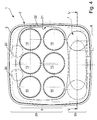
- FIG. 4 This is exemplified by a multi-layered Construction of the muffler 2 allows for what special clearly apparent from Fig. 4.
- the housing 2 at least in the region of the inlet chamber housing 21 in two levels, namely in a catalyst plane 29 and in a Outlet tube level 30, divided.
- the catalyst 9 or are its catalyst elements 10 Within the catalyst level 29 is the catalyst 9 or are its catalyst elements 10, while in the outlet tube 30th the outlet pipe 7 is arranged. 4 extends the outlet tube 7 thus below the catalyst 9 and below the catalyst elements 10 and thus also below the inlet chamber housing 21, if any is.
- This design results in greater freedom for the design and installation of the outlet tube 7, so that this be optimized in particular with regard to its length can.
- the outlet pipe 7 extends starting at its entry end 19 with a first section 31 in the collection chamber 18, in a second section 32 in the damping chamber 26 and with a third portion 33rd again in the collection chamber 18 and in the exit chamber 15, from where the outlet pipe 7 from the housing 2, through the Outlet bottom 5 exits and ends at the outlet end 8.
- the in arranged the collection chamber 18 and the entrance end 19th having first portion 31 is with a perforation 34th provided here schematically indicated with few breakthroughs is.
- This perforation 34 allows the inflow of exhaust gas from the collection chamber 18 in the outlet pipe. 7 in addition to the open entrance end 19.
- the entrance end 19 is relatively close to the partition wall 16 between the collection chamber 18 and outlet chamber 15 positioned, whereby a particularly large outlet tube length can be achieved, which is the Damping effect of the muffler 1 in the low-frequency range improved.
- the extending in the damping chamber 26 is also second section 32 of the outlet tube 7 with a Perforation 35 provided, which also only by some Breakthroughs is indicated. It is remarkable that the perforation 35 of the outlet tube 7 in the damping chamber 26 is not for a gas exchange, but for a Sound exit from the outlet pipe 7 in the damping chamber 26 is provided. In this way, the entrained in the exhaust gas Airborne sound in the damping chamber 26 and there in the Damper material 27 penetrate, resulting in an effective Can achieve damping of airborne sound. According to her different functions are the perforations 34 and 35 of the two pipe sections 31 and 32 different dimensioned. So are the opening cross sections at the perforation 34 of the first pipe section 31 within the collection chamber 18 larger dimensions than those of the perforation 35 of the second pipe section 32 within the damping chamber 26th
- the muffler 1 according to the invention also has a reduced structure-borne sound radiation to the outside and one improved heat balance.
- This is achieved by a double-walled design of the housing 2.
- the jacket 3 double-walled, so with two individual walls 3a and 3b configured, wherein between the individual walls 3a, 3b a Insulation liner 36 is arranged.
- This insulation insert 36 is mainly used for thermal insulation and can additionally be designed sound-absorbing.
- Analogous is also the inlet bottom 4 double-walled, so with two individual walls 4a and 4b configured. It is also between the Single walls 4a and 4b of the inlet floor 4 a corresponding Insulation insert 36 introduced.
- FIGS. 1 and 2 and the jacket 22nd the inlet chamber housing 21 designed double-walled. Between the individual walls 22a and 22b of the shell 22 is located then again a corresponding insulation insert 36.
- Figs. 1 to 3 is further the inlet funnel 6 double-walled designed so that a jacket 37 of the Inlet funnel 6 between its individual walls 37a and 37b again receives a suitable insulating liner 36.
- the housing 2 in addition to the Entry chamber housing 21, that is substantially in the Auslressebene 30 contain a further chamber 39, the of the adjacent damping chamber 26 by another Partition 38 is separated.
- this additional chamber 39 it can be another damping chamber, the Accordingly, it can be filled with damping material 27.
- the partition wall 38 may be perforated. It essentially serves for fixing the position of the outlet tube 7 and the inlet chamber housing 21 in the housing 2.
- the silencer 1 according to the invention with integrated catalyst 9 works as follows:
- the exhaust gases flow through the inlet funnel 6 in the inlet chamber 11 a.
- the exhaust gases can be treated with urea or be enriched with ammonia.
- the exhaust gases are distributed as evenly as possible on the inlet ends 12 of the catalyst elements 10. Since the Entry chamber 11 according to the invention designed leak-free is, there is no other possibility for the exhaust gases Leave entry chamber 11. Thus, all flow through Exhaust gases, the catalyst elements 10th
- the exhaust gases get into the Exit chamber 15. From the outlet chamber 15 enter the Exhaust gases through the partition 16 into the collection chamber 18. Von the collection chamber 18 pass the exhaust gases through the inlet end 19 and through the perforation 34 in the outlet pipe. 7 Through the outlet pipe 7, the exhaust gases from the housing. 2 led out.
- the perforation 35 within the sound attenuation chamber 26 allows a sound in the Damping material 27, which in particular higher interference frequencies be absorbed.
Abstract
Description
Die vorliegende Erfindung betrifft einen Schalldämpfer mit integriertem Katalysator für einen Abgasstrang einer Brennkraftmaschine, insbesondere in einem Kraftfahrzeug.The present invention relates to a muffler with integrated catalytic converter for an exhaust system of an internal combustion engine, especially in a motor vehicle.
Ein Abgasstrang einer Brennkraftmaschine wird regelmäßig mit wenigstens einem Schalldämpfer versehen, um die Geräuschemission der Brennkraftmaschine durch den Abgasstrang zu reduzieren. Des Weiteren wird im Abgasstrang der Brennkraftmaschine regelmäßig zumindest ein Katalysator angeordnet, um die Schadstoffemissionen der Brennkraftmaschine zu reduzieren. Für die Unterbringung der einzelnen Komponenten des Abgasstrangs steht insbesondere bei Kraftfahrzeugen häufig wenig Bauraum zur Verfügung. Dabei ist es grundsätzlich möglich, einen Katalysator raumsparend innerhalb eines Schalldämpfers anzuordnen. Zweckmäßig kann es sich dabei um einen Katalysator handeln, der in einer an sich bestehende Abgasanlage zusätzlich eingebaut werden soll, wie z.B. ein sogenannter SCR-Katalysator. Mit Hilfe eines derartigen SCR-Katalysators können NOx-Anteile der Abgase zu H2O und N2 reduziert werden, wenn stromauf des SCR-Katalysators Harnstoff oder Ammoniak geregelt eindosiert wird. An exhaust system of an internal combustion engine is regularly provided with at least one muffler to reduce the noise emission of the internal combustion engine through the exhaust system. Furthermore, at least one catalytic converter is regularly arranged in the exhaust system of the internal combustion engine in order to reduce the pollutant emissions of the internal combustion engine. For the housing of the individual components of the exhaust system is often little space available, especially in motor vehicles. It is basically possible to arrange a catalyst space-saving within a muffler. Expediently, this may be a catalyst which is to be additionally installed in an exhaust system which is per se, such as, for example, a so-called SCR catalytic converter. By means of such an SCR catalyst, NO x contents of the exhaust gases can be reduced to H 2 O and N 2 if urea or ammonia is metered in upstream of the SCR catalyst.
Die vorliegende Erfindung beschäftigt sich mit dem Problem, für einen Schalldämpfer der eingangs genannten Art eine verbesserte Ausführungsform anzugeben, bei der insbesondere die Effizienz des integrierten Katalysators verbessert ist.The present invention deals with the problem for a silencer of the type mentioned an improved Specify embodiment, in particular the Efficiency of the integrated catalyst is improved.
Dieses Problem wird erfindungsgemäß durch den Gegenstand des unabhängigen Anspruches gelöst. Vorteilhafte Ausführungsformen sind Gegenstand der abhängigen Ansprüche.This problem is inventively achieved by the subject matter of independent claim solved. Advantageous embodiments are the subject of the dependent claims.
Die vorliegende Erfindung beruht auf dem allgemeinen Gedanken, eine Eintrittskammer, in welche die dem Schalldämpfer zugeführten Abgase eintreten und von welcher die Abgase in wenigstens ein Katalysatorelement eintreten, im Übrigen hermetisch abzudichten. Auf diese Weise können die Abgase die Eintrittskammer nur durch das wenigstens eine Katalysatorelement verlassen. Insbesondere wird dadurch eine Umströmung bzw. ein Bypass des wenigstens einen Katalysatorelements vermieden. Durch die erfindungsgemäße Bauweise wird somit eine leckagefreie Eintrittskammer bereit gestellt, wodurch die Abgasströmung zwangsläufig durch das wenigstens eine Katalysatorelement hindurch geführt wird. Auf diese Weise ist sichergestellt, dass im wenigstens einen Katalysatorelement eine möglichst hohe Konversion der Schadstoffe erfolgen kann. Die Effektivität des in den Schalldämpfer integrierten Katalysators wird dadurch erheblich verbessert. Der erfindungsgemäße Schalldämpfer unterscheidet sich somit grundsätzlich von herkömmlichen Schalldämpfern, bei denen eine hermetische Abdichtung des Eintrittsbereichs nicht erforderlich ist. The present invention is based on the general idea an inlet chamber into which the muffler supplied exhaust gases enter and from which the exhaust gases in at least one catalyst element enter, otherwise hermetically seal. In this way, the exhaust gases can Entry chamber only through the at least one catalyst element leave. In particular, this is a flow around or a bypass of the at least one catalyst element avoided. Thus, by the construction according to the invention a leak-free inlet chamber provided by the exhaust gas flow inevitably through the at least one catalyst element is guided through. That way is ensures that in at least one catalyst element the highest possible conversion of pollutants takes place can. The effectiveness of integrated into the muffler Catalyst is thereby significantly improved. The inventive Muffler is thus fundamentally different of conventional mufflers, where one hermetic sealing of the entry area is not required is.
Bei einer vorteilhaften Ausführungsform kann die Eintrittskammer in einem Eintrittskammergehäuse ausgebildet sein, das als separates Bauteil in das Gehäuse des Schalldämpfers eingesetzt ist. Ein derartiges separates Eintrittskammergehäuse lässt sich einfach vorfertigen und mit der erforderlichen Dichtigkeit versehen. Für den Schalldämpfer ergibt sich somit eine vereinfachte Bauweise bei verbesserter Dichtungswirkung.In an advantageous embodiment, the inlet chamber be formed in an inlet chamber housing, the used as a separate component in the housing of the muffler is. Such a separate inlet chamber housing can be easily prefabricated and with the required Provided tightness. For the silencer thus results a simplified design with improved sealing effect.
Innerhalb des Gehäuses verläuft ein Auslaßrohr, das an der Ausgangsseite des Gehäuses aus diesem herausgeführt ist. Gemäß einer bevorzugten Ausführungsform erstreckt sich dieses Auslaßrohr im Gehäuse innerhalb einer anderen Ebene als das wenigstens eine Katalysatorelement. Auf diese Weise ergibt sich eine vereinfachte Bauweise für den Schalldämpfer, da das Auslaßrohr in der ihm zugeordneten Ebene beliebig, also unabhängig von dem wenigstens einen Katalysatorelement im Gehäuse verlegt werden kann. Auf diese Weise kann insbesondere für das Auslaßrohr eine erforderliche große Länge innerhalb des Gehäuses erzielt werden, die für eine gewünschte Schalldämpfungswirkung besonders vorteilhaft ist.Within the housing extends an outlet pipe, which at the Output side of the housing is led out of this. According to a preferred embodiment, this extends Outlet tube in the housing within a different plane than that at least one catalyst element. In this way results itself a simplified design for the muffler because the outlet pipe in the plane assigned to him arbitrarily, ie independent of the at least one catalyst element in Housing can be laid. In this way, in particular for the outlet pipe a required large length within the housing can be achieved for a desired Sound damping effect is particularly advantageous.
Während bei einem herkömmlichen Schalldämpfer ein Einlaßboden oder ein Auslaßboden durch Bördelung oder durch einzelne Schweißpunkte mit einem Mantel des Gehäuses verbunden ist, kann die Eintrittskammer bei einer bevorzugten Ausführungsform der vorliegenden Erfindung mittels Lötverbindungen und/oder Schweißverbindungen abgedichtet sein, die den Einlaßtrichter und/oder jedes Katalysatorelement und/oder die Eintrittskammer gegenüber dem Gehäuse ringförmig umschließen. Die Abdichtung der Eintrittskammer wird hier durch eine aufwendigere Verbindungstechnik realisiert, wodurch die verwendete Verbindung jedoch eine Doppelfunktion erhält, sodass der Schalldämpfer insgesamt wirtschaftlich herstellbar ist.While in a conventional muffler an inlet bottom or an outlet bottom by crimping or by individual Welding points is connected to a jacket of the housing, may be the inlet chamber in a preferred embodiment the present invention by means of solder joints and / or welded joints sealing the inlet funnel and / or each catalyst element and / or the Enclose the inlet chamber in an annular manner relative to the housing. The sealing of the inlet chamber is here by a realized more complex connection technology, whereby the used However, the connection gets a double function, so that the muffler is economically producible overall.
Weitere wichtige Merkmale und Vorteile der Erfindung ergeben sich aus den Unteransprüchen, aus den Zeichnungen und aus der zugehörigen Figurenbeschreibung anhand der Zeichnungen.Further important features and advantages of the invention result from the subclaims, from the drawings and from the associated figure description with reference to the drawings.
Es versteht sich, dass die vorstehend genannten und die nachstehend noch zu erläuternden Merkmale nicht nur in der jeweils angegebenen Kombination, sondern auch in anderen Kombinationen oder in Alleinstellung verwendbar sind, ohne den Rahmen der vorliegenden Erfindung zu verlassen.It is understood that the above and the hereinafter to be explained features not only in the each specified combination, but also in others Combinations or alone, without to leave the scope of the present invention.
Ein bevorzugtes Ausführungsbeispiel der Erfindung ist in den Zeichnungen dargestellt und wird in der nachfolgenden Beschreibung näher erläutert, wobei sich gleiche Bezugszeichen auf gleiche oder funktional gleiche oder ähnliche Bauteile beziehen.A preferred embodiment of the invention is in the Drawings are shown in the description below explained in more detail, wherein the same reference numerals to identical or functionally identical or similar components Respectively.
Es zeigen, jeweils schematisch,
- Fig. 1 bis 3
- jeweils einen Längsschnitt durch einen Schalldämpfer nach der Erfindung, bei unterschiedlichen Ausführungsformen,
- Fig. 4
- einen Querschnitt durch den Schalldämpfer,
- Fig. 5
- eine Schnittansicht entsprechend den Schnittlinien V in Fig. 4 des Schalldämpfers.
- Fig. 1 to 3
- in each case a longitudinal section through a silencer according to the invention, in different embodiments,
- Fig. 4
- a cross section through the muffler,
- Fig. 5
- a sectional view corresponding to the section lines V in Fig. 4 of the muffler.
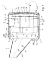
Entsprechend Fig. 1 weist ein erfindungsgemäßer Schalldämpfer
1 ein Gehäuse 2 auf, das insbesondere eine zylindrische
Gestalt besitzt. Das Gehäuse 2 umfasst einen Mantel 3 sowie
einen Einlaßboden 4 und einen Auslaßboden 5. In Bereich des
Einlaßbodens 4, also eingangsseitig ist das Gehäuse 2 mit
einem Einlaßtrichter 6 ausgestattet, der sich von einer
nicht gezeigten Abgasleitung zum Gehäuse 2 hin aufweitet. Im
Bereich des Auslaßbodens 5, also ausgangsseitig ist das Gehäuse
2 mit einem Auslaßrohr 7 ausgestattet, das ebenfalls
zu einer Abgasleitung führen kann oder dessen Austrittsende
8 (vgl. Fig. 5) den Abgasaustritt eines nicht gezeigten Abgasstrangs
bildet, in den der Schalldämpfer 1 eingebaut ist.
Dieser Abgasstrang gehört zu einer Brennkraftmaschine und
führt deren Abgase von deren Brennräumen in die Umgebung.
Zweckmäßig ist diese Brennkraftmaschine dabei in einem
Kraftfahrzeug, insbesondere in einem Nutzfahrzeug, angeordnet.According to Fig. 1, an inventive silencer
1 a
In den Schalldämpfer 1 ist ein Katalysator 9 integriert. Zu
diesem Zweck enthält der Schalldämpfer 1 in seinem Gehäuse 2
wenigstens ein Katalysatorelement 10. Im gezeigten bevorzugten
Ausführungsbeispiel sind mehrere, hier exemplarisch
sechs, Katalysatorelemente 10 vorgesehen, die in ihrer Gesamtheit
den Katalysator 9 bilden. Dementsprechend ist der
Katalysator 9 in den Fig. jeweils mit einer geschweiften
Klammer gekennzeichnet. Diese Katalysatorelemente 10 können
als Trägermaterial wahlweise ein Keramik- oder Metall-Substrat
aufweisen.In the muffler 1, a
Die Katalysatorelemente 10 sind dabei im Gehäuse 2 so angeordnet,
dass sie parallel durchströmbar sind.The
Im Gehäuse 2 ist eine Eintrittskammer 11 ausgebildet, der
über den Einlaßtrichter 6 die Abgase zugeführt werden. Die
Katalysatorelemente 10 sind mit ihren Eintrittsenden 12 jeweils
an die Eintrittskammer 11 angeschlossen. Im vorliegenden
Fall durchdringen die Katalysatorelemente 10 mit ihren
Eintrittsenden 12 eine Trennwand 13, welche die Eintrittskammer
11 an einer dem Einlaßtrichter 6 gegenüberliegenden
Seite verschließt. Dabei sind die Katalysatorelemente 10
durch diese Trennwand 13 hindurchgeführt. Diese Durchführung
durch die Trennwand 13 ist dabei gasdicht gestaltet und insbesondere
mittels einer hier nicht dargestellten Lötverbindung
oder Schweißverbindung realisiert, die ringförmig und
geschlossen das jeweilige Katalysatorelement 10 entlang der
Trennwand 13 umfasst.In the
Jedes Katalysatorelement 10 mündet mit seinem jeweiligen
Austrittsende 14 in einer Austrittskammer 15, die einerseits
vom Auslaßboden 5 und diesem gegenüberliegend von einer weiteren
Trennwand 16 begrenzt ist. Die Katalysatorelemente 10
weisen an ihren Austrittsenden 14 jeweils eine ringförmige
Perforation 17 auf. Diese Bauweise bewirkt eine Dämpfung von
Gaspulsationen in der Austrittskammer 15. Hierdurch gelingt
es, die Körperschallanregung am Auslaßboden 5 zu reduzieren.
Zwischen den beiden Trennwänden 13 und 16, also zwischen der
Eintrittskammer 11 und der Austrittskammer 15 ist eine Sammelkammer
18 angeordnet, in welcher sich ein Eintrittsende
19 (siehe auch Fig. 5) des Auslaßrohrs 7 befindet. Damit das
Abgas von der Austrittskammer 15 in die Sammelkammer 18 gelangt,
ist die dazwischen angeordnete Trennwand 16 gasdurchlässig,
insbesondere perforiert ausgestaltet. Zusätzlich oder
alternativ kann diese Trennwand 16 auch mit wenigstens
einer Durchgangsöffnung 20 (vgl. Fig. 4) ausgestattet sein.Each
Erfindungswesentlich ist nun, dass die Eintrittskammer 11
gasdicht ausgestaltet ist, so dass das über den Einlaßtrichter
6 zugeführte Abgas ausschließlich über die Katalysatorelemente
10 wieder aus der Eintrittskammer 11 austreten
kann. Durch die gasdichte Ausführung der Eintrittskammer 11
kann das Entweichen von Abgas in die Umgebung des Schalldämpfers
1 sowie eine Umgehung der Katalysatorelemente 10,
also ein Entweichen in die Sammelkammer 18 vermieden werden.
Eine solche hermetisch dichte Eintrittskammer 11 ist für eine
bevorzugte Anwendungsform des Schalldämpfers 1 von besonderer
Bedeutung, nämlich dann, wenn der darin integrierte
Katalysator 9 als SCR-Katalysator ausgestaltet ist und zur
Umwandlung von Harnstoff oder Ammoniak dient, das stromauf
des Schalldämpfers 1 in den Abgasstrang eingebracht wird.
Zur Ausgestaltung eines SCR-Katalysators 9 werden dementsprechend
SCR-Katalysatorelemente 10 verwendet. It is essential to the invention that the
Mit Hilfe der vorstehend genannten Additive können durch die
SCR-Technik, also durch selektive katalytische Reaktion oder
Reduktion die NOx-Anteile im Abgas zu H2O und N2 reduziert
werden. Damit dieser SCR-Katalysator 9 besonders effektiv
arbeitet und der zugemischte Harnstoff bzw. das zugemischte
Ammoniak nicht in die Umgebung gelangt, ist bei der Erfindung
die Eintrittskammer 11 leckagefrei ausgestaltet. Erreicht
wird dies beispielsweise dadurch, dass bei den Ausführungsformen
der Fig. 1 und 2 der Einlaßtrichter 6 mit wenigstens
einer ringförmig und geschlossen entlang des Einlaßbodens
4 umlaufenden, hier nicht gezeigten Schweißverbindung
oder Lötverbindung mit dem Einlaßboden 4 verbunden ist.
Des weiteren ist auch die zwischen Eintrittskammer 11 und
Sammelkammer 18 angeordnete Trennwand 13 ringförmig geschlossen
umlaufend nach außen abgedichtet.By means of the abovementioned additives, the SCR technique, that is to say by selective catalytic reaction or reduction, can reduce the NO x components in the exhaust gas to H 2 O and N 2 . In order for this SCR
Bei den Ausführungsformen der Fig. 1 und 2 ist die Eintrittskammer
11 in einem separaten Eintrittskammergehäuse 21
ausgebildet, das auch im Querschnitt gemäß Fig. 4 erkennbar
ist. Dieses separate Eintrittskammergehäuse 21 ist als solches
vollständig in das Gehäuse 2 des Schalldämpfers 1 eingesetzt.
Das Eintrittskammergehäuse 21 besitzt ebenfalls einen
Mantel 22 und ist ausgangsseitig durch die Trennwand 13
verschlossen. Eingangsseitig ist das Eintrittskammergehäuse
21 durch den Einlaßboden 4 verschlossen, der mit dem übrigen
Einlaßboden 4' des Gehäuses 2 verbunden, insbesondere dicht
darin eingesetzt ist. Zum eingangsseitigen Verschließen des
Gehäuses 2 ist somit ein zusätzlicher, entsprechend geformter
Einlaßboden 4` erforderlich. Ebenso ist eine Ausführungsform
möglich, bei der das Eintrittskammergehäuse 21 und
das Gehäuse 2 durch einen gemeinsamen Einlaßboden verschlossen
sind und/oder bei der das Eintrittskammergehäuse 21 einen
eigenen Auslaßboden aufweist.In the embodiments of Figs. 1 and 2, the
Das separat hergestellte Eintrittskammergehäuse 21 lässt
sich insbesondere einfach vorfertigen, wodurch die erwünschte
Dichtigkeit für die Eintrittskammer 11 relativ preiswert
realisierbar ist. Zweckmäßig ist der Einlaßtrichter 6 an
dieses Eintrittskammergehäuse 21 angebaut, so dass ein Austrittsende
23 des Einlaßtrichters 6 in der Eintrittskammer
11 mündet.The separately produced
Im Unterschied dazu ist bei der Ausführungsform gemäß Fig. 3
die Eintrittskammer 11 in einem das Austrittsende 23 des
Einlaßtrichters 6 enthaltenden Endabschnitt 24 des Einlaßtrichters
6 ausgebildet. Mit anderen Worten, die Katalysatorelemente
10 erstrecken sich mit ihren Eintrittsenden 12
bis zum Austrittsende 23 des Einlaßtrichters 6. Insbesondere
kann gemäß Fig. 3 der Einlaßtrichter 6 quasi den Einlaßboden
des Eintrittskammergehäuses 21 bilden oder entbehrlich machen.
Um hier noch eine hinreichende Aufteilung der den Katalysatorelementen
10 zugeführten Abgasströmung auf die einzelnen
Katalysatorelemente 10 bzw. auf deren durchströmbare
Querschnitte zu erreichen, kann im Einlaßtrichter 6 optional
ein Verteiler- und/oder Mischelement 25 angeordnet sein, das
hier mit unterbrochener Linie dargestellt ist. Dieses Verteiler-
und/oder Mischelement 25 unterstützt beispielsweise
die Aufweitung der ankommenden Abgasströmung und ermöglicht
eine möglichst gleichmäßige Anströmung der einzelnen Eintrittsenden
12 der Katalysatorelemente 10. Es ist klar, dass
ein derartiges Verteiler- und/oder Mischelement 25 auch bei
den Ausführungsformen der Fig. 1 und 2 im Einlaßtrichter 6
angeordnet sein kann.In contrast, in the embodiment according to FIG. 3
the
Bei der Ausführungsform gemäß Fig. 1 ist die Eintrittskammer
11 vergleichsweise großvolumig ausgestaltet, wodurch in der
Eintrittskammer 11 eine relativ homogene Vermischung und eine
vergleichsweise gleichmäßige Aufteilung der ankommenden
Abgase auf die einzelnen Katalysatorelemente 10 realisierbar
ist.In the embodiment according to FIG. 1, the
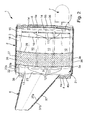
Im Unterschied dazu kann bei den Ausführungsformen der Fig.
2 und 3 die Eintrittskammer 11 kleiner dimensioniert sein.
Bei diesen Ausführungsformen ist im Gehäuse 2 zusätzlich eine
Dämpfungskammer 26 ausgebildet, in der ein durch eine
Schraffur angedeutetes Dämpfungsmaterial 27 angeordnet ist.
Diese Dämpfungskammer 26 ist z.B. zwischen der Eintrittskammer
11 und der Austrittskammer 15 und außerdem zweckmäßig
zwischen der Eintrittskammer 11 und der Sammelkammer 18 angeordnet.
Zu diesem Zweck ist eine weitere Trennwand 28 vorgesehen,
welche die Sammelkammer 18 von der Dämpfungskammer
26 trennt. Sofern - wie bei der Ausführungsform gemäß Fig. 2
- ein Eintrittskammergehäuse 21 vorgesehen ist, kann sich
die Dämpfungskammer 26 innerhalb des Gehäuses 2 außerdem
seitlich des Eintrittskammergehäuses 21 bis zum Einlaßboden
4` erstrecken. Dies wird beispielsweise durch eine mehrschichtige
Bauweise des Schalldämpfers 2 ermöglicht, was besonders
deutlich aus Fig. 4 hervorgeht. Dort ist das Gehäuse
2 zumindest im Bereich des Eintrittskammergehäuses 21 in
zwei Ebenen, nämlich in eine Katalysatorebene 29 und in eine
Auslaßrohrebene 30, unterteilt. Innerhalb der Katalysatorebene
29 ist der Katalysator 9 bzw. sind dessen Katalysatorelemente
10 angeordnet, während in der Auslaßrohrebene 30
das Auslaßrohr 7 angeordnet ist. Gemäß Fig. 4 erstreckt sich
das Auslaßrohr 7 somit unterhalb des Katalysators 9 bzw. unterhalb
der Katalysatorelemente 10 und somit auch unterhalb
des Eintrittskammergehäuses 21, sofern ein solches vorhanden
ist. Durch diese Bauweise ergibt sich eine größere Freiheit
für die Gestaltung und Verlegung des Auslaßrohrs 7, so dass
dieses insbesondere hinsichtlich seiner Länge optimiert werden
kann.In contrast, in the embodiments of FIG.
2 and 3, the
Entsprechend Fig. 5 erstreckt sich das Auslaßrohr 7 beginnend
an seinem Eintrittsende 19 mit einem ersten Abschnitt
31 in der Sammelkammer 18, in einem zweiten Abschnitt 32 in
der Dämpfungskammer 26 und mit einem dritten Abschnitt 33
wieder in der Sammelkammer 18 sowie in der Austrittskammer
15, von wo aus das Auslaßrohr 7 aus dem Gehäuse 2, durch den
Auslaßboden 5 austritt und am Austrittsende 8 endet. Der in
der Sammelkammer 18 angeordnete und das Eintrittsende 19
aufweisende erste Abschnitt 31 ist mit einer Perforation 34
versehen, die hier mit wenigen Durchbrüchen schematisch angedeutet
ist. Diese Perforation 34 ermöglicht die Einströmung
von Abgas aus der Sammelkammer 18 in das Auslaßrohr 7
zusätzlich zum offenen Eintrittsende 19. Das Eintrittsende
19 ist dabei relativ nahe an der Trennwand 16 zwischen Sammelkammer
18 und Austrittskammer 15 positioniert, wodurch
eine besonders große Auslaßrohrlänge erzielbar ist, was die
Dämpfungswirkung des Schalldämpfers 1 im tieffrequenten Bereich
verbessert.According to Fig. 5, the
Des weiteren ist auch der sich in der Dämpfungskammer 26 erstreckende
zweite Abschnitt 32 des Auslaßrohrs 7 mit einer
Perforation 35 versehen, die ebenfalls nur durch einige
Durchbrüche angedeutet ist. Bemerkenswert ist hierbei, dass
die Perforation 35 des Auslaßrohrs 7 in der Dämpfungskammer
26 nicht für einen Gasaustausch dient, sondern für einen
Schallaustritt aus dem Auslaßrohr 7 in die Dämpfungskammer
26 vorgesehen ist. Auf diese Weise kann der im Abgas mitgeführte
Luftschall in die Dämpfungskammer 26 und dort in das
Dämpfungsmaterial 27 eindringen, wodurch sich eine effektive
Bedämpfung des Luftschalls erzielen lässt. Entsprechend ihrer
unterschiedlichen Funktionen sind die Perforationen 34
und 35 der beiden Rohrabschnitte 31 und 32 unterschiedlich
dimensioniert. So sind die Öffnungsquerschnitte bei der Perforation
34 des ersten Rohrabschnitts 31 innerhalb der Sammelkammer
18 größer dimensioniert als diejenigen der Perforation
35 des zweiten Rohrabschnitts 32 innerhalb der Dämpfungskammer
26.Furthermore, the extending in the damping
Der erfindungsgemäße Schalldämpfer 1 besitzt außerdem eine
reduzierte Körperschallabstrahlung nach außen sowie einen
verbesserten Wärmehaushalt. Erreicht wird dies durch eine
doppelwandige Ausführung des Gehäuses 2. Insbesondere ist
der Mantel 3 doppelwandig, also mit zwei Einzelwänden 3a und
3b ausgestaltet, wobei zwischen den Einzelwänden 3a, 3b eine
Isolationseinlage 36 angeordnet ist. Diese Isolationseinlage
36 dient hauptsächlich zur thermischen Isolierung und kann
zusätzlich schalldämpfend ausgestaltet sein. Analog dazu ist
auch der Einlaßboden 4 doppelwandig, also mit zwei Einzelwänden
4a und 4b ausgestaltet. Dabei ist auch zwischen den
Einzelwänden 4a und 4b des Einlaßbodens 4 eine entsprechende
Isolationseinlage 36 eingebracht. In entsprechender Weise
ist auch der Auslaßboden 5 doppelwandig ausgestaltet, wobei
zwischen den Einzelwänden 5a und 5b des Auslaßbodens 5 ebenfalls
eine entsprechende Isolationseinlage 36 eingebracht
ist. Entsprechend den Fig. 1 und 2 ist auch der Mantel 22
des Eintrittskammergehäuses 21 doppelwandig ausgestaltet.
Zwischen den Einzelwänden 22a und 22b des Mantels 22 befindet
sich dann wieder eine entsprechende Isolationseinlage
36. Gemäß den Fig. 1 bis 3 ist des weiteren der Einlaßtrichter
6 doppelwandig ausgestaltet, so dass ein Mantel 37 des
Einlaßtrichters 6 zwischen seinen Einzelwänden 37a und 37b
wieder eine geeignete Isolationseinlage 36 aufnimmt.The muffler 1 according to the invention also has a
reduced structure-borne sound radiation to the outside and one
improved heat balance. This is achieved by a
double-walled design of the
Entsprechend den Fig. 1 und 5 kann das Gehäuse 2 neben dem
Eintrittskammergehäuse 21, also im wesentlichen in der Auslaßrohrebene
30 eine weitere Kammer 39 enthalten, die von
der dazu benachbarten Dämpfungskammer 26 durch eine weitere
Trennwand 38 getrennt ist. Bei dieser zusätzlichen Kammer 39
kann es sich um eine weitere Dämpfungskammer handeln, die
dementsprechend mit Dämpfungsmaterial 27 gefüllt sein kann.
Die Trennwand 38 kann perforiert sein. Sie dient im wesentlichen
zur Lagefixierung des Auslaßrohrs 7 sowie des Eintrittskammergehäuses
21 im Gehäuse 2.According to FIGS. 1 and 5, the
Der erfindungsgemäße Schalldämpfer 1 mit integriertem Katalysator
9 arbeitet wie folgt:The silencer 1 according to the invention with
Im Betrieb der Brennkraftmaschine strömen die Abgase durch
den Einlaßtrichter 6 in die Eintrittskammer 11 ein. Dabei
können die Abgase bei einer bevorzugten Anwendung mit Harnstoff
oder mit Ammoniak angereicht sein. In der Eintrittskammer
11 verteilen sich die Abgase möglichst gleichmäßig
auf die Eintrittsenden 12 der Katalysatorelemente 10. Da die
Eintrittskammer 11 erfindungsgemäß leckagefrei ausgestaltet
ist, besteht für die Abgase keine andere Möglichkeit, die
Eintrittskammer 11 zu verlassen. Somit durchströmen sämtliche
Abgase die Katalysatorelemente 10.During operation of the internal combustion engine, the exhaust gases flow through
the
Durch die Katalysatorelemente 10 gelangen die Abgase in die
Austrittskammer 15. Von der Austrittskammer 15 gelangen die
Abgase durch die Trennwand 16 in die Sammelkammer 18. Von
der Sammelkammer 18 gelangen die Abgase durch das Eintrittsende
19 sowie durch die Perforation 34 in das Auslaßrohr 7.
Durch das Auslaßrohr 7 werden die Abgase aus dem Gehäuse 2
herausgeführt. Die Perforation 35 innerhalb der Schalldämpfungskammer
26 ermöglicht dabei einen Schallaustrag in das
Dämpfungsmaterial 27, wodurch insbesondere höhere Störfrequenzen
absorbiert werden.Through the
Claims (17)
dadurch gekennzeichnet, dass die Eintrittskammer (11) in einem Eintrittskammergehäuse (21) ausgebildet ist, das als separates Bauteil in das Gehäuse (2) eingesetzt ist.Silencer according to claim 1,
characterized in that the inlet chamber (11) is formed in an inlet chamber housing (21) which is inserted as a separate component in the housing (2).
dadurch gekennzeichnet, dass die Eintrittskammer (11) durch einen das Austrittsende (23) des Einlaßtrichters (6) enthaltenden Abschnitt (24) des Einlaßtrichters (6) gebildet ist.Silencer according to claim 1,
characterized in that the inlet chamber (11) is formed by a portion (24) of the inlet funnel (6) containing the exit end (23) of the inlet funnel (6).
dadurch gekennzeichnet, dass die Austrittskammer (15) durch eine Trennwand (16) mit einer Sammelkammer (18) kommuniziert, wobei ein Eintrittsende (19) des Auslaßrohrs (7) mit der Sammelkammer (18) kommuniziert.Silencer according to one of claims 1 to 3,
characterized in that the exit chamber (15) communicates with a collection chamber (18) through a divider wall (16), an entry end (19) of the exit duct (7) communicating with the collection chamber (18).
dadurch gekennzeichnet, dass wenigstens zwei parallel durchströmbare Katalysatorelemente (10) vorgesehen sind.Silencer according to one of claims 1 to 4,
characterized in that at least two parallel durchströmbare catalyst elements (10) are provided.
dadurch gekennzeichnet, dass im Einlaßtrichter (6) ein Verteiler- und/oder Mischelement (25) angeordnet ist, welches das ankommende Abgas auf das oder die Eintrittsenden (12) des oder der Katalysatorelemente (10) verteilt. Silencer according to one of claims 1 to 5,
characterized in that in the inlet funnel (6) a distributor and / or mixing element (25) is arranged, which distributes the incoming exhaust gas to the one or more inlet ends (12) of the catalyst element or elements (10).
dadurch gekennzeichnet, dass jedes Katalysatorelement (10) an seinem Austrittsende (14) eine ringförmige Perforation (17) aufweist.Silencer according to one of claims 1 to 6,
characterized in that each catalyst element (10) has at its outlet end (14) an annular perforation (17).
dadurch gekennzeichnet, dass die Trennwand (16) zwischen Austrittskammer (15) und Sammelkammer (18) perforiert ist und/oder wenigstens eine Durchgangsöffnung (20) enthält.Silencer at least according to claim 4,
characterized in that the dividing wall (16) between the outlet chamber (15) and the collecting chamber (18) is perforated and / or at least one passage opening (20).
dadurch gekennzeichnet, dass die Sammelkammer (18) zwischen der Eintrittskammer (11) und der Austrittskammer (15) angeordnet ist.Silencer at least according to claim 4,
characterized in that the collecting chamber (18) between the inlet chamber (11) and the outlet chamber (15) is arranged.
dadurch gekennzeichnet,
characterized,
dadurch gekennzeichnet, dass zumindest ein Teil der Dämpfungskammer (26) zwischen der Sammelkammer (18) und der Eintrittskammer (11) angeordnet ist. Silencer according to claim 10,
characterized in that at least a part of the damping chamber (26) is arranged between the collecting chamber (18) and the inlet chamber (11).
dadurch gekennzeichnet,
characterized,
dadurch gekennzeichnet, dass die Perforation (34) des Auslaßrohrs (7) in der Sammelkammer (18) größere Öffnungsquerschnitte aufweist als die Perforation (35) des Auslaßrohrs (7) in der Dämpfungskammer (26) .Silencer according to claims 10 and 12,
characterized in that the perforation (34) of the outlet tube (7) in the collecting chamber (18) has larger opening cross-sections than the perforation (35) of the outlet tube (7) in the damping chamber (26).
dadurch gekennzeichnet, dass sich das Auslaßrohr (7) im Gehäuse (2) innerhalb einer anderen Ebene (30) erstreckt als das wenigstens eine Katalysatorelement (10).Silencer according to one of claims 1 to 13,
characterized in that the outlet tube (7) in the housing (2) extends within a different plane (30) than the at least one catalyst element (10).
dadurch gekennzeichnet, dass das wenigstens eine Katalysatorelement (10) ein SCR-Katalysatorelement ist.Silencer according to one of claims 1 to 14,
characterized in that the at least one catalyst element (10) is an SCR catalyst element.
dadurch gekennzeichnet, dass der Einlaßtrichter (6) und/oder das Gehäuse (2) und/oder das Eintrittskammergehäuse (21) und/oder ein vom Einlaßtrichter (6) durchsetzter Einlaßboden (4) des Gehäuses (2) und/oder ein vom Auslaßrohr (7) durchsetzter Auslaßboden (5) des Gehäuses (2) doppelwandig mit Isolationseinlage (36) ausgestaltet ist.Silencer according to one of claims 1 to 15,
characterized in that the inlet funnel (6) and / or the housing (2) and / or the inlet chamber housing (21) and / or one of the inlet funnel (6) interspersed inlet bottom (4) of the housing (2) and / or one of the outlet tube (7) interspersed outlet bottom (5) of the housing (2) is designed double-walled with insulation insert (36).
dadurch gekennzeichnet, dass die Eintrittskammer (11) mittels Lötverbindungen und/oder mittels Schweißverbindungen abgedichtet ist, die den Einlaßtrichter (6) und/oder jedes Katalysatorelement (10) und/oder die Eintrittskammer (11) gegenüber dem Gehäuse (2) ringförmig umschließen.Silencer according to one of claims 1 to 16,
characterized in that the inlet chamber (11) is sealed by means of solder joints and / or by means of welded joints, which surround the inlet funnel (6) and / or each catalyst element (10) and / or the inlet chamber (11) with respect to the housing (2) in an annular manner.
Applications Claiming Priority (2)
| Application Number | Priority Date | Filing Date | Title |
|---|---|---|---|
| DE10356000 | 2003-11-27 | ||
| DE10356000A DE10356000B4 (en) | 2003-11-27 | 2003-11-27 | Silencer with integrated catalytic converter |
Publications (3)
| Publication Number | Publication Date |
|---|---|
| EP1536113A2 true EP1536113A2 (en) | 2005-06-01 |
| EP1536113A3 EP1536113A3 (en) | 2006-03-15 |
| EP1536113B1 EP1536113B1 (en) | 2008-08-13 |
Family
ID=34442371
Family Applications (1)
| Application Number | Title | Priority Date | Filing Date |
|---|---|---|---|
| EP04105619A Active EP1536113B1 (en) | 2003-11-27 | 2004-11-09 | Exhaust gas silencer with integrated catalyst |
Country Status (4)
| Country | Link |
|---|---|
| US (1) | US7127884B2 (en) |
| EP (1) | EP1536113B1 (en) |
| AT (1) | ATE404781T1 (en) |
| DE (2) | DE10356000B4 (en) |
Cited By (6)
| Publication number | Priority date | Publication date | Assignee | Title |
|---|---|---|---|---|
| DE102005025738A1 (en) * | 2005-06-04 | 2006-12-21 | Daimlerchrysler Ag | exhaust aftertreatment device |
| WO2008107151A1 (en) * | 2007-03-03 | 2008-09-12 | Eberspächer Unna GmbH & Co. KG | Exhaust gas aftertreatment device of a motor vehicle |
| DE102008046222A1 (en) * | 2008-09-08 | 2010-04-08 | J. Eberspächer GmbH & Co. KG | exhaust treatment device |
| US8763375B2 (en) | 2010-08-19 | 2014-07-01 | J. Eberspaecher Gmbh & Co. Kg | Exhaust gas cleaning device, exhaust system, removal method |
| US9222392B2 (en) | 2010-04-15 | 2015-12-29 | Eberspaecher Exhaust Technology Gmbh & Co. Kg | Exhaust gas treatment device |
| IT201700008995A1 (en) * | 2017-02-16 | 2018-08-16 | Xxl Marmitte Italiane S R L | CATALYST FOR HEAVY VEHICLES |
Families Citing this family (21)
| Publication number | Priority date | Publication date | Assignee | Title |
|---|---|---|---|---|
| DE102004038188A1 (en) * | 2004-08-06 | 2006-03-16 | Robert Bosch Gmbh | Sound damping device, in particular for a heater |
| US20060081416A1 (en) * | 2004-10-14 | 2006-04-20 | Nentrup Trent L | Exhaust silencer with acoustic damping mat |
| JP2006151298A (en) * | 2004-11-30 | 2006-06-15 | Honda Motor Co Ltd | Fuel cell powered vehicle |
| KR100667028B1 (en) * | 2005-10-04 | 2007-01-10 | 희성엥겔하드주식회사 | A scr catalytic converter without nh3 or urea injection |
| WO2007147119A2 (en) * | 2006-06-16 | 2007-12-21 | Robert Aratari | Combustion generator enhancement device |
| US7717205B2 (en) * | 2006-11-28 | 2010-05-18 | Caterpillar Inc. | Engine hood assembly enclosure with exhaust aftertreatment device integrated therein, and machine using same |
| DE102008022081A1 (en) * | 2008-05-05 | 2009-11-12 | J. Eberspächer GmbH & Co. KG | Exhaust gas treatment device |
| US8071037B2 (en) | 2008-06-25 | 2011-12-06 | Cummins Filtration Ip, Inc. | Catalytic devices for converting urea to ammonia |
| US20100186381A1 (en) * | 2009-01-26 | 2010-07-29 | Caterpillar Inc | Exhaust system thermal enclosure |
| US20100186394A1 (en) * | 2009-01-26 | 2010-07-29 | Caterpillar Inc. | Exhaust gas after treatment assembly |
| DE102009024718A1 (en) * | 2009-06-12 | 2010-12-16 | Emitec Gesellschaft Für Emissionstechnologie Mbh | Exhaust gas treatment device for use close to the engine |
| US8151556B2 (en) * | 2009-07-21 | 2012-04-10 | Navistar Canada, Inc. | Internal combustion engine exhaust after-treatment system and method |
| DE102010008999A1 (en) * | 2010-02-24 | 2011-08-25 | J. Eberspächer GmbH & Co. KG, 73730 | Exhaust gas treatment device |
| AT511548A1 (en) * | 2011-06-06 | 2012-12-15 | Avl List Gmbh | INTERNAL COMBUSTION ENGINE WITH AT LEAST ONE CATALYST UNIT |
| US9086007B2 (en) * | 2012-12-21 | 2015-07-21 | Caterpillar Inc. | System and method for accommodating aftertreatment bricks |
| US8978369B2 (en) | 2012-12-26 | 2015-03-17 | Caterpillar Inc. | Exhaust gas aftertreatment module |
| US9828898B2 (en) * | 2015-10-29 | 2017-11-28 | Hyundai Motor Company | Optimized structure for integrated catalytic muffler |
| JP6522032B2 (en) * | 2017-03-23 | 2019-05-29 | 本田技研工業株式会社 | Exhaust system |
| WO2019059942A1 (en) | 2017-09-25 | 2019-03-28 | Faurecia Emissions Control Technologies, Usa, Llc | Acoustic volume in hot-end of exhaust systems |
| US10941693B2 (en) | 2018-01-18 | 2021-03-09 | Faurecia Emissions Control Technologies, Usa, Llc | Vehicle frame with acoustic volume for an exhaust system |
| DE102021130365B8 (en) | 2021-11-19 | 2023-05-04 | Emission Partner GmbH & Co. KG | exhaust system |
Citations (4)
| Publication number | Priority date | Publication date | Assignee | Title |
|---|---|---|---|---|
| DE4431484A1 (en) * | 1994-09-03 | 1996-03-14 | Eberspaecher J | IC engine exhaust silencer with integrated exhaust purifying stage |
| EP0816648A1 (en) * | 1996-07-04 | 1998-01-07 | ROTH-TECHNIK AUSTRIA Gesellschaft m.b.H. | Silencer for motor vehicle |
| DE19952428A1 (en) * | 1999-10-30 | 2001-05-03 | Man Nutzfahrzeuge Ag | Method and device for the combined catalytic NOx reduction and sound attenuation of exhaust gas in the exhaust line of an internal combustion engine |
| WO2002077425A1 (en) * | 2001-02-07 | 2002-10-03 | Arvin Tehnologies Inc. | Exhaust processor with renewable particulate eliminator |
Family Cites Families (12)
| Publication number | Priority date | Publication date | Assignee | Title |
|---|---|---|---|---|
| US4209493A (en) * | 1977-07-11 | 1980-06-24 | Nelson Industries, Inc. | Combination catalytic converter and muffler for an exhaust system |
| JPS60184919A (en) * | 1984-03-01 | 1985-09-20 | Nissan Motor Co Ltd | Catalytic muffler for internal-combustion engine |
| DE3729477C3 (en) * | 1987-09-03 | 1999-09-09 | Stihl Maschf Andreas | Exhaust silencer for two-stroke engines, especially for portable tools such as chainsaws |
| DE3940747C1 (en) * | 1989-12-09 | 1990-07-12 | Mercedes-Benz Aktiengesellschaft, 7000 Stuttgart, De | |
| DE4219540B4 (en) * | 1991-06-28 | 2008-02-28 | Volkswagen Ag | Catalyst arrangement for the purification of a pulsating exhaust gas stream |
| DE4219549C2 (en) | 1992-06-15 | 1994-07-28 | Fraunhofer Ges Forschung | Process for welding workpieces |
| US5285640A (en) * | 1992-07-21 | 1994-02-15 | Olivo John R | Integrated post-engine emissions heater, catalytic converter and muffler |
| ATE193222T1 (en) * | 1995-06-28 | 2000-06-15 | Siemens Ag | METHOD AND DEVICE FOR CATALYTICALLY CLEANING THE EXHAUST GAS FROM A COMBUSTION PLANT |
| DE10042542A1 (en) * | 2000-08-30 | 2002-03-14 | Eberspaecher J Gmbh & Co | Exhaust gas cleaning system for motor vehicles, in particular diesel commercial vehicles |
| JP2002256861A (en) * | 2001-03-05 | 2002-09-11 | Honda Motor Co Ltd | Muffler device with catalyst |
| DE10123360A1 (en) * | 2001-05-14 | 2002-11-21 | Man Nutzfahrzeuge Ag | Combined exhaust gas aftertreatment / noise reduction device in the exhaust line of an internal combustion engine |
| GB0113226D0 (en) * | 2001-06-01 | 2001-07-25 | Nelson Burgess Ltd | Catalytic converter |
-
2003
- 2003-11-27 DE DE10356000A patent/DE10356000B4/en not_active Expired - Fee Related
-
2004
- 2004-11-09 DE DE502004007827T patent/DE502004007827D1/en active Active
- 2004-11-09 AT AT04105619T patent/ATE404781T1/en not_active IP Right Cessation
- 2004-11-09 EP EP04105619A patent/EP1536113B1/en active Active
- 2004-11-24 US US10/996,378 patent/US7127884B2/en active Active
Patent Citations (4)
| Publication number | Priority date | Publication date | Assignee | Title |
|---|---|---|---|---|
| DE4431484A1 (en) * | 1994-09-03 | 1996-03-14 | Eberspaecher J | IC engine exhaust silencer with integrated exhaust purifying stage |
| EP0816648A1 (en) * | 1996-07-04 | 1998-01-07 | ROTH-TECHNIK AUSTRIA Gesellschaft m.b.H. | Silencer for motor vehicle |
| DE19952428A1 (en) * | 1999-10-30 | 2001-05-03 | Man Nutzfahrzeuge Ag | Method and device for the combined catalytic NOx reduction and sound attenuation of exhaust gas in the exhaust line of an internal combustion engine |
| WO2002077425A1 (en) * | 2001-02-07 | 2002-10-03 | Arvin Tehnologies Inc. | Exhaust processor with renewable particulate eliminator |
Cited By (8)
| Publication number | Priority date | Publication date | Assignee | Title |
|---|---|---|---|---|
| DE102005025738A1 (en) * | 2005-06-04 | 2006-12-21 | Daimlerchrysler Ag | exhaust aftertreatment device |
| WO2008107151A1 (en) * | 2007-03-03 | 2008-09-12 | Eberspächer Unna GmbH & Co. KG | Exhaust gas aftertreatment device of a motor vehicle |
| US8549844B2 (en) | 2007-03-03 | 2013-10-08 | Eberspächer Exhaust Technology GmbH & Co. KG | Exhaust gas after treatment apparatus of a motor vehicle |
| DE102008046222A1 (en) * | 2008-09-08 | 2010-04-08 | J. Eberspächer GmbH & Co. KG | exhaust treatment device |
| US8388896B2 (en) | 2008-09-08 | 2013-03-05 | J. Eberspaecher Gmbh & Co. Kg | Exhaust gas retreatment device |
| US9222392B2 (en) | 2010-04-15 | 2015-12-29 | Eberspaecher Exhaust Technology Gmbh & Co. Kg | Exhaust gas treatment device |
| US8763375B2 (en) | 2010-08-19 | 2014-07-01 | J. Eberspaecher Gmbh & Co. Kg | Exhaust gas cleaning device, exhaust system, removal method |
| IT201700008995A1 (en) * | 2017-02-16 | 2018-08-16 | Xxl Marmitte Italiane S R L | CATALYST FOR HEAVY VEHICLES |
Also Published As
| Publication number | Publication date |
|---|---|
| EP1536113B1 (en) | 2008-08-13 |
| EP1536113A3 (en) | 2006-03-15 |
| DE10356000A1 (en) | 2005-07-07 |
| US7127884B2 (en) | 2006-10-31 |
| ATE404781T1 (en) | 2008-08-15 |
| US20050115229A1 (en) | 2005-06-02 |
| DE502004007827D1 (en) | 2008-09-25 |
| DE10356000B4 (en) | 2006-01-12 |
Similar Documents
| Publication | Publication Date | Title |
|---|---|---|
| DE10356000B4 (en) | Silencer with integrated catalytic converter | |
| EP1691045B1 (en) | Exhaust gas purification system | |
| DE112008002531B4 (en) | aftertreatment system | |
| EP2440759B1 (en) | Exhaust gas treatment device for use near an engine | |
| EP2233708B2 (en) | Exhaust treatment device | |
| DE19955013B4 (en) | Exhaust system of an internal combustion engine | |
| EP1357267B1 (en) | Exhaust gas treating apparatus with silencer for a diesel engine | |
| DE19900310B4 (en) | Catalytic converter for a muffler of a small motor | |
| DE102007010486A1 (en) | Exhaust gas treatment device for motor vehicle has inflow chamber further bounded by jacket part in gastight connection with bottom parts | |
| EP3704360B1 (en) | Exhaust gas system for compact and efficient aftertreatment and sound damping of the exhaust gas | |
| DE19755126B4 (en) | Catalyst arrangement with two-branch exhaust system | |
| DE60018201T2 (en) | DEVICE FOR THE SELECTIVE COOLING OF EXHAUST GASES OF A MOTOR VEHICLE ENGINE | |
| DE19626980A1 (en) | Silencers for automobiles | |
| DE102018122637A1 (en) | Silencer for an exhaust system of a motor vehicle and motor vehicle with a silencer | |
| DE10144015A1 (en) | Exhaust system for multi-cylinder internal combustion engines | |
| DE102011120221A1 (en) | Mixer for exhaust system for internal combustion engine of motor vehicle, has tubular housing with inlet and outlet, where mixing elements are arranged in flow direction of exhaust gas at inner wall of housing | |
| DE60214748T2 (en) | HOUSING ARRANGED IN AN EXHAUST SYSTEM FOR A COMBUSTION ENGINE | |
| DE2022037A1 (en) | Silencer | |
| DE102018203300B4 (en) | Arrangement of an internal combustion engine with an exhaust tract, motor vehicle and method for controlling exhaust gas aftertreatment | |
| DE10357941B4 (en) | Silencer for an exhaust system | |
| DE1426198A1 (en) | Silencer | |
| DE102009053949A1 (en) | Device for the aftertreatment of exhaust gases of an internal combustion engine | |
| DE102021130365B3 (en) | exhaust system | |
| EP1749686B1 (en) | Exhaust system for motor vehicle | |
| EP3759327B1 (en) | Device for exhaust gas aftertreatment |
Legal Events
| Date | Code | Title | Description |
|---|---|---|---|
| PUAI | Public reference made under article 153(3) epc to a published international application that has entered the european phase |
Free format text: ORIGINAL CODE: 0009012 |
|
| AK | Designated contracting states |
Kind code of ref document: A2 Designated state(s): AT BE BG CH CY CZ DE DK EE ES FI FR GB GR HU IE IS IT LI LU MC NL PL PT RO SE SI SK TR |
|
| AX | Request for extension of the european patent |
Extension state: AL HR LT LV MK YU |
|
| PUAL | Search report despatched |
Free format text: ORIGINAL CODE: 0009013 |
|
| AK | Designated contracting states |
Kind code of ref document: A3 Designated state(s): AT BE BG CH CY CZ DE DK EE ES FI FR GB GR HU IE IS IT LI LU MC NL PL PT RO SE SI SK TR |
|
| AX | Request for extension of the european patent |
Extension state: AL HR LT LV MK YU |
|
| 17P | Request for examination filed |
Effective date: 20060330 |
|
| AKX | Designation fees paid |
Designated state(s): AT BE BG CH CY CZ DE DK EE ES FI FR GB GR HU IE IS IT LI LU MC NL PL PT RO SE SI SK TR |
|
| 17Q | First examination report despatched |
Effective date: 20061130 |
|
| GRAP | Despatch of communication of intention to grant a patent |
Free format text: ORIGINAL CODE: EPIDOSNIGR1 |
|
| GRAC | Information related to communication of intention to grant a patent modified |
Free format text: ORIGINAL CODE: EPIDOSCIGR1 |
|
| GRAS | Grant fee paid |
Free format text: ORIGINAL CODE: EPIDOSNIGR3 |
|
| GRAA | (expected) grant |
Free format text: ORIGINAL CODE: 0009210 |
|
| AK | Designated contracting states |
Kind code of ref document: B1 Designated state(s): AT BE BG CH CY CZ DE DK EE ES FI FR GB GR HU IE IS IT LI LU MC NL PL PT RO SE SI SK TR |
|
| REG | Reference to a national code |
Ref country code: GB Ref legal event code: FG4D Free format text: NOT ENGLISH |
|
| REG | Reference to a national code |
Ref country code: CH Ref legal event code: EP |
|
| REG | Reference to a national code |
Ref country code: IE Ref legal event code: FG4D Free format text: LANGUAGE OF EP DOCUMENT: GERMAN |
|
| REF | Corresponds to: |
Ref document number: 502004007827 Country of ref document: DE Date of ref document: 20080925 Kind code of ref document: P |
|
| REG | Reference to a national code |
Ref country code: SE Ref legal event code: TRGR |
|
| PG25 | Lapsed in a contracting state [announced via postgrant information from national office to epo] |
Ref country code: ES Free format text: LAPSE BECAUSE OF FAILURE TO SUBMIT A TRANSLATION OF THE DESCRIPTION OR TO PAY THE FEE WITHIN THE PRESCRIBED TIME-LIMIT Effective date: 20081124 Ref country code: IS Free format text: LAPSE BECAUSE OF FAILURE TO SUBMIT A TRANSLATION OF THE DESCRIPTION OR TO PAY THE FEE WITHIN THE PRESCRIBED TIME-LIMIT Effective date: 20081213 |
|
| PG25 | Lapsed in a contracting state [announced via postgrant information from national office to epo] |
Ref country code: SI Free format text: LAPSE BECAUSE OF FAILURE TO SUBMIT A TRANSLATION OF THE DESCRIPTION OR TO PAY THE FEE WITHIN THE PRESCRIBED TIME-LIMIT Effective date: 20080813 Ref country code: FI Free format text: LAPSE BECAUSE OF FAILURE TO SUBMIT A TRANSLATION OF THE DESCRIPTION OR TO PAY THE FEE WITHIN THE PRESCRIBED TIME-LIMIT Effective date: 20080813 |
|
| REG | Reference to a national code |
Ref country code: IE Ref legal event code: FD4D |
|
| PG25 | Lapsed in a contracting state [announced via postgrant information from national office to epo] |
Ref country code: BG Free format text: LAPSE BECAUSE OF FAILURE TO SUBMIT A TRANSLATION OF THE DESCRIPTION OR TO PAY THE FEE WITHIN THE PRESCRIBED TIME-LIMIT Effective date: 20081113 Ref country code: DK Free format text: LAPSE BECAUSE OF FAILURE TO SUBMIT A TRANSLATION OF THE DESCRIPTION OR TO PAY THE FEE WITHIN THE PRESCRIBED TIME-LIMIT Effective date: 20080813 Ref country code: IE Free format text: LAPSE BECAUSE OF FAILURE TO SUBMIT A TRANSLATION OF THE DESCRIPTION OR TO PAY THE FEE WITHIN THE PRESCRIBED TIME-LIMIT Effective date: 20080813 |
|
| PG25 | Lapsed in a contracting state [announced via postgrant information from national office to epo] |
Ref country code: RO Free format text: LAPSE BECAUSE OF FAILURE TO SUBMIT A TRANSLATION OF THE DESCRIPTION OR TO PAY THE FEE WITHIN THE PRESCRIBED TIME-LIMIT Effective date: 20080813 Ref country code: PT Free format text: LAPSE BECAUSE OF FAILURE TO SUBMIT A TRANSLATION OF THE DESCRIPTION OR TO PAY THE FEE WITHIN THE PRESCRIBED TIME-LIMIT Effective date: 20090113 Ref country code: CZ Free format text: LAPSE BECAUSE OF FAILURE TO SUBMIT A TRANSLATION OF THE DESCRIPTION OR TO PAY THE FEE WITHIN THE PRESCRIBED TIME-LIMIT Effective date: 20080813 Ref country code: SK Free format text: LAPSE BECAUSE OF FAILURE TO SUBMIT A TRANSLATION OF THE DESCRIPTION OR TO PAY THE FEE WITHIN THE PRESCRIBED TIME-LIMIT Effective date: 20080813 |
|
| BERE | Be: lapsed |
Owner name: J. EBERSPACHER G.M.B.H. & CO. KG Effective date: 20081130 |
|
| PLBE | No opposition filed within time limit |
Free format text: ORIGINAL CODE: 0009261 |
|
| STAA | Information on the status of an ep patent application or granted ep patent |
Free format text: STATUS: NO OPPOSITION FILED WITHIN TIME LIMIT |
|
| PG25 | Lapsed in a contracting state [announced via postgrant information from national office to epo] |
Ref country code: MC Free format text: LAPSE BECAUSE OF NON-PAYMENT OF DUE FEES Effective date: 20081130 |
|
| REG | Reference to a national code |
Ref country code: CH Ref legal event code: PL |
|
| 26N | No opposition filed |
Effective date: 20090514 |
|
| PG25 | Lapsed in a contracting state [announced via postgrant information from national office to epo] |
Ref country code: EE Free format text: LAPSE BECAUSE OF FAILURE TO SUBMIT A TRANSLATION OF THE DESCRIPTION OR TO PAY THE FEE WITHIN THE PRESCRIBED TIME-LIMIT Effective date: 20080813 |
|
| PG25 | Lapsed in a contracting state [announced via postgrant information from national office to epo] |
Ref country code: IT Free format text: LAPSE BECAUSE OF FAILURE TO SUBMIT A TRANSLATION OF THE DESCRIPTION OR TO PAY THE FEE WITHIN THE PRESCRIBED TIME-LIMIT Effective date: 20080813 |
|
| PG25 | Lapsed in a contracting state [announced via postgrant information from national office to epo] |
Ref country code: BE Free format text: LAPSE BECAUSE OF NON-PAYMENT OF DUE FEES Effective date: 20081130 |
|
| PG25 | Lapsed in a contracting state [announced via postgrant information from national office to epo] |
Ref country code: CH Free format text: LAPSE BECAUSE OF NON-PAYMENT OF DUE FEES Effective date: 20081130 Ref country code: LI Free format text: LAPSE BECAUSE OF NON-PAYMENT OF DUE FEES Effective date: 20081130 |
|
| PG25 | Lapsed in a contracting state [announced via postgrant information from national office to epo] |
Ref country code: AT Free format text: LAPSE BECAUSE OF NON-PAYMENT OF DUE FEES Effective date: 20081109 |
|
| PG25 | Lapsed in a contracting state [announced via postgrant information from national office to epo] |
Ref country code: PL Free format text: LAPSE BECAUSE OF FAILURE TO SUBMIT A TRANSLATION OF THE DESCRIPTION OR TO PAY THE FEE WITHIN THE PRESCRIBED TIME-LIMIT Effective date: 20080813 |
|
| PG25 | Lapsed in a contracting state [announced via postgrant information from national office to epo] |
Ref country code: LU Free format text: LAPSE BECAUSE OF NON-PAYMENT OF DUE FEES Effective date: 20081109 Ref country code: CY Free format text: LAPSE BECAUSE OF FAILURE TO SUBMIT A TRANSLATION OF THE DESCRIPTION OR TO PAY THE FEE WITHIN THE PRESCRIBED TIME-LIMIT Effective date: 20080813 Ref country code: HU Free format text: LAPSE BECAUSE OF FAILURE TO SUBMIT A TRANSLATION OF THE DESCRIPTION OR TO PAY THE FEE WITHIN THE PRESCRIBED TIME-LIMIT Effective date: 20090214 |
|
| PG25 | Lapsed in a contracting state [announced via postgrant information from national office to epo] |
Ref country code: TR Free format text: LAPSE BECAUSE OF FAILURE TO SUBMIT A TRANSLATION OF THE DESCRIPTION OR TO PAY THE FEE WITHIN THE PRESCRIBED TIME-LIMIT Effective date: 20080813 |
|
| PG25 | Lapsed in a contracting state [announced via postgrant information from national office to epo] |
Ref country code: GR Free format text: LAPSE BECAUSE OF FAILURE TO SUBMIT A TRANSLATION OF THE DESCRIPTION OR TO PAY THE FEE WITHIN THE PRESCRIBED TIME-LIMIT Effective date: 20081114 |
|
| REG | Reference to a national code |
Ref country code: GB Ref legal event code: 732E Free format text: REGISTERED BETWEEN 20130905 AND 20130911 |
|
| REG | Reference to a national code |
Ref country code: DE Ref legal event code: R082 Ref document number: 502004007827 Country of ref document: DE Representative=s name: BRP RENAUD & PARTNER, DE |
|
| REG | Reference to a national code |
Ref country code: DE Ref legal event code: R081 Ref document number: 502004007827 Country of ref document: DE Owner name: EBERSPAECHER EXHAUST TECHNOLOGY GMBH & CO. KG, DE Free format text: FORMER OWNER: J. EBERSPAECHER GMBH & CO. KG, 73730 ESSLINGEN, DE Effective date: 20131022 Ref country code: DE Ref legal event code: R082 Ref document number: 502004007827 Country of ref document: DE Representative=s name: BRP RENAUD & PARTNER, DE Effective date: 20131022 Ref country code: DE Ref legal event code: R082 Ref document number: 502004007827 Country of ref document: DE Representative=s name: BRP RENAUD UND PARTNER MBB RECHTSANWAELTE PATE, DE Effective date: 20131022 Ref country code: DE Ref legal event code: R082 Ref document number: 502004007827 Country of ref document: DE Representative=s name: BRP RENAUD UND PARTNER MBB, DE Effective date: 20131022 |
|
| REG | Reference to a national code |
Ref country code: FR Ref legal event code: CD Owner name: EBERSPACHER CLIMATE CONTROL SYSTEMS GMBH & CO. KG Effective date: 20131129 |
|
| REG | Reference to a national code |
Ref country code: FR Ref legal event code: TP Owner name: EBERSPACHER EXHAUST TECHNOLOGY GMBH & CO. KG, DE Effective date: 20140204 |
|
| REG | Reference to a national code |
Ref country code: NL Ref legal event code: TD Effective date: 20150609 Ref country code: NL Ref legal event code: SD Effective date: 20150609 |
|
| REG | Reference to a national code |
Ref country code: FR Ref legal event code: PLFP Year of fee payment: 12 |
|
| REG | Reference to a national code |
Ref country code: FR Ref legal event code: PLFP Year of fee payment: 13 |
|
| REG | Reference to a national code |
Ref country code: FR Ref legal event code: PLFP Year of fee payment: 14 |
|
| REG | Reference to a national code |
Ref country code: DE Ref legal event code: R081 Ref document number: 502004007827 Country of ref document: DE Owner name: PUREM GMBH, DE Free format text: FORMER OWNER: EBERSPAECHER EXHAUST TECHNOLOGY GMBH & CO. KG, 66539 NEUNKIRCHEN, DE |
|
| PGFP | Annual fee paid to national office [announced via postgrant information from national office to epo] |
Ref country code: SE Payment date: 20211123 Year of fee payment: 18 Ref country code: NL Payment date: 20211119 Year of fee payment: 18 |
|
| REG | Reference to a national code |
Ref country code: NL Ref legal event code: PD Owner name: EBERSPAECHER EXHAUST TECHNOLOGY GMBH; DE Free format text: DETAILS ASSIGNMENT: CHANGE OF OWNER(S), CHANGE OF LEGAL ENTITY; FORMER OWNER NAME: EBERSPAECHER EXHAUST TECHNOLOGY GMBH & CO. KG Effective date: 20221110 Ref country code: NL Ref legal event code: HC Owner name: PUREM GMBH; DE Free format text: DETAILS ASSIGNMENT: CHANGE OF OWNER(S), CHANGE OF OWNER(S) NAME; FORMER OWNER NAME: EBERSPAECHER EXHAUST TECHNOLOGY GMBH Effective date: 20221110 |
|
| REG | Reference to a national code |
Ref country code: SE Ref legal event code: EUG |
|
| REG | Reference to a national code |
Ref country code: NL Ref legal event code: MM Effective date: 20221201 |
|
| PG25 | Lapsed in a contracting state [announced via postgrant information from national office to epo] |
Ref country code: SE Free format text: LAPSE BECAUSE OF NON-PAYMENT OF DUE FEES Effective date: 20221110 Ref country code: NL Free format text: LAPSE BECAUSE OF NON-PAYMENT OF DUE FEES Effective date: 20221201 |
|
| PGFP | Annual fee paid to national office [announced via postgrant information from national office to epo] |
Ref country code: GB Payment date: 20231123 Year of fee payment: 20 |
|
| PGFP | Annual fee paid to national office [announced via postgrant information from national office to epo] |
Ref country code: FR Payment date: 20231124 Year of fee payment: 20 Ref country code: DE Payment date: 20231120 Year of fee payment: 20 |