EP1536191B1 - A cooling box comprising a Stirling cooler and a thermosiphon - Google Patents
A cooling box comprising a Stirling cooler and a thermosiphon Download PDFInfo
- Publication number
- EP1536191B1 EP1536191B1 EP04292485A EP04292485A EP1536191B1 EP 1536191 B1 EP1536191 B1 EP 1536191B1 EP 04292485 A EP04292485 A EP 04292485A EP 04292485 A EP04292485 A EP 04292485A EP 1536191 B1 EP1536191 B1 EP 1536191B1
- Authority
- EP
- European Patent Office
- Prior art keywords
- path
- pipe
- container
- refrigerant
- condensing member
- Prior art date
- Legal status (The legal status is an assumption and is not a legal conclusion. Google has not performed a legal analysis and makes no representation as to the accuracy of the status listed.)
- Expired - Fee Related
Links
Images


Classifications
-
- F—MECHANICAL ENGINEERING; LIGHTING; HEATING; WEAPONS; BLASTING
- F25—REFRIGERATION OR COOLING; COMBINED HEATING AND REFRIGERATION SYSTEMS; HEAT PUMP SYSTEMS; MANUFACTURE OR STORAGE OF ICE; LIQUEFACTION SOLIDIFICATION OF GASES
- F25D—REFRIGERATORS; COLD ROOMS; ICE-BOXES; COOLING OR FREEZING APPARATUS NOT OTHERWISE PROVIDED FOR
- F25D11/00—Self-contained movable devices, e.g. domestic refrigerators
- F25D11/003—Transport containers
-
- F—MECHANICAL ENGINEERING; LIGHTING; HEATING; WEAPONS; BLASTING
- F25—REFRIGERATION OR COOLING; COMBINED HEATING AND REFRIGERATION SYSTEMS; HEAT PUMP SYSTEMS; MANUFACTURE OR STORAGE OF ICE; LIQUEFACTION SOLIDIFICATION OF GASES
- F25B—REFRIGERATION MACHINES, PLANTS OR SYSTEMS; COMBINED HEATING AND REFRIGERATION SYSTEMS; HEAT PUMP SYSTEMS
- F25B23/00—Machines, plants or systems, with a single mode of operation not covered by groups F25B1/00 - F25B21/00, e.g. using selective radiation effect
- F25B23/006—Machines, plants or systems, with a single mode of operation not covered by groups F25B1/00 - F25B21/00, e.g. using selective radiation effect boiling cooling systems
-
- F—MECHANICAL ENGINEERING; LIGHTING; HEATING; WEAPONS; BLASTING
- F25—REFRIGERATION OR COOLING; COMBINED HEATING AND REFRIGERATION SYSTEMS; HEAT PUMP SYSTEMS; MANUFACTURE OR STORAGE OF ICE; LIQUEFACTION SOLIDIFICATION OF GASES
- F25B—REFRIGERATION MACHINES, PLANTS OR SYSTEMS; COMBINED HEATING AND REFRIGERATION SYSTEMS; HEAT PUMP SYSTEMS
- F25B25/00—Machines, plants or systems, using a combination of modes of operation covered by two or more of the groups F25B1/00 - F25B23/00
- F25B25/005—Machines, plants or systems, using a combination of modes of operation covered by two or more of the groups F25B1/00 - F25B23/00 using primary and secondary systems
-
- F—MECHANICAL ENGINEERING; LIGHTING; HEATING; WEAPONS; BLASTING
- F28—HEAT EXCHANGE IN GENERAL
- F28D—HEAT-EXCHANGE APPARATUS, NOT PROVIDED FOR IN ANOTHER SUBCLASS, IN WHICH THE HEAT-EXCHANGE MEDIA DO NOT COME INTO DIRECT CONTACT
- F28D15/00—Heat-exchange apparatus with the intermediate heat-transfer medium in closed tubes passing into or through the conduit walls ; Heat-exchange apparatus employing intermediate heat-transfer medium or bodies
- F28D15/02—Heat-exchange apparatus with the intermediate heat-transfer medium in closed tubes passing into or through the conduit walls ; Heat-exchange apparatus employing intermediate heat-transfer medium or bodies in which the medium condenses and evaporates, e.g. heat pipes
- F28D15/0266—Heat-exchange apparatus with the intermediate heat-transfer medium in closed tubes passing into or through the conduit walls ; Heat-exchange apparatus employing intermediate heat-transfer medium or bodies in which the medium condenses and evaporates, e.g. heat pipes with separate evaporating and condensing chambers connected by at least one conduit; Loop-type heat pipes; with multiple or common evaporating or condensing chambers
-
- F—MECHANICAL ENGINEERING; LIGHTING; HEATING; WEAPONS; BLASTING
- F25—REFRIGERATION OR COOLING; COMBINED HEATING AND REFRIGERATION SYSTEMS; HEAT PUMP SYSTEMS; MANUFACTURE OR STORAGE OF ICE; LIQUEFACTION SOLIDIFICATION OF GASES
- F25B—REFRIGERATION MACHINES, PLANTS OR SYSTEMS; COMBINED HEATING AND REFRIGERATION SYSTEMS; HEAT PUMP SYSTEMS
- F25B2309/00—Gas cycle refrigeration machines
- F25B2309/06—Compression machines, plants or systems characterised by the refrigerant being carbon dioxide
Definitions
- the present invention relates to a cooling box comprising a Stirling cooler and a refrigerant-filled thermosiphon which comprises a condensing member provided on a heat-absorbing section of the Stirling cooler for condensing the refrigerant and a pipe connected to the condensing member and being arranged around a container of the cooling box so as to absorb a heat of the container.
- a conventional cooling box according to the preamble of claim 1 comprises a refrigerant-filled thermosiphon for absorbing heat of the container of a cooling box as shown in JP-A-2003-148813 .
- the thermosiphon shown in JP-A-2003-148813 comprises a condensing member provided on a heat-absorbing section of a refrigerating machine for condensing the refrigerant and a pipe connected to the condensing member and being arranged around a container so as to absorb a heat of the container.
- the working fluid condensed by the condensing member reaches the evaporating pipe via the liquid pipe, and returns to the condensing member from the evaporating pipe, and thus the heat of the container is absorbed throughout a process through which the liquefied working fluid circulates in the entire region of the evaporating pipe even if the amount of the working fluid is relatively a little, thereby improving the heat-absorbing efficiency.
- the present invention has been made to solve the problem described above with reference to the thermosiphon of the cooling box shown in JP-A-2003-148813 and to provide a thermosiphon which provides an improved cooling performance in absorbing heat of a container of a cooling box. It is, accordingly, an object of the present invention to provide a cooling box comprising a thermosiphon which has improved heat absorbing characteristics and can reduce the lowering of the efficiency of absorbing a heat of a container, even if the cooling box tilts.
- a refrigerant-filled thermosiphon (1, 10) comprises a condensing member (2, 11) for condensing the refrigerant (R), the condensing member (2, 11) being provided on a heat-absorbing section of a refrigerating machine (4); and a pipe (3, 12) connected to the condensing member (2, 11), the pipe (3, 12) being arranged around a container (5) so as to absorb a heat of the container (5), wherein: the pipe (3, 12) comprises a plurality of paths (3a, 3b, 12a, 12b, 12c, 12d), at least one of the paths (3a, 12a, 12c) being arranged so as to extend downwardly along a half-periphery of the container (5), while at least another of the paths (3b, 12b, 12d) being arranged so as to extend downwardly along another half-periphery of the container (5); and each path (3a, 3b, 12a, 12b, 12c, 12d) of the pipe
- each path (3a, 3b, 12a, 12b, 12c, 12d) defines an individual path of the refrigerant (R), while all of the plurality of paths (3a, 3b, 12a, 12b, 12c, 12d) are communicated to one another so as to form the single pipe (3, 12),
- each path (3a, 3b, 12a, 12b, 12c, 12d) of the pipe (3, 12) is arranged so that a portion of each path (3a, 3b, 12a, 12b, 12c, 12d) going around a half-periphery of the container (5) along the container (5) defines a lowest portion (3c, 3e, 3f), thus enlarging the inclination angle of the pipe (3, 12) compared to one employing a conventional structure that one path extends around the container (5).
- the flow of the refrigerant (R) cannot be easily prevented even if a cooling box equipping this thermosiphon (1, 10) tilts, and thus likelihood to lower the efficiency of absorbing a heat of the container (5) can be reduced.
- the cooling efficiency of the container (5) is not reduced even if each path (3a, 3b, 12a, 12b, 12c, 12d) is arranged so as to extend along the half-periphery of the container (5).
- the condensing member (2, 11) may be configured that the refrigerant is filled in the pipe (3, 12) and a portion of the pipe (3, 12) is thermally contacted by at least one heat-conduction block (2a, 2b, 11a, 11b), the heat-conduction block (2a, 2b, 11a, 11b) being provided on a heat-absorbing section of the refrigerating machine (4).
- the pipe (3, 12) may be arranged multiply around the condensing member (2, 11) and the container (5), while the pipe (3, 12) may be made of copper.
- heat-conduction block (2a, 2b, 11a, 11b) may be made of aluminum.
- FIGs. 1 and 2 are for explaining a thermosiphon used in a first embodiment of the present invention.
- FIG. 1 is a perspective view showing the refrigerant-filled thermosiphon 1 of this embodiment.
- the thermosiphon 1 comprises a condensing member 2 for condensing a refrigerant R, and a pipe 3 for absorbing a heat of a container.
- the condensing member 2 is fixed on a heat-absorbing section which is formed on a distal end portion of a Stirling cooler (refrigerating machine) 4.
- a Stirling cooler heat-absorbing machine
- the distal end portion thereof works as the heat-absorbing section, thus absorbing a heat conducted from the condensing member 2.
- the condensing member 2 employs a structure that it holds portions of the pipe 3 adjacent to an upper end thereof with an bottom block 2a and an upper block 2b, each working as a heat-conduction block.
- the bottom block 2a is fixed on the distal end portion of the Stirling cooler 4.
- the fixation of the bottom block 2a to the Stirling cooler 4 can be carried out by, for instance, forming an opening on the bottom block 2a and pressing the distal end of the Stirling cooler 4 into the opening of the bottom block 2a, or bonding it to the Stirling cooler 4 with an adhesive of high heat-conductance.
- the holding of the pipe 3 by the bottom and upper blocks 2a and 2b can be carried out by, for instance, forming a hole for a screw to the bottom block 2a from an upper surface thereof and forming another hole for the screw on a portion of the upper block 2b corresponding to the hole of the bottom block 2a, then inserting the screw into the hole of the upper block 2b from the upper surface side thereof and tightening them up.
- the bottom and upper blocks 2a and 2b are made from materials of high heat-conductance such as aluminum or the like.
- the pipe 3 is formed in an annular shape. Two paths thereof are fixed on the condensing member 2 so that they extend obliquely downward and parallel with each other until they reach the outside surfaces of the container 5.
- One path 3a extends obliquely downward from the condensing member 2. After reaching the container 5, it extends while contacting a front surface 5a of the container 5, curves at a boundary between the front surface 5a and a right surface 5b so as to extend to the right surface 5b, and then reaches a boundary between the right surface 5b and a rear surface 5c.
- the other path 3b extends obliquely downward from the condensing member 2.
- both paths 3a and 3b are integrally connected with each other at the boundary between the right surface 5b and the rear surface 5c, while a portion in which both paths 3a and 3b are connected is arranged as a lowest portion 3c. Inclinations of the portions of both paths 3a and 3b contacting the container 5 are essentially constant. Moreover, both paths 3a and 3b are integrally connected with each other at the upward of the condensing member 2.
- an inlet 3d for filling the refrigerant R is formed on the one path 3a.
- the pipe 3 is made of, for instance, a copper pipe of high heat-conductance.
- the refrigerant is filled in the pipe 3.
- Carbon dioxide, hydrochlorofluorocarbon (HCFC), hydrofluorocarbon (HFC) or the like can be used as the refrigerant.
- thermosiphon 1 By accommodating the thermosiphon 1, the Stirling cooler 4 and the container 5 in a case 6, a cooling box is to be composed.
- the outsides of the thermosiphon 1 and container 5 are covered with a non-illustrated thermal insulator.
- thermosiphon 1 employing the above-described structure.
- one or more copper pipes are bent, while their ends are joined so as to form the pipe 3 in a predetermined shape, that is, an annular shape shown in FIG. 1 , and then the inlet 3d is formed on a halfway portion of the pipe 3.
- the refrigerant is filled via the inlet 3d, and when the predetermined amount of the refrigerant is filled, the inlet 3d is sealed.
- the pipe 3 is arranged so that the one path 3a extends downwardly along the front surface 5a of the container 5 and the right surface 5b thereof, the other path 3b extends downwardly along the left surface 5d of the container 5 and the rear surface 5c thereof, and the both ends of the paths 3a and 3b as the lowest portion 3c is arranged at the boundary between the right surface 5b and the rear surface 5c.
- each of the paths 3a and 3b around the container 5 is thermally contacted by the container 5, while outside of the container 5 with the pipe 3 is covered with the non-illustrated thermal insulator.
- the condensing member 2 is formed by holding the portions of the pipe 3 adjacent to the upper end thereof with the bottom block 2a prefixed on the Stirling cooler 4 and the upper block 2b. Still further, a portion of the pipe 3 away from the condensing member 2 and the container 5 is covered with the non-illustrated thermal insulator. The above-described thermosiphon 1 is thus formed in this way.
- the entire volume of the pipe 3 is equal to the sum of the volumes of the paths 3a, 3b, and thus it is easy to control the amount of the refrigerant filled in the pipe 3 so that the density of the refrigerant therein is to be a predetermined value, thereby improving the accuracy of the filling of the refrigerant.
- the error relative to the single path formed by a pipe will be ⁇ 0.5g, and in a case filling the refrigerant in a plurality of paths, the error of ⁇ 0.5g can be observed relative to each path.
- the error of ⁇ 0.5g can be entirely observed for the pipe 3 having two paths 3a, 3b, and thus an apparent error relative to each path 3a, 3b can be ⁇ 0.25g.
- the apparent error relative to each path 3a, 3b can be decreased (in this first embodiment, about one-half).
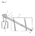
- FIG. 2 is a view for explaining operations of the thermosiphon 1.
- the heat-absorbing section formed on the distal end portion of the Stirling cooler 4 is cooled off.
- the condensing member 2 fixed on the distal end portion of the Stirling cooler 4 is cooled off.
- the condensing member 2 is cooled off, the portions of the pipe 3 held by the blocks 2a, 2b and configuring the condensing member 2 are cooled off.
- the pipe 3 is cooled off, the refrigerant filled therein is condensed.
- the condensed refrigerant flows each path 3a, 3b obliquely extending downward.
- the liquefied refrigerant which are flowing each path 3a, 3b absorbs a heat of the container 5 and evaporates while reaching the lowest portion 3c of the paths 3a, 3b, and the remaining of the liquefied refrigerant not evaporated is collected at the lowest portion 3c of the paths 3a, 3b.
- the refrigerant evaporated in the path 3a or 3b does not travel to other path 3b or 3a, but inversely drifts up the path 3a or 3b (the path in which the refrigerant evaporated) and returns to the condensing member 2.
- the refrigerant returned to the condensing member 2 is condensed again.
- the container 5 is cooled by repeating the above-described processes.
- the pipe 3 comprises: the path 3a extending along a half-periphery defined by the front surface 5a of the container 5 and the right surface 5b thereof; and the path 3b extending along the other half-periphery defined by the rear surface 5c of the container 5 and the left surface 5d thereof, wherein both ends of the paths 3a and 3b extending along the half-peripheries of the container 5 is arranged as the lowest portion 3c, and thus the inclination of the pipe 3 can be a little lesser than twice as much as that of the conventional structure in which a single path is arranged around the container 5, when the shape of the container 5 is same.
- thermosiphon 1 since the condensing member 2 is configured that the refrigerant is filled in the pipe 3, the portions of the pipe 3 are held by the bottom block 2a provided on the heat-absorbing section of the Stirling cooler 4, and the upper block 2b, the easiness of assembling the thermosiphon 1 can be improved.
- the refrigerant can be entirely diffused across the pipe 3, and thus the filling of the refrigerant therein can be made easy; the refrigerant can be evenly diffused across the paths 3a and 3b, and thus the cooling performance of each path 3a, 3b can be essentially equal.
- the entire volume of the pipe 3 filling the refrigerant can be enlarged, and thus the control of the amount of the refrigerant so as to obtain a predetermined density of the filled refrigerant can be made easy. Therefore, accuracy of the amount of the refrigerant in the pipe 3 can be enhanced.
- FIG. 3 is for explaining a thermosiphon used in the second embodiment of the present invention.
- the same reference numbers will denote the same structure portions of a cooling box of the first embodiment, while detailed explanations thereof will be omitted.
- FIG. 3 shows the thermosiphon 10 of this embodiment.
- the thermosiphon 10 comprises a condensing member 11 for condensing a refrigerant, and a pipe 12 for absorbing a heat of the container 5.
- the condensing member 11 is configured by holding portions of the pipes 12 adjacent to upper end thereof with a bottom block 11a and an upper block 11b. Meanwhile, the condensing member 11 is one that the condensing member 2 of the first embodiment is modified so as to hold the pipe 12. Moreover, the pipe 12 is one that the pipe 3 of the first embodiment is doubled.
- a first path 12a and a second path 12b contact the front and right surfaces 5a and 5b as same as the path 3a of the first embodiment.
- a third path 12c and a fourth path 12d contact the left and rear surfaces 5d and 5c as same as the path 3b of the first embodiment.
- An inclination angle of the first path 12a is essentially same as that of the third path 12c, while the inclination angle of the second path 12b is essentially same as that of the fourth path 12d.
- the first path 12a and the third path 12c are integrally connected with each other so as to form a lowest portion 12e.
- the second path 12b and the fourth path 12d are integrally connected with each other so as to form a lowest portion 12f.
- the first path 12a and the fourth path 12d are integrally connected with each other on the upward of the condensing member 11.
- the second path 12b and the third path 12c are integrally connected with each other on the upward of the condensing member 11. Accordingly, four of the paths 12a, 12b, 12c and 12d form the single, annular pipe 12.
- An inlet 12g for filling the refrigerant R is formed on a portion of the first path 12a.
- thermosiphon 10 Assembling procedures of the thermosiphon 10 and operations thereof are basically same as those of the thermosiphon 1 of the first embodiment, thus omitting the detailed explanations thereof.
- the pipe 12 is doubly arranged around the condensing member 11 and the container 5, the efficiency of absorbing the heat of the container 5 can be improved compared to the first embodiment.
- the refrigerant can be entirely diffused across the pipe 12, and thus the filling of the refrigerant therein can be made easy; the refrigerant can be evenly diffused across the paths 12a-12d, and thus the cooling performance of each path 12a, 12b, 12c, 12d can be essentially equal.
- the entire volume of the pipe 12 filling the refrigerant can be enlarged, and thus the control of the amount of the refrigerant so as to obtain a predetermined density of the filled refrigerant can be made easy. Therefore, accuracy of the amount of the refrigerant in the pipe 12 can be enhanced.
- the inlet 3d may be provided on a portion of the path 3b along the periphery of the container 5 (third embodiment).
- the inlet 3d may be provided at this position, the outside of the container 5 including the inlet 3d can be covered with the non-illustrated thermal insulator. Accordingly, a portion of the pipe 3 not covered with the thermal insulator, that is, the portion of the pipe 3 which extends from the condensing member 2 and contacts the outside surface of the container 5 can be formed in a simple shape, and thus this portion can be easily covered with the other thermal insulator.
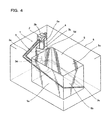
- the pipe 3 is formed in an annular shape in the above embodiments, but it may be in a shape that the lowest portion 3c is divided in two pieces as shown in FIG. 5 (fourth embodiment).
- the outside of the container 5 including the lowest portion 3c can be covered with the non-illustrated thermal insulator. Accordingly, a portion of the pipe 3 not covered with the thermal insulator, that is, the portion of the pipe 3 which extends from the condensing member 2 and contacts the outside surface of the container 5 can be formed in a simple shape, and thus this portion can be easily covered with the other thermal insulator. Further, as shown in FIG.
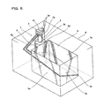
- a highest portion 3e of the pipe 3 provided upward of the condensing member 2 may be separated (fifth embodiment).
- the refrigerant can be filled after the pipe 3 is fixed on the periphery of the container 5 and covered with the thermal insulator, and thus the degree of freedom for the assembling order can be improved.
- the paths 3a and 3b are communicated with each other, the same effectiveness as that of the first embodiment can be obtained.
- the pipe 3 whilst the pipe 3 is doubly arranged around the container 5, but it may be arranged more than or equal to triply around the container 5.
Description
- The present invention relates to a cooling box comprising a Stirling cooler and a refrigerant-filled thermosiphon which comprises a condensing member provided on a heat-absorbing section of the Stirling cooler for condensing the refrigerant and a pipe connected to the condensing member and being arranged around a container of the cooling box so as to absorb a heat of the container.
- A conventional cooling box according to the preamble of claim 1 comprises a refrigerant-filled thermosiphon for absorbing heat of the container of a cooling box as shown in
JP-A-2003-148813 JP-A-2003-148813 JP-A-2003-148813 - In the above-described conventional technique, however, when a cooling box equipping the above thermosiphon tilts, the flow speed of the liquefied working fluid that circulates in the entire region of the evaporating pipe may be decreased, or the liquefied working fluid may not be circulated entirely, and thus an efficiency of absorbing the heat of the container on the evaporating pipe is lowered.
- As backround of the present invention, the article "Heat Pipes" by D. A. Reay (Phys. Technol., Vol. 16, No. 2, 1985, pages 69 to 75, XPO20047969 Bristol, GB) describes the general operation principle of thermosiphons and heat pipes. As further background of the present invention,
US 4,449,576 shows a heat pipe system comprising a plurality of heat pipes, each heat pipe being configured to cool a unit of stack of a plurality of units comprising PC-boards. - The present invention has been made to solve the problem described above with reference to the thermosiphon of the cooling box shown in
JP-A-2003-148813 - In order to attain the above object, a cooling box according to claim 1 is proposed according to the present invention. Preferred embodiments are described by the dependent claims.
- A refrigerant-filled thermosiphon (1, 10) comprises a condensing member (2, 11) for condensing the refrigerant (R), the condensing member (2, 11) being provided on a heat-absorbing section of a refrigerating machine (4); and a pipe (3, 12) connected to the condensing member (2, 11), the pipe (3, 12) being arranged around a container (5) so as to absorb a heat of the container (5), wherein: the pipe (3, 12) comprises a plurality of paths (3a, 3b, 12a, 12b, 12c, 12d), at least one of the paths (3a, 12a, 12c) being arranged so as to extend downwardly along a half-periphery of the container (5), while at least another of the paths (3b, 12b, 12d) being arranged so as to extend downwardly along another half-periphery of the container (5); and each path (3a, 3b, 12a, 12b, 12c, 12d) of the pipe (3, 12) is arranged so that a portion thereof going around a half-periphery of the container (5) along the container (5) defines a lowest portion (3c, 3e, 3f). Moreover, each path (3a, 3b, 12a, 12b, 12c, 12d) defines an individual path of the refrigerant (R), while all of the plurality of paths (3a, 3b, 12a, 12b, 12c, 12d) are communicated to one another so as to form the single pipe (3, 12),
- Accordingly, each path (3a, 3b, 12a, 12b, 12c, 12d) of the pipe (3, 12) is arranged so that a portion of each path (3a, 3b, 12a, 12b, 12c, 12d) going around a half-periphery of the container (5) along the container (5) defines a lowest portion (3c, 3e, 3f), thus enlarging the inclination angle of the pipe (3, 12) compared to one employing a conventional structure that one path extends around the container (5). Accordingly, the flow of the refrigerant (R) cannot be easily prevented even if a cooling box equipping this thermosiphon (1, 10) tilts, and thus likelihood to lower the efficiency of absorbing a heat of the container (5) can be reduced. Moreover, since at least one of the paths (3a, 12a, 12c) extends downwardly along the half-periphery of the container (5), while at least the other of the paths (3b, 12b, 12d) extends downwardly along the other half-periphery of the container (5), the cooling efficiency of the container (5) is not reduced even if each path (3a, 3b, 12a, 12b, 12c, 12d) is arranged so as to extend along the half-periphery of the container (5).
- Alternatively, in the above-described thermosiphon (1, 10), the condensing member (2, 11) may be configured that the refrigerant is filled in the pipe (3, 12) and a portion of the pipe (3, 12) is thermally contacted by at least one heat-conduction block (2a, 2b, 11a, 11b), the heat-conduction block (2a, 2b, 11a, 11b) being provided on a heat-absorbing section of the refrigerating machine (4).
- Further; the pipe (3, 12) may be arranged multiply around the condensing member (2, 11) and the container (5), while the pipe (3, 12) may be made of copper.
- Still further, the heat-conduction block (2a, 2b, 11a, 11b) may be made of aluminum.
-
FIG. 1 is a perspective view showing a structure of a cooling box according to a first embodiment of the present invention; -
FIG. 2 is a view for explaining operations of the thermosiphon shown inFIG. 1 ; -
FIG. 3 is a perspective view showing a structure of a cooling box according to a second embodiment of the present invention; -
FIG. 4 is a perspective view showing a structure of a cooling box according to a third embodiment of the present invention; -
FIG. 5 is a perspective view showing a structure of a cooling box according to a fourth embodiment of the present invention; and -
FIG. 6 is a perspective view showing a structure of a cooling box according to a fifth embodiment of the present invention. - Preferred embodiments of the present invention will now be described in detail with reference to the accompanying drawings.
FIGs. 1 and2 are for explaining a thermosiphon used in a first embodiment of the present invention. -
FIG. 1 is a perspective view showing the refrigerant-filled thermosiphon 1 of this embodiment. The thermosiphon 1 comprises acondensing member 2 for condensing a refrigerant R, and apipe 3 for absorbing a heat of a container. - The condensing
member 2 is fixed on a heat-absorbing section which is formed on a distal end portion of a Stirling cooler (refrigerating machine) 4. Meanwhile, since the Stirlingcooler 4 is well known by a person skilled in the art, detailed explanation thereof will be omitted in this specification. When the Stirlingcooler 4 is operated, the distal end portion thereof works as the heat-absorbing section, thus absorbing a heat conducted from the condensingmember 2. Moreover, the condensingmember 2 employs a structure that it holds portions of thepipe 3 adjacent to an upper end thereof with anbottom block 2a and anupper block 2b, each working as a heat-conduction block. Thebottom block 2a is fixed on the distal end portion of the Stirlingcooler 4. Meanwhile, the fixation of thebottom block 2a to the Stirlingcooler 4 can be carried out by, for instance, forming an opening on thebottom block 2a and pressing the distal end of the Stirlingcooler 4 into the opening of thebottom block 2a, or bonding it to the Stirlingcooler 4 with an adhesive of high heat-conductance. Moreover, the holding of thepipe 3 by the bottom andupper blocks bottom block 2a from an upper surface thereof and forming another hole for the screw on a portion of theupper block 2b corresponding to the hole of thebottom block 2a, then inserting the screw into the hole of theupper block 2b from the upper surface side thereof and tightening them up. The bottom andupper blocks - Overall, the
pipe 3 is formed in an annular shape. Two paths thereof are fixed on the condensingmember 2 so that they extend obliquely downward and parallel with each other until they reach the outside surfaces of thecontainer 5. Onepath 3a extends obliquely downward from thecondensing member 2. After reaching thecontainer 5, it extends while contacting afront surface 5a of thecontainer 5, curves at a boundary between thefront surface 5a and aright surface 5b so as to extend to theright surface 5b, and then reaches a boundary between theright surface 5b and arear surface 5c. Theother path 3b extends obliquely downward from the condensingmember 2. After reaching thecontainer 5, it extends while contacting aleft surface 5d, curves at a boundary between theleft surface 5d and therear surface 5c so as to extend to therear surface 5c, and then reaches a boundary between therear surface 5c and theright surface 5b. The onepath 3a and theother path 3b are integrally connected with each other at the boundary between theright surface 5b and therear surface 5c, while a portion in which bothpaths lowest portion 3c. Inclinations of the portions of bothpaths container 5 are essentially constant. Moreover, bothpaths member 2. Meanwhile, aninlet 3d for filling the refrigerant R is formed on the onepath 3a. Thepipe 3 is made of, for instance, a copper pipe of high heat-conductance. The refrigerant is filled in thepipe 3. Carbon dioxide, hydrochlorofluorocarbon (HCFC), hydrofluorocarbon (HFC) or the like can be used as the refrigerant. - By accommodating the thermosiphon 1, the Stirling
cooler 4 and thecontainer 5 in a case 6, a cooling box is to be composed. In the case 6, the outsides of the thermosiphon 1 andcontainer 5 are covered with a non-illustrated thermal insulator. - Explanation will now be made to assembling procedures of the thermosiphon 1 employing the above-described structure. First of all, one or more copper pipes are bent, while their ends are joined so as to form the
pipe 3 in a predetermined shape, that is, an annular shape shown inFIG. 1 , and then theinlet 3d is formed on a halfway portion of thepipe 3. The refrigerant is filled via theinlet 3d, and when the predetermined amount of the refrigerant is filled, theinlet 3d is sealed. Then, thepipe 3 is arranged so that the onepath 3a extends downwardly along thefront surface 5a of thecontainer 5 and theright surface 5b thereof, theother path 3b extends downwardly along theleft surface 5d of thecontainer 5 and therear surface 5c thereof, and the both ends of thepaths lowest portion 3c is arranged at the boundary between theright surface 5b and therear surface 5c. Moreover, each of thepaths container 5 is thermally contacted by thecontainer 5, while outside of thecontainer 5 with thepipe 3 is covered with the non-illustrated thermal insulator. Further, thecondensing member 2 is formed by holding the portions of thepipe 3 adjacent to the upper end thereof with thebottom block 2a prefixed on the Stirlingcooler 4 and theupper block 2b. Still further, a portion of thepipe 3 away from thecondensing member 2 and thecontainer 5 is covered with the non-illustrated thermal insulator. The above-described thermosiphon 1 is thus formed in this way. Meanwhile, in a procedure of filling the refrigerant in thepipe 3, since thepipe 3 has twopaths pipe 3 is equal to the sum of the volumes of thepaths pipe 3 so that the density of the refrigerant therein is to be a predetermined value, thereby improving the accuracy of the filling of the refrigerant. For instance, in a thermosiphon employing a conventional structure, in a case where an error of ±0.5g is to be observed for the amount of the filled refrigerant, the error relative to the single path formed by a pipe will be ±0.5g, and in a case filling the refrigerant in a plurality of paths, the error of ±0.5g can be observed relative to each path. According to the first embodiment, however, the error of ±0.5g can be entirely observed for thepipe 3 having twopaths path pipe 3 by the number ofpaths path - Next, operations of the thermosiphon 1 employing the above-described structure will now be described.
FIG. 2 is a view for explaining operations of the thermosiphon 1. As explained, when theStirling cooler 4 is operated, the heat-absorbing section formed on the distal end portion of theStirling cooler 4 is cooled off. When the heat-absorbing section of theStirling cooler 4 is cooled off, the condensingmember 2 fixed on the distal end portion of theStirling cooler 4 is cooled off. When the condensingmember 2 is cooled off, the portions of thepipe 3 held by theblocks member 2 are cooled off. When thepipe 3 is cooled off, the refrigerant filled therein is condensed. The condensed refrigerant flows eachpath path container 5 and evaporates while reaching thelowest portion 3c of thepaths lowest portion 3c of thepaths lowest portion 3c is filled with the liquefied refrigerant, the refrigerant evaporated in thepath other path path member 2. The refrigerant returned to the condensingmember 2 is condensed again. Thecontainer 5 is cooled by repeating the above-described processes. - As explained above, according to the first embodiment, the
pipe 3 comprises: thepath 3a extending along a half-periphery defined by thefront surface 5a of thecontainer 5 and theright surface 5b thereof; and thepath 3b extending along the other half-periphery defined by therear surface 5c of thecontainer 5 and theleft surface 5d thereof, wherein both ends of thepaths container 5 is arranged as thelowest portion 3c, and thus the inclination of thepipe 3 can be a little lesser than twice as much as that of the conventional structure in which a single path is arranged around thecontainer 5, when the shape of thecontainer 5 is same. Accordingly, the flow of the refrigerant would not be easily prevented even if a cooling box equipping the thermosiphon 1 tilts, thus reducing the lowering of the efficiency of absorbing the heat of thecontainer 5. Moreover, since bothpaths lowest portion 3c, the level of the liquefied refrigerant on eachpaths lowest portion 3c would be same, and thus the refrigerant can evenly circulate in bothpaths paths member 2, gas of the refrigerant can evenly circulate in bothpaths path 3a or theother path 3b. - Moreover, according to the first embodiment, since the condensing
member 2 is configured that the refrigerant is filled in thepipe 3, the portions of thepipe 3 are held by thebottom block 2a provided on the heat-absorbing section of theStirling cooler 4, and theupper block 2b, the easiness of assembling the thermosiphon 1 can be improved. - Further, according to the first embodiment, by filling the refrigerant from the
inlet 3d, the following effectiveness can be obtained: the refrigerant can be entirely diffused across thepipe 3, and thus the filling of the refrigerant therein can be made easy; the refrigerant can be evenly diffused across thepaths path pipe 3, the entire volume of thepipe 3 filling the refrigerant can be enlarged, and thus the control of the amount of the refrigerant so as to obtain a predetermined density of the filled refrigerant can be made easy. Therefore, accuracy of the amount of the refrigerant in thepipe 3 can be enhanced. - Next, a cooling box according to a second embodiment of the present invention will now be described.
FIG. 3 is for explaining a thermosiphon used in the second embodiment of the present invention. Meanwhile, in the second embodiment, the same reference numbers will denote the same structure portions of a cooling box of the first embodiment, while detailed explanations thereof will be omitted. -
FIG. 3 shows thethermosiphon 10 of this embodiment. Thethermosiphon 10 comprises a condensingmember 11 for condensing a refrigerant, and apipe 12 for absorbing a heat of thecontainer 5. - The condensing
member 11 is configured by holding portions of thepipes 12 adjacent to upper end thereof with abottom block 11a and anupper block 11b. Meanwhile, the condensingmember 11 is one that the condensingmember 2 of the first embodiment is modified so as to hold thepipe 12. Moreover, thepipe 12 is one that thepipe 3 of the first embodiment is doubled. - A
first path 12a and asecond path 12b contact the front andright surfaces path 3a of the first embodiment. Athird path 12c and afourth path 12d contact the left andrear surfaces path 3b of the first embodiment. An inclination angle of thefirst path 12a is essentially same as that of thethird path 12c, while the inclination angle of thesecond path 12b is essentially same as that of thefourth path 12d. On the boundary between theright surface 5b and therear surface 5c, thefirst path 12a and thethird path 12c are integrally connected with each other so as to form a lowest portion 12e. On the boundary between theright surface 5b and therear surface 5c, thesecond path 12b and thefourth path 12d are integrally connected with each other so as to form alowest portion 12f. Thefirst path 12a and thefourth path 12d are integrally connected with each other on the upward of the condensingmember 11. Thesecond path 12b and thethird path 12c are integrally connected with each other on the upward of the condensingmember 11. Accordingly, four of thepaths annular pipe 12. Aninlet 12g for filling the refrigerant R is formed on a portion of thefirst path 12a. - Assembling procedures of the
thermosiphon 10 and operations thereof are basically same as those of the thermosiphon 1 of the first embodiment, thus omitting the detailed explanations thereof. - According to the second embodiment, the
pipe 12 is doubly arranged around the condensingmember 11 and thecontainer 5, the efficiency of absorbing the heat of thecontainer 5 can be improved compared to the first embodiment. - Further, according to the second embodiment, by filling the refrigerant from the
inlet 12g, the following effectiveness can be obtained: the refrigerant can be entirely diffused across thepipe 12, and thus the filling of the refrigerant therein can be made easy; the refrigerant can be evenly diffused across thepaths 12a-12d, and thus the cooling performance of eachpath pipe 12, the entire volume of thepipe 12 filling the refrigerant can be enlarged, and thus the control of the amount of the refrigerant so as to obtain a predetermined density of the filled refrigerant can be made easy. Therefore, accuracy of the amount of the refrigerant in thepipe 12 can be enhanced. - The present invention is not limited to the above embodiments, various embodiments and changes may be made thereonto without departing from the scope of the invention. For instance, as shown in
FIG. 4 , theinlet 3d may be provided on a portion of thepath 3b along the periphery of the container 5 (third embodiment). By providing theinlet 3d at this position, the outside of thecontainer 5 including theinlet 3d can be covered with the non-illustrated thermal insulator. Accordingly, a portion of thepipe 3 not covered with the thermal insulator, that is, the portion of thepipe 3 which extends from the condensingmember 2 and contacts the outside surface of thecontainer 5 can be formed in a simple shape, and thus this portion can be easily covered with the other thermal insulator. Moreover, whilst thepipe 3 is formed in an annular shape in the above embodiments, but it may be in a shape that thelowest portion 3c is divided in two pieces as shown inFIG. 5 (fourth embodiment). By employing this structure, the outside of thecontainer 5 including thelowest portion 3c can be covered with the non-illustrated thermal insulator. Accordingly, a portion of thepipe 3 not covered with the thermal insulator, that is, the portion of thepipe 3 which extends from the condensingmember 2 and contacts the outside surface of thecontainer 5 can be formed in a simple shape, and thus this portion can be easily covered with the other thermal insulator. Further, as shown inFIG. 6 , ahighest portion 3e of thepipe 3 provided upward of the condensingmember 2 may be separated (fifth embodiment). By employing this structure, the refrigerant can be filled after thepipe 3 is fixed on the periphery of thecontainer 5 and covered with the thermal insulator, and thus the degree of freedom for the assembling order can be improved. Meanwhile, in all of those embodiments, since thepaths pipe 3 is doubly arranged around thecontainer 5, but it may be arranged more than or equal to triply around thecontainer 5.
Claims (5)
- A cooling box comprising a case (6) accomodating a Stirling cooler (4), a refrigerant-filled thermosiphon (1, 10) and a container (5), the cooling box further comprising:- a condensing member (2, 11) for condensing the refrigerant (R), said condensing member (2, 11) being provided on a heat-absorbing section of the stirling cooler (4);- a single pipe (3, 12) connected to said condensing member (2, 11), said pipe (3) being arranged around the container (5) so as to absorb heat of the container (5), said pipe (3, 12) comprising at least one first path (3a, 12a, 12b) and at least one second path (3b, 12c, 12d), wherein said first path (3a, 12a, 12b) and said second path (3b 12c, 12d) are communicated to one another so as to form the single pipe (3),said first path (3a, 12a, 12b) being fixed with a first end thereof to the condensing member (2, 11) and extending from said condensing member (2, 11) to said container (5) and along a half-periphery of said container (5) to a second end thereof which defines a lowest portion (3c, 12e, 12f) of said first path (3a, 12a, 12b), wherein said first path (3a, 12a, 12b) extends from its first end to its second end along its entire length obliquely downwards so as to allow condensed refrigerant to flow from said condensing member (2, 11) to said lowest portion (3c, 12e, 12f), andsaid second path (3b, 12c, 12d) extends along another half-periphery of said container (5) to a second end thereof which defines a lowest portion (3c, 12e, 12f) of said second path (3b, 12c, 12d), andsaid second path (3b, 12c, 12d) is fixed with a first end thereof to the condensing member (2, 11) and extends from said condensing member (2, 11) to said container (5), and refrigerant (R) evaporated in said second path (3b, 12c, 12d) drifts up said second path (3b, 12c, 12d) and returns to said condensing member (2, 11),
characterized in thatin said first path (3a, 12a, 12b) gaseous refrigerant (R), which is evaporated as the liquid refrigerant (R) flows downwards through said first path (3a 12a, 12b), drifts up said first path (3a, 12a, 12b) to said condensing member (2, 11),said second path (3b, 12c, 12d) extends from its first end to its second end along its entire length obliquely downwards so as to allow condensed refrigerant (R) to flow from said condensing member (2, 11) to said lowest portion (3c, 12e, 12f) of said second path (3b, 12c, 12d). - The cooling box according to claim 1, wherein said refrigerant is filled in said pipe (3, 12) and at least a portion of said pipe (3, 12) is thermally contacted by at least one heat-conduction block (2a, 2b, 11 a, 11 b) of said condensing member (2, 11), the heat-conduction block (2a, 2b, 11 a, 11 b) being provided on the heat-absorbing section of the Stirling cooler (4).
- The cooling box according to claim 2, wherein said pipe (3, 12) is arranged multiply around said condensing member (2, 11) and the container (5).
- The cooling box according to any one of claims 1 to 3, wherein said pipe (3, 12) is made of copper.
- The cooling box according to any one of claims 2 to 4, wherein said heat- conduction block (2a, 2b, 11a, 11b) is made of aluminum.
Applications Claiming Priority (2)
| Application Number | Priority Date | Filing Date | Title |
|---|---|---|---|
| JP2003394516A JP4277312B2 (en) | 2003-11-25 | 2003-11-25 | Thermosiphon |
| JP2003394516 | 2003-11-25 |
Publications (3)
| Publication Number | Publication Date |
|---|---|
| EP1536191A2 EP1536191A2 (en) | 2005-06-01 |
| EP1536191A3 EP1536191A3 (en) | 2006-09-27 |
| EP1536191B1 true EP1536191B1 (en) | 2010-05-12 |
Family
ID=34463784
Family Applications (1)
| Application Number | Title | Priority Date | Filing Date |
|---|---|---|---|
| EP04292485A Expired - Fee Related EP1536191B1 (en) | 2003-11-25 | 2004-10-19 | A cooling box comprising a Stirling cooler and a thermosiphon |
Country Status (4)
| Country | Link |
|---|---|
| US (1) | US7234319B2 (en) |
| EP (1) | EP1536191B1 (en) |
| JP (1) | JP4277312B2 (en) |
| DE (1) | DE602004027109D1 (en) |
Families Citing this family (12)
| Publication number | Priority date | Publication date | Assignee | Title |
|---|---|---|---|---|
| JPS6262314A (en) * | 1985-09-13 | 1987-03-19 | Hitachi Ltd | Large aperture reflecting mirror having temperature adjusting function |
| DE102009022074B4 (en) * | 2009-05-20 | 2011-01-27 | Siemens Aktiengesellschaft | Magnetic field generating device and associated manufacturing method |
| BR112012030204B1 (en) | 2010-05-27 | 2020-11-10 | Johnson Controls Technology Company | cooling system and method for operating the cooling system |
| US9587873B2 (en) | 2012-03-27 | 2017-03-07 | Global Cooling, Inc. | Energy efficient biological freezer with vial management system |
| WO2014173809A1 (en) * | 2013-04-24 | 2014-10-30 | Siemens Plc | An assembly comprising a two-stage cryogenic refrigerator and associated mounting arrangement |
| JP5986064B2 (en) * | 2013-12-25 | 2016-09-06 | Necプラットフォームズ株式会社 | Cooling system and electronic equipment |
| JP6224676B2 (en) * | 2015-11-12 | 2017-11-01 | 日本フリーザー株式会社 | Parallel and distributed cooling system |
| US10718558B2 (en) * | 2017-12-11 | 2020-07-21 | Global Cooling, Inc. | Independent auxiliary thermosiphon for inexpensively extending active cooling to additional freezer interior walls |
| CN111492191A (en) * | 2018-03-06 | 2020-08-04 | 普和希控股公司 | Refrigerating device |
| CN108444130A (en) * | 2018-04-09 | 2018-08-24 | 杨厚成 | A kind of cold end device of enhanced heat exchange |
| JP6934576B2 (en) * | 2018-09-11 | 2021-09-15 | Phcホールディングス株式会社 | Refrigeration equipment |
| JP7299017B2 (en) * | 2018-12-27 | 2023-06-27 | 川崎重工業株式会社 | Loop heat pipe and transportation |
Family Cites Families (12)
| Publication number | Priority date | Publication date | Assignee | Title |
|---|---|---|---|---|
| US2512545A (en) * | 1948-06-11 | 1950-06-20 | Frederick E Hazard | Structure for and method of transfer, exchange, control regulation, and storage of heat and cold |
| US2946206A (en) * | 1956-05-14 | 1960-07-26 | Electrolux Ab | Refrigerator employing secondary refrigeration system |
| US3880230A (en) * | 1973-06-01 | 1975-04-29 | Isothermics | Heat transfer system |
| DE3044314C2 (en) * | 1980-11-25 | 1986-08-14 | kabelmetal electro GmbH, 3000 Hannover | Housing for accommodating printed circuits equipped with heat-generating electronic components |
| DE3344046A1 (en) * | 1983-12-06 | 1985-06-20 | Brown, Boveri & Cie Ag, 6800 Mannheim | COOLING SYSTEM FOR INDIRECTLY COOLED SUPRALINE MAGNETS |
| US5884693A (en) * | 1997-12-31 | 1999-03-23 | Dsc Telecom L.P. | Integral heat pipe enclosure |
| JPH11211313A (en) * | 1998-01-26 | 1999-08-06 | Sanyo Electric Co Ltd | Refrigerator |
| JP3607837B2 (en) * | 1999-07-15 | 2005-01-05 | グローバル クーリング ビー ヴイ | refrigerator |
| JP2002013885A (en) * | 2000-06-28 | 2002-01-18 | Twinbird Corp | Thermo-siphon for refrigerator |
| JP3637593B2 (en) * | 2001-11-08 | 2005-04-13 | ツインバード工業株式会社 | Thermosiphon |
| JP2003214750A (en) * | 2002-01-23 | 2003-07-30 | Twinbird Corp | Thermosiphon |
| JP2005127550A (en) * | 2003-10-21 | 2005-05-19 | Twinbird Corp | Portable storage box |
-
2003
- 2003-11-25 JP JP2003394516A patent/JP4277312B2/en not_active Expired - Lifetime
-
2004
- 2004-10-19 EP EP04292485A patent/EP1536191B1/en not_active Expired - Fee Related
- 2004-10-19 US US10/968,622 patent/US7234319B2/en active Active
- 2004-10-19 DE DE602004027109T patent/DE602004027109D1/en active Active
Non-Patent Citations (1)
| Title |
|---|
| REAY D.A.: "HEAT PIPES", PHYSIC IN TECHNOLOGY, vol. 16, no. 2, 1 March 1985 (1985-03-01), BRISTOL, GB, pages 69 - 75, XP020047969 * |
Also Published As
| Publication number | Publication date |
|---|---|
| JP2005156011A (en) | 2005-06-16 |
| EP1536191A3 (en) | 2006-09-27 |
| JP4277312B2 (en) | 2009-06-10 |
| DE602004027109D1 (en) | 2010-06-24 |
| US7234319B2 (en) | 2007-06-26 |
| EP1536191A2 (en) | 2005-06-01 |
| US20050109057A1 (en) | 2005-05-26 |
Similar Documents
| Publication | Publication Date | Title |
|---|---|---|
| EP3232752B1 (en) | Cooling electronic devices in a data center | |
| EP1536191B1 (en) | A cooling box comprising a Stirling cooler and a thermosiphon | |
| US6360814B1 (en) | Cooling device boiling and condensing refrigerant | |
| RU2247912C2 (en) | Microcooling device | |
| JP3451737B2 (en) | Boiling cooling device | |
| US20070227703A1 (en) | Evaporatively cooled thermosiphon | |
| US4833567A (en) | Integral heat pipe module | |
| US7475718B2 (en) | Orientation insensitive multi chamber thermosiphon | |
| US20070246193A1 (en) | Orientation insensitive thermosiphon of v-configuration | |
| US7556089B2 (en) | Liquid cooled thermosiphon with condenser coil running in and out of liquid refrigerant | |
| US7650928B2 (en) | High performance compact thermosiphon with integrated boiler plate | |
| JP2007519877A (en) | Plate heat transfer device and manufacturing method thereof | |
| WO2018230349A1 (en) | Cooler and thermosyphon | |
| JPH0727999B2 (en) | Integrated heat pipe module | |
| US20240125561A1 (en) | Cooling device | |
| JP2005156011A5 (en) | ||
| JP2003247790A (en) | Boiling/cooling device | |
| JP5092931B2 (en) | Boiling cooler | |
| JP2004060911A (en) | Heat pipe | |
| MXPA06004692A (en) | Manufacture of a heat transfer system. | |
| JP2009068723A (en) | Absorption refrigerator | |
| JP2005308357A (en) | Thermosiphon | |
| JP3637593B2 (en) | Thermosiphon | |
| JP2000091482A (en) | Cooler for semiconductor element and manufacture thereof | |
| JP2021190479A (en) | Cooling system |
Legal Events
| Date | Code | Title | Description |
|---|---|---|---|
| PUAI | Public reference made under article 153(3) epc to a published international application that has entered the european phase |
Free format text: ORIGINAL CODE: 0009012 |
|
| AK | Designated contracting states |
Kind code of ref document: A2 Designated state(s): AT BE BG CH CY CZ DE DK EE ES FI FR GB GR HU IE IT LI LU MC NL PL PT RO SE SI SK TR |
|
| AX | Request for extension of the european patent |
Extension state: AL HR LT LV MK |
|
| PUAL | Search report despatched |
Free format text: ORIGINAL CODE: 0009013 |
|
| AK | Designated contracting states |
Kind code of ref document: A3 Designated state(s): AT BE BG CH CY CZ DE DK EE ES FI FR GB GR HU IE IT LI LU MC NL PL PT RO SE SI SK TR |
|
| AX | Request for extension of the european patent |
Extension state: AL HR LT LV MK |
|
| 17P | Request for examination filed |
Effective date: 20070223 |
|
| AKX | Designation fees paid |
Designated state(s): DE FR GB IT NL |
|
| 17Q | First examination report despatched |
Effective date: 20070521 |
|
| GRAP | Despatch of communication of intention to grant a patent |
Free format text: ORIGINAL CODE: EPIDOSNIGR1 |
|
| RTI1 | Title (correction) |
Free format text: A COOLING BOX COMPRISING A STIRLING COOLER AND A THERMOSIPHON |
|
| GRAS | Grant fee paid |
Free format text: ORIGINAL CODE: EPIDOSNIGR3 |
|
| GRAA | (expected) grant |
Free format text: ORIGINAL CODE: 0009210 |
|
| AK | Designated contracting states |
Kind code of ref document: B1 Designated state(s): DE FR GB IT NL |
|
| REG | Reference to a national code |
Ref country code: GB Ref legal event code: FG4D |
|
| REF | Corresponds to: |
Ref document number: 602004027109 Country of ref document: DE Date of ref document: 20100624 Kind code of ref document: P |
|
| REG | Reference to a national code |
Ref country code: NL Ref legal event code: T3 |
|
| PLBE | No opposition filed within time limit |
Free format text: ORIGINAL CODE: 0009261 |
|
| STAA | Information on the status of an ep patent application or granted ep patent |
Free format text: STATUS: NO OPPOSITION FILED WITHIN TIME LIMIT |
|
| 26N | No opposition filed |
Effective date: 20110215 |
|
| REG | Reference to a national code |
Ref country code: DE Ref legal event code: R097 Ref document number: 602004027109 Country of ref document: DE Effective date: 20110214 |
|
| PGFP | Annual fee paid to national office [announced via postgrant information from national office to epo] |
Ref country code: IT Payment date: 20121024 Year of fee payment: 9 |
|
| PG25 | Lapsed in a contracting state [announced via postgrant information from national office to epo] |
Ref country code: IT Free format text: LAPSE BECAUSE OF NON-PAYMENT OF DUE FEES Effective date: 20131019 |
|
| REG | Reference to a national code |
Ref country code: FR Ref legal event code: PLFP Year of fee payment: 12 |
|
| REG | Reference to a national code |
Ref country code: FR Ref legal event code: PLFP Year of fee payment: 13 |
|
| PGFP | Annual fee paid to national office [announced via postgrant information from national office to epo] |
Ref country code: DE Payment date: 20161020 Year of fee payment: 13 Ref country code: GB Payment date: 20161020 Year of fee payment: 13 Ref country code: NL Payment date: 20161019 Year of fee payment: 13 Ref country code: FR Payment date: 20161020 Year of fee payment: 13 |
|
| REG | Reference to a national code |
Ref country code: DE Ref legal event code: R119 Ref document number: 602004027109 Country of ref document: DE |
|
| REG | Reference to a national code |
Ref country code: NL Ref legal event code: MM Effective date: 20171101 |
|
| GBPC | Gb: european patent ceased through non-payment of renewal fee |
Effective date: 20171019 |
|
| REG | Reference to a national code |
Ref country code: FR Ref legal event code: ST Effective date: 20180629 |
|
| PG25 | Lapsed in a contracting state [announced via postgrant information from national office to epo] |
Ref country code: NL Free format text: LAPSE BECAUSE OF NON-PAYMENT OF DUE FEES Effective date: 20171101 Ref country code: GB Free format text: LAPSE BECAUSE OF NON-PAYMENT OF DUE FEES Effective date: 20171019 Ref country code: DE Free format text: LAPSE BECAUSE OF NON-PAYMENT OF DUE FEES Effective date: 20180501 |
|
| PG25 | Lapsed in a contracting state [announced via postgrant information from national office to epo] |
Ref country code: FR Free format text: LAPSE BECAUSE OF NON-PAYMENT OF DUE FEES Effective date: 20171031 |