EP1536337A2 - Remote copy network - Google Patents
Remote copy network Download PDFInfo
- Publication number
- EP1536337A2 EP1536337A2 EP04012936A EP04012936A EP1536337A2 EP 1536337 A2 EP1536337 A2 EP 1536337A2 EP 04012936 A EP04012936 A EP 04012936A EP 04012936 A EP04012936 A EP 04012936A EP 1536337 A2 EP1536337 A2 EP 1536337A2
- Authority
- EP
- European Patent Office
- Prior art keywords
- information
- storage
- identification information
- volume
- edge device
- Prior art date
- Legal status (The legal status is an assumption and is not a legal conclusion. Google has not performed a legal analysis and makes no representation as to the accuracy of the status listed.)
- Granted
Links
Images


Classifications
-
- H—ELECTRICITY
- H04—ELECTRIC COMMUNICATION TECHNIQUE
- H04L—TRANSMISSION OF DIGITAL INFORMATION, e.g. TELEGRAPHIC COMMUNICATION
- H04L67/00—Network arrangements or protocols for supporting network services or applications
- H04L67/01—Protocols
- H04L67/10—Protocols in which an application is distributed across nodes in the network
- H04L67/1097—Protocols in which an application is distributed across nodes in the network for distributed storage of data in networks, e.g. transport arrangements for network file system [NFS], storage area networks [SAN] or network attached storage [NAS]
-
- G—PHYSICS
- G06—COMPUTING; CALCULATING OR COUNTING
- G06F—ELECTRIC DIGITAL DATA PROCESSING
- G06F11/00—Error detection; Error correction; Monitoring
- G06F11/07—Responding to the occurrence of a fault, e.g. fault tolerance
- G06F11/16—Error detection or correction of the data by redundancy in hardware
- G06F11/20—Error detection or correction of the data by redundancy in hardware using active fault-masking, e.g. by switching out faulty elements or by switching in spare elements
- G06F11/2053—Error detection or correction of the data by redundancy in hardware using active fault-masking, e.g. by switching out faulty elements or by switching in spare elements where persistent mass storage functionality or persistent mass storage control functionality is redundant
- G06F11/2056—Error detection or correction of the data by redundancy in hardware using active fault-masking, e.g. by switching out faulty elements or by switching in spare elements where persistent mass storage functionality or persistent mass storage control functionality is redundant by mirroring
- G06F11/2069—Management of state, configuration or failover
-
- G—PHYSICS
- G06—COMPUTING; CALCULATING OR COUNTING
- G06F—ELECTRIC DIGITAL DATA PROCESSING
- G06F11/00—Error detection; Error correction; Monitoring
- G06F11/07—Responding to the occurrence of a fault, e.g. fault tolerance
- G06F11/16—Error detection or correction of the data by redundancy in hardware
- G06F11/20—Error detection or correction of the data by redundancy in hardware using active fault-masking, e.g. by switching out faulty elements or by switching in spare elements
- G06F11/2053—Error detection or correction of the data by redundancy in hardware using active fault-masking, e.g. by switching out faulty elements or by switching in spare elements where persistent mass storage functionality or persistent mass storage control functionality is redundant
- G06F11/2056—Error detection or correction of the data by redundancy in hardware using active fault-masking, e.g. by switching out faulty elements or by switching in spare elements where persistent mass storage functionality or persistent mass storage control functionality is redundant by mirroring
- G06F11/2071—Error detection or correction of the data by redundancy in hardware using active fault-masking, e.g. by switching out faulty elements or by switching in spare elements where persistent mass storage functionality or persistent mass storage control functionality is redundant by mirroring using a plurality of controllers
- G06F11/2074—Asynchronous techniques
-
- G—PHYSICS
- G06—COMPUTING; CALCULATING OR COUNTING
- G06F—ELECTRIC DIGITAL DATA PROCESSING
- G06F11/00—Error detection; Error correction; Monitoring
- G06F11/07—Responding to the occurrence of a fault, e.g. fault tolerance
- G06F11/16—Error detection or correction of the data by redundancy in hardware
- G06F11/20—Error detection or correction of the data by redundancy in hardware using active fault-masking, e.g. by switching out faulty elements or by switching in spare elements
- G06F11/2053—Error detection or correction of the data by redundancy in hardware using active fault-masking, e.g. by switching out faulty elements or by switching in spare elements where persistent mass storage functionality or persistent mass storage control functionality is redundant
- G06F11/2056—Error detection or correction of the data by redundancy in hardware using active fault-masking, e.g. by switching out faulty elements or by switching in spare elements where persistent mass storage functionality or persistent mass storage control functionality is redundant by mirroring
- G06F11/2082—Data synchronisation
-
- G—PHYSICS
- G06—COMPUTING; CALCULATING OR COUNTING
- G06F—ELECTRIC DIGITAL DATA PROCESSING
- G06F11/00—Error detection; Error correction; Monitoring
- G06F11/07—Responding to the occurrence of a fault, e.g. fault tolerance
- G06F11/16—Error detection or correction of the data by redundancy in hardware
- G06F11/20—Error detection or correction of the data by redundancy in hardware using active fault-masking, e.g. by switching out faulty elements or by switching in spare elements
- G06F11/2053—Error detection or correction of the data by redundancy in hardware using active fault-masking, e.g. by switching out faulty elements or by switching in spare elements where persistent mass storage functionality or persistent mass storage control functionality is redundant
- G06F11/2056—Error detection or correction of the data by redundancy in hardware using active fault-masking, e.g. by switching out faulty elements or by switching in spare elements where persistent mass storage functionality or persistent mass storage control functionality is redundant by mirroring
- G06F11/2066—Optimisation of the communication load
-
- G—PHYSICS
- G06—COMPUTING; CALCULATING OR COUNTING
- G06F—ELECTRIC DIGITAL DATA PROCESSING
- G06F11/00—Error detection; Error correction; Monitoring
- G06F11/07—Responding to the occurrence of a fault, e.g. fault tolerance
- G06F11/16—Error detection or correction of the data by redundancy in hardware
- G06F11/20—Error detection or correction of the data by redundancy in hardware using active fault-masking, e.g. by switching out faulty elements or by switching in spare elements
- G06F11/2053—Error detection or correction of the data by redundancy in hardware using active fault-masking, e.g. by switching out faulty elements or by switching in spare elements where persistent mass storage functionality or persistent mass storage control functionality is redundant
- G06F11/2056—Error detection or correction of the data by redundancy in hardware using active fault-masking, e.g. by switching out faulty elements or by switching in spare elements where persistent mass storage functionality or persistent mass storage control functionality is redundant by mirroring
- G06F11/2071—Error detection or correction of the data by redundancy in hardware using active fault-masking, e.g. by switching out faulty elements or by switching in spare elements where persistent mass storage functionality or persistent mass storage control functionality is redundant by mirroring using a plurality of controllers
- G06F11/2076—Synchronous techniques
-
- H—ELECTRICITY
- H04—ELECTRIC COMMUNICATION TECHNIQUE
- H04L—TRANSMISSION OF DIGITAL INFORMATION, e.g. TELEGRAPHIC COMMUNICATION
- H04L67/00—Network arrangements or protocols for supporting network services or applications
- H04L67/01—Protocols
- H04L67/10—Protocols in which an application is distributed across nodes in the network
- H04L67/1095—Replication or mirroring of data, e.g. scheduling or transport for data synchronisation between network nodes
Definitions
- This invention relates to an information processing system comprising storage device, and more specifically, to remote copying and disaster recovery technology, executed by a remote copy network (hereafter also called an "RCN") comprising two or more storage devices and two or more network devices.
- RCN remote copy network
- remote copying When failure occurs in a storage device of an information processing system due to electrical power failure, natural disasters or other disasters, operations using the information processing system are halted temporarily, and in the worst case, data stored in the storage device may be lost.
- remote copying there exists technology (hereafter called "remote copying") through which data stored in storage devices of the information storage system is transferred to and copied in storage devices prepared at a remote location different from the information processing system.
- synchronous remote copying when there is a write request from a computer of the information storage system, after completion of the transfer of data accompanying the write request to a storage device existing at the remote location, a storage device of the information processing system sends a response to the write request to the computer.
- synchronous remote copying there is little data loss due to failures, but increased communication line delays between storage devices result in worsened I/O performance between computers and storage devices.
- JP-A-2003-122509 and JP-A-2000-305856 assume that the owner of the storage devices manages intermediate devices, increases in the costs of device ownership and in management costs are problems.
- a multi-hop remote copy technology is here disclosed which can suppress increases in the costs of device ownership and in management costs.
- Remote copying is executed via a remote copy network (RCN) having source edge devices connected to source storage and target edge devices connected to target storage.
- RCN remote copy network
- a source edge device receives a remote copy I/O request from source storage, creates a log entry to which a sequential number is assigned, and sends the log entry to a target edge device.
- the target edge device acquires the remote copy I/O request from the received log entry, and sends, in the order of sequential numbers, remote copy I/O requests to the target storage.
- Fig. 1 shows a general example of an information processing system in one aspect of this invention.
- the information processing system comprises a remote copy network 101, wide-area network 102, management server 103, management network 150, host computer (hereafter simply "host") 111 and host 121, external storage 112, and external storage 122.
- the external storage 112 may, as storage having a copy source volume 113 for remote copying, be called source external storage 112
- the external storage 122 may, as storage having a copy destination volume 123, be called target external storage 122.
- source and target are used to express the relations between the host 111 and host 121, volume 113 and volume 123, virtual storage 106 and virtual storage 107, and virtual volume 108 and virtual volume 109. These relations are not fixed, and a certain external storage device may serve as both source and target.
- the remote copy network 101, wide-area network 102, management network 150, and management server 103 are provided by a network business.
- a customer having a source-side host and source external storage, and a target-side host and target external storage can connect the hosts and external storage devices to a remote copy network to execute remote copying via the remote copy network. Consequently a customer can execute multi-hop remote copying without managing or maintaining a remote copy network, so that the device ownership costs and management costs of multi-hop remote copying can be reduced.
- the host 111 and host 121 are computers on which application programs to perform transaction processing and other operations run; the volume 113 is a volume used by host 111, and the volume 123 is a volume used by host 121.
- the remote copy network 101 is a network comprising edge devices 104 and 105, the core device 202, and a plurality of other devices.
- the core device 202 is not essential device for the remote copy network 101.
- Edge devices and core devices may be a type of router or gateway device.
- the external storage 112 and external storage 122 are connected via the edge device 104 or edge device 105 to the remote copy network 101.
- remote copy requests and data for remote copying accompanying remote copy requests hereafter called either "remote copy I/O requests" or "RIO"
- RIO remote copy I/O requests
- Processing to convert an RIO into a log entry is executed by the edge device.
- An edge device is a device which is connected to external storage existing outside the remote copy network 101.
- a core device 202 is a device which transfers log entries 211, created and transferred by an edge device 104, to another edge device 105 or to a core device 202.
- Virtual storage 106 or 107 is virtual storage which is provided by the edge device 104 or the edge device 105, to external storage 112 or 122.
- An edge device provides, to the external storage to which it is connected, virtual storage which behaves as opposite side external storage paired for remote copying, to display itself as opposite side external storage paired with the external storage for remote copying (for example, the edge device 104 provides to the external storage 112 virtual storage 106 which behaves as the external storage 122; the edge device 105 provides to the external storage 122 virtual storage 107 which behaves as the external storage 112).
- Edge devices and core devices 202 are connected by a network not shown.
- the IP protocol on Gigabit Ethernet (a registered trademark; hereafter also called “GbE”) is possible, but other network media and protocols may also be used.
- GbE the IP protocol on Gigabit Ethernet
- protocols such as SCSI, iSCSI, iFCP, mFCP, FCIP or similar on Fiber Channel (hereafter also called "FC"), ESCON, FICON, GbE or similar are possible; but other protocols on other network media may also be used.
- FC and SCSI are used to connect edge devices to external storage
- GbE and the IP protocol and UDP protocol are used to connect edge devices and core devices 202; however, the scope of this invention is not limited to these protocols.
- An FC frame 220 is a frame for communication between external storage and edge devices via FC;
- a GbE frame 210 is a frame for communication between edge devices and core devices, or between a plurality of core devices, via GbE; and log entries 211 are transferred using GbE frames 210.
- the management server 103 is a computer to configure information needed by the owner (customer) of the external storage 112 and external storage 122 to use the remote copy network and to reference the configuration and state information of the remote copy network 101, and is connected to the wide-area network 102 and management network 150.
- the host 111 and host 121 use the wide-area network 102 to communicate with the management server 103.
- the wide-area network 102 may take any form so long as communication between the hosts 111 and 121 and the management server 103 is possible, and may be comprised in the remote copy network 101.
- a plurality of external storage devices may be connected to a single edge device.
- the management network 150 connects the devices existing within the remote copy network 101 (for example, the edge devices 104 and 105, and the core devices 202) with the management server 103.
- the management server configures edge devices and core devices within the remote copy network 101 via the management network 150, collects information from edge devices and core devices, and provides collected information to hosts via the wide-area network 102.
- the management network 150 may be one portion of the remote copy network 101, or may be one portion of the wide-area network 103.
- the external storage 112 and external storage 122 have memory which stores a synchronous remote copy program or an asynchronous remote copy program, and a processor which executes the program.
- the external storage defines the pair state (there are five states, which are Simplex (X), Initial-Copying (IC), Duplex (D), Suspend (S), and Duplex-Pending (DP)) in order to indicate the copy state, and manages this information internally.
- X Simplex
- IC Initial-Copying
- D Duplex
- S Suspend
- DP Duplex-Pending
- the Simplex state is a state in which synchronous remote copying between a source volume and a target volume has not been initiated.
- the Duplex state is a state in which synchronous remote copying has been initiated, the initialization copying described below has also been completed, and the contents of the source volume and target volume are identical.
- this copying may also be called "update copying"
- a writing-completed response is returned to the host which had performed the writing.
- the Initial-Copying state is an intermediate state in the transition from the Simplex state to the Duplex state. During this period, initialization copying (copying of data already stored in the source volume) from the source volume to the target volume is performed. When initialization copying is completed and the internal processing necessary for the transition to the Duplex state has ended, the pair state becomes Duplex.
- the Suspend state is a stated in which update copying is halted. In this state, the macroscopic data identity between the source volume and target volume is no longer guaranteed.
- the pair state Upon an instruction from an operator, a host, or a computer managing external storage, the pair state makes a transition from another state to the Suspend state.
- failure Suspend state there is a transition to the Suspend state ,when it may not be possible to perform synchronous remote copying from the source volume to the target volume. In such cases the storage automatically makes a transition to the Suspend state. In the following explanation, the latter case is called a "failure Suspend state".
- Representative causes of such a failure Suspend state are failures in the source volume or target volume, failures in the source external storage or the target external storage, and failure in the communication channel between source external storage and target external storage (in the case of this aspect, network failure between the external storage 112 or 122 and the edge device 104 or 105, or failure of the remote copy network comprising the edge devices 104 and 105). However, failures other than these can also cause a failure Suspend state.
- External storage in the Suspend state or the failure Suspend state records the storage area in the volume in which is stored data updated while in the Suspend state or the failure Suspend state, so as to enable execution of differential copying (copying only updated area) between source volume and target volume upon a transition of the pair state to the Duplex-Pending state.
- the data structure used in recording may be a bitmap (herein named differential bitmap) or log structure, but other structures may be used.
- the Duplex-Pending state is an intermediate state in the transition from the Suspend state to the Duplex state. In this state, in order to cause the data of the source volume and target volume to identical, copying of data from source volume to target volume is executed. When identity between the data of the source volume and target volume is secured, the pair state becomes Duplex. Copying of data while in the Duplex-Pending state may utilize information recorded in the data update area while in the Suspend state, described above, to perform differential copying in which only the portion requiring updating is copied. Moreover, the Initial-Copying state and Duplex-Pending state may be combined into a single state and displayed on the screen of a management device, or transitions between these states may be performed.
- the following method is one method of copying data from the source volume to the target volume.
- the source external storage creates a set (hereafter called a "log entry") of written data and control information comprising the address of the volume to which the data has been written, and transfers this to the target external storage, and the target external storage writes to the target volume the updated data stored in the log entry (hereafter, writing of data stored in a log entry to a volume is called "reflecting the log entry in the volume").
- a log entry a set of written data and control information comprising the address of the volume to which the data has been written
- information indicating the time and order of writing of the updated data to the source volume is comprised in the control information of a log entry, and when reflecting a log entry in a target volume, this information indicating the time and order is utilized to reflect the log entry in the target volume in the order in which the updated data was written to the source volume.
- the source and target external storage manage the pair state (Simplex, Initial-Copying, Duplex, Suspend, Duplex-Pending, and Suspending (SI)).
- the Simplex, Initial-Copying, Suspend, and Duplex-Pending states are similar to those for synchronous remote copying.
- the Duplex state also is essentially the same as for synchronous remote copying, but because update copying is performed asynchronously with writing from the host, means of data identity differs from that of synchronous remote copying. For the instance, after the host receives a completion response for a write request from the source external storage, the data in the source volume and the data in the target volume are not exactly equal until the updated data is written to the target volume.
- the Suspending state is an intermediate state in a transition from the Duplex state to the Suspend state; in the case of asynchronous remote copying, transitions are made to the Suspend state via the Suspending state.
- the source external storage and target external storage may perform processing to reflect, in the target external storage, log entries held in the memory of source and target external storages.
- a method similar to the recording of the write position in the source volume described in the explanation of the Suspend state for synchronous remote copying is used by the source external storage and target external storage to record the write position of updated data in log entries which could not be reflected in the target volume.
- Fig. 9 is a flow diagram showing one example of remote copy processing utilizing a remote copy network.
- Fig. 3 shows one example of the hardware architecture of an edge device, core device, and management server.
- Each of these devices has memory 311, a CPU 312, and a disk device 313, which are interconnected via an internal network or a bus. Programs existing in each device are stored in the memory 311, and programs are executed through the concerted operation of the memory 311, CPU 312, and disk device 313. However, the disk device 313 is not an essential component.
- the edge device and core device each have a GbE interface 315, which is hardware for communication over GbE.
- the edge device has an FC interface 314 for communication by FC with external storage.
- the edge device, core device, and management server each have a network interface 316 to communicate using the management network 150.
- the network interface 316 may be the same as the FC interface 314 or GbE interface 315, but any interface enabling communication and supporting other network media and protocols, such as a 100BaseT Ethernet interface, may be used.
- Fig. 4 shows one example of a program within the memory 311 or disk device 313 of an edge device or core device, and which runs on the edge device or core device.
- the FC protocol stack 401 is a program which is executed by an edge device to perform data transfer via the FC.
- the IP protocol stack 410 is a program which is executed by an edge device or by a core device 202 to perform data transfer via the GbE according to the IP.
- An interface driver program to manipulate the GbE interface 315 or FC interface 314, PortID and WWN conversion information present in the FC protocol stack 401, and IP address and MAC (Media Access Control) address conversion information present in the IP protocol stack 410 exist within the memory 311 of the edge device, but are not shown in the figure.
- an OS also not shown, may exist in an edge device and core device.
- the RIO protocol stack 402 is a program enabling an edge device to interpret a RIO received from external storage, and is present in an edge device.
- the virtual storage provision program 403 is a program to provide virtual storage, behaving as some external storage, to external storage connected the edge device, and is present in the edge device.
- virtual storage which behaves like opposite side external storage paired for remote copying with the connected-external storage device
- the storage device information that is, the WWN, product number, number of volumes, LUNs to identify volumes, capacity, emulation type, and similar
- the opposite side external storage device paired for remote copying with the connected-external storage device is provided to the connected-external storage as the storage device information of the virtual storage.
- the virtual storage provision program 403 provides to the connected-external storage, storage device information specific to the virtual storage rather than storage device information of the opposite side external storage device.
- the log entry creation/reflection program 406 is a program to create a log entry 211 based on a RIO transferred to virtual storage 106 acquired from the external storage provision program 403, RIO protocol stack 401, and FC protocol stack 401, and is present in the edge device.
- the RIO protocol stack 402, virtual storage provision program 403, and log entry creation/reflection program 406 run on the edge devices 106 and 107.
- the log entry transfer program 407 is a program to use the log communication protocol stack 409 and IP protocol stack 410 to transfer log entries 211, and is present in edge devices and core devices.
- the log transfer protocol stack 409 is a program to perform communication processing necessary for the transfer of log entries 211 between other edge devices or core devices.
- the log entry transfer program 407 and log transfer protocol stack 409 run on the edge devices 106, 107 and core devices 202.
- the batch transfer program 420 is a program which controls the log entry transfer program 407 running on a core device in order to efficiency perform transfer of log entries 211.
- the batch transfer program is present in the core device.
- the batch transfer program 420 waits a fixed length of time from receipt of a log entry 211 until transfer, and when transferring log entries, transfers a plurality of log entries 211 accumulated in the core device 202 in a batch.
- a batch transfer program 420 may not be used.
- Fig. 5 shows one example of a program stored in the memory of the management server 103 and running on the management server 103, as well as information stored in the memory of the management server.
- the RCN configuration interface program 501 is a program which performs configuration in order to execute remote copy processing between a plurality of external storage devices using the remote copy network 101.
- the RCN configuration interface program 501 is also a program which outputs to enable user referencing of remote copy network configuration information, storage connection information 503, virtual storage information 404, access control information 405, routing information 408, and pair information 411.
- Hosts or other computers connected to the wide-area network 102 can use this program, stored in the management server, to reference the state of the remote copy network 101 and perform configuration corresponding to step 903 in Fig. 9 (that is, configuration of the edge devices and core devices comprised in the RCN).
- the following two types of information are examples of information configured using the RCN configuration interface program 501; but by inputting configuration information for the RCN configuration interface program running on the management server, the customer or a manager can make other configurations as well.
- Information provided by the RCN configuration interface program 501 may comprise, in addition to the above two configuration values, the following items; but the RCN configuration interface program may output items other than these as well.
- the RCN configuration interface program 501 may also perform processing to limit input values for selection of edge devices, the number of external storage devices connected to the RCN, the number of volume pairs for which the order is assured, and similar, based on the contract conditions.
- this limitation may be execute due to another reason.
- the RCN configuration program 502 comprises the following two functions.
- the RCN configuration program 502 may also comprise functions to collect and configure information from the remote copy network 101 and from edge devices and core devices 202.
- the memory of the management server also stores storage connection information 503, virtual storage information 404, access control information 405, routing information 408, and pair information 411, described below.
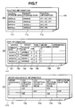
- Fig. 6 and Fig. 7 show examples of information used by the management server 103, edge devices, and core devices.
- the storage connection information 503 is information to manage the connection state of external storage with edge devices. This information comprises the IDs 631 of edge devices, customer IDs 632, and the WWNs 633 of external storage connected to edge devices. This information may be configured by the customer in the management server using the RCN configuration interface program 501, but other methods of creation may be used as well.
- the virtual storage information 404 is information relating to virtual storage provided by edge devices.
- a virtual storage WWN 612 is an area for registration of the WWN of virtual storage provided by an edge device to external storage.
- the corresponding edge ID 613 and corresponding storage WWN 614 indicates the external storage location behaved by the virtual storage having WWN 612. Therefore, ID 613 is area for registration of the ID of the edge device connected to the behaved external storage.
- WWN 613 is area for registration of the WWN of the behaved external storage.
- the WWN of the virtual storage 106 the WWN of the external storage 122 is assigned, and as the WWN of the virtual storage 107, the WWN of the external storage 112 is assigned.
- Fig. 1 as an example, the following values are registered in the virtual storage information 404.
- the identification numbers (LUNs) of the target volume and virtual target volume provided by virtual storage 106 are assumed to be the same values in this aspect.
- LUNs of the source volume and virtual source volume provided by virtual storage 107 are assumed to be the same value in this aspect, too.
- the access control information 405 is information to manage control of access to virtual storage provided by edge devices. This information comprises the edge device ID 621, virtual storage WWN 622, and the WWN 623 of the external storage which permits accessing of the virtual storage. Because an edge device may be shared by a plurality of customers, the access control information 405 is generally configured such that the virtual storage of one customer cannot be accessed from the external storage of another customer. However, configuration policies other than this may be adopted. Also, an edge device may perform access control using information other than this.
- the access control information 405 is created by the management server based on the storage connection information 503 and virtual storage information 404.
- the virtual storage 106 and virtual storage 107 cannot be used from the other customer's external storage(not shown in Fig. 1) connected to the edge device 104 or the edge device 105.
- the routing information 408 is information to manage the route for transfer of a log entry 211 created by a source-side edge device 104 to a target-side edge device 105.
- This information comprises the WWN 711 of the source external storage 112, the WWN 712 of the target external storage 122, and the transit route 714 for sending and receiving log entries 211 between the source external storage and target external storage.
- the RCN configuration program 502 Upon input to a management server 103 by the customer of identification information for the source external storage and target external storage, as well as of identification information for the source-side edge device and target-side edge device to which these external storage devices are connected, the RCN configuration program 502 calculates a route and creates routing information 408 such that the number of core devices 202 between the source external storage 104 and target external storage 105 is small, taking into consideration the processing limits of each core device 202 and the effectiveness of batch transfers. The method of deciding on a route may take into account the QoS of data transfer and the possibility of disaster at an edge device or core device 202 in calculations, but other methods may be used as well. Further, the routing information 408 in this embodiment assumes a case in which routes are configured for each pair of source external storage and target external storage; but routing information may be configured in units of order assurance groups, or in units of pairs of source volumes and target volumes.
- the pair information 411 is information to manage, mainly in the remote copy network 101, group of remote-copy pair of source volumes and target volumes for which the RIO order is to be assured.
- This information comprises the actual WWN 721 of the source external storage 112 and the LUN 722 of the source volume 113, the actual WWN 723 of the target external storage 122 and LUN 724 of the target volume 123, the current pair state 725, an ID 726 for order assurance, and a differential bitmap 727 for use when a failure occurs within the remote copy network 101.
- a method which combines these methods may also be used.
- the order assurance information 413 is primarily information to create sequential numbers 804 for log entries 211.
- This information comprises an order assurance ID 731, log creation counter value 732, log reflection counter value 733, log deletion counter value 734, and reflection delay time 735.
- the log creation counter value 732 is incremented by the edge device 104 each time a log entry 211 is created, and the log deletion counter value 734 is incremented by the edge device 104 each time a log entry 211 is deleted.
- the log reflection counter value 733 is incremented by the edge device 105 each time a log entry 211 is reflected in external storage 122.
- each time edge device 105 reflects a log entry to external storage 122. This information is periodically sent from edge device 105 to the RCN configuration interface program 501 of the management server 103, and is provided to the customer by being output from management server 103.
- log entries 211 are also stored in edge devices.
- Log entries 211 are stored in the log storage area 413 shown in Fig. 15, and the log storage area 413 comprises an area 1702 storing one or more log entries 211 and management information 1701 to manage the storing place.
- the log entry creation/reflection program 406 acquires information in the log storage area 413 in response to a request from the RCN configuration interface program 501, and provides this to the RCN configuration interface program.
- Copies of the virtual storage information 404, access control information 405, and pair information 411 exist in the edge device. Also, a copy of the routing information 408 exists in edge devices and core devices 202. Copies may be partial copies.
- Fig. 8 is a schematic diagram showing an example of the data structure of a log entry 211.
- the "WWN of target storage and volume LUN information” 801 is information indicating the WWN and LUN of external storage which is the transfer destination of a RIO converted into a log entry 211.
- the "source storage WWN and volume LUN information” 802 is information indicating the WWN and LUN of external storage which is the transfer source of a RIO converted into a log entry 211.
- the order assurance ID 803 and "I/O time and sequential number information" 804 are information to convey the reflection order between log entries 211. That is, the I/O time is the time at which write data comprised in a log entry from a host to the source external storage was written, and the sequential number is a number indicating the order of writing of write data from the host to the source external storage.
- the RIO area 805 is an area for storing a RIO which is to be converted into a log entry.
- a log entry 211 may comprise information other than the above as well.
- Fig. 14 shows examples of an FC frame 220 and GbE frame 210.
- the FC frame 220 comprises a transfer source PortID 1411, transfer destination PortID 1412, RIO area 1414, and other header information 1413.
- the RIO area comprises RIOs for transfer.
- the GbE frame comprises a transfer source IP address 1421, transfer destination IP address 1422, log entry area 1424, and other header information 1423.
- the log entry area comprises log entries for transfer.
- a RIO or log entry may be divided into a plurality of frames and sent, for example, in order to transfer a RIO or log entry of size exceeding the maximum frame size.
- Fig. 10 and Fig. 11 are flowcharts showing examples of system operation from the issuing of an instruction for pair creation in step 904 of Fig. 9, until initialization copying is performed and the pair state makes the transition to Duplex.
- step 903 of Fig. 9 it is assumed that configuration by the RCN configuration interface program 501 and updating of the storage connection information 503, virtual storage information 404, access control information 405, routing information 408, and pair information 411 by the RCN configuration program 502 have been completed. It is also assumed that edge devices and core devices 202 have provided virtual storage, initiated access control, and initialized order assurance information 413 based on the above information.
- Fig. 16 is a timeline showing one example of command transfer processing (that is, write processing during normal operation) when there is data writing to the source external storage system from a host in an information processing system.
- FC and IP (UDP, TCP) level Acknowledge messages are omitted.
- the above example is a case of routing which passes once through the core device 202; when there is no core device 202, the transfer processing by the core device 202 may be omitted, and when there is a plurality of core devices 202, transfer processing between core devices 202 may be added.
- the target-side edge device 105 or core device 202 loses a log entry (WR) due to failure or for some other reason, the log entry (WR) held by the source-side edge device 104 is resent.
- the source-side edge device 104 does not receive the log entry (WROK) within a stipulated time, resending is executed.
- the edge device 104 and edge device 105 instruct the external storage 112 and external storage 122 to make a transition to the failure Suspend state.
- the source-side edge device 104 converts the log entry (RW) held in the log storage area into a differential bitmap 27 of the pair information 411 and holds this bitmap.
- Fig. 12 shows one example of resynchronization processing from the Suspend state or from the failure Suspend state.
- Fig. 13 is a flow diagram showing an example of operation of the target-side host 121, target external storage 122, and target-side edge device 105 when disaster occurs at the source-side site during normal operation and failover occurs at the target-side host.
- the processing shown in Fig. 13 corresponds to step 911 in Fig. 9.
- the steps 1310, 1311, 1312 may be executed to promptly execute the transition to the failure Suspend state after step 1303.
- the target external storage 105 sends the RIO (SOK)
- log entries 211 remains in the remote copy network 101.
- the RCN configuration interface program 501 is used to acquire remaining log entries from the RCN, to resolve this problem. If, after completion of the transition to failure Suspend, the target external storage 122 does not receive a RIO (WR) to reflect in the target volume 123 the write data held as log entries by the RCN, this write data may be reflected using a SCSI command (WR).
- WR SCSI command
- Fig. 19 is a flow diagram showing an example of processing of the source-side edge device 104 when writing (WR) to the source volume 113 is performed during normal operation.
- Fig. 20 is a flow diagram showing an example of processing of the target-side edge device 105 when writing (WR) from a host to a source volume 113 is performed during normal operation.
- Fig. 17 and Fig. 18 show an example of processing by the source-side edge device 104 in pair creation.
- Fig. 21 and Fig. 22 show an example of processing by a target-side edge device 105 during pair creation.
- remote copy processing can be executed by relaying data from the source external storage to the target external storage using edge devices and core devices within the RCN, without the source external storage or target external storage being made aware of the existence of edge devices or core devices, but as if recognizing that remote copy processing is being executed directly between the storage devices.
- Fig. 2 shows an example of an information processing system of the modified example.
- Differences with the first embodiment are the fact that the WWN of the virtual storage 106 differs from the WWN of the external storage 122, and the fact that the WWN of the virtual storage 107 differs from the WWN of the external storage 112.
- the RCN configuration program 502 of the management server 103 in addition to the operations in the above aspect, also determines the WWNs of the virtual storage 106 and the virtual storage 107. The determination may be performed within this program, or the values may be determined by receiving information from the edge device 104 or the edge device 105.
- the RCN configuration interface program 501 in addition to the operations in the above aspect, also sends the WWN of the virtual storage 106 determined by the RCN configuration program 502 to the host 111 and the WWN of the virtual storage 107 determined by the RCN configuration program 502 to the host 121.
- the WWN of the source external storage and LUN of the source volume and the WWN of the virtual storage 106 and LUN of the virtual volume 108 (the LUN of the virtual volume 108 is taken to be the same as the LUN of the target volume 123; however, this invention is not limited to the present example) are used, when the host 111 sends a SCSI command for the volume pair of the source volume 113 and target volume 123.
- the virtual storage provision program 403 of the edge device in addition to the operations in the above aspect, also performs the following conversions using the virtual storage information 404 when a RIO is transmitted or received.
- connection of the external storage and edge device can be performed using an IP network.
- the FC interface 314 is an interface which can be connected with the IP network, and the FC protocol stack 401 becomes the same as the IP protocol stack 410.
- a MAC address or IP address is used in place of the WWN in the following information.
Abstract
Description
Claims (20)
- A remote copy network system, coupled to a first storage system and a second storage system, and comprising:a first edge device coupled to said first storage system;a second edge device coupled to said second storage system; anda network coupled to said first edge device and to said second edge device, wherein:said first edge device receives a remote copy I/O request to copy data to said second storage system from said first storage system;said first edge device sends a response to the received remote copy I/O request to said first storage system;after sending a response to the remote copy I/O request, said first edge device sends to said second edge device log information having the remote copy I/O request and a sequential number indicating the order of reception of the remote copy I/O request; andsaid second edge device extracts the remote copy I/O request from the received log information, and sends the extracted remote copy I/O request to said second storage system according to the order indicated by the sequential number in the log information.
- The system of Claim 1, wherein:said first storage system comprises a first volume, said first storage system is identified by first storage identification information and said first volume is identified by first volume identification information;said second storage system comprises a second volume, said second storage system is identified by second storage identification information and said second volume is identified by second volume identification information;first virtual storage identification information having the same value as said second storage identification information and second virtual volume identification information having the same value as said second volume identification information are assigned to said first edge device;second virtual storage identification information having the same value as said first storage identification information and second virtual volume identification information having the same value as said first volume identification information are assigned to said second edge device; andsaid first edge device receives a remote copy I/O request from said first storage system, with said first storage identification information and said first volume identification information as the sending source identification information and with said second storage identification information and said second volume identification information as the sending destination identification information, and sends log information having the remote copy I/O request to said second edge device.
- The system of Claim 1, wherein:said first storage system comprises a first volume, said first storage system is identified by first storage identification information and said first volume is identified by first volume identification information;said second storage system comprises a second volume, said second storage system is identified by second storage identification information and said second volume is identified by second volume identification information;first virtual storage identification information and first virtual volume identification information are assigned to said first edge device; andsaid first edge device receives a remote copy I/O request from said first storage system, with said first storage identification information and said first volume identification information as the sending source identification information and with said first virtual storage identification information and said first virtual volume identification information as the sending destination identification information, converts the sending destination into said second storage identification information and said second volume information, and sends log information having the converted I/O request to said second edge device.
- The system of Claim 1, further comprising at least one core device which relays log information sent from said first edge device to said second edge device.
- The system of Claim 4, wherein said first edge device, said second edge device, and said core device are router devices.
- The system of Claim 1, wherein said first edge device stores log information sent to said second edge device, and upon receiving a response to said log information from said second edge device, deletes said stored log information.
- The system of Claim 6, wherein, when log information sent to said second edge device is not received by said second edge device, said first edge device resends stored log information to said second edge device.
- The system of Claim 6, further comprising:a management network coupled to said first edge device and to said second edge device; anda management server coupled to said management network, wherein:log information further comprises information indicating the time at which the remote copy I/O request from said first edge device was received;said first edge device, upon receiving a response to said log information from said second edge device, records in memory the delay time calculated by subtracting the value of the time information comprised in the log information corresponding to the response from the current time;said first edge device sends said delay time recorded in said memory to said management server via said management network; andsaid management server outputs said delay time.
- The system of Claim 1, further comprising:a third edge device coupled to a fourth storage system, wherein:said first edge device is further connected to a third storage system;said first edge device receives a remote copy I/O request for remote copying data from said third storage system to said fourth storage system; andsaid first edge device distinguishes a remote copy I/O request received from said first storage system and a remote copy I/O request received from said third storage system to perform processing.
- The system of Claim 1, further comprising:a management network coupled to said first edge device and to said second edge device; anda management server coupled to said management network, and wherein:said management server receives pair information indicating that said first storage system is a source of remote copying and that said second storage system is a remote copying destination corresponding to said first storage system, and distributes the received pair information, via said management network, to said first edge device and to said second edge device.
- A relay device, coupled to a first storage system and which relays remote copy of data from the first storage system to a second storage system, comprising:a first interface coupled to said first storage system;a second interface coupled to another relay device via a network, wherein said other relay device is coupled to said second storage system;a processor; and,memory, wherein:said first interface portion receives a remote copy I/O request for remote copying data from said first storage system to said second storage system, and returns a response to the remote copy I/O request to said first storage system;said processor creates and stores in said memory log information having a remote copy I/O request and a sequential number indicating the order of reception of the remote copy I/O request;said second interface portion, after returning a response to the remote copy I/O request, sends the created log information to said other relay device;said second interface portion receives a response to the log information; andsaid processor deletes from said memory the log information corresponding to the received response.
- The relay device of Claim 11, wherein, when said second interface portion does not receive a response to the log information, said second interface portion resends the log information stored in said memory.
- The relay device of Claim 11, further comprising a third interface coupled to a management server via a network, wherein:said log information further comprises information indicating the time at which said first interface portion received the remote copy I/O request; andwhen said second interface portion receives a response to the log information,said processor calculates the delay time by subtracting the time information comprised in the log information corresponding to said response from the time at which said response was received; andsaid third interface portion sends the delay time to said management server.
- The relay device of Claim 11, further comprising a third interface coupled to a management server, wherein:first virtual storage identification information and first virtual volume information are assigned to the relay device; andsaid third interface portion receives, from said management server, pair information taking said first virtual storage identification information and said first virtual volume information to be the sending destination information for remote copying, and taking the first storage identification information which is said first storage system identification information and the first volume identification information which is the first volume identification information of said first storage system to be the sending source information for remote copying.
- The relay device of Claim 14, wherein:said first virtual storage identification information has the same value as the second storage identification information, which is the identification information of said second storage device system; andsaid first virtual volume information has the same value as the second volume identification information, which is the identification information of the second volume of said second storage device system.
- The relay device of Claim 14, wherein:a remote copy I/O request received by said first interface portion comprises said first storage identification information and said first volume identification information as the sending source information, as well as said first virtual storage information and said first virtual volume information as the sending destination information; andsaid processor converts the information of the sending destination to the second storage identification information which is the identification information of said second storage system, and converts the second volume identification information which is the identification information of the second volume of said second storage system, and creates log information having the converted remote #copy I/O request.
- A relay device, coupled to a second storage system, wherein said relay device relays remote copy of data from a first storage system to the second storage system, comprising:a first interface portion, coupled to another relay device via a network, wherein said other relay device is coupled to said first storage system;a second interface, coupled to said second storage system; anda processor, and whereinsaid first interface portion receives, from said other relay device, log information having a remote copy I/O request for remote copying data from said first storage system to said second storage system and a sequential number indicating the order of reception at said other relay device of the remote copy I/O request;said processor acquires the remote copy I/O request from the received log information; and,said second interface portion sends the acquired remote copy I/O request, in the order of the sequential number comprised in the log information, to said second storage system.
- The relay device of Claim 17, further comprising a third interface coupled to a management server, wherein:second virtual storage identification information and second virtual volume information are assigned to the relay device; andsaid third interface portion receives, from said management server, pair information taking said second virtual storage identification information and said second virtual volume information to be the sending source information for remote copying, and taking the second storage identification information which is the identification information of said second storage system and second volume identification information which is the identification information of the second volume of said second storage system to be the sending destination information for remote copying.
- The relay device of Claim 18, wherein:said second virtual storage identification information has the same value as the first storage identification information which is the identification information of said first storage system; andsaid second virtual volume identification information has the same value as the first volume identification information which is the identification information of the first volume of said first storage system.
- The relay device of Claim 18, wherein:the remote copy I/O request within log information received by said first interface comprises said first storage identification information and said first volume identification information as the sending source information and said second storage information and said second volume information as the sending destination information;said processor acquires the remote copy I/O request within the received log information and converts the sending source information into said second virtual storage identification information and said second virtual volume identification information; and,said second interface portion sends the converted remote copy I/O request to said second storage system.
Applications Claiming Priority (2)
| Application Number | Priority Date | Filing Date | Title |
|---|---|---|---|
| JP2003394921 | 2003-11-26 | ||
| JP2003394921A JP2005157712A (en) | 2003-11-26 | 2003-11-26 | Remote copy network |
Publications (3)
| Publication Number | Publication Date |
|---|---|
| EP1536337A2 true EP1536337A2 (en) | 2005-06-01 |
| EP1536337A3 EP1536337A3 (en) | 2006-05-03 |
| EP1536337B1 EP1536337B1 (en) | 2008-03-05 |
Family
ID=34463789
Family Applications (1)
| Application Number | Title | Priority Date | Filing Date |
|---|---|---|---|
| EP04012936A Expired - Fee Related EP1536337B1 (en) | 2003-11-26 | 2004-06-01 | Remote copy network |
Country Status (5)
| Country | Link |
|---|---|
| US (3) | US7055011B2 (en) |
| EP (1) | EP1536337B1 (en) |
| JP (1) | JP2005157712A (en) |
| CN (2) | CN101426025B (en) |
| DE (1) | DE602004012220T2 (en) |
Families Citing this family (22)
| Publication number | Priority date | Publication date | Assignee | Title |
|---|---|---|---|---|
| WO2005101241A2 (en) * | 2004-04-13 | 2005-10-27 | Alon Tavori | Method for depositing and retrieving digital records |
| JP2006293850A (en) * | 2005-04-13 | 2006-10-26 | Hitachi Ltd | Remote copy system and remote copy method |
| JP4920391B2 (en) * | 2006-01-06 | 2012-04-18 | 株式会社日立製作所 | Computer system management method, management server, computer system and program |
| US7890611B2 (en) * | 2006-01-12 | 2011-02-15 | Comcast Cable Holdings, Llc | Edge QAM device configuration using a configuration file having a dynamic file format |
| US20070300026A1 (en) * | 2006-06-23 | 2007-12-27 | Kwok-Yan Leung | Synchronous backup device and method used for storage device |
| KR100843136B1 (en) * | 2006-11-14 | 2008-07-02 | 삼성전자주식회사 | Apparatus and method for controlling operation processing in non volatile memory |
| JP2008299481A (en) * | 2007-05-30 | 2008-12-11 | Hitachi Ltd | Storage system and data copy method between several base points |
| US8271706B2 (en) * | 2008-05-22 | 2012-09-18 | International Business Machines Corporation | Stabilization of host to storage subsystem ownership |
| US20100050021A1 (en) * | 2008-08-25 | 2010-02-25 | International Business Machines Corporation | Error code handling in a storage subsystem |
| JP2010097533A (en) * | 2008-10-20 | 2010-04-30 | Hitachi Ltd | Application migration and power consumption optimization in partitioned computer system |
| JP5617304B2 (en) * | 2010-03-26 | 2014-11-05 | 富士通株式会社 | Switching device, information processing device, and fault notification control program |
| US9183560B2 (en) | 2010-05-28 | 2015-11-10 | Daniel H. Abelow | Reality alternate |
| CN103546514B (en) * | 2012-07-13 | 2016-12-21 | 阿里巴巴集团控股有限公司 | A kind of method and system processing the daily record data postponing transmission |
| CN104838367A (en) * | 2013-03-14 | 2015-08-12 | 株式会社日立制作所 | Method and apparatus of disaster recovery virtualization |
| JP6489144B2 (en) * | 2017-03-23 | 2019-03-27 | 日本電気株式会社 | Information processing device |
| CN108063685B (en) * | 2017-12-06 | 2021-06-18 | 迈普通信技术股份有限公司 | Log analysis method and device |
| US10691568B2 (en) * | 2018-07-26 | 2020-06-23 | International Business Machines Corporation | Container replication and failover orchestration in distributed computing environments |
| JP7150585B2 (en) | 2018-12-06 | 2022-10-11 | エヌ・ティ・ティ・コミュニケーションズ株式会社 | Data retrieval device, its data retrieval method and program, edge server and its program |
| JP7175731B2 (en) * | 2018-12-06 | 2022-11-21 | エヌ・ティ・ティ・コミュニケーションズ株式会社 | Storage management device, method and program |
| JP7150584B2 (en) | 2018-12-06 | 2022-10-11 | エヌ・ティ・ティ・コミュニケーションズ株式会社 | Edge server and its program |
| CN110418218B (en) * | 2019-07-26 | 2021-06-29 | 新华三技术有限公司成都分公司 | Message processing method and device and FCF switching equipment |
| CN111158612B (en) * | 2020-04-02 | 2020-07-24 | 中国人民解放军国防科技大学 | Edge storage acceleration method, device and equipment for cooperative mobile equipment |
Citations (4)
| Publication number | Priority date | Publication date | Assignee | Title |
|---|---|---|---|---|
| WO1994000816A1 (en) * | 1992-06-18 | 1994-01-06 | Andor Systems, Inc. | Remote dual copy of data in computer systems |
| US5960216A (en) * | 1993-04-23 | 1999-09-28 | Emc Corporation | Method and apparatus for interfacing two remotely disposed devices coupled via a transmission medium |
| US20030172316A1 (en) * | 2002-03-06 | 2003-09-11 | Tremblay Glenn A. | Producing a mirrored copy using incremental-divergence |
| EP1357476A2 (en) * | 2002-04-26 | 2003-10-29 | Hitachi, Ltd. | Method for controlling storage system, and storage control apparatus |
Family Cites Families (31)
| Publication number | Priority date | Publication date | Assignee | Title |
|---|---|---|---|---|
| US5327144A (en) | 1993-05-07 | 1994-07-05 | Associated Rt, Inc. | Cellular telephone location system |
| KR0128271B1 (en) * | 1994-02-22 | 1998-04-15 | 윌리암 티. 엘리스 | Remote data duplexing |
| US5537533A (en) * | 1994-08-11 | 1996-07-16 | Miralink Corporation | System and method for remote mirroring of digital data from a primary network server to a remote network server |
| US5889935A (en) * | 1996-05-28 | 1999-03-30 | Emc Corporation | Disaster control features for remote data mirroring |
| JP3835569B2 (en) * | 1996-12-20 | 2006-10-18 | ヤマハマリン株式会社 | Outboard motor |
| US5949970A (en) * | 1997-01-07 | 1999-09-07 | Unisys Corporation | Dual XPCS for disaster recovery |
| US5937414A (en) * | 1997-02-28 | 1999-08-10 | Oracle Corporation | Method and apparatus for providing database system replication in a mixed propagation environment |
| US6073209A (en) | 1997-03-31 | 2000-06-06 | Ark Research Corporation | Data storage controller providing multiple hosts with access to multiple storage subsystems |
| US6324654B1 (en) * | 1998-03-30 | 2001-11-27 | Legato Systems, Inc. | Computer network remote data mirroring system |
| JP2968790B1 (en) | 1998-08-25 | 1999-11-02 | 茨城日本電気株式会社 | Address conversion method for magnetic disk drive, magnetic disk drive, recording medium recording address conversion program |
| JP4689137B2 (en) | 2001-08-08 | 2011-05-25 | 株式会社日立製作所 | Remote copy control method and storage system |
| US6477543B1 (en) * | 1998-10-23 | 2002-11-05 | International Business Machines Corporation | Method, apparatus and program storage device for a client and adaptive synchronization and transformation server |
| US6209002B1 (en) * | 1999-02-17 | 2001-03-27 | Emc Corporation | Method and apparatus for cascading data through redundant data storage units |
| JP2000305856A (en) | 1999-04-26 | 2000-11-02 | Hitachi Ltd | Disk subsystems and integration system for them |
| US6539462B1 (en) * | 1999-07-12 | 2003-03-25 | Hitachi Data Systems Corporation | Remote data copy using a prospective suspend command |
| US7203732B2 (en) * | 1999-11-11 | 2007-04-10 | Miralink Corporation | Flexible remote data mirroring |
| TW536672B (en) * | 2000-01-12 | 2003-06-11 | Hitachi Ltd | IC card and microcomputer |
| US6658540B1 (en) * | 2000-03-31 | 2003-12-02 | Hewlett-Packard Development Company, L.P. | Method for transaction command ordering in a remote data replication system |
| US6601187B1 (en) * | 2000-03-31 | 2003-07-29 | Hewlett-Packard Development Company, L. P. | System for data replication using redundant pairs of storage controllers, fibre channel fabrics and links therebetween |
| JP2001306414A (en) | 2000-04-25 | 2001-11-02 | Hitachi Ltd | Remote copying system for storage device |
| US6383482B1 (en) * | 2000-08-24 | 2002-05-07 | Vitacost.Com, Inc. | Weight loss composition containing green tea, hydroxycitric acid, 5-hydroxytryptophan, glucomannan, picolinate and lactobacillus |
| US6665812B1 (en) * | 2000-12-22 | 2003-12-16 | Emc Corporation | Storage array network backup configuration |
| US6701392B1 (en) | 2001-11-14 | 2004-03-02 | Emc Corporation | Hierarchical approach to indentifying changing device characteristics |
| US6976139B2 (en) | 2001-11-14 | 2005-12-13 | Emc Corporation | Reversing a communication path between storage devices |
| JP2003316616A (en) | 2002-04-24 | 2003-11-07 | Hitachi Ltd | Computer system |
| US7134044B2 (en) * | 2002-08-16 | 2006-11-07 | International Business Machines Corporation | Method, system, and program for providing a mirror copy of data |
| US7024528B2 (en) * | 2002-08-21 | 2006-04-04 | Emc Corporation | Storage automated replication processing |
| JP4393762B2 (en) * | 2002-12-19 | 2010-01-06 | 株式会社日立製作所 | Database processing method and apparatus and processing program therefor |
| US7065589B2 (en) * | 2003-06-23 | 2006-06-20 | Hitachi, Ltd. | Three data center remote copy system with journaling |
| US7188222B2 (en) * | 2003-09-29 | 2007-03-06 | International Business Machines Corporation | Method, system, and program for mirroring data among storage sites |
| US7412576B2 (en) * | 2004-12-08 | 2008-08-12 | Hitachi, Ltd. | Remote copy system having multiple data centers |
-
2003
- 2003-11-26 JP JP2003394921A patent/JP2005157712A/en active Pending
-
2004
- 2004-03-31 US US10/816,572 patent/US7055011B2/en not_active Expired - Fee Related
- 2004-06-01 DE DE602004012220T patent/DE602004012220T2/en active Active
- 2004-06-01 EP EP04012936A patent/EP1536337B1/en not_active Expired - Fee Related
- 2004-11-26 CN CN2008101869288A patent/CN101426025B/en active Active
- 2004-11-26 CN CNB2004100961062A patent/CN100456256C/en not_active Expired - Fee Related
-
2006
- 2006-02-14 US US11/354,671 patent/US7305531B2/en not_active Expired - Fee Related
-
2007
- 2007-11-06 US US11/935,780 patent/US7809909B2/en not_active Expired - Fee Related
Patent Citations (4)
| Publication number | Priority date | Publication date | Assignee | Title |
|---|---|---|---|---|
| WO1994000816A1 (en) * | 1992-06-18 | 1994-01-06 | Andor Systems, Inc. | Remote dual copy of data in computer systems |
| US5960216A (en) * | 1993-04-23 | 1999-09-28 | Emc Corporation | Method and apparatus for interfacing two remotely disposed devices coupled via a transmission medium |
| US20030172316A1 (en) * | 2002-03-06 | 2003-09-11 | Tremblay Glenn A. | Producing a mirrored copy using incremental-divergence |
| EP1357476A2 (en) * | 2002-04-26 | 2003-10-29 | Hitachi, Ltd. | Method for controlling storage system, and storage control apparatus |
Also Published As
| Publication number | Publication date |
|---|---|
| CN100456256C (en) | 2009-01-28 |
| US20060168146A1 (en) | 2006-07-27 |
| US20050114730A1 (en) | 2005-05-26 |
| US7055011B2 (en) | 2006-05-30 |
| US7305531B2 (en) | 2007-12-04 |
| DE602004012220T2 (en) | 2009-03-19 |
| CN101426025B (en) | 2013-02-13 |
| CN101426025A (en) | 2009-05-06 |
| US7809909B2 (en) | 2010-10-05 |
| JP2005157712A (en) | 2005-06-16 |
| CN1637714A (en) | 2005-07-13 |
| US20080065848A1 (en) | 2008-03-13 |
| EP1536337A3 (en) | 2006-05-03 |
| DE602004012220D1 (en) | 2008-04-17 |
| EP1536337B1 (en) | 2008-03-05 |
Similar Documents
| Publication | Publication Date | Title |
|---|---|---|
| US7809909B2 (en) | Remote copy network | |
| JP4282464B2 (en) | Remote copy system | |
| JP4236049B2 (en) | Method, system, and program for providing a mirror copy of data | |
| US7130974B2 (en) | Multi-site remote-copy system | |
| US7412576B2 (en) | Remote copy system having multiple data centers | |
| US6345368B1 (en) | Fault-tolerant access to storage arrays using active and quiescent storage controllers | |
| US7600087B2 (en) | Distributed remote copy system | |
| US7472173B2 (en) | Remote data copying among storage systems | |
| US8285824B2 (en) | Storage system and data replication method that refuses one or more requests for changing the first logical configuration information until the first storage apparatus and second storage apparatus are synchronized | |
| US8468314B2 (en) | Storage system, storage apparatus, and remote copy method for storage apparatus in middle of plural storage apparatuses | |
| US20140351365A1 (en) | Management server and data migration method | |
| US20070239933A1 (en) | Volume providing system and method | |
| US7987154B2 (en) | System, a method and a device for updating a data set through a communication network | |
| US20090240975A1 (en) | Method and apparatus for virtual network attached storage remote migration | |
| JP2005309793A (en) | Data processing system | |
| US7167962B2 (en) | Remote copy for a storage controller with reduced data size | |
| JP4080970B2 (en) | Switch that provides path switching | |
| JP2007048323A (en) | Virtualization controller and data migration control method | |
| US8583884B2 (en) | Computing system and backup method |
Legal Events
| Date | Code | Title | Description |
|---|---|---|---|
| PUAI | Public reference made under article 153(3) epc to a published international application that has entered the european phase |
Free format text: ORIGINAL CODE: 0009012 |
|
| AK | Designated contracting states |
Kind code of ref document: A2 Designated state(s): AT BE BG CH CY CZ DE DK EE ES FI FR GB GR HU IE IT LI LU MC NL PL PT RO SE SI SK TR |
|
| AX | Request for extension of the european patent |
Extension state: AL HR LT LV MK |
|
| PUAL | Search report despatched |
Free format text: ORIGINAL CODE: 0009013 |
|
| AK | Designated contracting states |
Kind code of ref document: A3 Designated state(s): AT BE BG CH CY CZ DE DK EE ES FI FR GB GR HU IE IT LI LU MC NL PL PT RO SE SI SK TR |
|
| AX | Request for extension of the european patent |
Extension state: AL HR LT LV MK |
|
| 17P | Request for examination filed |
Effective date: 20060331 |
|
| 17Q | First examination report despatched |
Effective date: 20060620 |
|
| AKX | Designation fees paid |
Designated state(s): DE FR GB IE |
|
| 17Q | First examination report despatched |
Effective date: 20060620 |
|
| GRAP | Despatch of communication of intention to grant a patent |
Free format text: ORIGINAL CODE: EPIDOSNIGR1 |
|
| GRAS | Grant fee paid |
Free format text: ORIGINAL CODE: EPIDOSNIGR3 |
|
| GRAA | (expected) grant |
Free format text: ORIGINAL CODE: 0009210 |
|
| AK | Designated contracting states |
Kind code of ref document: B1 Designated state(s): DE FR GB IE |
|
| REG | Reference to a national code |
Ref country code: GB Ref legal event code: FG4D |
|
| REG | Reference to a national code |
Ref country code: IE Ref legal event code: FG4D |
|
| REF | Corresponds to: |
Ref document number: 602004012220 Country of ref document: DE Date of ref document: 20080417 Kind code of ref document: P |
|
| ET | Fr: translation filed | ||
| PLBE | No opposition filed within time limit |
Free format text: ORIGINAL CODE: 0009261 |
|
| STAA | Information on the status of an ep patent application or granted ep patent |
Free format text: STATUS: NO OPPOSITION FILED WITHIN TIME LIMIT |
|
| 26N | No opposition filed |
Effective date: 20081208 |
|
| PGFP | Annual fee paid to national office [announced via postgrant information from national office to epo] |
Ref country code: IE Payment date: 20090424 Year of fee payment: 6 |
|
| PGFP | Annual fee paid to national office [announced via postgrant information from national office to epo] |
Ref country code: FR Payment date: 20090429 Year of fee payment: 6 |
|
| REG | Reference to a national code |
Ref country code: FR Ref legal event code: ST Effective date: 20110228 |
|
| PG25 | Lapsed in a contracting state [announced via postgrant information from national office to epo] |
Ref country code: IE Free format text: LAPSE BECAUSE OF NON-PAYMENT OF DUE FEES Effective date: 20100601 |
|
| PG25 | Lapsed in a contracting state [announced via postgrant information from national office to epo] |
Ref country code: FR Free format text: LAPSE BECAUSE OF NON-PAYMENT OF DUE FEES Effective date: 20100630 |
|
| PGFP | Annual fee paid to national office [announced via postgrant information from national office to epo] |
Ref country code: GB Payment date: 20150527 Year of fee payment: 12 Ref country code: DE Payment date: 20150527 Year of fee payment: 12 |
|
| REG | Reference to a national code |
Ref country code: DE Ref legal event code: R119 Ref document number: 602004012220 Country of ref document: DE |
|
| GBPC | Gb: european patent ceased through non-payment of renewal fee |
Effective date: 20160601 |
|
| PG25 | Lapsed in a contracting state [announced via postgrant information from national office to epo] |
Ref country code: DE Free format text: LAPSE BECAUSE OF NON-PAYMENT OF DUE FEES Effective date: 20170103 |
|
| PG25 | Lapsed in a contracting state [announced via postgrant information from national office to epo] |
Ref country code: GB Free format text: LAPSE BECAUSE OF NON-PAYMENT OF DUE FEES Effective date: 20160601 |