EP1536852B1 - Implantable medical device with multiple transducers - Google Patents
Implantable medical device with multiple transducers Download PDFInfo
- Publication number
- EP1536852B1 EP1536852B1 EP03752302.4A EP03752302A EP1536852B1 EP 1536852 B1 EP1536852 B1 EP 1536852B1 EP 03752302 A EP03752302 A EP 03752302A EP 1536852 B1 EP1536852 B1 EP 1536852B1
- Authority
- EP
- European Patent Office
- Prior art keywords
- hearing
- term
- refers
- sound
- transducer
- Prior art date
- Legal status (The legal status is an assumption and is not a legal conclusion. Google has not performed a legal analysis and makes no representation as to the accuracy of the status listed.)
- Expired - Lifetime
Links
Images


Classifications
-
- A—HUMAN NECESSITIES
- A61—MEDICAL OR VETERINARY SCIENCE; HYGIENE
- A61N—ELECTROTHERAPY; MAGNETOTHERAPY; RADIATION THERAPY; ULTRASOUND THERAPY
- A61N1/00—Electrotherapy; Circuits therefor
- A61N1/02—Details
- A61N1/04—Electrodes
- A61N1/05—Electrodes for implantation or insertion into the body, e.g. heart electrode
- A61N1/0526—Head electrodes
- A61N1/0541—Cochlear electrodes
-
- A—HUMAN NECESSITIES
- A61—MEDICAL OR VETERINARY SCIENCE; HYGIENE
- A61N—ELECTROTHERAPY; MAGNETOTHERAPY; RADIATION THERAPY; ULTRASOUND THERAPY
- A61N1/00—Electrotherapy; Circuits therefor
- A61N1/18—Applying electric currents by contact electrodes
- A61N1/32—Applying electric currents by contact electrodes alternating or intermittent currents
- A61N1/36—Applying electric currents by contact electrodes alternating or intermittent currents for stimulation
- A61N1/36036—Applying electric currents by contact electrodes alternating or intermittent currents for stimulation of the outer, middle or inner ear
- A61N1/36038—Cochlear stimulation
-
- H—ELECTRICITY
- H04—ELECTRIC COMMUNICATION TECHNIQUE
- H04R—LOUDSPEAKERS, MICROPHONES, GRAMOPHONE PICK-UPS OR LIKE ACOUSTIC ELECTROMECHANICAL TRANSDUCERS; DEAF-AID SETS; PUBLIC ADDRESS SYSTEMS
- H04R25/00—Deaf-aid sets, i.e. electro-acoustic or electro-mechanical hearing aids; Electric tinnitus maskers providing an auditory perception
- H04R25/60—Mounting or interconnection of hearing aid parts, e.g. inside tips, housings or to ossicles
- H04R25/604—Mounting or interconnection of hearing aid parts, e.g. inside tips, housings or to ossicles of acoustic or vibrational transducers
- H04R25/606—Mounting or interconnection of hearing aid parts, e.g. inside tips, housings or to ossicles of acoustic or vibrational transducers acting directly on the eardrum, the ossicles or the skull, e.g. mastoid, tooth, maxillary or mandibular bone, or mechanically stimulating the cochlea, e.g. at the oval window
-
- A—HUMAN NECESSITIES
- A61—MEDICAL OR VETERINARY SCIENCE; HYGIENE
- A61N—ELECTROTHERAPY; MAGNETOTHERAPY; RADIATION THERAPY; ULTRASOUND THERAPY
- A61N1/00—Electrotherapy; Circuits therefor
- A61N1/18—Applying electric currents by contact electrodes
- A61N1/32—Applying electric currents by contact electrodes alternating or intermittent currents
- A61N1/36—Applying electric currents by contact electrodes alternating or intermittent currents for stimulation
- A61N1/36036—Applying electric currents by contact electrodes alternating or intermittent currents for stimulation of the outer, middle or inner ear
Definitions
- the present invention relates to implantable medical devices for improving sound perception by individuals with severe to profound hearing loss or tinnitus.
- the present invention provides methods and devices for stimulating structures of the ear via multiple signal transducers.
- Hearing impairment can be characterized according to its physiological source. There are two general categories of hearing impairment, conductive and sensorineural, although sometimes a combination of both may arise (mixed). Conductive hearing impairment results from diseases or disorders that limit the transmission of sound through the outer and/or middle ear. Conductive hearing impairment is often treated surgically with an implanted prosthesis to replace part or all of the ossicles. Sensorineural hearing impairment occurs in the inner ear and/or neural pathways and accounts for the vast majority of hearing impairment. In patients with sensorineural hearing impairment, the external and middle ear function normally. The sound vibrations are transmitted undisturbed through the eardrum and ossicles where fluid waves are created in the cochlea.
- Hearing loss is quantified as borderline or slight, mild, moderate, severe, and profound, according to the volume of sounds that can be heard without amplification. Individuals with severe hearing loss are unable to hear sound below 70 dB and individuals with profound hearing loss are unable to hear sound below 91 dB. In practical terms, a person with severe hearing loss is incapable of hearing sounds softer than that of a busy street, while a person with profound hearing loss is incapable of hearing sounds softer than that of a subway. Without any type of assistance, normal conversation is not heard by individuals in either group. Over half a million Americans are suffering from severe to profound hearing loss ( Mohr et al., 2000, Int. J. Technol. Assess Health Care, 16:1120-1135 ).
- Tinnitus or ringing in the ears is another frequently debilitating auditory problem characterized by the perception of ringing, hissing, or other sound in the ears or head when no external sound is present. About 12 million Americans have severe enough tinnitus to seek medical attention, and about two million of these are seriously incapacitated by this condition. Untreated hearing impairments result in lost productivity, and increased medical and educational expenditures. Thus, apart from consequences to the individual, hearing loss is costly to society.
- Hearing aids are commonly used to manage the mild to severe sensorineural hearing-impaired population.
- Cochlear implants are indicated for individuals with severe to profound hearing loss.
- Hearing aids are devices that acoustically amplify sound to increase the movement of the tympanic membrane and indirectly vibrate the ossicles.
- Cochlear implants electronically stimulate the inner ear through a series of electrodes implanted in the cochlea during a surgical procedure.
- the present invention provides partially and fully implantable hearing devices that provide suitable stimulation to structures of the ear resulting in superior hearing correction.
- a partially implantable system for rehabilitating a hearing pattern is disclosed in EP1145733 .
- An implantable magnetic hearing aid transducer is disclosed in WO95/01710 .
- the present invention relates to implantable medical devices for improving sound perception by individuals with severe to profound hearing loss or tinnitus according to the claims.
- the present invention relates to implantable medical devices for improving sound perception by individuals with severe to profound hearing loss or tinnitus.
- the present invention provides methods and devices for stimulating structures of the ear via multiple signal transducers.
- the present invention provides implantable hearing devices comprising at least two transducers to provide hearing correction across the entire normal audio frequency range for individuals with severe or profound hearing loss or tinnitus.
- Individuals with residual hearing over one frequency range e . g ., 10-30 dB of useful dynamic range
- no or little hearing over a second frequency range are particularly good candidates for the hearing devices disclosed herein.
- patients who have rejected standard cochlear implants due to medical or performance issues are anticipated to receive benefit from the multi-transducer hearing devices of the present invention.
- a floating mass transducer is used to provide hearing correction in the residual hearing frequency range
- a cochlear implant is used to provide hearing correction in the non-hearing frequency range.
- Panel A an individual with residual hearing in the low frequency range receives mechanical stimulation in the low frequency range and electrical stimulation in the high frequency range.
- Panel B an individual with residual hearing in the high frequency range receives mechanical stimulation in the high frequency range and electronic stimulation in the low frequency range. For both patients, some frequencies receive mechanical as well as electronic stimulation.
- the FMT is a transducer with a mass that vibrates in direct response to an external signal which corresponds to sound waves.
- the mass is mechanically coupled to a housing which is mountable on a vibratory structure of the ear.
- the mechanical vibration of the floating mass is transformed into a vibration of the vibratory structure of the ear (e.g., tympanic membrane, malleus, incus, and stapes, oval window, round window, and cochlea).
- a vibration of the vibratory structure of the ear e.g., tympanic membrane, malleus, incus, and stapes, oval window, round window, and cochlea.
- FMTs suitable for use as components of the present invention include but are not limited to those disclosed in U.S. Patent No. 6,190,305 , hereby incorporated by reference in its entirety.
- Electric stimulation is provided by the coclear implant (CI) component of the hearing device.
- the CI delivers electric signals to the cochlea which correspond to ambient sounds.
- an electrode array with a plurality of electrodes is utilized to deliver a cochlea stimulating signal within a preselected frequency range to the appropriate region.
- the electrical currents and electric fields from each electrode which may be active simultaneously, stimulate the auditory nerve cells disposed in the modiolus of the cochlea.
- CIs suitable for use as components of the present invention include but are not limited to those disclosed in U.S. Patent No. 6,421,569 , incorporated herein.
- the partially and totally implantable hearing devices of the present invention take a wide variety of forms.
- a floating mass transducer is placed on the ossicular chain and an electrode is placed on the round window.
- the floating mass transducer imparts vibratory motion to the ear, while the electrode stimulates the cochlea electrically.
- a floating mass transducer is placed on the ossicular chain and multiple electrodes are placed at different locations around the outside of the cochlea.
- a multi-channel electrode is used in combination with a floating mass transducer and either a means for preventing drainage of the cochlear fluid or a means for replacement of the cochlear fluid.
- both the floating mass transducer and the electrode are placed together on the round window (see, e.g., Figure 3 Panel A, device comprising a floating mass transducer with an electrode on the surface facing the round window).
- Suitable configurations for implantation in the inner ear for stimulation of the cochlear fluid comprise either a floating mass transducer connected to an electrode array, or an electrode connected to multiple floating mass transducers ( See, e.g., Figure 3 Panel B).
- some examples of the implantable hearing devices of the present invention provide mechanical stimulation in the form of both an ultrasonic floating mass transducer, and an audio floating mass transducer in addition to electric stimulation.
- a single implant provides multiple stimulation modes for patients with especially troublesome hearing loss.
- FIG. 3 Panel B and Figure 4 Panel B show inplantable hearing devices according to the present invention.
- hearing impaired subject and “hearing impaired patient” refer to animals or persons with any degree of loss of hearing that has an impact on the activities of daily living or that requires special assistance or intervention.
- Subjects with severe (sound detection above 70 dB) to profound (sound detection above 90 dB) hearing loss are preferred candidates for the hearing devices of the present invention.
- Subjects with severe “tinnitus” or “ringing in the ears” are also expected to receive benefit from the hearing devices disclosed herein.
- the terms “external ear canal” and “external auditory meatus” refer to the opening in the skull through which sound reaches the middle ear.
- the external ear canal extends to the tympanic membrane (or “eardrum”), although the tympanic membrane itself is considered to be part of the middle ear.
- the external ear canal is lined with skin and due to its resonant characteristics, provides some amplification of sound traveling through the canal.
- the "outer ear” includes those parts of the ear that are normally visible ( e.g ., the auricle or pinna, and the surface portions of the external ear canal).
- the term "middle ear” refers to the portion of the auditory system that is internal to the tympanic membrane, and including the tympanic membrane, itself. It includes the auditory ossicles (i.e ., malleus, incus, and stapes, commonly known as the hammer, anvil, and stirrup) that from a bony chain (e.g ., ossicular chain) across the middle ear chamber to conduct and amplify sound waves from the tympanic membrane to the oval window. The ossicles are secured to the walls of the chamber by ligaments. The middle ear is open to the outside environment by means of the eustachian tube.
- the term "inner ear” refers to the fluid-filled portion of the ear. Waves relayed by the ossicles to the oval window are created in the fluid, pass through the cochlea, and stimulate the delicate hair-like endings of the receptor cells of the auditory nerve. These receptors generate electrochemical signals which are interpreted by the brain as sound.
- cochlea refers to the part of the inner ear that is concerned with hearing.
- the cochlea is a division of the bony labyrinth located anterior to the vestibule, coiled into the form of a snail shell, and consisting of a spiral canal in the petrous part of the temporal bone.
- cochlear hair cell refers to the sound sensing cell of the inner ear, which have modified ciliary structures (e.g ., hairs), that enable them to produce an electrical (neural) response to mechanical motion caused by the effect of sound waves on the cochlea. Frequency is detected by the position of the cell in the cochlea and amplitude by the magnitude of the disturbance.
- cochlear fluid refers to the liquid within the cochlea which transmits vibrations to the hair cells.
- round window and "fenestra of the cochlea” refer to an opening in the medial wall of the middle ear leading into the cochlea.
- temporary bone refers to a large irregular bone situated in the base and side of the skull, consisting of the, squamous, tympanic and petrous.
- mastoid refers to the process of the temporal bone behind the ear.
- the term "amplifier” refers to a device that produces an electrical output that is a function of the corresponding electrical input parameter, and increases the magnitude of the input by means of energy drawn from an external source (i.e., it introduces gain).
- “Amplification” refers to the reproduction of an electrical signal by an electronic device, usually at an increased intensity.
- “Amplification means” refers to the use of an amplifier to amplify a signal. It is intended that the amplification means also includes means to process and/or filter the signal.
- the term "receiver” refers to the part of a system that converts transmitted waves into a desired form of output.
- the range of frequencies over which a receiver operates with a selected performance i.e ., a known level of sensitivity
- the "minimal discernible signal” is the smallest value of input power that results in output by the receiver.
- transmitter refers to a device, circuit, or apparatus of a system that is used to transmit an electrical signal to the receiving part of the system.
- a “transmitter coil” is a device that receives an electrical signal and broadcasts it to a “receiver coil.” It is intended that transmitter and receiver coils may be used in conjunction with centering magnets which function to maintain the placement of the coils in a particular position and/or location.
- the terms “speaker” and “loudspeaker” refer to electroacoustic devices that convert electrical energy into sound energy.
- the speaker is the final unit in any sound reproducer or acoustic circuit of any broadcast receiver. It is not intended that the present invention be limited to any particular type of speaker.
- the term encompasses loudspeakers including but not limited to magnetic, cone, horn, crystal, magnetorestriction, magnetic-armature, electrostatic, and labyrinth speakers. It is also intended that multiple speakers of the same or different configurations will be used in the present invention.
- the term "microphone” refers to a device that converts sound energy into electrical energy. It is the converse of the loudspeaker, although in some devices, the speaker-microphone maybe used for both purposes (i.e., a loudspeaker microphone).
- a loudspeaker microphone Various types of microphones are encompassed by this definition, including carbon, capacitor, crystal, moving-coil, and ribbon embodiments. Most microphones operate by converting sound waves into mechanical vibrations that then produce electrical energy. The force exerted by the sound is usually proportional to the sound pressure.
- a thin diaphragm is mechanically coupled to a suitable device (e.g ., a coil).
- the sound pressure is converted to electrical pressure by direct deformation of suitable magnetorestrictive or piezoelectric crystals (e.g ., magnetorestriction and crystal microphones).
- circuit refers to the complete path of an electric current.
- transducer refers to any device that converts a non-electrical parameter (e.g ., sound, pressure or light), into electrical signals or vice versa.
- Microphones are one type of electroacoustic transducer.
- resistor refers to an electronic device that possesses resistance and is selected for this use. It is intended that the term encompass all types of resistors, including but not limited to, fixed-value or adjustable, carbon, wire-wound, and film resistors.
- resistance R ; ohm
- resistor refers to the tendency of a material to resist the passage of an electric current, and to convert electrical energy into heat energy.
- magnet refers to a body (e.g ., iron, steel or alloy) having the property of attracting iron and producing a magnetic field external to itself, and when freely suspended, of pointing to the poles.
- magnetic field refers to the area surrounding a magnet in which magnetic forces may be detected.
- vibrations refer to limited reciprocating motions of a particle of an elastic body or medium in alternately opposite directions from its position of equilibrium, when that equilibrium has been disturbed.
- coil refers to an object made of wire wound in a spiral configuration, used in electronic applications.
- electrode refers to a conductor used to establish electrical contact with a nonmetallic part of a circuit.
- electrode refers to a conductor used to impart an electric current into a structure of the ear ( e . g ., round window, cochlea, etc.).
- microelectrode array refers to an ordered set of electrodes with extremely small tips, used to stimulate bioelectric potentials of single cells.
- leads refers to wires covered with an insulator used for conducting current between device components (e.g ., receiver to transducer or receiver to electrode microarray).
- the terms "floating mass transducer” and “FMTTM” refer to a transducer with a mass that vibrates in direct response to an external signal which corresponds to sound waves.
- the mass is mechanically coupled to a housing which is mountable on a vibratory structure of the ear.
- a floating mass transducer can also be utilized as a transducer to transform mechanical vibrations into electrical signals.
- soundbridge refers to medical prostheses that serve to improve the hearing of individuals. Although it is not intended that the present invention be so limited, in particularly preferred embodiments, soundbridges are used to improve the hearing of individuals with sensorineural, conductive (i.e., the ossicular connection is broken, loose, stuck, or missing), or mixed sensorineural and conductive hearing loss. Unlike hearing aids that take a sound and make it louder as it enters the middle ear, in particularly preferred embodiments, soundbridges convert acoustic sound to vibrations inside the middle ear. These vibrations are amplified by device electronics in order to make the vibrations stronger than the patient would normally achieve with sound transmitted through the ear canal and across the eardrum.
- the soundbridge is divided into two components, with the external portion comprising an audio processor (e.g. , comprised of a microphone, battery, and the electronics needed to convert sound to a signal that can be transmitted to the internal portion of the soundbridge) and the internal portion comprising an internal receiving link and a floating mass transducer (FMTTM).
- the audio processor is positioned on the wearer's head with a magnet. A signal from the audio processor is transmitted across the skin to an internal receiver, which then relays the signal via a conductor link to the FMTTM. In turn, the FMTTM converts the signal to vibrations that move the bones of the middle ear in a manner similar to the way in which sounds move them.
- ambient sounds e.g ., voices, etc.
- This electrical signal is then transmitted across the skin to the internal receiver which then conveys the signal to the FMTTM via a conducting link, resulting in mechanical vibration of the ossicles, which are then interpreted by the wearer.
- battery refers to a cell that furnishes electric current to the hearing devices of the present invention.
- rechargeable batteries are used.
- the present invention provides a completely implantable system in which the microphone, battery, and electronics are positioned under the patient's skin.
- the battery is positioned and designed so as to allow recharging while the battery is implanted (i.e ., the battery is recharged while it is in position in situ ).
- housing refers to the structure encasing or enclosing at least one component (e.g., microphone, battery, electronics, transducer, etc.) of the devices of the present invention.
- the “housing” is produced from a “biocompatible” material.
- the housing comprises at least one hermetic feedthrough through which leads extend from the component inside the housing to a position outside the housing.
- biocompatible refers to any substance or compound that has minimal (i . e ., no significant difference is seen compared to a control) to no irritant or immunological effect on the surrounding tissue. It is also intended that the term be applied in reference to the substances or compounds utilized in order to minimize or to avoid an immunologic reaction to the housing or other aspects of the invention.
- biocompatible materials include, but are not limited to titanium, gold, platinum, sapphire, and ceramics.
- the term “implantable” refers to any device that may be surgically implanted in a patient. It is intended that the term encompass various types of implants.
- the device may be implanted under the skin (i.e., subcutaneous), or placed at any other location suited for the use of the device (e.g., within temporal bone, middle ear or inner ear).
- An implanted device is one that has been implanted within a subject, while a device that is "external" to the subject is not implanted within the subject ( i.e., the device is located externally to the subject's skin).
- the term “surgically implanting” refers to the medical procedure whereby the hearing device is placed within a living body.
- hermetically sealed refers to a device or object that is sealed in a manner that liquids or gases located outside the device are prevented from entering the interior of the device, to at least some degree.
- “Completely hermetically sealed” refers to a device or object that is sealed in a manner such that no detectable liquid or gas located outside the device enters the interior of the device. It is intended that the sealing be accomplished by a variety of means, including but not limited to mechanical, glue or sealants, etc.
- the hermetically sealed device is made so that it is completely leak-proof ( i . e ., no liquid or gas is allowed to enter the interior of the device at all).
- the term "reproduction of sound” refers to the reproduction of sound information from an audiofrequency source of electrical signals. It is intended that the term encompass complete sound reproduction systems (i.e., comprising the original source of audio information, preamplifier, and control circuits, audiofrequency power amplifier[s] and loudspeaker[s]). It is intended that the term encompass monophonic, as well as stereophonic sound reproduction, including stereophonic broadcast transmission.
- a sound reproduction system composed of high-quality components, and which reproduces the original audio information faithfully and with very low noise levels is referred to as a "high-fidelity" system (hi-fi).
- audio processor refers to any device or component that processes sound for any purpose.
- acoustic wave and “sound wave” refer to a wave that is transmitted through a solid, liquid, and/or gaseous material as a result of the mechanical vibrations of the particles forming the material.
- the normal mode of wave propagation is longitudinal (i . e ., the direction of motion of the particles is parallel to the direction of wave propagation), the wave therefore consists of compressions and rarefactions of the material.
- the present invention encompass waves with various frequencies, although waves falling within the audible range of the human ear ( e . g ., approximately 20 Hz to 20 kHz) are particularly preferred. Waves with frequencies greater than approximately 20 kHz are "ultrasonic" waves.
- frequency refers to the number of complete cycles of a periodic quantity occurring in a unit of time.
- the unit of frequency is the "hertz,” corresponding to the frequency of a periodic phenomenon that has a period of one second.
- Table 1 below lists various ranges of frequencies that form part of a larger continuous series of frequencies. Internationally agreed radiofrequency bands are shown in this table.
- Microwave frequencies ranging from VHF to EHF bands i.e., 0225 to 100 GHz
- gain measured in decibels, is used as a measure of the ability of an electronic circuit, device, or apparatus to increase the magnitude of a given electrical input parameter.
- gain is the ratio of the power output to the power input of the amplifier.
- volume control is a circuit or device that varies the amplitude of the output signal from an amplifier.
- carrier wave and “carrier” refer to a wave that is intended to be modulated by a signal that is to be transmitted.
- the process of modulation produces spectral components termed “sidebands” that fall into frequency bands at either the upper (“upper sideband”) or lower (“lower sideband”) side of the carrier frequency.
- a sideband in which some of the spectral components are greatly attenuated is referred to a "vestigial sideband.”
- these components correspond to the highest frequency in the modulating signals.
- a single frequency in a sideband is referred to as a “side frequency,” while the "baseband” is the frequency band occupied by all of the transmitted modulating signals.
- modulation is used in general reference, to the alteration or modification of any electronic parameter by another.
- it encompasses the process by which certain characteristics of one wave (the “carrier wave” or “carrier signal”) are modulated or modified in accordance with the characteristic of another wave (the “modulating wave”).
- demodulation in which an output wave is obtained that has the characteristics of the original modulating wave or signal.
- Characteristics of the carrier that may be modulated include the amplitude, and phase angle. Modulation by an undesirable signal is referred to as “cross modulation,” while “multiple modulation” is a succession of processes of modulation in which the whole, or part of the modulated wave from one process becomes the modulating wave for the next.
- the term "demodulator” refers to a circuit, apparatus, or circuit element that demodulates the received signal (i.e ., extracts the signal from a carrier, with minimum distortion).
- a modulator is any device that effects modulation.
- dielectric refers to a solid, liquid, or gaseous material that can sustain an electric field and act as an insulator (i.e., a material that is used to prevent the loss of electric charge or current from a conductor, insulators have a very high resistance to electric current, so that the current flow through the material is usually negligible).
- the term “electronic device” refers to a device or object that utilizes the properties of electrons or ions moving in a vacuum, gas, or semiconductor.
- “Electronic circuitry” refers to the path of electron or ion movement, as well as the direction provided by the device or object to the electrons or ions.
- a “circuit” or “electronics package” is a combination of a number of electrical devices and conductors that when connected together, form a conducting path to fulfill a desired function, such as amplification, filtering, or oscillation.
- a circuit element Any constituent part of the circuit other than the interconnections is referred to as a "circuit element.”
- a circuit may be comprised of discrete components, or it may be an "integrated circuit.”
- a circuit is said to be “closed,” when it forms a continuous path for current. It is contemplated that any number of devices be included within an electronics package. It is further intended that various components be included in multiple electronics packages that work cooperatively to amplify sound. In some embodiments, the "vocal electronics" package refers to the entire system used to improve and/or amplify sound production.
- electrostatic refers to a substance that is permanently electrified, and has oppositely charged extremities.
- reset refers to the restoration of an electrical or electronic device or apparatus to its original state following operation of the equipment.
- residual charge refers to the portion of a charge stored in a capacitor that is retained when the capacitor is rapidly discharged, and may be subsequently withdrawn.
- the term "current” refers to the rate of flow of electricity.
- the current is usually expressed in amperes; the symbol used is “ I .”
- residual current refers to a current that flows for a short time in the external circuit of an active electronic device after the power supply to the device has been turned off. The residual current results from the finite velocity of the charge carriers passing through the device.
- active is used in reference to any device, component or circuit that introduces gain or has a directional function.
- An "active current,” “active component,” energy component,” “power component” or “in-phase component of the current” refers to the component that is in phase with the voltage, alternative current, and voltage being regarded as vector quantities.
- the term “passive” refers to any device, component or circuit that does not introduce gain, or does not have a directional function. It is intended that the term encompass pure resistance, capacitance, inductance, or a combination of these.
- the terms "power source” and “power supply” refer to any source of electrical power in a form that is suitable for operating electronic circuits. Alternating current power may be derived either directly or by means of a suitable transformer. "Alternating current” refers to an electric current whose direction in the circuit is periodically reversed with a frequency f , that is independent of the circuit constants. Direct current power may be supplied from various sources, including, but not limited to batteries, suitable rectifier/filter circuits, or from a converter. "Direct current” refers to an unidirectional current of substantially constant value. The term also encompasses embodiments that include a "bus” to supply power to several circuits or to several different points in one circuit. A “power pack” is used in reference to a device that converts power from an alternating current or direct current supply, into a form that is suitable for operating electronic device(s).
- piezoelectric effect refers to the property of certain crystalline or ceramic materials to emit electricity when deformed and to deform when an electric current is passed across them, a mechanism of interconverting electrical and acoustic energy; an ultrasound transducer sends and receives acoustic energy using this effect.
- cochlear implant refers to an electronic device implanted under the skin with electrodes in the middle ear on the promontory or cochlear window or in the inner ear in the cochlea to create sound sensation in total sensory deafness.
- a microphone behind the ear feeds sound waves into a microprocessor carried on the body, which analyzes the data and sends information back to a radio transmitter that triggers the electrodes in the middle or inner ear to produce the appropriate electrical pulses. This does not enable the patient actually to hear, but rather to distinguish different sounds according to the neural sensation they produce.
- the term “electronics” refers to a conductor used to make electrical contact with some part of a circuit.
- ominidirectional microphone refers to a microphone that picks up sound at essentially equal levels in all directions. The coverage pattern is essentially 360-degrees with essentially no angle of rejection.
- bidirectional microphone refers to a microphone that picks up sound essentially equally from two directions. This type of microphone picks up sound from two directions and largely rejects sound from the sides.
- channel refers to a circuit or signal path within a piece of equipment.
- a mixer it refers to an input channel (all of the controls and circuitry that affects a single microphone or line-level device), or an output channel (all of the controls and circuitry that affects a single output).
- resonant frequency refers to the frequency at which a piezoelectric ceramic will vibrate most efficiently (will produce the highest output with the least amount of voltage applied).
- resonance refers to a natural periodicity, or the reinforcement associated with this periodicity.
- block refers to a number or quantity of related components dealt with as a single unit.
- signal refers to an electrical current present on a wire or in a circuit that represents a soundwave.
Description
- The present invention relates to implantable medical devices for improving sound perception by individuals with severe to profound hearing loss or tinnitus. In particular, the present invention provides methods and devices for stimulating structures of the ear via multiple signal transducers.
- Hearing impairment can be characterized according to its physiological source. There are two general categories of hearing impairment, conductive and sensorineural, although sometimes a combination of both may arise (mixed). Conductive hearing impairment results from diseases or disorders that limit the transmission of sound through the outer and/or middle ear. Conductive hearing impairment is often treated surgically with an implanted prosthesis to replace part or all of the ossicles. Sensorineural hearing impairment occurs in the inner ear and/or neural pathways and accounts for the vast majority of hearing impairment. In patients with sensorineural hearing impairment, the external and middle ear function normally. The sound vibrations are transmitted undisturbed through the eardrum and ossicles where fluid waves are created in the cochlea. However, because some of the delicate sensory hair cells inside the cochlea have degenerated or been damaged, the inner car cannot detect the full intensity and quality of the sound. Acquired sensorineural hearing loss can occur as a result of aging or exposure to loud noise over a protracted period of time.
- Hearing loss is quantified as borderline or slight, mild, moderate, severe, and profound, according to the volume of sounds that can be heard without amplification. Individuals with severe hearing loss are unable to hear sound below 70 dB and individuals with profound hearing loss are unable to hear sound below 91 dB. In practical terms, a person with severe hearing loss is incapable of hearing sounds softer than that of a busy street, while a person with profound hearing loss is incapable of hearing sounds softer than that of a subway. Without any type of assistance, normal conversation is not heard by individuals in either group. Over half a million Americans are suffering from severe to profound hearing loss (Mohr et al., 2000, Int. J. Technol. Assess Health Care, 16:1120-1135).
- Tinnitus or ringing in the ears is another frequently debilitating auditory problem characterized by the perception of ringing, hissing, or other sound in the ears or head when no external sound is present. About 12 million Americans have severe enough tinnitus to seek medical attention, and about two million of these are seriously incapacitated by this condition. Untreated hearing impairments result in lost productivity, and increased medical and educational expenditures. Thus, apart from consequences to the individual, hearing loss is costly to society.
- Traditional approaches to the management of sensorineural hearing impairment and tinnitus involve the use of hearing aids or cochlear implants. Hearing aids are commonly used to manage the mild to severe sensorineural hearing-impaired population. Cochlear implants are indicated for individuals with severe to profound hearing loss. Hearing aids are devices that acoustically amplify sound to increase the movement of the tympanic membrane and indirectly vibrate the ossicles. Cochlear implants electronically stimulate the inner ear through a series of electrodes implanted in the cochlea during a surgical procedure.
- However, stimulation of structures of the ear only acoustically or electronically, is not sufficient to provide optimal hearing correction and is frequently accompanied by undesirable side effects. For instance, traditional hearing aids provide limited hearing assistance in the high frequency range, whereas, cochlear implants provide limited hearing assistance in the low frequency range. In addition, traditional hearing aids do not always produce clear natural sounds, and cochlear implants do not always correct and may even aggravate tinnitus.
- Thus, there remains a need in the art for medical devices that provide hearing correction across the entire normal audio frequency range for individuals with severe to profound hearing loss or tinnitus. The present invention provides partially and fully implantable hearing devices that provide suitable stimulation to structures of the ear resulting in superior hearing correction.
- A partially implantable system for rehabilitating a hearing pattern is disclosed in
EP1145733 . - An implantable magnetic hearing aid transducer is disclosed in
WO95/01710 - The present invention relates to implantable medical devices for improving sound perception by individuals with severe to profound hearing loss or tinnitus according to the claims.
-
-
Figure 1 shows pre and post medical implant audiograms for two hypothetical patients. Panels A and B provide pre and post audiograms for a patient with residual hearing in the low frequency range. Panels C and D provide pre and post audiograms for a patient with residual hearing in the high frequency range. -
Figure 2 , Panels A, B and C, show several examples of a dual mode hearing device comprising mechanical stimulation in the form of a floating mass transducer positioned on the ossicular chain, and electric stimulation in the form of electrodes placed in or on the cochlea (e.g., cochlear implant) or round window. -
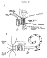
Figure 3 shows two examples of a dual mode hearing device comprising juxtaposed floating mass transducer and electrode(s). In Panel A, the stimulation means of the hearing device are implanted in the middle ear (e.g., the electrode is adjacent to the floating mass transducer housing which is attached to the surface of the round window). In Panel B, the stimulation means of the hearing device are implanted in the inner ear (e.g., the floating mass transducer is connected in series to several electrodes implanted in the cochlea). -
Figure 4 , Panels A, B, and C, show several examples of a hearing device including both two and three stimulation modes (e.g., ultrasonic, mechanical, and electrical). - The present invention relates to implantable medical devices for improving sound perception by individuals with severe to profound hearing loss or tinnitus. In particular, the present invention provides methods and devices for stimulating structures of the ear via multiple signal transducers.
- The present invention provides implantable hearing devices comprising at least two transducers to provide hearing correction across the entire normal audio frequency range for individuals with severe or profound hearing loss or tinnitus. Individuals with residual hearing over one frequency range (e.g., 10-30 dB of useful dynamic range), but no or little hearing over a second frequency range are particularly good candidates for the hearing devices disclosed herein. Additionally, patients who have rejected standard cochlear implants due to medical or performance issues are anticipated to receive benefit from the multi-transducer hearing devices of the present invention.
- According to the invention, a floating mass transducer is used to provide hearing correction in the residual hearing frequency range, and a cochlear implant is used to provide hearing correction in the non-hearing frequency range. As shown in
Figure 1 , Panel A, an individual with residual hearing in the low frequency range receives mechanical stimulation in the low frequency range and electrical stimulation in the high frequency range. Conversely, as shown inFigure 1 , Panel B, an individual with residual hearing in the high frequency range receives mechanical stimulation in the high frequency range and electronic stimulation in the low frequency range. For both patients, some frequencies receive mechanical as well as electronic stimulation. - Mechanical stimulation is provided by the audio and/or ultrasonic floating mass transducer (FMT) component(s) of the hearing device. Briefly, the FMT is a transducer with a mass that vibrates in direct response to an external signal which corresponds to sound waves. The mass is mechanically coupled to a housing which is mountable on a vibratory structure of the ear. Thus, the mechanical vibration of the floating mass is transformed into a vibration of the vibratory structure of the ear (e.g., tympanic membrane, malleus, incus, and stapes, oval window, round window, and cochlea). Each of the vibratory structures of the ear vibrates to some degree when a person with normal hearing hears sound waves. However, hearing loss in a person may be evidenced by one or more vibratory structures vibrating less than normal or not at all. FMTs suitable for use as components of the present invention include but are not limited to those disclosed in
U.S. Patent No. 6,190,305 , hereby incorporated by reference in its entirety. - Electric stimulation is provided by the coclear implant (CI) component of the hearing device. Briefly, the CI delivers electric signals to the cochlea which correspond to ambient sounds. As the cochlea is naturally partitioned into regions responsive to signals in a particular frequency range, an electrode array with a plurality of electrodes is utilized to deliver a cochlea stimulating signal within a preselected frequency range to the appropriate region. The electrical currents and electric fields from each electrode, which may be active simultaneously, stimulate the auditory nerve cells disposed in the modiolus of the cochlea. CIs suitable for use as components of the present invention include but are not limited to those disclosed in
U.S. Patent No. 6,421,569 , incorporated herein. - The partially and totally implantable hearing devices of the present invention take a wide variety of forms. In one example as shown in
Figure 2 Panel A, a floating mass transducer is placed on the ossicular chain and an electrode is placed on the round window. The floating mass transducer imparts vibratory motion to the ear, while the electrode stimulates the cochlea electrically. In another example as shown inFigure 2 Panel B, a floating mass transducer is placed on the ossicular chain and multiple electrodes are placed at different locations around the outside of the cochlea. In a further example as shown inFigure 2 Panel C, a multi-channel electrode is used in combination with a floating mass transducer and either a means for preventing drainage of the cochlear fluid or a means for replacement of the cochlear fluid. Alternatively, both the floating mass transducer and the electrode are placed together on the round window (See, e.g.,Figure 3 Panel A, device comprising a floating mass transducer with an electrode on the surface facing the round window). Suitable configurations for implantation in the inner ear for stimulation of the cochlear fluid comprise either a floating mass transducer connected to an electrode array, or an electrode connected to multiple floating mass transducers (See, e.g.,Figure 3 Panel B). - As shown in
Figure 4 Panel A, some examples of the implantable hearing devices of the present invention provide mechanical stimulation in the form of both an ultrasonic floating mass transducer, and an audio floating mass transducer in addition to electric stimulation. In this way, a single implant provides multiple stimulation modes for patients with especially troublesome hearing loss. -
Figure 3 Panel B andFigure 4 Panel B show inplantable hearing devices according to the present invention. - To facilitate an understanding of the present invention, a number of terms and phrases are defined below:
- As used herein, the term "subject" refers to a human or other animal. It is intended that the term encompass patients, such as hearing impaired patients.
- The terms "hearing impaired subject" and "hearing impaired patient" refer to animals or persons with any degree of loss of hearing that has an impact on the activities of daily living or that requires special assistance or intervention. Subjects with severe (sound detection above 70 dB) to profound (sound detection above 90 dB) hearing loss are preferred candidates for the hearing devices of the present invention. Subjects with severe "tinnitus" or "ringing in the ears" are also expected to receive benefit from the hearing devices disclosed herein.
- As used herein, the terms "external ear canal" and "external auditory meatus" refer to the opening in the skull through which sound reaches the middle ear. The external ear canal extends to the tympanic membrane (or "eardrum"), although the tympanic membrane itself is considered to be part of the middle ear. The external ear canal is lined with skin and due to its resonant characteristics, provides some amplification of sound traveling through the canal. The "outer ear" includes those parts of the ear that are normally visible (e.g., the auricle or pinna, and the surface portions of the external ear canal).
- As used herein, the term "middle ear" refers to the portion of the auditory system that is internal to the tympanic membrane, and including the tympanic membrane, itself. It includes the auditory ossicles (i.e., malleus, incus, and stapes, commonly known as the hammer, anvil, and stirrup) that from a bony chain (e.g., ossicular chain) across the middle ear chamber to conduct and amplify sound waves from the tympanic membrane to the oval window. The ossicles are secured to the walls of the chamber by ligaments. The middle ear is open to the outside environment by means of the eustachian tube.
- As used herein, the term "inner ear" refers to the fluid-filled portion of the ear. Waves relayed by the ossicles to the oval window are created in the fluid, pass through the cochlea, and stimulate the delicate hair-like endings of the receptor cells of the auditory nerve. These receptors generate electrochemical signals which are interpreted by the brain as sound.
- The term "cochlea" refers to the part of the inner ear that is concerned with hearing. The cochlea is a division of the bony labyrinth located anterior to the vestibule, coiled into the form of a snail shell, and consisting of a spiral canal in the petrous part of the temporal bone.
- As used herein, the term "cochlear hair cell" refers to the sound sensing cell of the inner ear, which have modified ciliary structures (e.g., hairs), that enable them to produce an electrical (neural) response to mechanical motion caused by the effect of sound waves on the cochlea. Frequency is detected by the position of the cell in the cochlea and amplitude by the magnitude of the disturbance.
- The term "cochlear fluid" refers to the liquid within the cochlea which transmits vibrations to the hair cells.
- The terms "round window" and "fenestra of the cochlea" refer to an opening in the medial wall of the middle ear leading into the cochlea.
- The term "temporal bone" refers to a large irregular bone situated in the base and side of the skull, consisting of the, squamous, tympanic and petrous. The term "mastoid" refers to the process of the temporal bone behind the ear.
- As used herein, the term "amplifier" refers to a device that produces an electrical output that is a function of the corresponding electrical input parameter, and increases the magnitude of the input by means of energy drawn from an external source (i.e., it introduces gain). "Amplification" refers to the reproduction of an electrical signal by an electronic device, usually at an increased intensity. "Amplification means" refers to the use of an amplifier to amplify a signal. It is intended that the amplification means also includes means to process and/or filter the signal.
- As used herein, the term "receiver" refers to the part of a system that converts transmitted waves into a desired form of output. The range of frequencies over which a receiver operates with a selected performance (i.e., a known level of sensitivity) is the "bandwidth" of the receiver. The "minimal discernible signal" is the smallest value of input power that results in output by the receiver.
- As used herein, the term "transmitter" refers to a device, circuit, or apparatus of a system that is used to transmit an electrical signal to the receiving part of the system. A "transmitter coil" is a device that receives an electrical signal and broadcasts it to a "receiver coil." It is intended that transmitter and receiver coils may be used in conjunction with centering magnets which function to maintain the placement of the coils in a particular position and/or location.
- As used herein, the terms "speaker" and "loudspeaker" refer to electroacoustic devices that convert electrical energy into sound energy. The speaker is the final unit in any sound reproducer or acoustic circuit of any broadcast receiver. It is not intended that the present invention be limited to any particular type of speaker. For example, the term encompasses loudspeakers including but not limited to magnetic, cone, horn, crystal, magnetorestriction, magnetic-armature, electrostatic, and labyrinth speakers. It is also intended that multiple speakers of the same or different configurations will be used in the present invention.
- As used herein, the term "microphone" refers to a device that converts sound energy into electrical energy. It is the converse of the loudspeaker, although in some devices, the speaker-microphone maybe used for both purposes (i.e., a loudspeaker microphone). Various types of microphones are encompassed by this definition, including carbon, capacitor, crystal, moving-coil, and ribbon embodiments. Most microphones operate by converting sound waves into mechanical vibrations that then produce electrical energy. The force exerted by the sound is usually proportional to the sound pressure. In some embodiments, a thin diaphragm is mechanically coupled to a suitable device (e.g., a coil). In alternative embodiments the sound pressure is converted to electrical pressure by direct deformation of suitable magnetorestrictive or piezoelectric crystals (e.g., magnetorestriction and crystal microphones).
- The term "circuit" as used herein, refers to the complete path of an electric current.
- As used herein, the term "transducer" refers to any device that converts a non-electrical parameter (e.g., sound, pressure or light), into electrical signals or vice versa. Microphones are one type of electroacoustic transducer.
- As used herein, the term "resistor" refers to an electronic device that possesses resistance and is selected for this use. It is intended that the term encompass all types of resistors, including but not limited to, fixed-value or adjustable, carbon, wire-wound, and film resistors. The term "resistance" (R; ohm) refers to the tendency of a material to resist the passage of an electric current, and to convert electrical energy into heat energy.
- The term "magnet" refers to a body (e.g., iron, steel or alloy) having the property of attracting iron and producing a magnetic field external to itself, and when freely suspended, of pointing to the poles.
- As used herein, the term "magnetic field" refers to the area surrounding a magnet in which magnetic forces may be detected.
- The term "vibrations" refer to limited reciprocating motions of a particle of an elastic body or medium in alternately opposite directions from its position of equilibrium, when that equilibrium has been disturbed.
- The term "coil" refers to an object made of wire wound in a spiral configuration, used in electronic applications.
- As used herein, the term "electrode" refers to a conductor used to establish electrical contact with a nonmetallic part of a circuit. In preferred embodiments, the term "electrode" refers to a conductor used to impart an electric current into a structure of the ear (e.g., round window, cochlea, etc.). The term "microelectrode array" refers to an ordered set of electrodes with extremely small tips, used to stimulate bioelectric potentials of single cells.
- The term "leads" refers to wires covered with an insulator used for conducting current between device components (e.g., receiver to transducer or receiver to electrode microarray).
- As used herein, the terms "floating mass transducer" and "FMT™" refer to a transducer with a mass that vibrates in direct response to an external signal which corresponds to sound waves. The mass is mechanically coupled to a housing which is mountable on a vibratory structure of the ear. Thus, the mechanical vibration of the floating mass is transformed into a vibration of the vibratory structure allowing the patient to hear. A floating mass transducer can also be utilized as a transducer to transform mechanical vibrations into electrical signals.
- As used herein, the term "soundbridge" refers to medical prostheses that serve to improve the hearing of individuals. Although it is not intended that the present invention be so limited, in particularly preferred embodiments, soundbridges are used to improve the hearing of individuals with sensorineural, conductive (i.e., the ossicular connection is broken, loose, stuck, or missing), or mixed sensorineural and conductive hearing loss. Unlike hearing aids that take a sound and make it louder as it enters the middle ear, in particularly preferred embodiments, soundbridges convert acoustic sound to vibrations inside the middle ear. These vibrations are amplified by device electronics in order to make the vibrations stronger than the patient would normally achieve with sound transmitted through the ear canal and across the eardrum. Since in the most preferred embodiments no portion of the soundbridge is present in the ear canal, problems commonly experienced with hearing aids (e.g., occlusion, discomfort, irritation, soreness, feedback, external ear infections, etc.), are eliminated or reduced.
- In highly preferred embodiments, the soundbridge is divided into two components, with the external portion comprising an audio processor (e.g., comprised of a microphone, battery, and the electronics needed to convert sound to a signal that can be transmitted to the internal portion of the soundbridge) and the internal portion comprising an internal receiving link and a floating mass transducer (FMT™). The audio processor is positioned on the wearer's head with a magnet. A signal from the audio processor is transmitted across the skin to an internal receiver, which then relays the signal via a conductor link to the FMT™. In turn, the FMT™ converts the signal to vibrations that move the bones of the middle ear in a manner similar to the way in which sounds move them. Thus, ambient sounds (e.g., voices, etc.) are picked up by the microphone in the audio processor and converted to an electrical signal within the audio processor. This electrical signal is then transmitted across the skin to the internal receiver which then conveys the signal to the FMT™ via a conducting link, resulting in mechanical vibration of the ossicles, which are then interpreted by the wearer.
- As used herein, the term "battery" refers to a cell that furnishes electric current to the hearing devices of the present invention. In preferred embodiments of the present invention, "rechargeable" batteries are used.
- In other preferred embodiments, the present invention provides a completely implantable system in which the microphone, battery, and electronics are positioned under the patient's skin. In such embodiments, the battery is positioned and designed so as to allow recharging while the battery is implanted (i.e., the battery is recharged while it is in position in situ).
- The term "housing" refers to the structure encasing or enclosing at least one component (e.g., microphone, battery, electronics, transducer, etc.) of the devices of the present invention. In preferred embodiments, the "housing" is produced from a "biocompatible" material. In particularly preferred embodiments, the housing comprises at least one hermetic feedthrough through which leads extend from the component inside the housing to a position outside the housing.
- As used herein, the term "biocompatible" refers to any substance or compound that has minimal (i.e., no significant difference is seen compared to a control) to no irritant or immunological effect on the surrounding tissue. It is also intended that the term be applied in reference to the substances or compounds utilized in order to minimize or to avoid an immunologic reaction to the housing or other aspects of the invention. Particularly preferred biocompatible materials include, but are not limited to titanium, gold, platinum, sapphire, and ceramics.
- As used herein, the term "implantable" refers to any device that may be surgically implanted in a patient. It is intended that the term encompass various types of implants. In preferred embodiments, the device may be implanted under the skin (i.e., subcutaneous), or placed at any other location suited for the use of the device (e.g., within temporal bone, middle ear or inner ear). An implanted device is one that has been implanted within a subject, while a device that is "external" to the subject is not implanted within the subject (i.e., the device is located externally to the subject's skin). Similarly, the term "surgically implanting" refers to the medical procedure whereby the hearing device is placed within a living body.
- As used herein, the term "hermetically sealed" refers to a device or object that is sealed in a manner that liquids or gases located outside the device are prevented from entering the interior of the device, to at least some degree. "Completely hermetically sealed" refers to a device or object that is sealed in a manner such that no detectable liquid or gas located outside the device enters the interior of the device. It is intended that the sealing be accomplished by a variety of means, including but not limited to mechanical, glue or sealants, etc. In particularly preferred embodiments, the hermetically sealed device is made so that it is completely leak-proof (i.e., no liquid or gas is allowed to enter the interior of the device at all).
- As used herein, the term "reproduction of sound" refers to the reproduction of sound information from an audiofrequency source of electrical signals. It is intended that the term encompass complete sound reproduction systems (i.e., comprising the original source of audio information, preamplifier, and control circuits, audiofrequency power amplifier[s] and loudspeaker[s]). It is intended that the term encompass monophonic, as well as stereophonic sound reproduction, including stereophonic broadcast transmission. In some embodiments, a sound reproduction system composed of high-quality components, and which reproduces the original audio information faithfully and with very low noise levels, is referred to as a "high-fidelity" system (hi-fi). As used herein, the term "audio processor" refers to any device or component that processes sound for any purpose.
- As used herein, the term "acoustic wave" and "sound wave" refer to a wave that is transmitted through a solid, liquid, and/or gaseous material as a result of the mechanical vibrations of the particles forming the material. The normal mode of wave propagation is longitudinal (i.e., the direction of motion of the particles is parallel to the direction of wave propagation), the wave therefore consists of compressions and rarefactions of the material. It is intended that the present invention encompass waves with various frequencies, although waves falling within the audible range of the human ear (e.g., approximately 20 Hz to 20 kHz) are particularly preferred. Waves with frequencies greater than approximately 20 kHz are "ultrasonic" waves.
- As used herein, the term "frequency" (v or f) refers to the number of complete cycles of a periodic quantity occurring in a unit of time. The unit of frequency is the "hertz," corresponding to the frequency of a periodic phenomenon that has a period of one second. Table 1 below lists various ranges of frequencies that form part of a larger continuous series of frequencies. Internationally agreed radiofrequency bands are shown in this table. Microwave frequencies ranging from VHF to EHF bands (i.e., 0225 to 100 GHz) are usually subdivided into bands designated by the letters, P, L, S, X, K, Q, V, and W.
TABLE 1 Radiofrequency Bands Frequency Band Wavelength 300 to 30 GHz Extremely High Frequency (EHF) 1 mm to 1 cm 30 to 3 GHz Superhigh Frequency (SHF) 1 cm to 10 cm 3 to 0.3 GHz Ultrahigh Frequency (UHF) 10 cm to 1 m 300 to 30 MHz Very High Frequency (VHF) 1 m to 10 m 30 to 3 MHz High Frequency (HF) 10 m to 100 m 3 to 0.3 MHz Medium Frequency (MF) 100 m to 1000 m 300 to 30 kHz Low Frequency (LF) 1 km to 10 km 30 to 3 kHz Very Low Frequency (VLF) 10 km to 100 km - As used herein, the term "gain," measured in decibels, is used as a measure of the ability of an electronic circuit, device, or apparatus to increase the magnitude of a given electrical input parameter. In a power amplifier, the gain is the ratio of the power output to the power input of the amplifier. "Gain control" (or "volume control") is a circuit or device that varies the amplitude of the output signal from an amplifier.
- As used herein, the term "decibel" (dB) is a dimensionless unit used to express the ratio of two powers, voltages, currents, or sound intensities. It is 10x the common logarithm of the power ratio. If two power values (P1 and P2) differ by n decibels, then n = 10 log10(P2/P1), or P2/P1 = 10 n/10. If P1 and P2 are the input and output powers, respectively, of an electric network, if n is positive (i.e., P2>P1), there is a gain in power. If n is negative (i.e., P1>P2), there is a power loss.
- As used herein, the terms "carrier wave" and "carrier" refer to a wave that is intended to be modulated by a signal that is to be transmitted. The process of modulation produces spectral components termed "sidebands" that fall into frequency bands at either the upper ("upper sideband") or lower ("lower sideband") side of the carrier frequency. A sideband in which some of the spectral components are greatly attenuated is referred to a "vestigial sideband." Generally, these components correspond to the highest frequency in the modulating signals. A single frequency in a sideband is referred to as a "side frequency," while the "baseband" is the frequency band occupied by all of the transmitted modulating signals.
- The term "modulation" is used in general reference, to the alteration or modification of any electronic parameter by another. For example, it encompasses the process by which certain characteristics of one wave (the "carrier wave" or "carrier signal") are modulated or modified in accordance with the characteristic of another wave (the "modulating wave"). The reverse process is "demodulation," in which an output wave is obtained that has the characteristics of the original modulating wave or signal. Characteristics of the carrier that may be modulated include the amplitude, and phase angle. Modulation by an undesirable signal is referred to as "cross modulation," while "multiple modulation" is a succession of processes of modulation in which the whole, or part of the modulated wave from one process becomes the modulating wave for the next.
- As used herein, the term "demodulator" ("detector") refers to a circuit, apparatus, or circuit element that demodulates the received signal (i.e., extracts the signal from a carrier, with minimum distortion). "A modulator" is any device that effects modulation.
- As used herein, the term "dielectric" refers to a solid, liquid, or gaseous material that can sustain an electric field and act as an insulator (i.e., a material that is used to prevent the loss of electric charge or current from a conductor, insulators have a very high resistance to electric current, so that the current flow through the material is usually negligible).
- As used herein, the term "electronic device" refers to a device or object that utilizes the properties of electrons or ions moving in a vacuum, gas, or semiconductor. "Electronic circuitry" refers to the path of electron or ion movement, as well as the direction provided by the device or object to the electrons or ions. A "circuit" or "electronics package" is a combination of a number of electrical devices and conductors that when connected together, form a conducting path to fulfill a desired function, such as amplification, filtering, or oscillation. Any constituent part of the circuit other than the interconnections is referred to as a "circuit element." A circuit may be comprised of discrete components, or it may be an "integrated circuit." A circuit is said to be "closed," when it forms a continuous path for current. It is contemplated that any number of devices be included within an electronics package. It is further intended that various components be included in multiple electronics packages that work cooperatively to amplify sound. In some embodiments, the "vocal electronics" package refers to the entire system used to improve and/or amplify sound production.
- As used herein, the term "electret" refers to a substance that is permanently electrified, and has oppositely charged extremities.
- As used herein, the term "reset" refers to the restoration of an electrical or electronic device or apparatus to its original state following operation of the equipment.
- As used herein, the term "residual charge" refers to the portion of a charge stored in a capacitor that is retained when the capacitor is rapidly discharged, and may be subsequently withdrawn. Although it is not necessary to understand the mechanism to use the present invention, and the present invention present invention is not limited to any particular mechanism of action, it is hypothesized that this results from viscous movement of the dielectric under charge causing some of the charge to penetrate the dielectric and therefore, become relatively remote from the plates; only the charge near the plates is removed by rapid discharge.
- As used herein, the term "current" refers to the rate of flow of electricity. The current is usually expressed in amperes; the symbol used is "I."
- As used herein, the term "residual current" refers to a current that flows for a short time in the external circuit of an active electronic device after the power supply to the device has been turned off. The residual current results from the finite velocity of the charge carriers passing through the device. The term "active" is used in reference to any device, component or circuit that introduces gain or has a directional function. An "active current," "active component," energy component," "power component" or "in-phase component of the current" refers to the component that is in phase with the voltage, alternative current, and voltage being regarded as vector quantities. The term "passive" refers to any device, component or circuit that does not introduce gain, or does not have a directional function. It is intended that the term encompass pure resistance, capacitance, inductance, or a combination of these.
- As used herein, the terms "power source" and "power supply" refer to any source of electrical power in a form that is suitable for operating electronic circuits. Alternating current power may be derived either directly or by means of a suitable transformer. "Alternating current" refers to an electric current whose direction in the circuit is periodically reversed with a frequency f, that is independent of the circuit constants. Direct current power may be supplied from various sources, including, but not limited to batteries, suitable rectifier/filter circuits, or from a converter. "Direct current" refers to an unidirectional current of substantially constant value. The term also encompasses embodiments that include a "bus" to supply power to several circuits or to several different points in one circuit. A "power pack" is used in reference to a device that converts power from an alternating current or direct current supply, into a form that is suitable for operating electronic device(s).
- The term "piezoelectric effect" refers to the property of certain crystalline or ceramic materials to emit electricity when deformed and to deform when an electric current is passed across them, a mechanism of interconverting electrical and acoustic energy; an ultrasound transducer sends and receives acoustic energy using this effect.
- The term "cochlear implant" refers to an electronic device implanted under the skin with electrodes in the middle ear on the promontory or cochlear window or in the inner ear in the cochlea to create sound sensation in total sensory deafness. A microphone behind the ear feeds sound waves into a microprocessor carried on the body, which analyzes the data and sends information back to a radio transmitter that triggers the electrodes in the middle or inner ear to produce the appropriate electrical pulses. This does not enable the patient actually to hear, but rather to distinguish different sounds according to the neural sensation they produce.
- As used herein, the term "electronics" refers to a conductor used to make electrical contact with some part of a circuit.
- The term "ominidirectional microphone" as used herein refers to a microphone that picks up sound at essentially equal levels in all directions. The coverage pattern is essentially 360-degrees with essentially no angle of rejection. In contrast, the term "bidirectional microphone" refers to a microphone that picks up sound essentially equally from two directions. This type of microphone picks up sound from two directions and largely rejects sound from the sides.
- As used herein, the term "channel" refers to a circuit or signal path within a piece of equipment. For example, in a mixer it refers to an input channel (all of the controls and circuitry that affects a single microphone or line-level device), or an output channel (all of the controls and circuitry that affects a single output).
- The term "resonant frequency" as used herein refers to the frequency at which a piezoelectric ceramic will vibrate most efficiently (will produce the highest output with the least amount of voltage applied). The term "resonance" refers to a natural periodicity, or the reinforcement associated with this periodicity.
- As used herein the term "block" refers to a number or quantity of related components dealt with as a single unit.
- The term "signal" refers to an electrical current present on a wire or in a circuit that represents a soundwave.
- All publications and patents mentioned in the above specification are herein incorporated by reference. Various modifications and variations of the described method and system of the invention will be apparent to those skilled in the art without departing from the scope and spirit of the invention. Although the invention has been described in connection with specific preferred embodiments, it should be understood that the invention as claimed should not be unduly limited to such specific embodiments. Indeed, various modifications of the described modes for carrying out the invention which are obvious to those skilled in the relevant fields are intended to be within the scope of the following claims.
Claims (3)
- A device for improving hearing in a subject, comprising:a) a receiver;b) a microphone operably linked to said receiver;c) an array of electrical transducers;d) a mechanical transducer, wherein said mechanical transducer is a floating mass transducer; ande) output channel leads with a proximal end operably connected to said receiver, wherein said array of electrical transducers and said floating mass transducer are connected in series along said output channel leads, wherein said output channel leads are connected to only one mechanical transducer, that being said floating mass transducer, and wherein all of the electrical transducers in said array of electrical transducers that are connected to said output channel leads are distal to said floating mass transducer and are configured for implanting in a subject's cochlea.
- The device of Claim 1, wherein said receiver is configured for implantation within said subject's mastoid bone.
- The device of Claim 1 or 2 wherein said mechanical transducer has a resonant frequency between 250 and 10,000 hertz.
Applications Claiming Priority (5)
| Application Number | Priority Date | Filing Date | Title |
|---|---|---|---|
| US40939402P | 2002-09-10 | 2002-09-10 | |
| US409394P | 2002-09-10 | ||
| US10/660,283 US20040133250A1 (en) | 2002-09-10 | 2003-09-10 | Implantable medical devices with multiple transducers |
| US660283 | 2003-09-10 | ||
| PCT/US2003/028672 WO2004024212A2 (en) | 2002-09-10 | 2003-09-10 | Implantable medical devices with multiple transducers |
Publications (3)
| Publication Number | Publication Date |
|---|---|
| EP1536852A2 EP1536852A2 (en) | 2005-06-08 |
| EP1536852A4 EP1536852A4 (en) | 2007-07-25 |
| EP1536852B1 true EP1536852B1 (en) | 2016-11-16 |
Family
ID=31997817
Family Applications (1)
| Application Number | Title | Priority Date | Filing Date |
|---|---|---|---|
| EP03752302.4A Expired - Lifetime EP1536852B1 (en) | 2002-09-10 | 2003-09-10 | Implantable medical device with multiple transducers |
Country Status (4)
| Country | Link |
|---|---|
| US (2) | US20040133250A1 (en) |
| EP (1) | EP1536852B1 (en) |
| AU (1) | AU2003270597A1 (en) |
| WO (1) | WO2004024212A2 (en) |
Families Citing this family (45)
| Publication number | Priority date | Publication date | Assignee | Title |
|---|---|---|---|---|
| US7044942B2 (en) | 2001-10-24 | 2006-05-16 | Med-El Elektromedizinische Geraete Gmbh | Implantable fluid delivery apparatuses and implantable electrode |
| US20070088335A1 (en) * | 2001-10-24 | 2007-04-19 | Med-El Elektromedizinische Geraete Gmbh | Implantable neuro-stimulation electrode with fluid reservoir |
| AUPS322702A0 (en) * | 2002-06-28 | 2002-07-18 | Cochlear Limited | Cochlear implant electrode array |
| EP1572287B1 (en) * | 2002-12-02 | 2011-02-23 | Med-El Elektromedizinische Geräte GmbH | Fluid switch controlled trans-cutaneously via a magnetic force |
| WO2005097255A1 (en) * | 2004-04-02 | 2005-10-20 | Advanced Bionics Corporation | Electric and acoustic stimulation fitting systems and methods |
| US8244365B2 (en) * | 2004-05-10 | 2012-08-14 | Cochlear Limited | Simultaneous delivery of electrical and acoustical stimulation in a hearing prosthesis |
| US8086319B2 (en) * | 2004-05-10 | 2011-12-27 | Cochlear Limited | Cochlear implant fitting |
| US8265765B2 (en) | 2005-12-08 | 2012-09-11 | Cochlear Limited | Multimodal auditory fitting |
| US20070203536A1 (en) * | 2006-02-07 | 2007-08-30 | Ingeborg Hochmair | Tinnitus Suppressing Cochlear Implant |
| US7720542B2 (en) | 2006-07-17 | 2010-05-18 | Med-El Elektromedizinische Geraete Gmbh | Remote sensing and actuation of fluid in cranial implants |
| RU2465876C2 (en) * | 2006-07-17 | 2012-11-10 | Мед-Эль Электромедицинише Герэте Гмбх | System of connection with internal ear |
| AR062036A1 (en) * | 2006-07-24 | 2008-08-10 | Med El Elektromed Geraete Gmbh | MOBILE COIL ACTUATOR FOR MIDDLE EAR IMPLANTS |
| WO2008058232A2 (en) * | 2006-11-08 | 2008-05-15 | Massachusetts Eye & Ear Infirmary | Spatially-focused actuation in a neural prosthesis |
| AU2007337981A1 (en) * | 2006-12-26 | 2008-07-03 | 3Win N.V. | Device and method for improving hearing |
| US9402990B2 (en) * | 2007-03-20 | 2016-08-02 | Cochlear Limited | Securing an implanted medical device in a patient |
| CN101868983A (en) | 2007-11-22 | 2010-10-20 | 索内提克有限公司 | Method and system for providing a hearing aid |
| WO2009111334A2 (en) * | 2008-02-29 | 2009-09-11 | Otologics, Llc | Improved bi-modal cochlea stimulation |
| US8401213B2 (en) | 2008-03-31 | 2013-03-19 | Cochlear Limited | Snap-lock coupling system for a prosthetic device |
| US20090287277A1 (en) * | 2008-05-19 | 2009-11-19 | Otologics, Llc | Implantable neurostimulation electrode interface |
| US20100069997A1 (en) * | 2008-09-16 | 2010-03-18 | Otologics, Llc | Neurostimulation apparatus |
| AU2009305745B9 (en) * | 2008-10-15 | 2013-07-18 | Med-El Elektromedizinische Geraete Gmbh | Inner ear drug delivery device and method |
| CN102271754B (en) | 2008-11-10 | 2014-07-16 | Med-El电气医疗器械有限公司 | Hydrogel-filled drug delivery reservoirs |
| WO2010068984A1 (en) * | 2008-12-16 | 2010-06-24 | Cochlear Limited | Implantable microphone |
| US9044588B2 (en) * | 2009-04-16 | 2015-06-02 | Cochlear Limited | Reference electrode apparatus and method for neurostimulation implants |
| US8771166B2 (en) | 2009-05-29 | 2014-07-08 | Cochlear Limited | Implantable auditory stimulation system and method with offset implanted microphones |
| US9056204B2 (en) | 2010-10-29 | 2015-06-16 | Cochlear Limited | Universal implant |
| US20120136197A1 (en) * | 2010-11-30 | 2012-05-31 | Van Gerwen Peter B J | Hearing prosthesis having a flexible elongate energy transfer mechanism |
| US11083391B2 (en) | 2011-06-10 | 2021-08-10 | Cochlear Limited | Electrode impedance spectroscopy |
| EP2602001A1 (en) * | 2011-12-08 | 2013-06-12 | BIOTRONIK SE & Co. KG | Medical implant and medical arrangement |
| US9462365B1 (en) | 2012-03-14 | 2016-10-04 | Google Inc. | Structure and manufacture of bone-conduction transducer |
| US8926523B2 (en) | 2012-04-27 | 2015-01-06 | Medtronic, Inc. | Method and apparatus for cardiac function monitoring |
| WO2014011588A1 (en) * | 2012-07-13 | 2014-01-16 | Med-El Elektromedizinische Geraete Gmbh | Implantable fluid delivery system with floating mass transducer driven pump |
| WO2016048936A1 (en) * | 2014-09-23 | 2016-03-31 | Med-El Elektromedizinische Geraete Gmbh | Hybrid electro-mechanical hearing prosthesis system |
| US10341789B2 (en) | 2014-10-20 | 2019-07-02 | Cochlear Limited | Implantable auditory prosthesis with floating mass transducer |
| DE102015101482B3 (en) * | 2015-02-02 | 2016-05-19 | Fraunhofer-Gesellschaft zur Förderung der angewandten Forschung e.V. | Electroacoustic implant |
| US10321247B2 (en) | 2015-11-27 | 2019-06-11 | Cochlear Limited | External component with inductance and mechanical vibratory functionality |
| US10560791B2 (en) | 2016-01-29 | 2020-02-11 | Cochlear Limited | Hybrid electrically- and mechanically-stimulating cochlear implant |
| US11071869B2 (en) | 2016-02-24 | 2021-07-27 | Cochlear Limited | Implantable device having removable portion |
| WO2017213978A1 (en) | 2016-06-06 | 2017-12-14 | Mayo Foundation For Medical Education And Research | Devices and methods for treating tinnitus using electrical stimulation |
| EP3490670A4 (en) * | 2016-07-29 | 2020-03-04 | Helium 3 Resources Pty Ltd | A hearing loss alleviating device and method of use of same |
| CN108245314A (en) * | 2016-12-28 | 2018-07-06 | 中国科学院深圳先进技术研究院 | For carrying out the generating means for the ultrasonic wave that the sense of hearing resumes treatment |
| CN110430848B (en) * | 2017-02-27 | 2021-08-24 | Med-El电气医疗器械有限公司 | Middle ear implant coupler for mechanical cochlear stimulation through round window |
| TW201838602A (en) * | 2017-04-21 | 2018-11-01 | 國立交通大學 | A cochlear implant device and method thereof |
| DE102018220731B3 (en) * | 2018-11-30 | 2020-06-04 | Med-El Elektromedizinische Geräte GmbH | Electroacoustic transducer for implantation in an ear, method for producing such an and cochlear implant system |
| DE102020126712B4 (en) | 2020-10-12 | 2022-06-15 | Audisense Gmbh | Hearing prosthesis with a large number of ultrasonic elements arranged in a row |
Family Cites Families (20)
| Publication number | Priority date | Publication date | Assignee | Title |
|---|---|---|---|---|
| US4419995A (en) * | 1981-09-18 | 1983-12-13 | Hochmair Ingeborg | Single channel auditory stimulation system |
| US4532930A (en) * | 1983-04-11 | 1985-08-06 | Commonwealth Of Australia, Dept. Of Science & Technology | Cochlear implant system for an auditory prosthesis |
| US5176620A (en) * | 1990-10-17 | 1993-01-05 | Samuel Gilman | Hearing aid having a liquid transmission means communicative with the cochlea and method of use thereof |
| US5554096A (en) * | 1993-07-01 | 1996-09-10 | Symphonix | Implantable electromagnetic hearing transducer |
| US5897486A (en) * | 1993-07-01 | 1999-04-27 | Symphonix Devices, Inc. | Dual coil floating mass transducers |
| US6161046A (en) * | 1996-04-09 | 2000-12-12 | Maniglia; Anthony J. | Totally implantable cochlear implant for improvement of partial and total sensorineural hearing loss |
| US6231604B1 (en) * | 1998-02-26 | 2001-05-15 | Med-El Elektromedizinische Gerate Ges.M.B.H | Apparatus and method for combined acoustic mechanical and electrical auditory stimulation |
| US6074422A (en) * | 1998-04-22 | 2000-06-13 | Epic Biosonics Inc. | Inner ear implant device |
| DE19915846C1 (en) * | 1999-04-08 | 2000-08-31 | Implex Hear Tech Ag | Partially implantable system for rehabilitating hearing trouble includes a cordless telemetry device to transfer data between an implantable part, an external unit and an energy supply. |
| US6259951B1 (en) * | 1999-05-14 | 2001-07-10 | Advanced Bionics Corporation | Implantable cochlear stimulator system incorporating combination electrode/transducer |
| WO2000069512A1 (en) * | 1999-05-14 | 2000-11-23 | Advanced Bionics Corporation | Hybrid implantable cochlear stimulator hearing aid system |
| EP1189560B1 (en) | 1999-05-21 | 2006-03-15 | Cochlear Limited | A cochlear implant electrode array |
| DE10015421C2 (en) * | 2000-03-28 | 2002-07-04 | Implex Ag Hearing Technology I | Partially or fully implantable hearing system |
| DE10018360C2 (en) * | 2000-04-13 | 2002-10-10 | Cochlear Ltd | At least partially implantable system for the rehabilitation of a hearing impairment |
| DE10018334C1 (en) * | 2000-04-13 | 2002-02-28 | Implex Hear Tech Ag | At least partially implantable system for the rehabilitation of a hearing impairment |
| DE10018361C2 (en) * | 2000-04-13 | 2002-10-10 | Cochlear Ltd | At least partially implantable cochlear implant system for the rehabilitation of a hearing disorder |
| US6611718B2 (en) * | 2000-06-19 | 2003-08-26 | Yitzhak Zilberman | Hybrid middle ear/cochlea implant system |
| DE10039401C2 (en) * | 2000-08-11 | 2002-06-13 | Implex Ag Hearing Technology I | At least partially implantable hearing system |
| DE10046938A1 (en) * | 2000-09-21 | 2002-04-25 | Implex Ag Hearing Technology I | At least partially implantable hearing system with direct mechanical stimulation of a lymphatic space in the inner ear |
| US6620094B2 (en) * | 2001-11-21 | 2003-09-16 | Otologics, Llc | Method and apparatus for audio input to implantable hearing aids |
-
2003
- 2003-09-10 AU AU2003270597A patent/AU2003270597A1/en not_active Abandoned
- 2003-09-10 US US10/660,283 patent/US20040133250A1/en not_active Abandoned
- 2003-09-10 WO PCT/US2003/028672 patent/WO2004024212A2/en not_active Application Discontinuation
- 2003-09-10 EP EP03752302.4A patent/EP1536852B1/en not_active Expired - Lifetime
-
2007
- 2007-01-17 US US11/654,917 patent/US8285384B2/en active Active
Non-Patent Citations (1)
| Title |
|---|
| None * |
Also Published As
| Publication number | Publication date |
|---|---|
| EP1536852A2 (en) | 2005-06-08 |
| US20040133250A1 (en) | 2004-07-08 |
| US20070282397A1 (en) | 2007-12-06 |
| WO2004024212A3 (en) | 2004-06-03 |
| EP1536852A4 (en) | 2007-07-25 |
| AU2003270597A8 (en) | 2004-04-30 |
| WO2004024212A2 (en) | 2004-03-25 |
| AU2003270597A1 (en) | 2004-04-30 |
| US8285384B2 (en) | 2012-10-09 |
Similar Documents
| Publication | Publication Date | Title |
|---|---|---|
| EP1536852B1 (en) | Implantable medical device with multiple transducers | |
| US7747026B2 (en) | Soundbridge test system | |
| US8246532B2 (en) | Bone conductive devices for improving hearing | |
| US5879283A (en) | Implantable hearing system having multiple transducers | |
| US6010532A (en) | Dual path implantable hearing assistance device | |
| US5999856A (en) | Implantable hearing assistance system with calibration and auditory response testing | |
| US5997466A (en) | Implantable hearing system having multiple transducers | |
| US8641596B2 (en) | Wireless communication in a multimodal auditory prosthesis | |
| US20080255406A1 (en) | Implantable Auditory Stimulation Systems Having a Transducer and a Transduction Medium | |
| WO2009124008A1 (en) | Bone conduction device for a single sided deaf recipient | |
| WO2004105431A2 (en) | Hearing aid | |
| EP1251810B1 (en) | Method for testing middle ear implants |
Legal Events
| Date | Code | Title | Description |
|---|---|---|---|
| PUAI | Public reference made under article 153(3) epc to a published international application that has entered the european phase |
Free format text: ORIGINAL CODE: 0009012 |
|
| 17P | Request for examination filed |
Effective date: 20050310 |
|
| AK | Designated contracting states |
Kind code of ref document: A2 Designated state(s): AT BE BG CH CY CZ DE DK EE ES FI FR GB GR HU IE IT LI LU MC NL PT RO SE SI SK TR |
|
| AX | Request for extension of the european patent |
Extension state: AL LT LV MK |
|
| A4 | Supplementary search report drawn up and despatched |
Effective date: 20070608 |
|
| RIC1 | Information provided on ipc code assigned before grant |
Ipc: A61N 1/05 20060101ALI20070601BHEP Ipc: A61N 1/36 20060101AFI20070601BHEP Ipc: H04R 25/00 20060101ALI20070601BHEP |
|
| DA4 | Supplementary search report drawn up and despatched (deleted) | ||
| RA4 | Supplementary search report drawn up and despatched (corrected) |
Effective date: 20070716 |
|
| 17Q | First examination report despatched |
Effective date: 20071019 |
|
| RAP1 | Party data changed (applicant data changed or rights of an application transferred) |
Owner name: MED-EL ELEKTROMEDIZINISCHE GERAETE GMBH |
|
| GRAP | Despatch of communication of intention to grant a patent |
Free format text: ORIGINAL CODE: EPIDOSNIGR1 |
|
| GRAS | Grant fee paid |
Free format text: ORIGINAL CODE: EPIDOSNIGR3 |
|
| INTG | Intention to grant announced |
Effective date: 20160819 |
|
| RIN1 | Information on inventor provided before grant (corrected) |
Inventor name: BALL, GEOFFREY, R. Inventor name: SCHMIDT, MARCUS |
|
| GRAA | (expected) grant |
Free format text: ORIGINAL CODE: 0009210 |
|
| AK | Designated contracting states |
Kind code of ref document: B1 Designated state(s): AT BE BG CH CY CZ DE DK EE ES FI FR GB GR HU IE IT LI LU MC NL PT RO SE SI SK TR |
|
| AX | Request for extension of the european patent |
Extension state: AL LT LV MK |
|
| REG | Reference to a national code |
Ref country code: GB Ref legal event code: FG4D |
|
| REG | Reference to a national code |
Ref country code: CH Ref legal event code: EP |
|
| REG | Reference to a national code |
Ref country code: IE Ref legal event code: FG4D |
|
| REG | Reference to a national code |
Ref country code: AT Ref legal event code: REF Ref document number: 845347 Country of ref document: AT Kind code of ref document: T Effective date: 20161215 |
|
| REG | Reference to a national code |
Ref country code: DE Ref legal event code: R096 Ref document number: 60349616 Country of ref document: DE |
|
| REG | Reference to a national code |
Ref country code: NL Ref legal event code: MP Effective date: 20161116 |
|
| REG | Reference to a national code |
Ref country code: LT Ref legal event code: MG9D |
|
| REG | Reference to a national code |
Ref country code: AT Ref legal event code: MK05 Ref document number: 845347 Country of ref document: AT Kind code of ref document: T Effective date: 20161116 |
|
| PG25 | Lapsed in a contracting state [announced via postgrant information from national office to epo] |
Ref country code: SE Free format text: LAPSE BECAUSE OF FAILURE TO SUBMIT A TRANSLATION OF THE DESCRIPTION OR TO PAY THE FEE WITHIN THE PRESCRIBED TIME-LIMIT Effective date: 20161116 Ref country code: NL Free format text: LAPSE BECAUSE OF FAILURE TO SUBMIT A TRANSLATION OF THE DESCRIPTION OR TO PAY THE FEE WITHIN THE PRESCRIBED TIME-LIMIT Effective date: 20161116 Ref country code: GR Free format text: LAPSE BECAUSE OF FAILURE TO SUBMIT A TRANSLATION OF THE DESCRIPTION OR TO PAY THE FEE WITHIN THE PRESCRIBED TIME-LIMIT Effective date: 20170217 |
|
| PG25 | Lapsed in a contracting state [announced via postgrant information from national office to epo] |
Ref country code: PT Free format text: LAPSE BECAUSE OF FAILURE TO SUBMIT A TRANSLATION OF THE DESCRIPTION OR TO PAY THE FEE WITHIN THE PRESCRIBED TIME-LIMIT Effective date: 20170316 Ref country code: AT Free format text: LAPSE BECAUSE OF FAILURE TO SUBMIT A TRANSLATION OF THE DESCRIPTION OR TO PAY THE FEE WITHIN THE PRESCRIBED TIME-LIMIT Effective date: 20161116 Ref country code: ES Free format text: LAPSE BECAUSE OF FAILURE TO SUBMIT A TRANSLATION OF THE DESCRIPTION OR TO PAY THE FEE WITHIN THE PRESCRIBED TIME-LIMIT Effective date: 20161116 Ref country code: FI Free format text: LAPSE BECAUSE OF FAILURE TO SUBMIT A TRANSLATION OF THE DESCRIPTION OR TO PAY THE FEE WITHIN THE PRESCRIBED TIME-LIMIT Effective date: 20161116 |
|
| PG25 | Lapsed in a contracting state [announced via postgrant information from national office to epo] |
Ref country code: RO Free format text: LAPSE BECAUSE OF FAILURE TO SUBMIT A TRANSLATION OF THE DESCRIPTION OR TO PAY THE FEE WITHIN THE PRESCRIBED TIME-LIMIT Effective date: 20161116 Ref country code: EE Free format text: LAPSE BECAUSE OF FAILURE TO SUBMIT A TRANSLATION OF THE DESCRIPTION OR TO PAY THE FEE WITHIN THE PRESCRIBED TIME-LIMIT Effective date: 20161116 Ref country code: SK Free format text: LAPSE BECAUSE OF FAILURE TO SUBMIT A TRANSLATION OF THE DESCRIPTION OR TO PAY THE FEE WITHIN THE PRESCRIBED TIME-LIMIT Effective date: 20161116 Ref country code: DK Free format text: LAPSE BECAUSE OF FAILURE TO SUBMIT A TRANSLATION OF THE DESCRIPTION OR TO PAY THE FEE WITHIN THE PRESCRIBED TIME-LIMIT Effective date: 20161116 Ref country code: CZ Free format text: LAPSE BECAUSE OF FAILURE TO SUBMIT A TRANSLATION OF THE DESCRIPTION OR TO PAY THE FEE WITHIN THE PRESCRIBED TIME-LIMIT Effective date: 20161116 |
|
| REG | Reference to a national code |
Ref country code: DE Ref legal event code: R097 Ref document number: 60349616 Country of ref document: DE |
|
| PG25 | Lapsed in a contracting state [announced via postgrant information from national office to epo] |
Ref country code: BE Free format text: LAPSE BECAUSE OF FAILURE TO SUBMIT A TRANSLATION OF THE DESCRIPTION OR TO PAY THE FEE WITHIN THE PRESCRIBED TIME-LIMIT Effective date: 20161116 Ref country code: BG Free format text: LAPSE BECAUSE OF FAILURE TO SUBMIT A TRANSLATION OF THE DESCRIPTION OR TO PAY THE FEE WITHIN THE PRESCRIBED TIME-LIMIT Effective date: 20170216 Ref country code: IT Free format text: LAPSE BECAUSE OF FAILURE TO SUBMIT A TRANSLATION OF THE DESCRIPTION OR TO PAY THE FEE WITHIN THE PRESCRIBED TIME-LIMIT Effective date: 20161116 |
|
| PLBE | No opposition filed within time limit |
Free format text: ORIGINAL CODE: 0009261 |
|
| STAA | Information on the status of an ep patent application or granted ep patent |
Free format text: STATUS: NO OPPOSITION FILED WITHIN TIME LIMIT |
|
| REG | Reference to a national code |
Ref country code: FR Ref legal event code: PLFP Year of fee payment: 15 |
|
| 26N | No opposition filed |
Effective date: 20170817 |
|
| PG25 | Lapsed in a contracting state [announced via postgrant information from national office to epo] |
Ref country code: SI Free format text: LAPSE BECAUSE OF FAILURE TO SUBMIT A TRANSLATION OF THE DESCRIPTION OR TO PAY THE FEE WITHIN THE PRESCRIBED TIME-LIMIT Effective date: 20161116 |
|
| REG | Reference to a national code |
Ref country code: CH Ref legal event code: PL |
|
| GBPC | Gb: european patent ceased through non-payment of renewal fee |
Effective date: 20170910 |
|
| PG25 | Lapsed in a contracting state [announced via postgrant information from national office to epo] |
Ref country code: MC Free format text: LAPSE BECAUSE OF FAILURE TO SUBMIT A TRANSLATION OF THE DESCRIPTION OR TO PAY THE FEE WITHIN THE PRESCRIBED TIME-LIMIT Effective date: 20161116 |
|
| REG | Reference to a national code |
Ref country code: IE Ref legal event code: MM4A |
|
| PG25 | Lapsed in a contracting state [announced via postgrant information from national office to epo] |
Ref country code: LU Free format text: LAPSE BECAUSE OF NON-PAYMENT OF DUE FEES Effective date: 20170910 |
|
| PG25 | Lapsed in a contracting state [announced via postgrant information from national office to epo] |
Ref country code: LI Free format text: LAPSE BECAUSE OF NON-PAYMENT OF DUE FEES Effective date: 20170930 Ref country code: IE Free format text: LAPSE BECAUSE OF NON-PAYMENT OF DUE FEES Effective date: 20170910 Ref country code: CH Free format text: LAPSE BECAUSE OF NON-PAYMENT OF DUE FEES Effective date: 20170930 Ref country code: GB Free format text: LAPSE BECAUSE OF NON-PAYMENT OF DUE FEES Effective date: 20170910 |
|
| REG | Reference to a national code |
Ref country code: FR Ref legal event code: PLFP Year of fee payment: 16 |
|
| PG25 | Lapsed in a contracting state [announced via postgrant information from national office to epo] |
Ref country code: HU Free format text: LAPSE BECAUSE OF FAILURE TO SUBMIT A TRANSLATION OF THE DESCRIPTION OR TO PAY THE FEE WITHIN THE PRESCRIBED TIME-LIMIT; INVALID AB INITIO Effective date: 20030910 |
|
| PG25 | Lapsed in a contracting state [announced via postgrant information from national office to epo] |
Ref country code: CY Free format text: LAPSE BECAUSE OF NON-PAYMENT OF DUE FEES Effective date: 20161116 |
|
| PG25 | Lapsed in a contracting state [announced via postgrant information from national office to epo] |
Ref country code: TR Free format text: LAPSE BECAUSE OF FAILURE TO SUBMIT A TRANSLATION OF THE DESCRIPTION OR TO PAY THE FEE WITHIN THE PRESCRIBED TIME-LIMIT Effective date: 20161116 |
|
| PGFP | Annual fee paid to national office [announced via postgrant information from national office to epo] |
Ref country code: DE Payment date: 20220927 Year of fee payment: 20 |
|
| PGFP | Annual fee paid to national office [announced via postgrant information from national office to epo] |
Ref country code: FR Payment date: 20220926 Year of fee payment: 20 |
|
| REG | Reference to a national code |
Ref country code: DE Ref legal event code: R071 Ref document number: 60349616 Country of ref document: DE |