EP1537837A2 - Stent delivery system - Google Patents
Stent delivery system Download PDFInfo
- Publication number
- EP1537837A2 EP1537837A2 EP05004256A EP05004256A EP1537837A2 EP 1537837 A2 EP1537837 A2 EP 1537837A2 EP 05004256 A EP05004256 A EP 05004256A EP 05004256 A EP05004256 A EP 05004256A EP 1537837 A2 EP1537837 A2 EP 1537837A2
- Authority
- EP
- European Patent Office
- Prior art keywords
- stent
- securement
- sheath
- catheter
- distal end
- Prior art date
- Legal status (The legal status is an assumption and is not a legal conclusion. Google has not performed a legal analysis and makes no representation as to the accuracy of the status listed.)
- Withdrawn
Links
Images


Classifications
-
- A—HUMAN NECESSITIES
- A61—MEDICAL OR VETERINARY SCIENCE; HYGIENE
- A61F—FILTERS IMPLANTABLE INTO BLOOD VESSELS; PROSTHESES; DEVICES PROVIDING PATENCY TO, OR PREVENTING COLLAPSING OF, TUBULAR STRUCTURES OF THE BODY, e.g. STENTS; ORTHOPAEDIC, NURSING OR CONTRACEPTIVE DEVICES; FOMENTATION; TREATMENT OR PROTECTION OF EYES OR EARS; BANDAGES, DRESSINGS OR ABSORBENT PADS; FIRST-AID KITS
- A61F2/00—Filters implantable into blood vessels; Prostheses, i.e. artificial substitutes or replacements for parts of the body; Appliances for connecting them with the body; Devices providing patency to, or preventing collapsing of, tubular structures of the body, e.g. stents
- A61F2/95—Instruments specially adapted for placement or removal of stents or stent-grafts
- A61F2/958—Inflatable balloons for placing stents or stent-grafts
- A61F2002/9583—Means for holding the stent on the balloon, e.g. using protrusions, adhesives or an outer sleeve
-
- A—HUMAN NECESSITIES
- A61—MEDICAL OR VETERINARY SCIENCE; HYGIENE
- A61F—FILTERS IMPLANTABLE INTO BLOOD VESSELS; PROSTHESES; DEVICES PROVIDING PATENCY TO, OR PREVENTING COLLAPSING OF, TUBULAR STRUCTURES OF THE BODY, e.g. STENTS; ORTHOPAEDIC, NURSING OR CONTRACEPTIVE DEVICES; FOMENTATION; TREATMENT OR PROTECTION OF EYES OR EARS; BANDAGES, DRESSINGS OR ABSORBENT PADS; FIRST-AID KITS
- A61F2/00—Filters implantable into blood vessels; Prostheses, i.e. artificial substitutes or replacements for parts of the body; Appliances for connecting them with the body; Devices providing patency to, or preventing collapsing of, tubular structures of the body, e.g. stents
- A61F2/95—Instruments specially adapted for placement or removal of stents or stent-grafts
- A61F2/962—Instruments specially adapted for placement or removal of stents or stent-grafts having an outer sleeve
- A61F2/966—Instruments specially adapted for placement or removal of stents or stent-grafts having an outer sleeve with relative longitudinal movement between outer sleeve and prosthesis, e.g. using a push rod
- A61F2002/9665—Instruments specially adapted for placement or removal of stents or stent-grafts having an outer sleeve with relative longitudinal movement between outer sleeve and prosthesis, e.g. using a push rod with additional retaining means
-
- A—HUMAN NECESSITIES
- A61—MEDICAL OR VETERINARY SCIENCE; HYGIENE
- A61F—FILTERS IMPLANTABLE INTO BLOOD VESSELS; PROSTHESES; DEVICES PROVIDING PATENCY TO, OR PREVENTING COLLAPSING OF, TUBULAR STRUCTURES OF THE BODY, e.g. STENTS; ORTHOPAEDIC, NURSING OR CONTRACEPTIVE DEVICES; FOMENTATION; TREATMENT OR PROTECTION OF EYES OR EARS; BANDAGES, DRESSINGS OR ABSORBENT PADS; FIRST-AID KITS
- A61F2250/00—Special features of prostheses classified in groups A61F2/00 - A61F2/26 or A61F2/82 or A61F9/00 or A61F11/00 or subgroups thereof
- A61F2250/0014—Special features of prostheses classified in groups A61F2/00 - A61F2/26 or A61F2/82 or A61F9/00 or A61F11/00 or subgroups thereof having different values of a given property or geometrical feature, e.g. mechanical property or material property, at different locations within the same prosthesis
- A61F2250/0029—Special features of prostheses classified in groups A61F2/00 - A61F2/26 or A61F2/82 or A61F9/00 or A61F11/00 or subgroups thereof having different values of a given property or geometrical feature, e.g. mechanical property or material property, at different locations within the same prosthesis differing in bending or flexure capacity
Definitions
- This invention relates to an assembly and method for delivering and deploying an expandable stent, particularly within a lumen of a body vessel. More specifically, this invention relates an assembly and method for delivering and deploying a balloon expandable stent, and most notably to stent securement devices positioned over the balloon and stent.
- a stent is a general cylindrical prosthesis introduced via a 'catheter into a lumen of a body vessel, the stent being in a configuration having a generally reduced diameter and then being expanded to the diameter of the vessel. In its expanded configuration, the stent supports and reinforces the vessel walls while maintaining the vessel in an open, unobstructed condition.
- Both self-expanding and inflation (as by a balloon) expandable stents are well-known and widely available.
- Self expanding stents must be maintained under positive external pressure in order to maintain their reduced diameter configuration during delivery of the stent to its deployment site.
- Inflation expandable stents also known as balloon expandable stents
- the present invention is particularly concerned with stent securement in the delivery and deployment of inflation expandable stents.
- angioplasty procedure there may be restenosis of the artery, which either necessitates another angioplasty procedure, a surgical bypass procedure, or some method of repairing or strengthening the area.
- a physician may implant an intravascular prosthesis for maintaining vascular patency, i.e. a stent, inside the artery at the lesion.
- the stent is expanded to a larger diameter following placement in the vasculature, often by a balloon portion of the catheter.
- Stents delivered to a restricted coronary artery, expanded to a larger diameter as by a balloon catheter, and left in place in the artery at the site of a dilated lesion are shown in U.S. Patent No.
- the stent In advancing a inflation expandable stent through a body vessel to the deployment site, there are a number of important considerations.
- the stent must be able to securely maintain its axial position on the delivery catheter.
- the stent, particularly its distal and proximal ends, are sometimes protected to prevent distortion of the stent, and minimize trauma to the vessel walls.
- Balloon expandable stent delivery and deployment assemblies are known which utilize restraining means that overlie the stent during delivery.
- U.S. Patent No. 4,950,227 to Savin et al. relates to a balloon expandable stent delivery system in which a sleeve overlaps the distal or proximal margin (or both) of a stent during delivery.
- U.S. Patent No. 5,403,341 to Solar relates to stent delivery and deployment assembly which uses retaining sheaths positioned about opposite ends of the compressed stent. The retaining sheaths of Solar are adapted to tear under pressure as the stent is radially expanded, thus releasing the stent for engagement with the implant site.
- U.S. Patent No. 5,108,416 to Ryan et al. describes a stent introducer system which uses one or two flexible end caps and an annular socket surrounding the balloon to position the stent during introduction to the deployment site. The content of all of these patents is incorporated herein by reference.
- the stent In positioning a balloon expandable stent on a delivery catheter over a fluid expandable balloon, the stent is preferably smoothly and evenly crimped to closely conform to the overall profile of the catheter and the unexpanded balloon. It has been noted that, due to physical properties of the material used in manufacturing stents (typically stainless steel or a shape memory metal, such as NitinolTM) there is a certain amount of "recoil" of the stent despite the most careful and firm crimping. That is the stent evidences a tendency to slightly open up from the fully crimped position once the crimping force has been released.
- the material used in manufacturing stents typically stainless steel or a shape memory metal, such as NitinolTM
- a balloon catheter One important characteristic of a balloon catheter is its "profile", which is.determined by the outer diameter (O.D.) of the distal end portion of the catheter, which includes a balloon and.stent when the combination is in its delivery profile.
- the outer diameter affects the ease and ability of the catheter to pass through a guide catheter, through coronary arteries for example, and across a tight lesion site.
- U.S. Patent No. 5,342,307 incorporated herein by reference, discloses a balloon protector sleeve used with a tri-fold balloon catheter for angioplasty. Minimization of "profile" is of importance in balloon catheters and stent delivery systems.
- the present invention is particularly directed to improved arrangements to secure and cover a stent on a delivery catheter to better facilitate delivery thereof.
- the securement devices secure the stent to the catheter during tracking and delivery.
- the present invention also provides an improved arrangement of a stent delivery system with a minimized profile.
- the stent securement device of the present invention is of particular utility with such stent delivery systems as are set forth in U.S. Patents No. 5,571,168 and 5,733,267 for PULL BACK STENT DELIVERY SYSTEM, U.S. Application No. 09/052,488 filed March 31, 1998, U.S. Application No. 08/807,791 filed February 28, 1997, U.S. Application No. 08/702,150 filed August. 23, 1996, U.S. Application No. 08/697,453 filed August 23, 1996, U.S. Application No. 08/701,979, filed August 23, 1997, U.S. Application No. 08/702,149 filed August 23, 1996, International Application PCT/US97/14980, and International Application PCT/US97/14141, all of which are incorporated by reference in their entirety.
- a medical device comprising a stent delivery catheter system comprising a stent delivery catheter with a stent securement means according to the present invention is generally indicated at 10.
- catheter 10 has a shaft 14, a proximal portion 16 and a distal portion 18.
- Distal portion 18 is fixed to shaft 14 by standard means known in the art.
- distal portion 18 may be bonded at its ends by adhesive to the catheter in an integral manner, or may be made one-piece with the catheter as is known in the art.
- distal portion 18 (dashed circle of Figure 1) is shown in enlarged longitudinal cross-sectional view.
- Distal end portion 18 comprises balloon 22, which is constructed and arranged for expansion from a contracted state to an expanded state.
- Balloon 22 may be of any length. For instance, balloon 22 may be about 15 mm long. This length, however, is for illustrative purposes only and is not meant to be limiting. Balloon 22 is shown in a folded, contracted state in Figures 2-3. Balloon 22 may be, and preferably is, made of a material which resiliently deforms under radial pressure. Examples of suitable materials are generally known in the art and include non-compliant, semi-compliant and compliant materials such as polyethylene (PE), nylon, polyether block amides (PEBAX), polyethylene terephthalate (PET), silicone, POC, a polyethylene, a polyether, or polyesters such as HytrelTM.
- balloon 22 has a larger diameter which is obtained when the balloon 22 is expanded in the known manner.
- Catheter balloon 22 may be inflated by fluid (gas or liquid) from an inflation port (not shown) extending from an inflation lumen contained in the catheter shaft 14 and opening into the balloon 22, or by other means, such as from fluid communication from a passageway or passageways formed between the outside of the catheter shaft and the membrane forming the balloon, depending on the design of the catheter, all of which are known in the art.
- the passageway(s) may extend from the catheter shaft directly to the interior of the balloon or may extend to the exterior of the balloon.
- the catheter may alternatively be associated with a source of fluid (gas or liquid) external to the catheter (not shown), whereby the fluid is delivered to the balloon or expandable member by an inflation lumen located in the catheter shaft 14 and associated with the balloon 22 as is known in the art.
- a source of fluid gas or liquid
- the details and mechanics of balloon inflation and specific overall catheter construction will vary according to the design of the catheter, and are known in the art per se. All of these variations are acceptable for use with the balloon catheters and stent delivery systems of the present invention.
- Stent delivery system 10 further comprises stent securement means, such as a sheath, indicated generally at 26 in Figures 1-3, comprising a very flexible thin walled sleeve or sheath 28 having a proximal end 30, a distal end 32 (as shown specifically in Figures 2-6), an exterior surface 34 and an interior surface 36, and a distal elastomeric sock, cuff or collar 38 (shown in Figures 1-3), having a proximal end 40, a distal end 42, exterior surface 44 and an interior surface 46.
- Preferred materials for sheath 28 are PTFE and HDPE, although other materials may be used.
- Preferred wall thickness is 0.005 inches although this dimension is not critical.
- the material is as thin as possible consistent with the constitutional strength of the sheath.
- the distal end of the sheath 28 is tucked under sock 38.
- Preferred materials for sock 38 are urethane elastomers.
- Stent securement means 26 serves to secure and cover stent 48 during delivery thereof. Any suitable balloon expandable stent or equivalent known in the art may be delivered by the stent delivery system of the present invention.
- Stent 48 in its delivery diameter, and balloon 22 are coaxially mounted at the distal end 18 of catheter 10 such that stent 48 is mounted axially over balloon 22 as shown in Figures 2 and 3.
- expandable balloon 22 is designed and adapted for expansion of the stent from the delivery diameter to the deployment diameter upon application of fluid deployment pressure to the balloon as is known in the art.
- stent securement means 26 of the present invention are the thin, very flexible stent sheath 28, its distal elastomeric cuff 38 and the tuck under relationship thereof.
- the advantages provided by these features are the superior stent securement provided thereby, the minimization of trauma to the vessel walls provided by sheath 28, the securement of the stent during tracking and delivery which prevents distortion of stent 48, the maintenance of the balloon and stent position in an artery during stent deployment, and the ready release of the sheath and release of the balloon provided by this.combination.
- Sheath 28 may be slip coated to further improve trackability.
- a focus of the invention is the protective sheath 28 distally captured by sock 38.
- socks for capturing stents are known in the art as indicated hereinabove, an ultrathin sheath which covers the stent and is distally captured by a sock is new in the art.
- Distal cuff or sock 38 may have some elastic characteristics or just a gripping ability to provide a modest interference fit.
- the thinness of sheath 28 is an important feature of the present invention. It is thin and is only present to protect the stent from catching on the body both during implantation or upon withdrawal if stent is not used.
- stent securement means 26 of the present invention is of particular utility with delivery systems for balloon expandable stents.
- stent securement means 26 may be used with a delivery system for an expandable stent further comprising a storage sleeve as set forth in U.S. Patent No. 5,800,517 issued September 1, 1998 and incorporated herein by reference. Generally a stent delivery system with the stent securement means of the present invention is not provided with an additional balloon or stent protector.
- Sheath 28 is axially movable on shaft 14 of catheter 10 so that it can be remotely retracted from over stent 48 as is known in the art.
- Stent securement means 26 is associated with a pull back means (not shown) for proximal retraction of sheath 28.
- stent securement means 26 of the present invention is associated with a wire pull back system for proximal retraction of sheath 28 in order to expose the stent for expansion.
- the pull back wire (not shown) is constructed and arranged to operate through port 60, best seen in Figure 2, to proximally retract sheath 28. Proximal retraction of sheath 28 is limited by stop collar 50 (seen in Figure 1).
- Stent securement device 26 of the present invention is of utility with such stent delivery systems as are set forth in U.S. Patents No. 5,571,168 and 5,733,267 for PULL BACK STENT DELIVERY SYSTEM, U.S. Patent 5,772,669 for STENT DEPLOYMENT CATHETER WITH RETRACTABLE SHEATH, and U.S. Patent 5,534,007 for STENT DEPLOYMENT CATHETER WITH COLLAPSIBLE SHEATH, all of which are incorporated herein by reference in their entirety.
- Retraction or proximal advancement of sheath 28 may also be accomplished by hydraulic actuation.
- wire pull back attachment means 60 would be absent and port 60 would function as a hydraulic perfusion port.
- Hydraulic pull-back systems are disclosed and described in U.S. Patents 5,571,135 and 5,445,646 and in pending U.S. Patent Application No. 09/196,793, filed November 20, 1998 entitled STENT DELIVERY DEVICE. All of these are incorporated by reference herein in their entirety.
- Exterior surface 34 of sheath 28 may be coated with a silicone coating or a hydrophilic coating as a slip coating.
- a hydrophilic coating is preferred, such as is set forth in U.S. Patent Number 5,693,034 directed to a Lubricious Polymer Network (incorporated herein by reference).
- the coating is of utility in that it assists in pulling back the system if a lesion or blockage is encountered that the system is not capable of traversing, in which case the system is pulled back into the guide catheter.
- interior surface 36 of sheath 28 may also be coated with a silicone or hydrophilic coating.
- a silicone coating or the like may be provided at the interior surface 46 of the proximal end 40 of distal cuff 38, and the exterior surface 34 of the distal end 32 of sheath 28, to provide a slip coating between the proximal interior of distal cuff 38 and the distal exterior of sheath 28.
- sheath 28 may be provided with holes 52 to enhance flexibility.
- dimples 54 may be provided, or as shown in Figure 6, radial indentations 56 in a staggered pattern or other desired pattern may be provided.
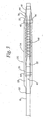
- Figure 7 is a side profile section showing a balloon expandable stent delivery and deployment assembly, with the stent crimped to delivery diameter onto the balloon, the underlying tube component and the catheter, and also having a pull-back wire 62 attached to the sheath of the stent securement means by means of a band or collar 64.
- sheath 28 is slidable axially along the shaft 14 and is connected to a retracting wire 62 such that sheath 28 may be proximally advanced.
- the other elements of the Figure are similar to those of Figure 2.
Abstract

Description
Claims (5)
- An apparatus for delivery and deployment of an expandable stent within a vessel, the apparatus comprising:a) a catheter having a proximal end, a middle portion, a distal end and a catheter shaft;b) an expandable stent, expandable from a delivery diameter to a deployment diameter, the stent being coaxially mounted on the distal end of the catheter for expansion thereof;c) securement means coaxially mounted on the catheter near its distal end, distal the middle portion, and over the stent, said securement means comprising:i) a securement sheath having a proximal end, a distal end, an exterior surface and an interior surface, said securement sheath being slidable mounted on the catheter shaft and being constructed and arranged for proximal retraction along the catheter shaft to expose the stent, the securement sheath having a plurality of flexibility enhancing elements, the plurality of flexibility enhancing elements being dispersed substantially throughout the securement sheath.
- The apparatus of claim 1, wherein the securement means further comprises, a distal cuff having a proximal end, a distal end, an exterior surface and an interior surface, said distal cuff being mounted near the distal end of the stent and being constructed and arranged to be in contact with the securement sheath at the distal end of the securement sheath until retraction thereof.
- The apparatus of claims 1-2, wherein the flexibility enhancing elements comprise a plurality of holes in the securement sheath.
- The apparatus of claims 1-2, wherein the flexibility enhancing elements comprise a plurality of dimples in the securement sheath.
- The apparatus of claims 1-2, wherein the flexibility enhancing elements comprise a plurality of radial indentations in the securement sheath.
Applications Claiming Priority (3)
| Application Number | Priority Date | Filing Date | Title |
|---|---|---|---|
| US332914 | 1999-06-14 | ||
| US09/332,914 US6168617B1 (en) | 1999-06-14 | 1999-06-14 | Stent delivery system |
| EP00939888A EP1185217B1 (en) | 1999-06-14 | 2000-06-14 | Stent delivery system |
Related Parent Applications (2)
| Application Number | Title | Priority Date | Filing Date |
|---|---|---|---|
| EP00939888.4 Division | 2000-06-14 | ||
| EP00939888A Division EP1185217B1 (en) | 1999-06-14 | 2000-06-14 | Stent delivery system |
Publications (2)
| Publication Number | Publication Date |
|---|---|
| EP1537837A2 true EP1537837A2 (en) | 2005-06-08 |
| EP1537837A3 EP1537837A3 (en) | 2007-07-25 |
Family
ID=23300411
Family Applications (2)
| Application Number | Title | Priority Date | Filing Date |
|---|---|---|---|
| EP00939888A Expired - Lifetime EP1185217B1 (en) | 1999-06-14 | 2000-06-14 | Stent delivery system |
| EP05004256A Withdrawn EP1537837A3 (en) | 1999-06-14 | 2000-06-14 | Stent delivery system |
Family Applications Before (1)
| Application Number | Title | Priority Date | Filing Date |
|---|---|---|---|
| EP00939888A Expired - Lifetime EP1185217B1 (en) | 1999-06-14 | 2000-06-14 | Stent delivery system |
Country Status (5)
| Country | Link |
|---|---|
| US (2) | US6168617B1 (en) |
| EP (2) | EP1185217B1 (en) |
| AT (1) | ATE301442T1 (en) |
| DE (1) | DE60021881T2 (en) |
| WO (1) | WO2000076425A1 (en) |
Cited By (1)
| Publication number | Priority date | Publication date | Assignee | Title |
|---|---|---|---|---|
| EP1272126B1 (en) * | 2000-04-14 | 2008-03-26 | Boston Scientific Scimed, Inc. | Stent securement system |
Families Citing this family (179)
| Publication number | Priority date | Publication date | Assignee | Title |
|---|---|---|---|---|
| US5749848A (en) * | 1995-11-13 | 1998-05-12 | Cardiovascular Imaging Systems, Inc. | Catheter system having imaging, balloon angioplasty, and stent deployment capabilities, and method of use for guided stent deployment |
| US6776792B1 (en) * | 1997-04-24 | 2004-08-17 | Advanced Cardiovascular Systems Inc. | Coated endovascular stent |
| US7101597B2 (en) | 1997-09-10 | 2006-09-05 | Boston Scientific Scimed, Inc. | Medical devices made from polymer blends containing low melting temperature liquid crystal polymers |
| ES2237168T3 (en) * | 1998-09-30 | 2005-07-16 | Bard Peripheral Vascular, Inc. | SUPPLY MECHANISM FOR IMPLANTABLE STENT. |
| US6478814B2 (en) * | 1999-06-14 | 2002-11-12 | Scimed Life Systems, Inc. | Stent securement sleeves and optional coatings and methods of use |
| US6790228B2 (en) * | 1999-12-23 | 2004-09-14 | Advanced Cardiovascular Systems, Inc. | Coating for implantable devices and a method of forming the same |
| US7758624B2 (en) * | 2000-11-13 | 2010-07-20 | C. R. Bard, Inc. | Implant delivery device |
| US6331184B1 (en) * | 1999-12-10 | 2001-12-18 | Scimed Life Systems, Inc. | Detachable covering for an implantable medical device |
| US6602280B2 (en) | 2000-02-02 | 2003-08-05 | Trivascular, Inc. | Delivery system and method for expandable intracorporeal device |
| US6264683B1 (en) | 2000-03-17 | 2001-07-24 | Advanced Cardiovascular Systems, Inc. | Stent delivery catheter with bumpers for improved retention of balloon expandable stents |
| US6432130B1 (en) * | 2000-04-20 | 2002-08-13 | Scimed Life Systems, Inc. | Fully sheathed balloon expandable stent delivery system |
| US6613067B1 (en) * | 2000-06-06 | 2003-09-02 | Scimed Life Systems, Inc. | Balloon protector |
| US6773446B1 (en) | 2000-08-02 | 2004-08-10 | Cordis Corporation | Delivery apparatus for a self-expanding stent |
| US6447521B1 (en) | 2000-09-15 | 2002-09-10 | Advanced Cardiovascular Systems, Inc. | Foamed inner member cover stent retention and method of use |
| US20030050684A1 (en) * | 2001-09-10 | 2003-03-13 | Abrams Robert M. | Internal restraint for delivery of self-expanding stents |
| JP2004512867A (en) * | 2000-10-05 | 2004-04-30 | ボストン サイエンティフィック リミテッド | Body socks for stent delivery catheters |
| US6783793B1 (en) * | 2000-10-26 | 2004-08-31 | Advanced Cardiovascular Systems, Inc. | Selective coating of medical devices |
| US6843802B1 (en) * | 2000-11-16 | 2005-01-18 | Cordis Corporation | Delivery apparatus for a self expanding retractable stent |
| US20020072789A1 (en) * | 2000-12-12 | 2002-06-13 | Hackett Steven S. | Soc lubricant filler port |
| US20020095203A1 (en) * | 2001-01-18 | 2002-07-18 | Intra Therapeutics, Inc. | Catheter system with spacer member |
| US6547813B2 (en) * | 2001-03-23 | 2003-04-15 | Medtronic Ave, Inc. | Stent delivery catheter with folded sleeve and method of making same |
| US6620191B1 (en) | 2001-03-27 | 2003-09-16 | Advanced Cardiovascular Systems, Inc. | System for releasably securing a stent on a catheter assembly and method of use |
| US6761733B2 (en) * | 2001-04-11 | 2004-07-13 | Trivascular, Inc. | Delivery system and method for bifurcated endovascular graft |
| US6733521B2 (en) | 2001-04-11 | 2004-05-11 | Trivascular, Inc. | Delivery system and method for endovascular graft |
| US6660031B2 (en) | 2001-04-11 | 2003-12-09 | Scimed Life Systems, Inc. | Multi-length delivery system |
| US20040138734A1 (en) * | 2001-04-11 | 2004-07-15 | Trivascular, Inc. | Delivery system and method for bifurcated graft |
| US20050021123A1 (en) * | 2001-04-30 | 2005-01-27 | Jurgen Dorn | Variable speed self-expanding stent delivery system and luer locking connector |
| NL1018881C2 (en) * | 2001-05-08 | 2002-11-25 | Blue Medical Devices B V | Balloon catheter for dilating vessels and lumina comprise inflatable balloon with ends attached to it's catheter tube |
| NL1018018C2 (en) * | 2001-05-08 | 2002-11-19 | Blue Medical Devices B V | Balloon catheter and method for manufacturing thereof. |
| US6666880B1 (en) | 2001-06-19 | 2003-12-23 | Advised Cardiovascular Systems, Inc. | Method and system for securing a coated stent to a balloon catheter |
| US6565659B1 (en) * | 2001-06-28 | 2003-05-20 | Advanced Cardiovascular Systems, Inc. | Stent mounting assembly and a method of using the same to coat a stent |
| WO2003003944A2 (en) | 2001-07-06 | 2003-01-16 | Angiomed Gmbh & Co. Medizintechnik Kg | Delivery system having a rapid pusher assembly for self-expanding stent, and stent exchange configuration |
| US6645238B2 (en) * | 2001-07-09 | 2003-11-11 | Scimed Life Systems, Inc. | Skids stent delivery system |
| US20030032999A1 (en) * | 2001-08-07 | 2003-02-13 | Medtronic Ave, Inc. | Balloon stent assembly system and method |
| US6979346B1 (en) | 2001-08-08 | 2005-12-27 | Advanced Cardiovascular Systems, Inc. | System and method for improved stent retention |
| US20030050648A1 (en) | 2001-09-11 | 2003-03-13 | Spiration, Inc. | Removable lung reduction devices, systems, and methods |
| GB0123633D0 (en) | 2001-10-02 | 2001-11-21 | Angiomed Ag | Stent delivery system |
| US6770101B2 (en) | 2001-10-09 | 2004-08-03 | Scimed Life Systems, Inc. | Prostatic stent and delivery system |
| US6592594B2 (en) * | 2001-10-25 | 2003-07-15 | Spiration, Inc. | Bronchial obstruction device deployment system and method |
| US20100016943A1 (en) | 2001-12-20 | 2010-01-21 | Trivascular2, Inc. | Method of delivering advanced endovascular graft |
| US6939368B2 (en) | 2002-01-17 | 2005-09-06 | Scimed Life Systems, Inc. | Delivery system for self expanding stents for use in bifurcated vessels |
| US6790224B2 (en) | 2002-02-04 | 2004-09-14 | Scimed Life Systems, Inc. | Medical devices |
| US6929637B2 (en) * | 2002-02-21 | 2005-08-16 | Spiration, Inc. | Device and method for intra-bronchial provision of a therapeutic agent |
| US7484006B2 (en) * | 2002-02-22 | 2009-01-27 | Bea Systems, Inc. | System and method for server network configuration and addressing |
| US6989024B2 (en) * | 2002-02-28 | 2006-01-24 | Counter Clockwise, Inc. | Guidewire loaded stent for delivery through a catheter |
| US20030181922A1 (en) | 2002-03-20 | 2003-09-25 | Spiration, Inc. | Removable anchored lung volume reduction devices and methods |
| US20030216769A1 (en) | 2002-05-17 | 2003-11-20 | Dillard David H. | Removable anchored lung volume reduction devices and methods |
| US20030187493A1 (en) * | 2002-03-29 | 2003-10-02 | Todd Campbell | Coated stent with protective assembly and method of using same |
| US6830575B2 (en) * | 2002-05-08 | 2004-12-14 | Scimed Life Systems, Inc. | Method and device for providing full protection to a stent |
| EP1388328A1 (en) * | 2002-08-07 | 2004-02-11 | Abbott Laboratories Vascular Enterprises Limited | Apparatus for delivering and deployment of an expandable stent within a blood vessel |
| US7037319B2 (en) * | 2002-10-15 | 2006-05-02 | Scimed Life Systems, Inc. | Nanotube paper-based medical device |
| US8568467B2 (en) | 2003-01-15 | 2013-10-29 | Angiomed Gmbh & Co. Medizintechnik Kg | Trans-luminal surgical device |
| EP1596761B1 (en) * | 2003-02-14 | 2015-06-17 | Salviac Limited | Stent delivery and deployment system |
| US7100616B2 (en) * | 2003-04-08 | 2006-09-05 | Spiration, Inc. | Bronchoscopic lung volume reduction method |
| US7473271B2 (en) * | 2003-04-11 | 2009-01-06 | Boston Scientific Scimed, Inc. | Stent delivery system with securement and deployment accuracy |
| US20040267348A1 (en) * | 2003-04-11 | 2004-12-30 | Gunderson Richard C. | Medical device delivery systems |
| US7731747B2 (en) * | 2003-04-14 | 2010-06-08 | Tryton Medical, Inc. | Vascular bifurcation prosthesis with multiple thin fronds |
| US7481834B2 (en) | 2003-04-14 | 2009-01-27 | Tryton Medical, Inc. | Stent for placement at luminal os |
| US7717953B2 (en) * | 2004-10-13 | 2010-05-18 | Tryton Medical, Inc. | Delivery system for placement of prosthesis at luminal OS |
| US8083791B2 (en) * | 2003-04-14 | 2011-12-27 | Tryton Medical, Inc. | Method of treating a lumenal bifurcation |
| US7972372B2 (en) * | 2003-04-14 | 2011-07-05 | Tryton Medical, Inc. | Kit for treating vascular bifurcations |
| US7758630B2 (en) * | 2003-04-14 | 2010-07-20 | Tryton Medical, Inc. | Helical ostium support for treating vascular bifurcations |
| US8109987B2 (en) * | 2003-04-14 | 2012-02-07 | Tryton Medical, Inc. | Method of treating a lumenal bifurcation |
| US8318078B2 (en) * | 2003-06-23 | 2012-11-27 | Boston Scientific Scimed, Inc. | Asymmetric stent delivery system with proximal edge protection and method of manufacture thereof |
| US7470282B2 (en) * | 2003-06-30 | 2008-12-30 | Boston Scientific Scimed, Inc. | Stent grip and system for use therewith |
| US7533671B2 (en) | 2003-08-08 | 2009-05-19 | Spiration, Inc. | Bronchoscopic repair of air leaks in a lung |
| US7867268B2 (en) * | 2003-09-24 | 2011-01-11 | Boston Scientific Scimed, Inc. | Stent delivery system for self-expanding stent |
| US7198675B2 (en) * | 2003-09-30 | 2007-04-03 | Advanced Cardiovascular Systems | Stent mandrel fixture and method for selectively coating surfaces of a stent |
| US20050143803A1 (en) * | 2003-12-24 | 2005-06-30 | Medtronic Vascular, Inc. | Protective sheath for drug coated stent |
| US20050154441A1 (en) * | 2004-01-14 | 2005-07-14 | Cook Incorporated | Introducer |
| US20050288481A1 (en) * | 2004-04-30 | 2005-12-29 | Desnoyer Jessica R | Design of poly(ester amides) for the control of agent-release from polymeric compositions |
| US20050265960A1 (en) * | 2004-05-26 | 2005-12-01 | Pacetti Stephen D | Polymers containing poly(ester amides) and agents for use with medical articles and methods of fabricating the same |
| US7353946B2 (en) | 2004-05-11 | 2008-04-08 | Medtronic Vascular, Inc. | Protective packaging assembly for medical devices and method of using same |
| US20050278010A1 (en) * | 2004-05-27 | 2005-12-15 | Scimed Life Systems, Inc. | Stent delivery system with imaging capability |
| US7648727B2 (en) * | 2004-08-26 | 2010-01-19 | Advanced Cardiovascular Systems, Inc. | Methods for manufacturing a coated stent-balloon assembly |
| JP4713589B2 (en) * | 2004-09-01 | 2011-06-29 | クック インコーポレイテッド | Delivery system for hydration of intraluminal medical devices |
| US20060064064A1 (en) * | 2004-09-17 | 2006-03-23 | Jang G D | Two-step/dual-diameter balloon angioplasty catheter for bifurcation and side-branch vascular anatomy |
| US7658757B2 (en) * | 2004-10-08 | 2010-02-09 | Boston Scientific Scimed, Inc. | Endoprosthesis delivery system |
| US20080188803A1 (en) * | 2005-02-03 | 2008-08-07 | Jang G David | Triple-profile balloon catheter |
| US20060216431A1 (en) * | 2005-03-28 | 2006-09-28 | Kerrigan Cameron K | Electrostatic abluminal coating of a stent crimped on a balloon catheter |
| US7740652B2 (en) | 2005-03-30 | 2010-06-22 | Boston Scientific Scimed, Inc. | Catheter |
| US8652193B2 (en) | 2005-05-09 | 2014-02-18 | Angiomed Gmbh & Co. Medizintechnik Kg | Implant delivery device |
| US20060265040A1 (en) * | 2005-05-17 | 2006-11-23 | Medtronic Vascular, Inc. | Stent delivery and retention apparatus |
| US8435279B2 (en) | 2005-06-14 | 2013-05-07 | Advanced Cardiovascular Systems, Inc. | Delivery system for a device such as a stent |
| JP2009504345A (en) | 2005-08-17 | 2009-02-05 | シー・アール・バード・インコーポレーテッド | Variable speed stent delivery system |
| US8968379B2 (en) * | 2005-09-02 | 2015-03-03 | Medtronic Vascular, Inc. | Stent delivery system with multiple evenly spaced pullwires |
| US8292827B2 (en) | 2005-12-12 | 2012-10-23 | Boston Scientific Scimed, Inc. | Micromachined medical devices |
| US7867547B2 (en) | 2005-12-19 | 2011-01-11 | Advanced Cardiovascular Systems, Inc. | Selectively coating luminal surfaces of stents |
| WO2007076114A2 (en) * | 2005-12-23 | 2007-07-05 | Cook Incorporated | Prosthesis deployment system |
| WO2007084370A1 (en) * | 2006-01-13 | 2007-07-26 | C.R. Bard, Inc. | Stent delivery system |
| US11026822B2 (en) | 2006-01-13 | 2021-06-08 | C. R. Bard, Inc. | Stent delivery system |
| US20070203563A1 (en) * | 2006-02-13 | 2007-08-30 | Stephen Hebert | System for delivering a stent |
| US8518098B2 (en) | 2006-02-21 | 2013-08-27 | Cook Medical Technologies Llc | Split sheath deployment system |
| US7473232B2 (en) * | 2006-02-24 | 2009-01-06 | Boston Scientific Scimed, Inc. | Obtaining a tissue sample |
| US8414632B2 (en) | 2006-03-06 | 2013-04-09 | Boston Scientific Scimed, Inc. | Adjustable catheter tip |
| US20070208405A1 (en) * | 2006-03-06 | 2007-09-06 | Boston Scientific Scimed, Inc. | Stent delivery catheter |
| US7691151B2 (en) * | 2006-03-31 | 2010-04-06 | Spiration, Inc. | Articulable Anchor |
| US8403977B2 (en) * | 2006-05-04 | 2013-03-26 | Cook Medical Technologies Llc | Self-orienting delivery system |
| US8069814B2 (en) | 2006-05-04 | 2011-12-06 | Advanced Cardiovascular Systems, Inc. | Stent support devices |
| US20080097620A1 (en) | 2006-05-26 | 2008-04-24 | Nanyang Technological University | Implantable article, method of forming same and method for reducing thrombogenicity |
| US8603530B2 (en) * | 2006-06-14 | 2013-12-10 | Abbott Cardiovascular Systems Inc. | Nanoshell therapy |
| US8048448B2 (en) | 2006-06-15 | 2011-11-01 | Abbott Cardiovascular Systems Inc. | Nanoshells for drug delivery |
| US8118853B2 (en) * | 2006-06-19 | 2012-02-21 | Cook Medical Technologies Llc | Prosthesis delivery and deployment device |
| US8017237B2 (en) * | 2006-06-23 | 2011-09-13 | Abbott Cardiovascular Systems, Inc. | Nanoshells on polymers |
| US7909844B2 (en) * | 2006-07-31 | 2011-03-22 | Boston Scientific Scimed, Inc. | Catheters having actuatable lumen assemblies |
| GB0615658D0 (en) * | 2006-08-07 | 2006-09-13 | Angiomed Ag | Hand-held actuator device |
| US9339632B2 (en) | 2006-09-27 | 2016-05-17 | Boston Scientific Scimed, Inc. | Catheter shaft designs |
| ES2382364T3 (en) * | 2006-09-28 | 2012-06-07 | St George Medical Inc | Thoracic aortic aneurysm repair device. |
| US8216298B2 (en) * | 2007-01-05 | 2012-07-10 | Medtronic Vascular, Inc. | Branch vessel graft method and delivery system |
| US20080255654A1 (en) * | 2007-03-22 | 2008-10-16 | Bay Street Medical | System for delivering a stent |
| US7981148B2 (en) * | 2007-05-16 | 2011-07-19 | Boston Scientific Scimed, Inc. | Stent delivery catheter |
| US20080294230A1 (en) * | 2007-05-24 | 2008-11-27 | Cook Incorporated | Apparatus and methods for deploying self-expanding stents |
| US20080300667A1 (en) * | 2007-05-31 | 2008-12-04 | Bay Street Medical | System for delivering a stent |
| US8048441B2 (en) | 2007-06-25 | 2011-11-01 | Abbott Cardiovascular Systems, Inc. | Nanobead releasing medical devices |
| US9216101B2 (en) | 2007-07-10 | 2015-12-22 | Boston Scientific Scime, Inc. | Dual taper stent protector |
| GB0713497D0 (en) | 2007-07-11 | 2007-08-22 | Angiomed Ag | Device for catheter sheath retraction |
| US8370032B2 (en) * | 2007-07-12 | 2013-02-05 | Toyota Motor Engineering & Manufacturing North America, Inc. | Systems and methods for shift control for vehicular transmission |
| US9119742B2 (en) * | 2007-07-16 | 2015-09-01 | Cook Medical Technologies Llc | Prosthesis delivery and deployment device |
| US9144508B2 (en) * | 2007-07-19 | 2015-09-29 | Back Bay Medical Inc. | Radially expandable stent |
| US20090093876A1 (en) * | 2007-08-31 | 2009-04-09 | Edwards Lifesciences Corporation | Recoil inhibitor for prosthetic valve |
| US8066755B2 (en) * | 2007-09-26 | 2011-11-29 | Trivascular, Inc. | System and method of pivoted stent deployment |
| US20090082841A1 (en) * | 2007-09-26 | 2009-03-26 | Boston Scientific Corporation | Apparatus for securing stent barbs |
| US8663309B2 (en) | 2007-09-26 | 2014-03-04 | Trivascular, Inc. | Asymmetric stent apparatus and method |
| US8226701B2 (en) | 2007-09-26 | 2012-07-24 | Trivascular, Inc. | Stent and delivery system for deployment thereof |
| CN101917929A (en) | 2007-10-04 | 2010-12-15 | 特里瓦斯库拉尔公司 | Modular vascular graft for low profile percutaneous delivery |
| EP2641572B1 (en) | 2007-10-12 | 2019-07-24 | Spiration Inc. | Valve loader method, system, and apparatus |
| US8043301B2 (en) * | 2007-10-12 | 2011-10-25 | Spiration, Inc. | Valve loader method, system, and apparatus |
| US8083789B2 (en) * | 2007-11-16 | 2011-12-27 | Trivascular, Inc. | Securement assembly and method for expandable endovascular device |
| US8328861B2 (en) | 2007-11-16 | 2012-12-11 | Trivascular, Inc. | Delivery system and method for bifurcated graft |
| US20090157048A1 (en) * | 2007-12-18 | 2009-06-18 | Boston Scientific Scimed, Inc. | Spiral cut hypotube |
| US20100331958A1 (en) * | 2007-12-20 | 2010-12-30 | Trivascular, Inc. | Hinged endovascular device |
| US8460213B2 (en) | 2008-01-03 | 2013-06-11 | Boston Scientific Scimed, Inc. | Cut tubular members for a medical device and methods for making and using the same |
| US20090281617A1 (en) * | 2008-05-10 | 2009-11-12 | Orbusneich Medical, Inc. | Sleeves for Positioning a Stent on a Delivery Balloon Catheter System |
| US9750625B2 (en) | 2008-06-11 | 2017-09-05 | C.R. Bard, Inc. | Catheter delivery device |
| GB0810749D0 (en) | 2008-06-11 | 2008-07-16 | Angiomed Ag | Catherter delivery device |
| US8206636B2 (en) | 2008-06-20 | 2012-06-26 | Amaranth Medical Pte. | Stent fabrication via tubular casting processes |
| US8206635B2 (en) | 2008-06-20 | 2012-06-26 | Amaranth Medical Pte. | Stent fabrication via tubular casting processes |
| US10898620B2 (en) | 2008-06-20 | 2021-01-26 | Razmodics Llc | Composite stent having multi-axial flexibility and method of manufacture thereof |
| US9572693B2 (en) * | 2009-05-14 | 2017-02-21 | Orbusneich Medical, Inc. | Self-expanding stent with polygon transition zone |
| US8366763B2 (en) | 2009-07-02 | 2013-02-05 | Tryton Medical, Inc. | Ostium support for treating vascular bifurcations |
| JP5662324B2 (en) * | 2009-09-16 | 2015-01-28 | テルモ株式会社 | Stent delivery system |
| US8409240B2 (en) * | 2009-11-25 | 2013-04-02 | Boston Scientific Scimed, Inc. | Embolic protection device |
| US20110218609A1 (en) * | 2010-02-10 | 2011-09-08 | Trivascular, Inc. | Fill tube manifold and delivery methods for endovascular graft |
| US8465541B2 (en) * | 2010-04-19 | 2013-06-18 | Medtronic, Inc. | Transcatheter prosthetic heart valve delivery system and method with expandable stability tube |
| US9795771B2 (en) * | 2010-10-19 | 2017-10-24 | Warsaw Orthopedic, Inc. | Expandable spinal access instruments and methods of use |
| GB201017834D0 (en) | 2010-10-21 | 2010-12-01 | Angiomed Ag | System to deliver a bodily implant |
| WO2012068389A1 (en) | 2010-11-17 | 2012-05-24 | Boston Scientific Scimed, Inc. | Stent delivery system |
| CN103298433B (en) | 2010-11-17 | 2016-03-16 | 波士顿科学西美德公司 | Stent delivery system and the Lock Part for using together with stent delivery system |
| CN103298432B (en) | 2010-11-17 | 2016-03-02 | 波士顿科学西美德公司 | stent delivery system |
| WO2012071542A2 (en) | 2010-11-24 | 2012-05-31 | Tryton Medical, Inc. | Support for treating vascular bifurcations |
| US20120197377A1 (en) * | 2011-02-01 | 2012-08-02 | Micrus Endovascular Corporation | Wire with compliant sheath |
| JP6320914B2 (en) | 2011-04-29 | 2018-05-09 | エバスク・ニューロバスキュラー・リミテッド・パートナーシップEvasc Neurovascular Limited Partnership | Endovascular prostheses and delivery devices |
| US8795241B2 (en) | 2011-05-13 | 2014-08-05 | Spiration, Inc. | Deployment catheter |
| US9101507B2 (en) | 2011-05-18 | 2015-08-11 | Ralph F. Caselnova | Apparatus and method for proximal-to-distal endoluminal stent deployment |
| WO2013067168A1 (en) | 2011-11-02 | 2013-05-10 | Boston Scientific Scimed, Inc. | Stent delivery systems and methods for use |
| WO2013120082A1 (en) | 2012-02-10 | 2013-08-15 | Kassab Ghassan S | Methods and uses of biological tissues for various stent and other medical applications |
| US8992595B2 (en) | 2012-04-04 | 2015-03-31 | Trivascular, Inc. | Durable stent graft with tapered struts and stable delivery methods and devices |
| US9498363B2 (en) | 2012-04-06 | 2016-11-22 | Trivascular, Inc. | Delivery catheter for endovascular device |
| WO2013162724A1 (en) | 2012-04-26 | 2013-10-31 | Tryton Medical, Inc. | Support for treating vascular bifurcations |
| EP2953580A2 (en) | 2013-02-11 | 2015-12-16 | Cook Medical Technologies LLC | Expandable support frame and medical device |
| US20140228821A1 (en) * | 2013-02-13 | 2014-08-14 | Conceptus Inc. | Delivery catheter with controlled flexibility |
| US10390943B2 (en) | 2014-03-17 | 2019-08-27 | Evalve, Inc. | Double orifice device for transcatheter mitral valve replacement |
| US10016292B2 (en) | 2014-04-18 | 2018-07-10 | Covidien Lp | Stent delivery system |
| US10159587B2 (en) | 2015-01-16 | 2018-12-25 | Boston Scientific Scimed, Inc. | Medical device delivery system with force reduction member |
| WO2016160905A1 (en) * | 2015-03-31 | 2016-10-06 | Transmed7, Llc | Devices and methods for vascular interventions |
| BR102015011376B1 (en) | 2015-05-18 | 2023-04-04 | Murilo Pundek Rocha | IMPLANTABLE ARTIFICIAL BRONCHI |
| US11351048B2 (en) | 2015-11-16 | 2022-06-07 | Boston Scientific Scimed, Inc. | Stent delivery systems with a reinforced deployment sheath |
| US10792477B2 (en) | 2016-02-08 | 2020-10-06 | Orbusneich Medical Pte. Ltd. | Drug eluting balloon |
| US20210196932A1 (en) | 2016-02-08 | 2021-07-01 | Orbusneich Medical, Inc. | Drug Eluting Balloon |
| EP3419568B1 (en) | 2016-02-26 | 2021-09-08 | Boston Scientific Scimed, Inc. | Stent delivery systems with a reduced profile |
| US10363138B2 (en) | 2016-11-09 | 2019-07-30 | Evalve, Inc. | Devices for adjusting the curvature of cardiac valve structures |
| US10426616B2 (en) * | 2016-11-17 | 2019-10-01 | Evalve, Inc. | Cardiac implant delivery system |
| US10835401B2 (en) | 2016-12-29 | 2020-11-17 | Boston Scientific Scimed, Inc. | Hydration delivery system for stents |
| US11013627B2 (en) | 2018-01-10 | 2021-05-25 | Boston Scientific Scimed, Inc. | Stent delivery system with displaceable deployment mechanism |
| WO2019209745A1 (en) | 2018-04-23 | 2019-10-31 | Boston Scientific Scimed, Inc. | Stent with selectively covered region |
| JP7399971B2 (en) | 2019-02-13 | 2023-12-18 | ボストン サイエンティフィック サイムド,インコーポレイテッド | stent delivery system |
| USD902407S1 (en) | 2019-11-19 | 2020-11-17 | Pulmair Medical, Inc. | Implantable artificial bronchus |
| USD954953S1 (en) | 2020-11-03 | 2022-06-14 | Pulmair Medical, Inc. | Implantable artificial bronchus |
| USD1014758S1 (en) | 2023-04-19 | 2024-02-13 | Pulmair Medical, Inc. | Implantable artificial bronchus |
Citations (8)
| Publication number | Priority date | Publication date | Assignee | Title |
|---|---|---|---|---|
| US4733665A (en) | 1985-11-07 | 1988-03-29 | Expandable Grafts Partnership | Expandable intraluminal graft, and method and apparatus for implanting an expandable intraluminal graft |
| US4740207A (en) | 1986-09-10 | 1988-04-26 | Kreamer Jeffry W | Intralumenal graft |
| US5007926A (en) | 1989-02-24 | 1991-04-16 | The Trustees Of The University Of Pennsylvania | Expandable transluminally implantable tubular prosthesis |
| US5026377A (en) | 1989-07-13 | 1991-06-25 | American Medical Systems, Inc. | Stent placement instrument and method |
| US5242399A (en) | 1990-04-25 | 1993-09-07 | Advanced Cardiovascular Systems, Inc. | Method and system for stent delivery |
| US5344426A (en) | 1990-04-25 | 1994-09-06 | Advanced Cardiovascular Systems, Inc. | Method and system for stent delivery |
| US5415664A (en) | 1994-03-30 | 1995-05-16 | Corvita Corporation | Method and apparatus for introducing a stent or a stent-graft |
| US5453090A (en) | 1994-03-01 | 1995-09-26 | Cordis Corporation | Method of stent delivery through an elongate softenable sheath |
Family Cites Families (36)
| Publication number | Priority date | Publication date | Assignee | Title |
|---|---|---|---|---|
| US4950227A (en) | 1988-11-07 | 1990-08-21 | Boston Scientific Corporation | Stent delivery system |
| US5147302A (en) | 1989-04-21 | 1992-09-15 | Scimed Life Systems, Inc. | Method of shaping a balloon of a balloon catheter |
| US5108416A (en) | 1990-02-13 | 1992-04-28 | C. R. Bard, Inc. | Stent introducer system |
| US5158548A (en) | 1990-04-25 | 1992-10-27 | Advanced Cardiovascular Systems, Inc. | Method and system for stent delivery |
| CA2060067A1 (en) * | 1991-01-28 | 1992-07-29 | Lilip Lau | Stent delivery system |
| EP0572624A4 (en) | 1991-12-18 | 1994-07-06 | Scimed Life Systems Inc | Lubricous polymer network |
| US5201757A (en) | 1992-04-03 | 1993-04-13 | Schneider (Usa) Inc. | Medial region deployment of radially self-expanding stents |
| US5290295A (en) | 1992-07-15 | 1994-03-01 | Querals & Fine, Inc. | Insertion tool for an intraluminal graft procedure |
| US5360401A (en) | 1993-02-18 | 1994-11-01 | Advanced Cardiovascular Systems, Inc. | Catheter for stent delivery |
| US5354310A (en) * | 1993-03-22 | 1994-10-11 | Cordis Corporation | Expandable temporary graft |
| US5458615A (en) | 1993-07-06 | 1995-10-17 | Advanced Cardiovascular Systems, Inc. | Stent delivery system |
| US5545209A (en) | 1993-09-30 | 1996-08-13 | Texas Petrodet, Inc. | Controlled deployment of a medical device |
| US5445646A (en) | 1993-10-22 | 1995-08-29 | Scimed Lifesystems, Inc. | Single layer hydraulic sheath stent delivery apparatus and method |
| ATE288298T1 (en) * | 1993-10-22 | 2005-02-15 | Scimed Life Systems Inc | STENT DELIVERY APPARATUS AND METHOD |
| US5571135A (en) | 1993-10-22 | 1996-11-05 | Scimed Life Systems Inc. | Stent delivery apparatus and method |
| US5403341A (en) | 1994-01-24 | 1995-04-04 | Solar; Ronald J. | Parallel flow endovascular stent and deployment apparatus therefore |
| US5733303A (en) | 1994-03-17 | 1998-03-31 | Medinol Ltd. | Flexible expandable stent |
| US5458605A (en) | 1994-04-04 | 1995-10-17 | Advanced Cardiovascular Systems, Inc. | Coiled reinforced retractable sleeve for stent delivery catheter |
| NL9500284A (en) | 1994-10-20 | 1996-06-03 | Cordis Europ | Catheter for stent implantation. |
| US5628755A (en) * | 1995-02-20 | 1997-05-13 | Schneider (Europe) A.G. | Balloon catheter and stent delivery system |
| CA2163708C (en) * | 1994-12-07 | 2007-08-07 | Robert E. Fischell | Integrated dual-function catheter system for balloon angioplasty and stent delivery |
| US5647857A (en) * | 1995-03-16 | 1997-07-15 | Endotex Interventional Systems, Inc. | Protective intraluminal sheath |
| US5571168A (en) * | 1995-04-05 | 1996-11-05 | Scimed Lifesystems Inc | Pull back stent delivery system |
| CA2218072A1 (en) * | 1995-04-14 | 1996-10-17 | Schneider (Usa) Inc. | Rolling membrane stent delivery device |
| US5534007A (en) | 1995-05-18 | 1996-07-09 | Scimed Life Systems, Inc. | Stent deployment catheter with collapsible sheath |
| US5517135A (en) | 1995-07-26 | 1996-05-14 | Xilinx, Inc. | Bidirectional tristate buffer with default input |
| US5935135A (en) * | 1995-09-29 | 1999-08-10 | United States Surgical Corporation | Balloon delivery system for deploying stents |
| US5830217A (en) * | 1996-08-09 | 1998-11-03 | Thomas J. Fogarty | Soluble fixation device and method for stent delivery catheters |
| US5800517A (en) * | 1996-08-19 | 1998-09-01 | Scimed Life Systems, Inc. | Stent delivery system with storage sleeve |
| WO1998007390A1 (en) | 1996-08-23 | 1998-02-26 | Scimed Life Systems, Inc. | Stent delivery system having stent securement apparatus |
| US5944726A (en) * | 1996-08-23 | 1999-08-31 | Scimed Life Systems, Inc. | Stent delivery system having stent securement means |
| US5980530A (en) | 1996-08-23 | 1999-11-09 | Scimed Life Systems Inc | Stent delivery system |
| DK176341B1 (en) | 1996-09-06 | 2007-08-27 | Cook William Europ | Aggregate for transluminal insertion of a tubular stent and an endovascular graft device |
| US5772669A (en) * | 1996-09-27 | 1998-06-30 | Scimed Life Systems, Inc. | Stent deployment catheter with retractable sheath |
| US5843090A (en) * | 1996-11-05 | 1998-12-01 | Schneider (Usa) Inc. | Stent delivery device |
| US5735859A (en) * | 1997-02-14 | 1998-04-07 | Cathco, Inc. | Distally attachable and releasable sheath for a stent delivery system |
-
1999
- 1999-06-14 US US09/332,914 patent/US6168617B1/en not_active Expired - Lifetime
-
2000
- 2000-06-14 EP EP00939888A patent/EP1185217B1/en not_active Expired - Lifetime
- 2000-06-14 EP EP05004256A patent/EP1537837A3/en not_active Withdrawn
- 2000-06-14 AT AT00939888T patent/ATE301442T1/en not_active IP Right Cessation
- 2000-06-14 WO PCT/US2000/016440 patent/WO2000076425A1/en active IP Right Grant
- 2000-06-14 DE DE60021881T patent/DE60021881T2/en not_active Expired - Lifetime
-
2001
- 2001-01-02 US US09/753,533 patent/US6626934B2/en not_active Expired - Fee Related
Patent Citations (10)
| Publication number | Priority date | Publication date | Assignee | Title |
|---|---|---|---|---|
| US4733665A (en) | 1985-11-07 | 1988-03-29 | Expandable Grafts Partnership | Expandable intraluminal graft, and method and apparatus for implanting an expandable intraluminal graft |
| US4733665B1 (en) | 1985-11-07 | 1994-01-11 | Expandable Grafts Partnership | Expandable intraluminal graft,and method and apparatus for implanting an expandable intraluminal graft |
| US4733665C2 (en) | 1985-11-07 | 2002-01-29 | Expandable Grafts Partnership | Expandable intraluminal graft and method and apparatus for implanting an expandable intraluminal graft |
| US4740207A (en) | 1986-09-10 | 1988-04-26 | Kreamer Jeffry W | Intralumenal graft |
| US5007926A (en) | 1989-02-24 | 1991-04-16 | The Trustees Of The University Of Pennsylvania | Expandable transluminally implantable tubular prosthesis |
| US5026377A (en) | 1989-07-13 | 1991-06-25 | American Medical Systems, Inc. | Stent placement instrument and method |
| US5242399A (en) | 1990-04-25 | 1993-09-07 | Advanced Cardiovascular Systems, Inc. | Method and system for stent delivery |
| US5344426A (en) | 1990-04-25 | 1994-09-06 | Advanced Cardiovascular Systems, Inc. | Method and system for stent delivery |
| US5453090A (en) | 1994-03-01 | 1995-09-26 | Cordis Corporation | Method of stent delivery through an elongate softenable sheath |
| US5415664A (en) | 1994-03-30 | 1995-05-16 | Corvita Corporation | Method and apparatus for introducing a stent or a stent-graft |
Cited By (1)
| Publication number | Priority date | Publication date | Assignee | Title |
|---|---|---|---|---|
| EP1272126B1 (en) * | 2000-04-14 | 2008-03-26 | Boston Scientific Scimed, Inc. | Stent securement system |
Also Published As
| Publication number | Publication date |
|---|---|
| ATE301442T1 (en) | 2005-08-15 |
| WO2000076425A1 (en) | 2000-12-21 |
| US20010012959A1 (en) | 2001-08-09 |
| EP1537837A3 (en) | 2007-07-25 |
| US6168617B1 (en) | 2001-01-02 |
| DE60021881T2 (en) | 2006-04-06 |
| DE60021881D1 (en) | 2005-09-15 |
| EP1185217A1 (en) | 2002-03-13 |
| US6626934B2 (en) | 2003-09-30 |
| EP1185217B1 (en) | 2005-08-10 |
Similar Documents
| Publication | Publication Date | Title |
|---|---|---|
| EP1185217B1 (en) | Stent delivery system | |
| US8709062B2 (en) | Stent delivery system having stent securement apparatus | |
| US6802849B2 (en) | Stent delivery system | |
| US7201770B2 (en) | Everting balloon stent delivery system having tapered leading edge | |
| US6007543A (en) | Stent delivery system with stent securement means | |
| EP0932376B1 (en) | Stent delivery system | |
| JP4156371B2 (en) | Balloon catheter / stent delivery device with protrusions | |
| US5944726A (en) | Stent delivery system having stent securement means | |
| US6726714B2 (en) | Stent delivery system | |
| US6602226B1 (en) | Low-profile stent delivery system and apparatus | |
| EP1067886B1 (en) | Reversible-action endoprosthesis delivery device | |
| US6123712A (en) | Balloon catheter with stent securement means | |
| EP1347719B1 (en) | Expansion-assisting delivery system for self-expanding stent | |
| EP1861040B1 (en) | Rolling membrane with hydraulic recapture means for self expanding stent | |
| WO1998007390A1 (en) | Stent delivery system having stent securement apparatus | |
| US20030074044A1 (en) | Stent delivery system | |
| AU766834B2 (en) | Stent delivery system having stent securement apparatus |
Legal Events
| Date | Code | Title | Description |
|---|---|---|---|
| PUAI | Public reference made under article 153(3) epc to a published international application that has entered the european phase |
Free format text: ORIGINAL CODE: 0009012 |
|
| 17P | Request for examination filed |
Effective date: 20050304 |
|
| AC | Divisional application: reference to earlier application |
Ref document number: 1185217 Country of ref document: EP Kind code of ref document: P |
|
| AK | Designated contracting states |
Kind code of ref document: A2 Designated state(s): AT BE CH CY DE DK ES FI FR GB GR IE IT LI LU MC NL PT SE |
|
| PUAL | Search report despatched |
Free format text: ORIGINAL CODE: 0009013 |
|
| AK | Designated contracting states |
Kind code of ref document: A3 Designated state(s): AT BE CH CY DE DK ES FI FR GB GR IE IT LI LU MC NL PT SE |
|
| 17Q | First examination report despatched |
Effective date: 20071009 |
|
| AKX | Designation fees paid |
Designated state(s): AT BE CH CY DE DK ES FI FR GB GR IE IT LI LU MC NL PT SE |
|
| RIC1 | Information provided on ipc code assigned before grant |
Ipc: A61F 2/84 20060101ALN20090528BHEP Ipc: A61F 2/06 20060101AFI20090528BHEP |
|
| GRAP | Despatch of communication of intention to grant a patent |
Free format text: ORIGINAL CODE: EPIDOSNIGR1 |
|
| STAA | Information on the status of an ep patent application or granted ep patent |
Free format text: STATUS: THE APPLICATION IS DEEMED TO BE WITHDRAWN |
|
| 18D | Application deemed to be withdrawn |
Effective date: 20100511 |