EP1538524A2 - Scalable display - Google Patents
Scalable display Download PDFInfo
- Publication number
- EP1538524A2 EP1538524A2 EP04026924A EP04026924A EP1538524A2 EP 1538524 A2 EP1538524 A2 EP 1538524A2 EP 04026924 A EP04026924 A EP 04026924A EP 04026924 A EP04026924 A EP 04026924A EP 1538524 A2 EP1538524 A2 EP 1538524A2
- Authority
- EP
- European Patent Office
- Prior art keywords
- display
- computer
- video data
- small
- large display
- Prior art date
- Legal status (The legal status is an assumption and is not a legal conclusion. Google has not performed a legal analysis and makes no representation as to the accuracy of the status listed.)
- Ceased
Links
Images


Classifications
-
- G—PHYSICS
- G06—COMPUTING; CALCULATING OR COUNTING
- G06F—ELECTRIC DIGITAL DATA PROCESSING
- G06F3/00—Input arrangements for transferring data to be processed into a form capable of being handled by the computer; Output arrangements for transferring data from processing unit to output unit, e.g. interface arrangements
- G06F3/06—Digital input from, or digital output to, record carriers, e.g. RAID, emulated record carriers or networked record carriers
-
- G—PHYSICS
- G06—COMPUTING; CALCULATING OR COUNTING
- G06F—ELECTRIC DIGITAL DATA PROCESSING
- G06F3/00—Input arrangements for transferring data to be processed into a form capable of being handled by the computer; Output arrangements for transferring data from processing unit to output unit, e.g. interface arrangements
- G06F3/14—Digital output to display device ; Cooperation and interconnection of the display device with other functional units
- G06F3/1423—Digital output to display device ; Cooperation and interconnection of the display device with other functional units controlling a plurality of local displays, e.g. CRT and flat panel display
- G06F3/1438—Digital output to display device ; Cooperation and interconnection of the display device with other functional units controlling a plurality of local displays, e.g. CRT and flat panel display using more than one graphics controller
Definitions
- the present disclosure relates to display devices, and more particularly, to the use of multiple display devices in a single, high-resolution and scalable display.
- a system and related methods are described for providing a high-resolution scalable display.
- an intermediate computer acts as a gateway computer between a network computer and multiple client computers.
- the intermediate computer receives configuration information regarding a large display wherein the large display is made up of multiple small displays.
- the intermediate computer determines a resolution of the large display based on the configuration information and sends a request over a computer network to the network computer for video data at the large screen resolution.
- the intermediate computer receives the video data configured for the large display and reconfigures the video data for display on the small displays that make up the large display.
- the following discussion is directed to systems and methods that provide for a large, high-resolution display that is scalable.
- the large display itself is made up of a number of smaller displays, each supporting a section of the large display.
- the resolution of the large display is the combined resolutions of the smaller displays according to the vertical and horizontal layout of the smaller displays.
- the system includes an intermediate computer that acts as a primary client to a network computer.
- the intermediate computer communicates with the network computer to request and receive video data at the large display resolution.
- the intermediate computer reconfigures video data from a format consistent with the large display coordinates to a format consistent with the coordinates of the individual smaller displays that make up the large display.
- the intermediate computer sends reconfigured video data to the smaller displays (through secondary clients) according to which portion of the large display each of the smaller displays supports.
- Advantages of the described systems and methods include the ability to grow a display size with increasing numbers of small displays while maintaining a high display resolution.
- Another advantage of the scalable display is its relatively low cost of creation through the use of commonly available smaller displays and existing terminal service systems.
- Another advantage of the scalable display system is the ease with which it can be maintained through the simple replacement of failed components with other readily available components. This is in contrast to a high-resolution system that may be rendered unavailable if a portion of the system fails.
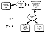
- Fig. 1 shows an exemplary environment 100 suitable for providing a scalable display system.
- Exemplary environment 100 includes a network computer 102 that handles requests for data, such as requests for video data from intermediate computer 104 over a computer network 106.
- network 106 is typically a remote IP (Internet Protocol) network connection, it can also include local connections depending on the particular system configuration.
- network 106 may include, for example, any one or a combination of a modem, a cable modem, a LAN (local area network), a WAN (wide area network), an intranet, the Internet, or any other suitable communication link.
- Network computer 102 and intermediate computer 104 may both be implemented as a variety of general purpose computing devices such as a server computer, a workstation computer, a desktop computer, a laptop computer, or other form of personal computer (PC), and may be configured in a manner similar to an exemplary computer implementation described below with reference to Fig. 7.
- Network computer 102 provides storage for electronic documents and information including various multi-media content that is accessible by intermediate computer 104 over computer network 106.
- Exemplary environment 100 also includes multiple client computers 108 that each drive a single display device, such as a computer screen or a projector for illuminating a display.
- client computers 108 that each drive a single display device, such as a computer screen or a projector for illuminating a display.
- the multiple smaller displays, each driven by a client 108 make up a large scalable display whose resolution is a function of the number of smaller displays combined to make up the larger display.
- Clients 108 may be implemented as any of a variety of client computing devices including, for example, a "thin client", a desktop computer, a server computer, a laptop computer, or other form of personal computer (PC), and may be configured in a manner similar to an exemplary computer implementation described below with reference to Fig. 7.
- client 108 would be similar to a PC, but may not include local storage capabilities.
- Thin clients also generally have an input device such as a mouse in addition to other communications capabilities.
- Clients 108 receive video data from intermediate computer 104 through a network 110.
- network 110 is typically a local connection such as a LAN, it can also include remote connections depending on the particular system configuration.
- network 110 may include, for example, any one or a combination of a modem, a cable modem, a LAN (local area network), a WAN (wide area network), an intranet, the Internet, or any other suitable communication link.
- intermediate computer 104 acts as a gateway device that presents itself as a single client to the network computer 102 while presenting itself as a server to the multiple clients 108.
- the exemplary environment 100 may be implemented in the context of a terminal services architecture, such as that provided by Windows 2000 Terminal Services from Microsoft® Corporation of Redmond, Washington.
- network computer 102 acts as a terminal server and intermediate computer 104 acts as a primary client to network computer 102.
- a remote terminal services environment using a remote protocol such as Microsoft's RDP (Remote Desktop Protocol), permits centralized deployment, maintenance and management of software, along with the re-use of existing hardware and thin-client terminal usage that reduces the overall costs of a system.
- a terminal services-type architecture significantly decreases the amount of time and money spent to upgrade, maintain and troubleshoot a system.
- keyboard and mouse data would travel to the network computer 102 from the intermediate computer 104, and only screen data (e.g., drawing instructions from video data) would be returned from the network computer 102 to the intermediate computer 104.
- the keyboard and mouse would be connected to intermediate computer 104, which acts as the client to network computer 102.
- cursor management would be managed at the intermediate computer 104 in such a way that only one of the smaller displays (driven by a client 108) has an active cursor.
- the intermediate computer 104 When the mouse is moved such that it crosses boundaries between smaller displays, the intermediate computer 104 would send a command to network computer 102 that the cursor position is lost and to reset its cursor to a null cursor. Another command would be sent to set its cursor position and shape to the appropriate value on a different smaller display driven by a different client 108.
- Exemplary environment 100 may also include a personal computer 112 or some other form of computer that is operatively coupled to intermediate computer 104 at various times, either directly or through a network (e.g., network 106, network 110), to provide configuration information to intermediate computer 104 regarding the physical layout and configuration of small displays that are combined to make up a large display.
- a network e.g., network 106, network 110
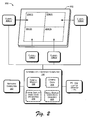
- Fig. 2 is a block diagram representation of an exemplary scalable display system 200.
- Scalable display 202 is a single high-resolution display comprising multiple physical display devices 204 that are each supported by a client device 108.
- Display devices 204 can be implemented in various ways including, for example, as computer monitors, CRT screens, or flat panel displays.
- the display devices 204 making up the scalable display 202 may be all the same, or they may vary in height and/or width to accommodate a particular design for scalable display 202.
- several flat panel displays of the same height but varying widths may be arranged as an arc of a circle to produce a very wide display 202.
- a set of projectors each driven by a client 108, may be configured to cover varying portions of an overhead dome (e.g., the inside of a planetarium).
- a scalable display system 200 can be implemented using multiple projectors 300, or other similar illumination devices, each illuminating a different section 302 of a display surface area 304.
- a scalable display 202 may comprise multiple projectors 300 along with the display surface area 304 being illuminated as generally illustrated in Fig. 3.
- display devices 204(1), 204(2), 204(3), and 204(4) are assembled into a grid that forms the larger scalable display 202.
- display devices 204(1), 204(2), 204(3), and 204(4) are illustrated as making up scalable display 202, it is noted that virtually any number of such devices may be combined in a similar fashion to scale the size and resolution of scalable display 202.
- additional displays 204 may be combined to extend scalable display 202 both vertically and horizontally.
- a scalable display 202 is not limited to a particular ratio of vertical length to horizontal length. That is, scalable display 202 may be configured to be longer horizontally than vertically, or longer vertically than horizontally, for example.
- any given scalable display 202 is increased by combining additional display devices 204, the resolution of the scalable display 202 increases accordingly. Therefore, the same number of image pixels is employed to implement a certain sized section of scalable display 202 regardless of how the overall size of scalable display 202 may increase or decrease. Thus, the number of image pixels per surface area of scalable display 202 remains constant.
- One beneficial result is that there is no loss in the quality of images displayed on scalable display 202 as the size of scalable display 202 is increased. In fact, the quality of any given image can improve as the size of scalable display 202 is increased, because there will be a greater number of image pixels to express a decreasing amount of the given image.
- Fig. 4 illustrates this advantage by showing an example of how a scalable display 202 may be scaled up in size.
- the example illustrates how scaling up the size of a scalable display 202 can improve the quality of the displayed image because of the greater number of image pixels employable to express the image.
- the smaller display devices 204 making up the scalable display 202 are illustrated as having a resolution of 1024 X 1024.
- the overall resolution is the combination of resolutions of the individual display devices 204.
- the overall resolution of the first display 202(1) is 2048 X 2048.
- additional display devices 204 are added in the vertical and horizontal directions.
- the second display 202(2) has been scaled up to include 16 display devices.
- the overall resolution of the scaled up second display 202(2) thus becomes 4096 X 4096. It is therefore apparent, that for a given image such as image 400, a greater number of image pixels are employed to display the image 400. This results in finer detail in the displayed image 400 and an increased image quality.
- each of the display devices 204(1), 204(2), 204(3), and 204(4) is supported or driven by a client computer 108.
- Each client 108 receives drawing data from intermediate computer 104 that is formatted for display based on the coordinates of a corresponding display device 204.
- client 1 108(1) receives drawing data from intermediate computer 104 that is formatted for display on display device 204(1).
- Intermediate computer 104 is a gateway device that presents itself as a single client to network computer 102, while presenting itself as a server to each of the clients 108.
- Intermediate computer 104 includes configuration module 206 and configuration data 208.
- Such components are discussed in the general context of computer/processor-executable instructions that are executable, for example, by a personal computer.
- Program modules generally include routines, programs, objects, components, data structures, etc., that perform particular tasks or implement particular abstract data types.
- Configuration module 206 is configured to receive configuration data 208 from a source such as PC 112.
- PC 112 is illustrated in Fig. 2 as one way in which configuration data 208 can be entered into intermediate computer 104.
- a user may implement configuration module 206 on intermediate computer 104 in order to enter configuration data 208 remotely through a Web browser running on PC 112.
- intermediate computer 104 may be configured with input/output devices (e.g., a keyboard and display - not shown) enabling a user to enter configuration data 208 locally.
- each client 108 provides configuration information to intermediate computer 104 regarding the size and position of a corresponding display device 204 the client 108 is driving.
- client 108(1) may provide configuration information to intermediate computer 104 regarding display device 204(1), and so on.
- Configuration data 208 includes information about which network computer 102 to connect to, the size of the overall scalable display 202, and the display devices 204 that make up scalable display 202.
- Information about the display devices 204 includes an identification (e.g., a name) for each display device 204, a physical location or position of each display device 204 within the scalable display 202, and a display resolution for each display device 204.
- configuration module 206 is also configured to communicate with network computer 102.
- Configuration module 206 sends requests to network computer 102 over network 106 asking for video data to be sent to intermediate computer 104 at particular display resolutions.
- the resolution requested depends on the overall resolution of the large scalable display 202.
- the overall resolution of the large scalable display 202 is the combination of the resolutions of the individual display devices 204.
- the resolution of the large scalable display 202 is 2048 X 1536.
- configuration module 206 determines the resolution of large scalable display 202 and makes requests for video data to network computer 102 accordingly.
- Network computer 102 honors requests for video data at whatever resolution is specified by configuration module 206 of intermediate computer 104. Because the video data received from network computer 102 is received in a format intended for display on a large display (i.e., according to the resolution requested from configuration module 206), it is illustrated in Figs. 2 and 3 on intermediate computer 104 as "large display video data" 210.
- intermediate computer 104 After intermediate computer 104 receives the large display video data 210 from network computer 102, configuration module 206 analyzes the data 210 and reconfigures it for display on appropriate display devices 204.
- the reconfigured large display video data 210 is illustrated in Figs. 2 and 3 on intermediate computer 104 as small display video data 212.
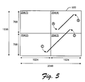
- Fig. 5 helps to illustrate how large display video data 210 may be reconfigured.
- Display 500 of Fig. 5 represents a large scalable display made up of 4 display devices 204(1), 204(2), 204(3), and 204(4).
- the large scalable display 500 shows a first drawing extending from point A to point B, and a second drawing that extends from point C to point D.
- a drawing instruction for the first drawing would include the coordinates (1280,896) to identify point A, and the coordinates (1792,1408) to identify point B.
- the coordinates for the drawing instruction must be converted from the large display 500 configuration to a small display configuration that is appropriate for display device 204(4).
- Configuration module 206 knows the resolution and the relative location of display device 204(4) from configuration data 208, and it uses this information to determine the appropriate coordinates for the first drawing to be displayed on display device 204(4).
- configuration module 206 converts large display video data 210 coordinates (1280,896) into small display video data 212 coordinates (256,128) to identify point A within display device 204(4). Likewise, configuration module 206 converts large display video data 210 coordinates (1792,1408) into small display video data 212 coordinates (768,640) to identify point B within display device 204(4). Configuration module 206 on intermediate computer 104 sends the small display video data 212 values to the appropriate display device 204(4) for display.
- the second drawing shown in Fig. 5 that extends from point C to point D provides another example of how configuration module 206 analyzes large display video data 210 and converts it for display as small display video data 212.
- the second drawing extending from point C to point D traverses 3 different display devices, 204(2), 204(3), and 204(4).
- Large display video data 210 from network computer 102 will express the second drawing with a single drawing command that identifies points C and D using coordinates appropriate for large scalable display 500.
- a new drawing command is created for each display device (i.e., 204(2), 204(3), and 204(4)) that describes the portion of the drawing to be displayed in each of the display devices.
- the portion of second drawing located in display device 204(2) may be defined in a drawing command with coordinates (896,128) to identify point C, and coordinates (1024,256) to identify the end of the portion of the second drawing at the edge of display device 204(2).
- Configuration module 206 on intermediate computer 104 analyzes all the large display video data 210 and converts it to small display video data 212 in this manner so that it can be sent to the appropriate display device 204 for display on the large scalable display 500.
- one of the client computers 104 may act as the intermediate computer 104.
- intermediate computer 104 and one of the client computers 104 may be one and the same computer device.
- the intermediate computer 104 operates in a manner similar to that discussed above. That is, it receives configuration information 208 regarding the large scalable display 202, the small displays 204, and network computer 102, and it requests and receives large display video data 210 based on the configuration information 208. It then proceeds to reconfigure the large display video data 210 into small display video data 212 and distributes the small display video data 212 to the appropriate client 108 for display.
- Example methods for providing a scalable display will now be described with primary reference to the flow diagram of Fig. 6.
- the methods apply to the exemplary embodiments discussed above with respect to Figs. 1 - 5.
- the elements of the described methods may be performed by any appropriate means including, for example, by hardware logic blocks on an ASIC or by the execution of processor-readable instructions defined on a processor-readable medium.
- a "processor-readable medium,” as used herein, can be any means that can contain, store, communicate, propagate, or transport instructions for use by or execution by a processor.
- a processor-readable medium can be, without limitation, an electronic, magnetic, optical, electromagnetic, infrared, or semiconductor system, apparatus, device, or propagation medium.
- processor-readable medium include, among others, an electrical connection (electronic) having one or more wires, a portable computer diskette (magnetic), a random access memory (RAM) (magnetic), a read-only memory (ROM) (magnetic), an erasable programmable-read-only memory (EPROM or Flash memory), an optical fiber (optical), a rewritable compact disc (CD-RW) (optical), and a portable compact disc read-only memory (CDROM) (optical).
- an electrical connection electronic having one or more wires
- a portable computer diskette magnetic
- RAM random access memory
- ROM read-only memory
- EPROM or Flash memory erasable programmable-read-only memory
- CD-RW rewritable compact disc
- CDROM portable compact disc read-only memory
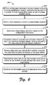
- Fig. 6 shows an exemplary method 600 for providing an integrated spatial view of scheduling information.
- spatial configuration information is received at an intermediate computer 104.
- the spatial configuration information includes a location, identification, and resolution for each of the small displays that make up a large scalable display.
- the configuration information can be entered in various ways, such as by a user via a PC 112 or on an individual basis from each client computer 108.
- the intermediate computer 104 waits for the client computers 108 to connect to it.
- the intermediate computer 104 acts as a server to each of the client computers 108.
- a large display resolution is determined based on the configuration information.
- Intermediate computer 104 determines the resolution of the large display 202 on the basis of the size and position of each of the multiple small displays 204 that make up large display 202.
- the intermediate computer 104 connects to network computer 102 over a computer network.
- the intermediate computer 104 advertises itself as a client having a large display, and it sends a request to the network computer 102 asking for the video data to be transmitted at the large display resolution.
- the network computer 102 honors the request, without knowing that the video data will be broken up and displayed on multiple small displays.
- video data intended for a large display is received at intermediate computer 104.
- the video data is formatted for display on the large display.
- the intermediate computer 104 reformats the video data so that it can be displayed on a number of small displays that make up the large display.
- the reformatted video data is distributed to at least some of the small displays. The distribution of reformatted data is made to appropriate clients 108 that each drive a small display.
- Fig. 7 illustrates an exemplary computing environment suitable for implementing a network computer 102, an intermediate computer 104, a client computer 108, and a PC 112, all as discussed above with reference to Figs. 1-6. Although one specific configuration is shown in Fig. 7, the network computer 102, intermediate computer 104, client computer 108, and PC 112 may be implemented in other computing configurations.
- the computing environment 700 includes a general-purpose computing system in the form of a computer 702.
- the components of computer 702 may include, but are not limited to, one or more processors or processing units 704, a system memory 706, and a system bus 708 that couples various system components including the processor 704 to the system memory 706.
- the system bus 708 represents one or more of any of several types of bus structures, including a memory bus or memory controller, a peripheral bus, an accelerated graphics port, and a processor or local bus using any of a variety of bus architectures.
- An example of a system bus 708 would be a Peripheral Component Interconnects (PCI) bus, also known as a Mezzanine bus.
- PCI Peripheral Component Interconnects
- Computer 702 includes a variety of computer-readable media. Such media can be any available media that is accessible by computer 702 and includes both volatile and non-volatile media, removable and non-removable media.
- the system memory 706 includes computer readable media in the form of volatile memory, such as random access memory (RAM) 710, and/or non-volatile memory, such as read only memory (ROM) 712.
- RAM 710 contains data and/or program modules that are immediately accessible to and/or presently operated on by the processing unit 704.
- Computer 702 may also include other removable/non-removable, volatile/non-volatile computer storage media.
- Fig. 7 illustrates a hard disk drive 716 for reading from and writing to a non-removable, non-volatile magnetic media (not shown), a magnetic disk drive 718 for reading from and writing to a removable, non-volatile magnetic disk 720 (e.g., a "floppy disk"), and an optical disk drive 722 for reading from and/or writing to a removable, non-volatile optical disk 724 such as a CD-ROM, DVD-ROM, or other optical media.
- a hard disk drive 716 for reading from and writing to a non-removable, non-volatile magnetic media (not shown)
- a magnetic disk drive 718 for reading from and writing to a removable, non-volatile magnetic disk 720 (e.g., a "floppy disk")
- an optical disk drive 722 for reading from and/or writing to a removable, non-volatile optical
- the hard disk drive 716, magnetic disk drive 718, and optical disk drive 722 are each connected to the system bus 708 by one or more data media interfaces 726.
- the hard disk drive 716, magnetic disk drive 718, and optical disk drive 722 may be connected to the system bus 708 by a SCSI interface (not shown).
- the disk drives and their associated computer-readable media provide non-volatile storage of computer readable instructions, data structures, program modules, and other data for computer 702.
- a hard disk 716 a removable magnetic disk 720, and a removable optical disk 724
- other types of computer readable media which can store data that is accessible by a computer, such as magnetic cassettes or other magnetic storage devices, flash memory cards, CD-ROM, digital versatile disks (DVD) or other optical storage, random access memories (RAM), read only memories (ROM), electrically erasable programmable read-only memory (EEPROM), and the like, can also be utilized to implement the exemplary computing system and environment.
- RAM random access memories
- ROM read only memories
- EEPROM electrically erasable programmable read-only memory
- Any number of program modules can be stored on the hard disk 716, magnetic disk 720, optical disk 724, ROM 712, and/or RAM 710, including by way of example, an operating system 726, one or more application programs 728, other program modules 730, and program data 732.
- an operating system 726 may include an embodiment of a caching scheme for user network access information.
- Computer 702 can include a variety of computer/processor readable media identified as communication media.
- Communication media embodies computer readable instructions, data structures, program modules, or other data in a modulated data signal such as a carrier wave or other transport mechanism and includes any information delivery media.
- modulated data signal means a signal that has one or more of its characteristics set or changed in such a manner as to encode information in the signal.
- communication media includes wired media such as a wired network or direct-wired connection, and wireless media such as acoustic, RF, infrared, and other wireless media. Combinations of any of the above are also included within the scope of computer readable media.
- a user can enter commands and information into computer system 702 via input devices such as a keyboard 734 and a pointing device 736 (e.g., a "mouse").
- Other input devices 738 may include a microphone, joystick, game pad, satellite dish, serial port, scanner, and/or the like.
- input/output interfaces 740 are coupled to the system bus 708, but may be connected by other interface and bus structures, such as a parallel port, game port, or a universal serial bus (USB).
- a monitor 742 or other type of display device may also be connected to the system bus 708 via an interface, such as a video adapter 744.
- other output peripheral devices may include components such as speakers (not shown) and a printer 746 which can be connected to computer 702 via the input/output interfaces 740.
- Computer 702 may operate in a networked environment using logical connections to one or more remote computers, such as a remote computing device 748.
- the remote computing device 748 can be a personal computer, portable computer, a server, a router, a network computer, a peer device or other common network node, and the like.
- the remote computing device 748 is illustrated as a portable computer that may include many or all of the elements and features described herein relative to computer system 702.
- Logical connections between computer 702 and the remote computer 748 are depicted as a local area network (LAN) 750 and a general wide area network (WAN) 752.
- LAN local area network
- WAN wide area network
- Such networking environments are commonplace in offices, enterprise-wide computer networks, intranets, and the Internet.
- the computer 702 is connected to a local network 750 via a network interface or adapter 754.
- the computer 702 includes a modem 756 or other means for establishing communications over the wide network 752.
- the modem 756, which can be internal or external to computer 702, can be connected to the system bus 708 via the input/output interfaces 740 or other appropriate mechanisms. It is to be appreciated that the illustrated network connections are exemplary and that other means of establishing communication link(s) between the computers 702 and 748 can be employed.
- remote application programs 758 reside on a memory device of remote computer 748.
- application programs and other executable program components such as the operating system, are illustrated herein as discrete blocks, although it is recognized that such programs and components reside at various times in different storage components of the computer system 702, and are executed by the data processor(s) of the computer.
Abstract
Description
- The present disclosure relates to display devices, and more particularly, to the use of multiple display devices in a single, high-resolution and scalable display.
- Current display systems such as projector systems and computer monitors have limitations when it comes to the size and quality of images they can display. The limitations result in a tradeoff between the size of a display and the quality of images presented on the display. More specifically, as the display size increases, the quality of the displayed image decreases. For example, the maximum resolution of a conference room projector system is currently 1024 X 768 image pixels. Regardless of the size of the display being projected from the projector, the resolution remains constant. Therefore, the same number of image pixels is used to display a projected image no matter what the size of the display. An increase in the display size (e.g., by backing up the projector) results in the stretching of each image pixel to cover a larger display surface, which degrades the quality of the image being displayed.
- The maximum resolution of display systems is ever-increasing. However, the relative cost increases associated with systems providing increased display resolution beyond the current level of 1024
X 768 is significant to the extent that such systems are prohibitively expensive for many consumers. - Accordingly, a need exists for a way to provide an inexpensive, high-resolution, and scalable display.
- A system and related methods are described for providing a high-resolution scalable display.
- In accordance with one implementation, an intermediate computer acts as a gateway computer between a network computer and multiple client computers. The intermediate computer receives configuration information regarding a large display wherein the large display is made up of multiple small displays. The intermediate computer determines a resolution of the large display based on the configuration information and sends a request over a computer network to the network computer for video data at the large screen resolution. The intermediate computer receives the video data configured for the large display and reconfigures the video data for display on the small displays that make up the large display.
- The same reference numerals are used throughout the drawings to reference like components and features.
- Fig. 1 illustrates an exemplary environment suitable for providing a scalable display system.
- Fig. 2 illustrates an exemplary block diagram representation of a scalable display system.
- Fig. 3 illustrates an embodiment of a scalable display comprising multiple projectors.
- Fig. 4 illustrates an example of how a scalable display may be scaled up in size.
- Fig. 5 illustrates how large display video data may be reconfigured as small display video data.
- Fig. 6 illustrates a block diagram of exemplary methods for providing a scalable display.
- Fig. 7 illustrates an exemplary computing environment suitable for implementing a network computer, an intermediate computer, a client, and a PC, such as those shown in the exemplary environment of Fig. 1.
-
- The following discussion is directed to systems and methods that provide for a large, high-resolution display that is scalable. The large display itself is made up of a number of smaller displays, each supporting a section of the large display. The resolution of the large display is the combined resolutions of the smaller displays according to the vertical and horizontal layout of the smaller displays. The system includes an intermediate computer that acts as a primary client to a network computer. The intermediate computer communicates with the network computer to request and receive video data at the large display resolution. The intermediate computer reconfigures video data from a format consistent with the large display coordinates to a format consistent with the coordinates of the individual smaller displays that make up the large display. The intermediate computer sends reconfigured video data to the smaller displays (through secondary clients) according to which portion of the large display each of the smaller displays supports.
- Advantages of the described systems and methods include the ability to grow a display size with increasing numbers of small displays while maintaining a high display resolution. Another advantage of the scalable display is its relatively low cost of creation through the use of commonly available smaller displays and existing terminal service systems. Another advantage of the scalable display system is the ease with which it can be maintained through the simple replacement of failed components with other readily available components. This is in contrast to a high-resolution system that may be rendered unavailable if a portion of the system fails.
- Fig. 1 shows an
exemplary environment 100 suitable for providing a scalable display system.Exemplary environment 100 includes anetwork computer 102 that handles requests for data, such as requests for video data fromintermediate computer 104 over acomputer network 106. Althoughnetwork 106 is typically a remote IP (Internet Protocol) network connection, it can also include local connections depending on the particular system configuration. Thus,network 106 may include, for example, any one or a combination of a modem, a cable modem, a LAN (local area network), a WAN (wide area network), an intranet, the Internet, or any other suitable communication link.Network computer 102 andintermediate computer 104 may both be implemented as a variety of general purpose computing devices such as a server computer, a workstation computer, a desktop computer, a laptop computer, or other form of personal computer (PC), and may be configured in a manner similar to an exemplary computer implementation described below with reference to Fig. 7.Network computer 102 provides storage for electronic documents and information including various multi-media content that is accessible byintermediate computer 104 overcomputer network 106. -
Exemplary environment 100 also includesmultiple client computers 108 that each drive a single display device, such as a computer screen or a projector for illuminating a display. As discussed below, the multiple smaller displays, each driven by aclient 108, make up a large scalable display whose resolution is a function of the number of smaller displays combined to make up the larger display.Clients 108 may be implemented as any of a variety of client computing devices including, for example, a "thin client", a desktop computer, a server computer, a laptop computer, or other form of personal computer (PC), and may be configured in a manner similar to an exemplary computer implementation described below with reference to Fig. 7. As a "thin client",client 108 would be similar to a PC, but may not include local storage capabilities. Thin clients also generally have an input device such as a mouse in addition to other communications capabilities. -
Clients 108 receive video data fromintermediate computer 104 through anetwork 110. Althoughnetwork 110 is typically a local connection such as a LAN, it can also include remote connections depending on the particular system configuration. Thus,network 110 may include, for example, any one or a combination of a modem, a cable modem, a LAN (local area network), a WAN (wide area network), an intranet, the Internet, or any other suitable communication link. To facilitate the transfer and display of video data fromnetwork computer 102 toclients 108,intermediate computer 104 acts as a gateway device that presents itself as a single client to thenetwork computer 102 while presenting itself as a server to themultiple clients 108. - In one embodiment, the
exemplary environment 100 may be implemented in the context of a terminal services architecture, such as that provided by Windows 2000 Terminal Services from Microsoft® Corporation of Redmond, Washington. In such a context,network computer 102 acts as a terminal server andintermediate computer 104 acts as a primary client tonetwork computer 102. A remote terminal services environment using a remote protocol, such as Microsoft's RDP (Remote Desktop Protocol), permits centralized deployment, maintenance and management of software, along with the re-use of existing hardware and thin-client terminal usage that reduces the overall costs of a system. A terminal services-type architecture significantly decreases the amount of time and money spent to upgrade, maintain and troubleshoot a system. In such a system, only keyboard and mouse data would travel to thenetwork computer 102 from theintermediate computer 104, and only screen data (e.g., drawing instructions from video data) would be returned from thenetwork computer 102 to theintermediate computer 104. The keyboard and mouse would be connected tointermediate computer 104, which acts as the client to networkcomputer 102. In general, cursor management would be managed at theintermediate computer 104 in such a way that only one of the smaller displays (driven by a client 108) has an active cursor. When the mouse is moved such that it crosses boundaries between smaller displays, theintermediate computer 104 would send a command to networkcomputer 102 that the cursor position is lost and to reset its cursor to a null cursor. Another command would be sent to set its cursor position and shape to the appropriate value on a different smaller display driven by adifferent client 108. -
Exemplary environment 100 may also include apersonal computer 112 or some other form of computer that is operatively coupled tointermediate computer 104 at various times, either directly or through a network (e.g.,network 106, network 110), to provide configuration information tointermediate computer 104 regarding the physical layout and configuration of small displays that are combined to make up a large display. - Fig. 2 is a block diagram representation of an exemplary
scalable display system 200.Scalable display 202 is a single high-resolution display comprising multiplephysical display devices 204 that are each supported by aclient device 108.Display devices 204 can be implemented in various ways including, for example, as computer monitors, CRT screens, or flat panel displays. For any givenscalable display 202, thedisplay devices 204 making up thescalable display 202 may be all the same, or they may vary in height and/or width to accommodate a particular design forscalable display 202. For example, several flat panel displays of the same height but varying widths may be arranged as an arc of a circle to produce a verywide display 202. In another application, a set of projectors, each driven by aclient 108, may be configured to cover varying portions of an overhead dome (e.g., the inside of a planetarium). Accordingly, as illustrated in Fig. 3, ascalable display system 200 can be implemented usingmultiple projectors 300, or other similar illumination devices, each illuminating adifferent section 302 of adisplay surface area 304. Thus, ascalable display 202 may comprisemultiple projectors 300 along with thedisplay surface area 304 being illuminated as generally illustrated in Fig. 3. Although the following discussion makes primary reference to the exemplaryscalable display system 200 of Fig. 2, it generally applies in an equivalent manner to the exemplaryscalable display system 200 of Fig. 3. - Referring to Fig. 2, display devices 204(1), 204(2), 204(3), and 204(4) are assembled into a grid that forms the larger
scalable display 202. Although only 4 display devices 204(1), 204(2), 204(3), and 204(4) are illustrated as making upscalable display 202, it is noted that virtually any number of such devices may be combined in a similar fashion to scale the size and resolution ofscalable display 202. Thus,additional displays 204 may be combined to extendscalable display 202 both vertically and horizontally. Furthermore, as the number ofdisplays 204 increases, ascalable display 202 is not limited to a particular ratio of vertical length to horizontal length. That is,scalable display 202 may be configured to be longer horizontally than vertically, or longer vertically than horizontally, for example. - In addition, as the size of any given
scalable display 202 is increased by combiningadditional display devices 204, the resolution of thescalable display 202 increases accordingly. Therefore, the same number of image pixels is employed to implement a certain sized section ofscalable display 202 regardless of how the overall size ofscalable display 202 may increase or decrease. Thus, the number of image pixels per surface area ofscalable display 202 remains constant. One beneficial result is that there is no loss in the quality of images displayed onscalable display 202 as the size ofscalable display 202 is increased. In fact, the quality of any given image can improve as the size ofscalable display 202 is increased, because there will be a greater number of image pixels to express a decreasing amount of the given image. - Fig. 4 illustrates this advantage by showing an example of how a
scalable display 202 may be scaled up in size. For a given image, assuming sufficient image data is available, the example illustrates how scaling up the size of ascalable display 202 can improve the quality of the displayed image because of the greater number of image pixels employable to express the image. For ease of discussion, thesmaller display devices 204 making up thescalable display 202 are illustrated as having a resolution of 1024X 1024. In the first display 202(1) of Fig. 4, the overall resolution is the combination of resolutions of theindividual display devices 204. Thus, the overall resolution of the first display 202(1) is 2048X 2048. To scale up the first display 202(1),additional display devices 204 are added in the vertical and horizontal directions. In the Fig. 4 example, the second display 202(2) has been scaled up to include 16 display devices. The overall resolution of the scaled up second display 202(2) thus becomes 4096 X 4096. It is therefore apparent, that for a given image such asimage 400, a greater number of image pixels are employed to display theimage 400. This results in finer detail in the displayedimage 400 and an increased image quality. - Referring again to Fig. 2, each of the display devices 204(1), 204(2), 204(3), and 204(4) is supported or driven by a
client computer 108. Eachclient 108 receives drawing data fromintermediate computer 104 that is formatted for display based on the coordinates of acorresponding display device 204. Thus, client1 108(1) receives drawing data fromintermediate computer 104 that is formatted for display on display device 204(1). -
Intermediate computer 104 is a gateway device that presents itself as a single client to networkcomputer 102, while presenting itself as a server to each of theclients 108.Intermediate computer 104 includesconfiguration module 206 andconfiguration data 208. Such components are discussed in the general context of computer/processor-executable instructions that are executable, for example, by a personal computer. Program modules generally include routines, programs, objects, components, data structures, etc., that perform particular tasks or implement particular abstract data types.Configuration module 206 is configured to receiveconfiguration data 208 from a source such asPC 112.PC 112 is illustrated in Fig. 2 as one way in whichconfiguration data 208 can be entered intointermediate computer 104. Thus, a user may implementconfiguration module 206 onintermediate computer 104 in order to enterconfiguration data 208 remotely through a Web browser running onPC 112. This is, however, only one of various ways a user may enterconfiguration data 208 intointermediate computer 104. For example,intermediate computer 104 may be configured with input/output devices (e.g., a keyboard and display - not shown) enabling a user to enterconfiguration data 208 locally. In another embodiment, eachclient 108 provides configuration information tointermediate computer 104 regarding the size and position of acorresponding display device 204 theclient 108 is driving. For example, client 108(1) may provide configuration information tointermediate computer 104 regarding display device 204(1), and so on. -
Configuration data 208 includes information about whichnetwork computer 102 to connect to, the size of the overallscalable display 202, and thedisplay devices 204 that make upscalable display 202. Information about thedisplay devices 204 includes an identification (e.g., a name) for eachdisplay device 204, a physical location or position of eachdisplay device 204 within thescalable display 202, and a display resolution for eachdisplay device 204. - In addition to receiving
configuration data 208,configuration module 206 is also configured to communicate withnetwork computer 102.Configuration module 206 sends requests to networkcomputer 102 overnetwork 106 asking for video data to be sent tointermediate computer 104 at particular display resolutions. The resolution requested depends on the overall resolution of the largescalable display 202. As discussed above, the overall resolution of the largescalable display 202 is the combination of the resolutions of theindividual display devices 204. Thus, if the resolution ofindividual display devices 204 in Fig. 2 is 1024X 768, then the resolution of the largescalable display 202 is 2048X 1536. Based onconfiguration data 208,configuration module 206 determines the resolution of largescalable display 202 and makes requests for video data to networkcomputer 102 accordingly.Network computer 102 honors requests for video data at whatever resolution is specified byconfiguration module 206 ofintermediate computer 104. Because the video data received fromnetwork computer 102 is received in a format intended for display on a large display (i.e., according to the resolution requested from configuration module 206), it is illustrated in Figs. 2 and 3 onintermediate computer 104 as "large display video data" 210. - After
intermediate computer 104 receives the largedisplay video data 210 fromnetwork computer 102,configuration module 206 analyzes thedata 210 and reconfigures it for display onappropriate display devices 204. The reconfigured largedisplay video data 210 is illustrated in Figs. 2 and 3 onintermediate computer 104 as smalldisplay video data 212. Fig. 5 helps to illustrate how largedisplay video data 210 may be reconfigured. Display 500 of Fig. 5 represents a large scalable display made up of 4 display devices 204(1), 204(2), 204(3), and 204(4). The largescalable display 500 shows a first drawing extending from point A to point B, and a second drawing that extends from point C to point D. According to the largedisplay video data 210, a drawing instruction for the first drawing would include the coordinates (1280,896) to identify point A, and the coordinates (1792,1408) to identify point B. However, because the first drawing is located on display device 204(4) of the largescalable display 500, the coordinates for the drawing instruction must be converted from thelarge display 500 configuration to a small display configuration that is appropriate for display device 204(4).Configuration module 206 knows the resolution and the relative location of display device 204(4) fromconfiguration data 208, and it uses this information to determine the appropriate coordinates for the first drawing to be displayed on display device 204(4). Thus,configuration module 206 converts largedisplay video data 210 coordinates (1280,896) into smalldisplay video data 212 coordinates (256,128) to identify point A within display device 204(4). Likewise,configuration module 206 converts largedisplay video data 210 coordinates (1792,1408) into smalldisplay video data 212 coordinates (768,640) to identify point B within display device 204(4).Configuration module 206 onintermediate computer 104 sends the smalldisplay video data 212 values to the appropriate display device 204(4) for display. - The second drawing shown in Fig. 5 that extends from point C to point D provides another example of how
configuration module 206 analyzes largedisplay video data 210 and converts it for display as smalldisplay video data 212. The second drawing extending from point C to point D traverses 3 different display devices, 204(2), 204(3), and 204(4). Largedisplay video data 210 fromnetwork computer 102 will express the second drawing with a single drawing command that identifies points C and D using coordinates appropriate for largescalable display 500. However, because the second drawing spans 3 different display devices, a new drawing command is created for each display device (i.e., 204(2), 204(3), and 204(4)) that describes the portion of the drawing to be displayed in each of the display devices. As an example, the portion of second drawing located in display device 204(2) may be defined in a drawing command with coordinates (896,128) to identify point C, and coordinates (1024,256) to identify the end of the portion of the second drawing at the edge of display device 204(2).Configuration module 206 onintermediate computer 104 analyzes all the largedisplay video data 210 and converts it to smalldisplay video data 212 in this manner so that it can be sent to theappropriate display device 204 for display on the largescalable display 500. - In another embodiment, one of the
client computers 104 may act as theintermediate computer 104. Thus,intermediate computer 104 and one of theclient computers 104 may be one and the same computer device. In such a configuration, theintermediate computer 104 operates in a manner similar to that discussed above. That is, it receivesconfiguration information 208 regarding the largescalable display 202, thesmall displays 204, andnetwork computer 102, and it requests and receives largedisplay video data 210 based on theconfiguration information 208. It then proceeds to reconfigure the largedisplay video data 210 into smalldisplay video data 212 and distributes the smalldisplay video data 212 to theappropriate client 108 for display. - Example methods for providing a scalable display will now be described with primary reference to the flow diagram of Fig. 6. The methods apply to the exemplary embodiments discussed above with respect to Figs. 1 - 5. The elements of the described methods may be performed by any appropriate means including, for example, by hardware logic blocks on an ASIC or by the execution of processor-readable instructions defined on a processor-readable medium.
- A "processor-readable medium," as used herein, can be any means that can contain, store, communicate, propagate, or transport instructions for use by or execution by a processor. A processor-readable medium can be, without limitation, an electronic, magnetic, optical, electromagnetic, infrared, or semiconductor system, apparatus, device, or propagation medium. More specific examples of a processor-readable medium include, among others, an electrical connection (electronic) having one or more wires, a portable computer diskette (magnetic), a random access memory (RAM) (magnetic), a read-only memory (ROM) (magnetic), an erasable programmable-read-only memory (EPROM or Flash memory), an optical fiber (optical), a rewritable compact disc (CD-RW) (optical), and a portable compact disc read-only memory (CDROM) (optical).
- Fig. 6 shows an
exemplary method 600 for providing an integrated spatial view of scheduling information. Atblock 602, spatial configuration information is received at anintermediate computer 104. The spatial configuration information includes a location, identification, and resolution for each of the small displays that make up a large scalable display. The configuration information can be entered in various ways, such as by a user via aPC 112 or on an individual basis from eachclient computer 108. - At
block 604, theintermediate computer 104 waits for theclient computers 108 to connect to it. In this respect, theintermediate computer 104 acts as a server to each of theclient computers 108. Atblock 606, a large display resolution is determined based on the configuration information.Intermediate computer 104 determines the resolution of thelarge display 202 on the basis of the size and position of each of the multiplesmall displays 204 that make uplarge display 202. - At
block 608, theintermediate computer 104 connects to networkcomputer 102 over a computer network. Theintermediate computer 104 advertises itself as a client having a large display, and it sends a request to thenetwork computer 102 asking for the video data to be transmitted at the large display resolution. Thenetwork computer 102 honors the request, without knowing that the video data will be broken up and displayed on multiple small displays. - At
block 610, video data intended for a large display is received atintermediate computer 104. The video data is formatted for display on the large display. Atblock 612, theintermediate computer 104 reformats the video data so that it can be displayed on a number of small displays that make up the large display. Atblock 614, the reformatted video data is distributed to at least some of the small displays. The distribution of reformatted data is made toappropriate clients 108 that each drive a small display. - While one or more methods have been disclosed by means of flow diagrams and text associated with the blocks of the flow diagrams, it is to be understood that the blocks do not necessarily have to be performed in the order in which they were presented, and that an alternative order(s) may result in similar advantages. Furthermore, the methods are not exclusive and can be performed alone or in combination with one another.
- Fig. 7 illustrates an exemplary computing environment suitable for implementing a
network computer 102, anintermediate computer 104, aclient computer 108, and aPC 112, all as discussed above with reference to Figs. 1-6. Although one specific configuration is shown in Fig. 7, thenetwork computer 102,intermediate computer 104,client computer 108, andPC 112 may be implemented in other computing configurations. - The
computing environment 700 includes a general-purpose computing system in the form of acomputer 702. The components ofcomputer 702 may include, but are not limited to, one or more processors orprocessing units 704, asystem memory 706, and asystem bus 708 that couples various system components including theprocessor 704 to thesystem memory 706. - The
system bus 708 represents one or more of any of several types of bus structures, including a memory bus or memory controller, a peripheral bus, an accelerated graphics port, and a processor or local bus using any of a variety of bus architectures. An example of asystem bus 708 would be a Peripheral Component Interconnects (PCI) bus, also known as a Mezzanine bus. -
Computer 702 includes a variety of computer-readable media. Such media can be any available media that is accessible bycomputer 702 and includes both volatile and non-volatile media, removable and non-removable media. Thesystem memory 706 includes computer readable media in the form of volatile memory, such as random access memory (RAM) 710, and/or non-volatile memory, such as read only memory (ROM) 712. A basic input/output system (BIOS) 714, containing the basic routines that help to transfer information between elements withincomputer 702, such as during start-up, is stored inROM 712. RAM 710 contains data and/or program modules that are immediately accessible to and/or presently operated on by theprocessing unit 704. -
Computer 702 may also include other removable/non-removable, volatile/non-volatile computer storage media. By way of example, Fig. 7 illustrates ahard disk drive 716 for reading from and writing to a non-removable, non-volatile magnetic media (not shown), amagnetic disk drive 718 for reading from and writing to a removable, non-volatile magnetic disk 720 (e.g., a "floppy disk"), and an optical disk drive 722 for reading from and/or writing to a removable, non-volatileoptical disk 724 such as a CD-ROM, DVD-ROM, or other optical media. Thehard disk drive 716,magnetic disk drive 718, and optical disk drive 722 are each connected to thesystem bus 708 by one or more data media interfaces 726. Alternatively, thehard disk drive 716,magnetic disk drive 718, and optical disk drive 722 may be connected to thesystem bus 708 by a SCSI interface (not shown). - The disk drives and their associated computer-readable media provide non-volatile storage of computer readable instructions, data structures, program modules, and other data for
computer 702. Although the example illustrates ahard disk 716, a removablemagnetic disk 720, and a removableoptical disk 724, it is to be appreciated that other types of computer readable media which can store data that is accessible by a computer, such as magnetic cassettes or other magnetic storage devices, flash memory cards, CD-ROM, digital versatile disks (DVD) or other optical storage, random access memories (RAM), read only memories (ROM), electrically erasable programmable read-only memory (EEPROM), and the like, can also be utilized to implement the exemplary computing system and environment. - Any number of program modules can be stored on the
hard disk 716,magnetic disk 720,optical disk 724,ROM 712, and/or RAM 710, including by way of example, anoperating system 726, one ormore application programs 728,other program modules 730, andprogram data 732. Each ofsuch operating system 726, one ormore application programs 728,other program modules 730, and program data 732 (or some combination thereof) may include an embodiment of a caching scheme for user network access information. -
Computer 702 can include a variety of computer/processor readable media identified as communication media. Communication media embodies computer readable instructions, data structures, program modules, or other data in a modulated data signal such as a carrier wave or other transport mechanism and includes any information delivery media. The term "modulated data signal" means a signal that has one or more of its characteristics set or changed in such a manner as to encode information in the signal. By way of example, and not limitation, communication media includes wired media such as a wired network or direct-wired connection, and wireless media such as acoustic, RF, infrared, and other wireless media. Combinations of any of the above are also included within the scope of computer readable media. - A user can enter commands and information into
computer system 702 via input devices such as akeyboard 734 and a pointing device 736 (e.g., a "mouse"). Other input devices 738 (not shown specifically) may include a microphone, joystick, game pad, satellite dish, serial port, scanner, and/or the like. These and other input devices are connected to theprocessing unit 704 via input/output interfaces 740 that are coupled to thesystem bus 708, but may be connected by other interface and bus structures, such as a parallel port, game port, or a universal serial bus (USB). - A
monitor 742 or other type of display device may also be connected to thesystem bus 708 via an interface, such as avideo adapter 744. In addition to themonitor 742, other output peripheral devices may include components such as speakers (not shown) and aprinter 746 which can be connected tocomputer 702 via the input/output interfaces 740. -
Computer 702 may operate in a networked environment using logical connections to one or more remote computers, such as aremote computing device 748. By way of example, theremote computing device 748 can be a personal computer, portable computer, a server, a router, a network computer, a peer device or other common network node, and the like. Theremote computing device 748 is illustrated as a portable computer that may include many or all of the elements and features described herein relative tocomputer system 702. - Logical connections between
computer 702 and theremote computer 748 are depicted as a local area network (LAN) 750 and a general wide area network (WAN) 752. Such networking environments are commonplace in offices, enterprise-wide computer networks, intranets, and the Internet. When implemented in a LAN networking environment, thecomputer 702 is connected to alocal network 750 via a network interface oradapter 754. When implemented in a WAN networking environment, thecomputer 702 includes amodem 756 or other means for establishing communications over thewide network 752. Themodem 756, which can be internal or external tocomputer 702, can be connected to thesystem bus 708 via the input/output interfaces 740 or other appropriate mechanisms. It is to be appreciated that the illustrated network connections are exemplary and that other means of establishing communication link(s) between thecomputers - In a networked environment, such as that illustrated with
computing environment 700, program modules depicted relative to thecomputer 702, or portions thereof, may be stored in a remote memory storage device. By way of example,remote application programs 758 reside on a memory device ofremote computer 748. For purposes of illustration, application programs and other executable program components, such as the operating system, are illustrated herein as discrete blocks, although it is recognized that such programs and components reside at various times in different storage components of thecomputer system 702, and are executed by the data processor(s) of the computer. - Although the invention has been described in language specific to structural features and/or methodological acts, it is to be understood that the invention defined in the appended claims is not necessarily limited to the specific features or acts described. Rather, the specific features and acts are disclosed as exemplary forms of implementing the claimed invention.
Claims (21)
- A method comprising:receiving video data over a network from a network computer, the video data formatted for display on a large display;reformatting the video data on an intermediate computer for display on a number of small displays that make up the large display; anddistributing reformatted video data from the intermediate computer to at least some of the small displays.
- A method as recited in claim 1, wherein the distributing comprises distributing the reformatted video data to clients, each client configured to drive a small display.
- A method as recited in claim 1, further comprising:receiving configuration information at the intermediate computer that includes an identification, a location, and a screen resolution for each of the small displays;determining a large display resolution based on the configuration information; andsending a request to the network computer from the intermediate computer to transfer the video data from the network computer to the intermediate computer at the large display resolution.
- A method as recited in claim 1, wherein the reformatting comprises converting coordinates of drawing commands from large display coordinates into small display coordinates.
- A method as recited in claim 1, wherein the reformatting comprises creating multiple drawing commands from a single drawing command, wherein the single drawing command would otherwise control a drawing that spans two or more of the small displays.
- A processor-readable medium comprising processor-executable instructions configured for:receiving configuration information at an intermediate computer regarding an assembly of small displays that forms a large display;receiving video data over a computer network at the intermediate computer, the video data configured for display on the large display;reconfiguring the video data for display on the small displays in accordance with the configuration information; andsending reconfigured video data from the intermediate computer to the small displays.
- A processor-readable medium as recited in claim 6, comprising further processor-executable instructions configured for:determining a large display resolution from the configuration information; andrequesting from a network computer, the video data at the large display resolution.
- A processor-readable medium as recited in claim 7:wherein the configuration information includes an identification for each small display, a location of each small display within the large display, and a small display resolution for each small display; andwherein the determining a large display resolution comprises summing the small display resolutions according to the location of each small display within the large display.
- A processor-readable medium as recited in claim 6, wherein the reconfiguring the video data comprises performing an operation selected from the group comprising:altering coordinates of a drawing command to correspond to a small display; andcreating multiple new drawing commands from a single drawing command, each new drawing command corresponding to a small display.
- A processor-readable medium as recited in claim 6, wherein the sending comprises determining which small displays to send reconfigured video data to based on which portion of the large display each of the small displays supports.
- A computer comprising the processor-readable medium recited in claim 6.
- A system comprising:a number of small displays assembled as a large display whose size and resolution are scalable by altering the number of small displays; anda gateway computer configured to reformat large display video data appropriate for display on the large display into small display video data appropriate for display on the small displays depending on how the small displays are assembled.
- A system as recited in claim 12, further comprising a number of clients each configured to drive a distinct one of the small displays with small display video data received from the gateway computer.
- A system as recited in claim 12, further comprising a configuration module configured as a part of the gateway computer to receive identification information, location information, and resolution information about each of the small displays, and to calculate the resolution of the large display based on the information.
- A system as recited in claim 12, further comprising a network computer, the gateway computer being further configured to request the large display video data from the network computer at the resolution of the large display.
- A system as recited in claim 12, wherein the small displays are selected from the group comprising:flat panel displays;computer monitors; andprojectors that illuminate separate portions of a display surface.
- A system as recited in claim 12, wherein the gateway computer and one of the clients are one and the same device.
- A computer comprising:a configuration module configured to receive over a computer network, video data formatted for a large display, and to reformat the video data for one or more small displays that make up the large display.
- A computer as recited in claim 18, further comprising configuration data indicating an identification, a location within the large display, and a resolution for each of the small displays.
- A computer as recited in claim 18, further comprising large display video data received from a network computer, the large display video data formatted for display on the large display.
- A computer as recited in claim 20, further comprising small display video data for sending to one or more of multiple clients, each client configured to drive a small display, the small display video data reformatted from the large display video data by the configuration module according to the configuration data.
Applications Claiming Priority (2)
| Application Number | Priority Date | Filing Date | Title |
|---|---|---|---|
| US728273 | 2003-12-04 | ||
| US10/728,273 US7737910B2 (en) | 2003-12-04 | 2003-12-04 | Scalable display |
Publications (2)
| Publication Number | Publication Date |
|---|---|
| EP1538524A2 true EP1538524A2 (en) | 2005-06-08 |
| EP1538524A3 EP1538524A3 (en) | 2007-12-12 |
Family
ID=34465779
Family Applications (1)
| Application Number | Title | Priority Date | Filing Date |
|---|---|---|---|
| EP04026924A Ceased EP1538524A3 (en) | 2003-12-04 | 2004-11-12 | Scalable display |
Country Status (5)
| Country | Link |
|---|---|
| US (1) | US7737910B2 (en) |
| EP (1) | EP1538524A3 (en) |
| JP (1) | JP4762532B2 (en) |
| KR (1) | KR101122968B1 (en) |
| CN (1) | CN100430885C (en) |
Cited By (3)
| Publication number | Priority date | Publication date | Assignee | Title |
|---|---|---|---|---|
| GB2447768A (en) * | 2007-03-21 | 2008-09-24 | Legend Holdings Ltd | Network projection system |
| EP2109287A1 (en) * | 2008-04-10 | 2009-10-14 | Mike Chih-Kang Liang | Multiple client control system |
| WO2023179154A1 (en) * | 2022-03-24 | 2023-09-28 | 华为云计算技术有限公司 | Method, apparatus and system for updating cursor |
Families Citing this family (23)
| Publication number | Priority date | Publication date | Assignee | Title |
|---|---|---|---|---|
| US7533099B2 (en) * | 2004-12-02 | 2009-05-12 | Microsoft Corporation | Componentized remote user interface |
| US7460134B2 (en) * | 2004-03-02 | 2008-12-02 | Microsoft Corporation | System and method for moving computer displayable content into a preferred user interactive focus area |
| CA2538812A1 (en) * | 2005-03-08 | 2006-09-08 | William Wright | System and method for large scale information analysis using data visualization techniques |
| JP4591247B2 (en) * | 2005-07-15 | 2010-12-01 | 株式会社日立製作所 | Information display method |
| US7489323B2 (en) * | 2006-01-10 | 2009-02-10 | Delta Electronics, Inc. | Display apparatus adapted for a display wall, image adjustment method therefor and display wall therewith |
| US7439937B2 (en) * | 2006-04-14 | 2008-10-21 | Microsoft Corporation | Appropriately rendering terminal server graphical data at multiple client side monitors |
| WO2008041605A1 (en) * | 2006-09-29 | 2008-04-10 | Brother Kogyo Kabushiki Kaisha | Projection apparatus, recording medium with program recoded therein, projection method and projection system |
| JP2008090563A (en) * | 2006-09-29 | 2008-04-17 | Brother Ind Ltd | Projection device |
| US20080136819A1 (en) * | 2006-12-11 | 2008-06-12 | Michael Shivas | Apparatus and method for screen scaling displays on communication devices |
| US20090267867A1 (en) * | 2008-04-28 | 2009-10-29 | Honeywell International Inc. | Display extension of portable devices |
| JP5077272B2 (en) * | 2009-03-12 | 2012-11-21 | カシオ計算機株式会社 | Client device, server-based computing system, and client control program |
| US20120154256A1 (en) * | 2010-08-06 | 2012-06-21 | Brett Loring Grover | Visual Display System |
| CN102270421B (en) * | 2011-01-17 | 2012-09-19 | 深圳市保千里电子有限公司 | System for joining display units and realizing method thereof |
| CN102109972B (en) * | 2011-02-14 | 2012-09-12 | 深圳雅图数字视频技术有限公司 | Projector television wall display method and system |
| JP5351198B2 (en) | 2011-03-23 | 2013-11-27 | シャープ株式会社 | Multi display system |
| CN102609232A (en) * | 2012-03-09 | 2012-07-25 | 刘尚俊 | Splicing display wall, display method, system and intelligent display device |
| JP2013020629A (en) * | 2012-08-23 | 2013-01-31 | Casio Comput Co Ltd | Terminal device and program |
| CN103399722B (en) * | 2013-08-27 | 2016-08-17 | 王艳 | A kind of Digital Clustering transmission and control system |
| CN103399723B (en) * | 2013-08-27 | 2016-08-10 | 王艳 | Large-screen display control system and method |
| JP6544073B2 (en) * | 2015-06-22 | 2019-07-17 | セイコーエプソン株式会社 | Image display system and image display method |
| CN105824593B (en) * | 2016-03-09 | 2018-11-13 | 京东方科技集团股份有限公司 | Splice screen display system and splicing display method |
| KR102385270B1 (en) | 2018-07-02 | 2022-04-12 | 삼성전자주식회사 | Electronic apparatus and method for controlling thereof |
| US10951877B2 (en) * | 2019-07-15 | 2021-03-16 | Msg Entertainment Group, Llc | Providing a contiguous virtual space for a plurality of display devices |
Citations (2)
| Publication number | Priority date | Publication date | Assignee | Title |
|---|---|---|---|---|
| US6348933B1 (en) * | 1998-07-20 | 2002-02-19 | Hewlett-Packard Company | Single logical screen display using multiple remote computer systems |
| US6611241B1 (en) * | 1997-12-02 | 2003-08-26 | Sarnoff Corporation | Modular display system |
Family Cites Families (13)
| Publication number | Priority date | Publication date | Assignee | Title |
|---|---|---|---|---|
| US4562450A (en) * | 1983-03-07 | 1985-12-31 | International Business Machines Corporation | Data management for plasma display |
| EP0568526B1 (en) * | 1990-02-16 | 1998-01-28 | Nadimelia (Overseas) Limited | Display system |
| US6333750B1 (en) * | 1997-03-12 | 2001-12-25 | Cybex Computer Products Corporation | Multi-sourced video distribution hub |
| JP2004500731A (en) | 1998-06-18 | 2004-01-08 | ソニー エレクトロニクス インク | Method and apparatus for splitting, scaling and displaying video and / or graphic images across multiple display devices |
| JP2000324437A (en) * | 1999-05-13 | 2000-11-24 | Fuurie Kk | Video database system |
| JP3756035B2 (en) * | 2000-03-14 | 2006-03-15 | 株式会社日立製作所 | Image / video display unit, image / video display apparatus and image / video display method using the same |
| US6850235B2 (en) * | 2000-12-27 | 2005-02-01 | Fly Over Technologies Inc. | Efficient image parcel texture rendering with T-junction crack elimination |
| MXPA03012070A (en) * | 2001-06-29 | 2005-08-16 | Novus Comm Technologies | Dynamic device and method for billboard advertising. |
| JP3693246B2 (en) * | 2001-12-28 | 2005-09-07 | ソニー株式会社 | Display device, control method, program, recording medium, and display system |
| CN100590586C (en) * | 2002-05-01 | 2010-02-17 | 联想(新加坡)私人有限公司 | Computer and display device setting method |
| US6999045B2 (en) * | 2002-07-10 | 2006-02-14 | Eastman Kodak Company | Electronic system for tiled displays |
| JP3941785B2 (en) * | 2003-03-13 | 2007-07-04 | セイコーエプソン株式会社 | Film forming method and color filter substrate manufacturing method |
| US8046701B2 (en) * | 2003-08-07 | 2011-10-25 | Fuji Xerox Co., Ltd. | Peer to peer gesture based modular presentation system |
-
2003
- 2003-12-04 US US10/728,273 patent/US7737910B2/en active Active
-
2004
- 2004-11-12 EP EP04026924A patent/EP1538524A3/en not_active Ceased
- 2004-12-03 JP JP2004351580A patent/JP4762532B2/en active Active
- 2004-12-03 KR KR1020040101036A patent/KR101122968B1/en active IP Right Grant
- 2004-12-03 CN CNB2004101001756A patent/CN100430885C/en not_active Expired - Fee Related
Patent Citations (2)
| Publication number | Priority date | Publication date | Assignee | Title |
|---|---|---|---|---|
| US6611241B1 (en) * | 1997-12-02 | 2003-08-26 | Sarnoff Corporation | Modular display system |
| US6348933B1 (en) * | 1998-07-20 | 2002-02-19 | Hewlett-Packard Company | Single logical screen display using multiple remote computer systems |
Cited By (4)
| Publication number | Priority date | Publication date | Assignee | Title |
|---|---|---|---|---|
| GB2447768A (en) * | 2007-03-21 | 2008-09-24 | Legend Holdings Ltd | Network projection system |
| GB2447768B (en) * | 2007-03-21 | 2009-09-30 | Legend Holdings Ltd | Virtual network projection system supporting multiple projection sources and method thereof |
| EP2109287A1 (en) * | 2008-04-10 | 2009-10-14 | Mike Chih-Kang Liang | Multiple client control system |
| WO2023179154A1 (en) * | 2022-03-24 | 2023-09-28 | 华为云计算技术有限公司 | Method, apparatus and system for updating cursor |
Also Published As
| Publication number | Publication date |
|---|---|
| JP4762532B2 (en) | 2011-08-31 |
| US20050125488A1 (en) | 2005-06-09 |
| JP2005165335A (en) | 2005-06-23 |
| KR101122968B1 (en) | 2012-03-15 |
| EP1538524A3 (en) | 2007-12-12 |
| CN1637844A (en) | 2005-07-13 |
| US7737910B2 (en) | 2010-06-15 |
| KR20050054463A (en) | 2005-06-10 |
| CN100430885C (en) | 2008-11-05 |
Similar Documents
| Publication | Publication Date | Title |
|---|---|---|
| US7737910B2 (en) | Scalable display | |
| US10367915B2 (en) | Optimized image delivery over limited bandwidth communication channels | |
| US8237740B2 (en) | Method and system for receiving a local vector object and viewing a vector image | |
| US7644131B2 (en) | Optimized image delivery over limited bandwidth communication channels | |
| US6710753B2 (en) | Multi-screen session mobility between terminal groups | |
| KR101201026B1 (en) | System and method for providing a composite display | |
| US5754242A (en) | Data formatting system for processing multiple independent input data streams for high resolution screen displays | |
| US7281213B2 (en) | System and method for network transmission of graphical data through a distributed application | |
| US20110047476A1 (en) | Image-based remote access system | |
| CN108388460A (en) | Long-range real-time rendering platform construction method based on graphics cluster | |
| MX2010011964A (en) | Virtual desktop view scrolling. | |
| CN101933041A (en) | Graphics remoting architecture | |
| CN102362477A (en) | Method for the remote sharing of computer office(s) | |
| US20050166214A1 (en) | System and method for managing graphics applications | |
| TW554283B (en) | Data processing system for generating graphics data and method of communicating graphics data | |
| US20050289176A1 (en) | Application sharing smoothness | |
| US6215486B1 (en) | Event handling in a single logical screen display using multiple remote computer systems | |
| JPH11327523A (en) | System and method for sharing screen and recording medium | |
| WO2006014904A2 (en) | System and method for networked computer graphics | |
| US6954548B1 (en) | Method and apparatus for presenting images in a data processing system |
Legal Events
| Date | Code | Title | Description |
|---|---|---|---|
| PUAI | Public reference made under article 153(3) epc to a published international application that has entered the european phase |
Free format text: ORIGINAL CODE: 0009012 |
|
| AK | Designated contracting states |
Kind code of ref document: A2 Designated state(s): AT BE BG CH CY CZ DE DK EE ES FI FR GB GR HU IE IS IT LI LU MC NL PL PT RO SE SI SK TR |
|
| AX | Request for extension of the european patent |
Extension state: AL HR LT LV MK YU |
|
| PUAL | Search report despatched |
Free format text: ORIGINAL CODE: 0009013 |
|
| AK | Designated contracting states |
Kind code of ref document: A3 Designated state(s): AT BE BG CH CY CZ DE DK EE ES FI FR GB GR HU IE IS IT LI LU MC NL PL PT RO SE SI SK TR |
|
| AX | Request for extension of the european patent |
Extension state: AL HR LT LV MK YU |
|
| 17P | Request for examination filed |
Effective date: 20080104 |
|
| AKX | Designation fees paid |
Designated state(s): AT BE BG CH CY CZ DE DK EE ES FI FR GB GR HU IE IS IT LI LU MC NL PL PT RO SE SI SK TR |
|
| 17Q | First examination report despatched |
Effective date: 20090320 |
|
| RAP1 | Party data changed (applicant data changed or rights of an application transferred) |
Owner name: MICROSOFT TECHNOLOGY LICENSING, LLC |
|
| STAA | Information on the status of an ep patent application or granted ep patent |
Free format text: STATUS: THE APPLICATION HAS BEEN REFUSED |
|
| 18R | Application refused |
Effective date: 20160330 |