EP1538622A2 - Optical pickup device and optical disk record/playback device - Google Patents
Optical pickup device and optical disk record/playback device Download PDFInfo
- Publication number
- EP1538622A2 EP1538622A2 EP04027720A EP04027720A EP1538622A2 EP 1538622 A2 EP1538622 A2 EP 1538622A2 EP 04027720 A EP04027720 A EP 04027720A EP 04027720 A EP04027720 A EP 04027720A EP 1538622 A2 EP1538622 A2 EP 1538622A2
- Authority
- EP
- European Patent Office
- Prior art keywords
- optical pickup
- pickup device
- screw shaft
- guide shaft
- shaft
- Prior art date
- Legal status (The legal status is an assumption and is not a legal conclusion. Google has not performed a legal analysis and makes no representation as to the accuracy of the status listed.)
- Granted
Links
- 230000003287 optical effect Effects 0.000 title claims abstract description 87
- 238000001514 detection method Methods 0.000 description 3
- 230000004075 alteration Effects 0.000 description 1
- 238000003780 insertion Methods 0.000 description 1
- 230000037431 insertion Effects 0.000 description 1
- 239000002184 metal Substances 0.000 description 1
- 238000012986 modification Methods 0.000 description 1
- 230000004048 modification Effects 0.000 description 1
- 230000010355 oscillation Effects 0.000 description 1
- 238000005549 size reduction Methods 0.000 description 1
Images


Classifications
-
- G—PHYSICS
- G11—INFORMATION STORAGE
- G11B—INFORMATION STORAGE BASED ON RELATIVE MOVEMENT BETWEEN RECORD CARRIER AND TRANSDUCER
- G11B7/00—Recording or reproducing by optical means, e.g. recording using a thermal beam of optical radiation by modifying optical properties or the physical structure, reproducing using an optical beam at lower power by sensing optical properties; Record carriers therefor
- G11B7/08—Disposition or mounting of heads or light sources relatively to record carriers
- G11B7/085—Disposition or mounting of heads or light sources relatively to record carriers with provision for moving the light beam into, or out of, its operative position or across tracks, otherwise than during the transducing operation, e.g. for adjustment or preliminary positioning or track change or selection
- G11B7/0857—Arrangements for mechanically moving the whole head
- G11B7/08582—Sled-type positioners
-
- G—PHYSICS
- G11—INFORMATION STORAGE
- G11B—INFORMATION STORAGE BASED ON RELATIVE MOVEMENT BETWEEN RECORD CARRIER AND TRANSDUCER
- G11B7/00—Recording or reproducing by optical means, e.g. recording using a thermal beam of optical radiation by modifying optical properties or the physical structure, reproducing using an optical beam at lower power by sensing optical properties; Record carriers therefor
- G11B7/08—Disposition or mounting of heads or light sources relatively to record carriers
- G11B7/085—Disposition or mounting of heads or light sources relatively to record carriers with provision for moving the light beam into, or out of, its operative position or across tracks, otherwise than during the transducing operation, e.g. for adjustment or preliminary positioning or track change or selection
Definitions
- the present invention relates to an optical pickup device and an optical disk record/playback device for recording or reproducing data onto or from an optical disk such as a compact disc(CD) or a digital versatile disc (DVD).
- an optical disk such as a compact disc(CD) or a digital versatile disc (DVD).
- a changer-type optical disk record/playback device which is an optical disk record/playback device according to the prior art, is provided with a disk accommodating section 100 having a plurality of trays arranged to be slidable in a direction perpendicular to the surface of the drawing as shown in Fig. 1, and a disk mounted on one or another of the trays is selected by driving the tray in the axial direction and positioned in its record/playback position.
- an optical pickup device 101 is selectively placed around a spindle 101 in an escape position P1 or a working position P2.
- the optical pickup device 101 is provided with a chassis 103 fixed to the spindle 102, a screw shaft 104 rotatably fixed to the chassis 103, a guide shaft 105 arranged on the chassis 103 in parallel to the screw shaft 104, an optical pickup 106 disposed slidably on the screw shaft 104 and the guide shaft 105, and a turntable 107 for holding and turning a disk.
- the screw shaft 104 is turned by a feed motor (not shown).
- the optical pickup 106 is provided with a photo-unit 106a such as an objective lens or an optical detector, directed upward.
- the pertinent tray in the disk accommodating section 100 is selected, and the disk on the tray is placed in a prescribed record/playback position. Then, as the user presses the record/playback button, a driving motor 108 turns the spindle 102, and the optical pickup device 101 shifts from the escape position P1 to the working position P2.
- the disk on the tray is held on the turntable 107, and turned by a spindle motor. Rotational driving of the screw shaft 104 by the feed motor (not shown) causes the optical pickup 106 to shift from the central part to the periphery of the disk to read signals recorded on, or to record signals onto, the disk.
- the optical pickup 106 Upon completion of recording onto or playback of the disk, the optical pickup 106 returns to its initial position, and the optical pickup device 101 also returns to its escape position P1.
- An object of the present invention undertaken to solve this problem with the prior art, is to provide an optical disk record/playback device and an optical pickup device permitting reduction in space to be set aside for letting the optical pickup escape from a disk accommodating section and enabling the whole device to be reduced in size.
- An optical pickup device has a configuration provided with an optical pickup unit which is linearly reciprocated by a screw shaft held by a chassis and driven and guided by a guide shaft arranged substantially in parallel to the screw shaft, a parallel link including the screw shaft, the guide shaft and connecting means of which one end is rotatably connected to the screw shaft and another end is rotatably connected to the guide shaft, and link driving means for oscillating the parallel link.
- oscillation of the parallel link by the link driving means pivoting on the connecting means enables the disk turning means held by the chassis to place a disk arranged in a disk accommodating section either in its working position for recording and playing back and an escape position away from the disk accommodating section. Furthermore, as the width of the parallel link is narrowed in the escape position, no large escape space is required, and the overall size of the device can be reduced.
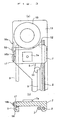
- Fig. 2 shows a schematic configuration of the optical pickup device embodying the invention in this mode.
- a disk accommodating section 100 has a plurality of trays arranged to be slidable in a direction perpendicular to the surface of the drawing, and a disk which the user wishes to play back is mounted on each of the trays.
- a spindle around which an optical pickup device 1 turns.
- the optical pickup device 1 is provided with a quadrilateral parallel link 6 formed of a screw shaft 2, a guide shaft 3, a first connecting plate 4 and a second connecting plate 5, and an optical pickup unit 7 which is screwed on to the screw shaft 2 and is linearly reciprocated by the rotation of the screw shaft 2 in its axial direction while being guided by the guide shaft 3.
- the optical pickup unit 7 is provided with a photo-unit 7a such as an objective lens or an optical detector, directed upward.
- the first connecting plate 4 of the parallel link 6 is fixed at a position relative to a base 10 at two points of fixed rotation shafts 8 and 9.
- the second connecting plate 5 is rotatably connected by floating rotation shafts 11 and 12 to the guide shaft 3 and the screw shaft 2, respectively.
- the fixed rotation shaft 8 rotatably holds one end of the guide shaft 3, while the fixed rotation shaft 9 is fixed to a chassis 13 holding the screw shaft 2, and connected to the rotation shaft of a driving motor 14, which is link driving means. Therefore, when the fixed rotation shaft 9 is turned by the driving motor 14, the chassis 13 oscillates pivoting on the first connecting plate 4.
- the metal plate-made chassis 13 has a cut portion 13a on the guide shaft 3 side toward a supporting point.
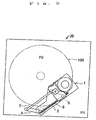
- the purpose of the cut portion is not to allow, when the optical pickup device 1 is in the escape position P1 as shown in Fig. 4, the chassis 13 to prevent the tray of the disk accommodating section 100 from shifting.
- a turntable 15 which is the means of turning the disk, is disposed, and a spindle motor (not shown) is arranged behind it.
- Figs. 3 show expanded views of the tip of the optical pickup device 1.
- the base end 16a of a lock spring 16, which is the locking means is fixed to a side of the disk accommodating section 100 at the tip of the chassis 13.
- the lock spring 16, which is a leaf spring, is corrugated, and the engagement of a convex 16b in the middle with an engaging hole 17 bored in a side of the optical pickup unit 7 serves to fix the optical pickup unit 7 to the chassis 13.
- This fixed position is located deeper than the starting position of the optical pickup unit 7 for recording or playing back, and the optical pickup unit 7 starts the operation for recording or playing back after moving out of this initial position.
- an engaging hook 18, which is fixing means is fixed to the under face of the optical pickup unit 7 and, by being snapped onto the guide shaft 3, which is in the working position, fixes the guide shaft 3.
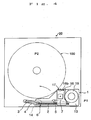
- the optical pickup device 1 In the state shown in Fig. 4, the optical pickup device 1 is in the escape position P1, and the parallel link 6 is folded by the driving motor 14 pivoting on the first connecting plate 4. In this state, the optical pickup unit 7 is locked by the engagement of the convex 16b of the lock spring 16 and the engaging hole 17 with each other.
- the parallel link 6 shifts in the same direction pivoting on the first connecting plate 4 to gradually widen the gap between the guide shaft 3 and the screw shaft 2 to reach the state shown in Fig. 5, and is further turned to be placed in the working position P2 shown in Fig. 2.
- the feed motor is reversed by a detection signal from the micro-switch, the optical pickup unit 7 shifts inward in the radial direction of the turntable 15, and the engaging hole 17 engages with the lock spring 16 to fix the optical pickup unit 7 in its initial position.
- the driving motor 14 is reversed by another detection signal from the micro-switch, and the chassis 13 shifts toward the escape position P1 shown in Fig. 4 and is stopped by still another detection signal from the micro-switch in the position shown in Fig. 4.
- the optical pickup unit 7 is held by the screw shaft 2 and the guide shaft 3 which are parallel to each other, the quadrilateral parallel link 6 is formed of the screw shaft 2, the guide shaft 3, the first connecting plate 4 and the second connecting plate 5, the chassis 13 holding the parallel link 6 and the turntable 15 is oscillated by the driving motor 14 pivoting on the first connecting plate 4, and the gap between the screw shaft 2 and the guide shaft 3 is narrowed in the escape position P1 in which the optical pickup device 1 is away from the disk accommodating section 100, no large escape space is needed in the escape position P1 of the optical pickup unit 7, and this enables the whole device to be reduced in size. Therefore, by applying this optical pickup device to the changer-type optical disk record/playback device 20, the depth in the direction of disk insertion can be made shallower, and this makes a further contribution to reducing the size of the optical disk record/playback device.
- the locking means using the lock spring 16 and the engaging hole 17 as well as the fixing means using the engaging hook 18 can be modified in various ways by use of other known features of the prior art.
- the quadrilateral parallel link is formed of the screw shaft, the guide shaft 3, and the two connecting plates in the foregoing embodiment, the parallelism between the screw shaft and the guide shaft can also be maintained by one connecting plate and guide shaft angle control means provided on this connecting plate instead of using two connecting plates.
- the parallel link is formed of the screw shaft, guide shaft and connecting means supporting the optical pickup unit and this parallel link is oscillated by link driving means in the optical pickup device pertaining to the invention, there can be provided a compact optical pickup device having the advantage that the width of the parallel link can be narrowed in the escape position and accordingly the escape space is compressed. It can be effectively applied to optical disk record/playback devices and the like reduced in size.
- the parallel link is constructed in a quadrilateral shape, the parallelism between the screw shaft and the guide shaft is maintained stable.
- the optical pickup device allows the guide shaft to be brought close to the screw shaft in the escape position and the width of the parallel link is thereby narrowed, the overall size of the device can be reduced.
- the parallel link can be held stable to enable the optical pickup unit to shift smoothly.
- the optical pickup unit since the optical pickup unit is fixed to the chassis and thereby made unable to shift when it is not working, the optical pickup unit can be held stable to prevent fluctuations in its characteristics.
- An optical disk record/playback device makes it possible to realize a compact optical disk record/playback device.
Abstract
Description
- The present invention relates to an optical pickup device and an optical disk record/playback device for recording or reproducing data onto or from an optical disk such as a compact disc(CD) or a digital versatile disc (DVD).
- A changer-type optical disk record/playback device, which is an optical disk record/playback device according to the prior art, is provided with a
disk accommodating section 100 having a plurality of trays arranged to be slidable in a direction perpendicular to the surface of the drawing as shown in Fig. 1, and a disk mounted on one or another of the trays is selected by driving the tray in the axial direction and positioned in its record/playback position. Outside thedisk accommodating section 100, anoptical pickup device 101 is selectively placed around aspindle 101 in an escape position P1 or a working position P2. Theoptical pickup device 101 is provided with achassis 103 fixed to thespindle 102, ascrew shaft 104 rotatably fixed to thechassis 103, aguide shaft 105 arranged on thechassis 103 in parallel to thescrew shaft 104, anoptical pickup 106 disposed slidably on thescrew shaft 104 and theguide shaft 105, and aturntable 107 for holding and turning a disk. Thescrew shaft 104 is turned by a feed motor (not shown). Theoptical pickup 106 is provided with a photo-unit 106a such as an objective lens or an optical detector, directed upward. - When the user gives the reference number of the desired disk tray, the pertinent tray in the
disk accommodating section 100 is selected, and the disk on the tray is placed in a prescribed record/playback position. Then, as the user presses the record/playback button, adriving motor 108 turns thespindle 102, and theoptical pickup device 101 shifts from the escape position P1 to the working position P2. The disk on the tray is held on theturntable 107, and turned by a spindle motor. Rotational driving of thescrew shaft 104 by the feed motor (not shown) causes theoptical pickup 106 to shift from the central part to the periphery of the disk to read signals recorded on, or to record signals onto, the disk. Upon completion of recording onto or playback of the disk, theoptical pickup 106 returns to its initial position, and theoptical pickup device 101 also returns to its escape position P1. - It is a trend prevalent in recent years to require such optical disk record/playback devices to be reduced in size, and attempts are being made to reduce the size and weight of the above-described configuration. The usual arrangement previously was to shift a disk stored in a disk accommodating section to the record/playback position and to accomplish recording or playing back with an optical pickup device fixed in position. The above-described configuration in which, conversely, the position of the disk accommodating section is fixed and the optical pickup device is shifted, the overall size of the optical disk record/playback device can be reduced, and attempts are continued for further reduction in size (see, for instance, the Japanese Published Unexamined Patent Application No. 2002-109810).
- However, the product of any such prior attempt at size reduction requires, when the optical pickup device escapes from the disk accommodating section, much of the movable range of the optical pickup device for its escape space, resulting in a problem of restricting any further reduction in device size.
- An object of the present invention, undertaken to solve this problem with the prior art, is to provide an optical disk record/playback device and an optical pickup device permitting reduction in space to be set aside for letting the optical pickup escape from a disk accommodating section and enabling the whole device to be reduced in size.
- An optical pickup device according to the invention has a configuration provided with an optical pickup unit which is linearly reciprocated by a screw shaft held by a chassis and driven and guided by a guide shaft arranged substantially in parallel to the screw shaft, a parallel link including the screw shaft, the guide shaft and connecting means of which one end is rotatably connected to the screw shaft and another end is rotatably connected to the guide shaft, and link driving means for oscillating the parallel link.
- In this configuration, oscillation of the parallel link by the link driving means pivoting on the connecting means enables the disk turning means held by the chassis to place a disk arranged in a disk accommodating section either in its working position for recording and playing back and an escape position away from the disk accommodating section. Furthermore, as the width of the parallel link is narrowed in the escape position, no large escape space is required, and the overall size of the device can be reduced.
- The aforementioned object and advantages of the present invention will become more apparent from the following description of a preferred embodiment thereof when taken in conjunction with accompanying drawings.
-
- Fig. 1 shows schematic plan of a conventional optical pickup device.
- Fig. 2 shows a plan of an optical pickup device, which is a preferred embodiment of the invention, in its working position P2.
- Fig. 3A shows an enlarged partial plan of the essential part of the optical pickup device, which is the preferred embodiment of the invention.
- Fig. 3B shows an enlarged partial section of the optical pickup device, which is the preferred embodiment of the invention.
- Fig. 4 shows a plan of the optical pickup device, which is the preferred embodiment of the invention, in its escape position P1.
- Fig. 5 shows a plan of the optical pickup device, which is the preferred embodiment of the invention, when in transit from the escape position P1 to the working position P2.
-
- The optical pickup device, which is the preferred embodiment of the invention, will be described below with reference to drawings. Fig. 2 shows a schematic configuration of the optical pickup device embodying the invention in this mode. Referring to Fig. 2, within a changer-type optical disk record/
playback device 20, a disk accommodatingsection 100 has a plurality of trays arranged to be slidable in a direction perpendicular to the surface of the drawing, and a disk which the user wishes to play back is mounted on each of the trays. Outside thedisk accommodating section 100, there is arranged a spindle around which an optical pickup device 1 turns. The optical pickup device 1 is provided with a quadrilateralparallel link 6 formed of ascrew shaft 2, aguide shaft 3, a first connectingplate 4 and a second connectingplate 5, and anoptical pickup unit 7 which is screwed on to thescrew shaft 2 and is linearly reciprocated by the rotation of thescrew shaft 2 in its axial direction while being guided by theguide shaft 3. Theoptical pickup unit 7 is provided with a photo-unit 7a such as an objective lens or an optical detector, directed upward. - The first connecting
plate 4 of theparallel link 6 is fixed at a position relative to abase 10 at two points offixed rotation shafts plate 5 is rotatably connected byfloating rotation shafts guide shaft 3 and thescrew shaft 2, respectively. Thefixed rotation shaft 8 rotatably holds one end of theguide shaft 3, while thefixed rotation shaft 9 is fixed to achassis 13 holding thescrew shaft 2, and connected to the rotation shaft of a drivingmotor 14, which is link driving means. Therefore, when thefixed rotation shaft 9 is turned by thedriving motor 14, thechassis 13 oscillates pivoting on the first connectingplate 4. The metal plate-madechassis 13 has acut portion 13a on theguide shaft 3 side toward a supporting point. The purpose of the cut portion is not to allow, when the optical pickup device 1 is in the escape position P1 as shown in Fig. 4, thechassis 13 to prevent the tray of thedisk accommodating section 100 from shifting. Toward the tip of thechassis 13, aturntable 15, which is the means of turning the disk, is disposed, and a spindle motor (not shown) is arranged behind it. - Figs. 3 show expanded views of the tip of the optical pickup device 1. Referring to Fig. 3A, the
base end 16a of alock spring 16, which is the locking means, is fixed to a side of thedisk accommodating section 100 at the tip of thechassis 13. Thelock spring 16, which is a leaf spring, is corrugated, and the engagement of a convex 16b in the middle with anengaging hole 17 bored in a side of theoptical pickup unit 7 serves to fix theoptical pickup unit 7 to thechassis 13. This fixed position is located deeper than the starting position of theoptical pickup unit 7 for recording or playing back, and theoptical pickup unit 7 starts the operation for recording or playing back after moving out of this initial position. Further as shown in Fig. 3B, anengaging hook 18, which is fixing means, is fixed to the under face of theoptical pickup unit 7 and, by being snapped onto theguide shaft 3, which is in the working position, fixes theguide shaft 3. - The operations of the optical pickup device configured as described above will be described below with reference to Fig. 2 through Fig. 5. In the state shown in Fig. 4, the optical pickup device 1 is in the escape position P1, and the
parallel link 6 is folded by the drivingmotor 14 pivoting on the first connectingplate 4. In this state, theoptical pickup unit 7 is locked by the engagement of the convex 16b of thelock spring 16 and theengaging hole 17 with each other. When thechassis 13 is turned counterclockwise from this state by thedriving motor 14, theparallel link 6 shifts in the same direction pivoting on the first connectingplate 4 to gradually widen the gap between theguide shaft 3 and thescrew shaft 2 to reach the state shown in Fig. 5, and is further turned to be placed in the working position P2 shown in Fig. 2. In this working position P2, the gap between theguide shaft 3 and thescrew shaft 2 is expanded to the maximum in theparallel link 6, and theguide shaft 3 is snapped into theengaging hook 18 as shown in Fig. 3B. A micro-switch senses the arrival of theparallel link 6 in this working position P2 and stops the turning of the drivingmotor 14. Then, a selected tray from thedisk accommodating section 100 shifts to the record/playback position, and the disk on that tray is mounted on theturntable 15. Theturntable 15 is turned by the spindle motor, and thescrew shaft 2 is turned by the feed motor to release theoptical pickup unit 7 from its initial position. As a result, thelock spring 16 and theengaging hole 17 are disengaged from each other, and theoptical pickup unit 7 shifts outward in the radial direction of theturntable 15 to enable signals to be recorded onto or reproduced from the disk on theturntable 15. - Upon completion of recording or playing back, the feed motor is reversed by a detection signal from the micro-switch, the
optical pickup unit 7 shifts inward in the radial direction of theturntable 15, and theengaging hole 17 engages with thelock spring 16 to fix theoptical pickup unit 7 in its initial position. Then, thedriving motor 14 is reversed by another detection signal from the micro-switch, and thechassis 13 shifts toward the escape position P1 shown in Fig. 4 and is stopped by still another detection signal from the micro-switch in the position shown in Fig. 4. - As described so far, since in the optical pickup device embodying the invention in this mode the
optical pickup unit 7 is held by thescrew shaft 2 and theguide shaft 3 which are parallel to each other, the quadrilateralparallel link 6 is formed of thescrew shaft 2, theguide shaft 3, the first connectingplate 4 and the second connectingplate 5, thechassis 13 holding theparallel link 6 and theturntable 15 is oscillated by the drivingmotor 14 pivoting on the first connectingplate 4, and the gap between thescrew shaft 2 and theguide shaft 3 is narrowed in the escape position P1 in which the optical pickup device 1 is away from thedisk accommodating section 100, no large escape space is needed in the escape position P1 of theoptical pickup unit 7, and this enables the whole device to be reduced in size. Therefore, by applying this optical pickup device to the changer-type optical disk record/playback device 20, the depth in the direction of disk insertion can be made shallower, and this makes a further contribution to reducing the size of the optical disk record/playback device. - In the embodiment of the invention described above, the locking means using the
lock spring 16 and the engaginghole 17 as well as the fixing means using the engaginghook 18 can be modified in various ways by use of other known features of the prior art. - Although the quadrilateral parallel link is formed of the screw shaft, the
guide shaft 3, and the two connecting plates in the foregoing embodiment, the parallelism between the screw shaft and the guide shaft can also be maintained by one connecting plate and guide shaft angle control means provided on this connecting plate instead of using two connecting plates. - As hitherto described, since the parallel link is formed of the screw shaft, guide shaft and connecting means supporting the optical pickup unit and this parallel link is oscillated by link driving means in the optical pickup device pertaining to the invention, there can be provided a compact optical pickup device having the advantage that the width of the parallel link can be narrowed in the escape position and accordingly the escape space is compressed. It can be effectively applied to optical disk record/playback devices and the like reduced in size.
- Further, because the parallel link is constructed in a quadrilateral shape, the parallelism between the screw shaft and the guide shaft is maintained stable.
- The optical pickup device according to the invention allows the guide shaft to be brought close to the screw shaft in the escape position and the width of the parallel link is thereby narrowed, the overall size of the device can be reduced.
- In the optical pickup device according to the invention, since the guide shaft is fixed by the fixing means provided on the chassis in the working position of the disk turning means, the parallel link can be held stable to enable the optical pickup unit to shift smoothly.
- In the optical pickup device according to the invention, since the optical pickup unit is fixed to the chassis and thereby made unable to shift when it is not working, the optical pickup unit can be held stable to prevent fluctuations in its characteristics.
- An optical disk record/playback device according to the invention makes it possible to realize a compact optical disk record/playback device.
- Although the present invention has been described with reference to a preferred embodiment thereof illustrated in accompanying drawings, obviously the invention can be readily altered or modified without deviating from its true spirit and scope. The invention would also cover such alterations and modifications.
Claims (6)
- An optical pickup device provided with an optical pickup unit which is linearly reciprocated by a screw shaft held by a chassis and driven and guided by a guide shaft arranged substantially in parallel to said screw shaft, a parallel link comprising said screw shaft, said guide shaft and connecting means of which one end is rotatably connected to said screw shaft and another end is rotatably connected to said guide shaft, and link driving means for oscillating said parallel link.
- The optical pickup device according to Claim 1, wherein said parallel link comprises said screw shaft, said guide shaft, first connecting means rotatably connected to one end of said screw shaft and to one end of said guide shaft, and second connecting means rotatably connected to another end of said screw shaft and to another end of said guide shaft, and said link driving means cause said parallel link to oscillate pivoting on the ends of said first connecting means.
- The optical pickup device according to claim 1, wherein said guide shaft can come close to and move away from said screw shaft.
- The optical pickup device according to claim 1 , further provided with fixing means for fixing said guide shaft to said chassis.
- The optical pickup device according to claim 1, further provided with locking means for fixing said optical pickup unit to said chassis.
- An optical disk record/playback device provided with the optical pickup device set forth in claim 1.
Applications Claiming Priority (2)
| Application Number | Priority Date | Filing Date | Title |
|---|---|---|---|
| JP2003394950 | 2003-11-26 | ||
| JP2003394950A JP3813607B2 (en) | 2003-11-26 | 2003-11-26 | Optical pickup device and optical disk recording / reproducing device |
Publications (3)
| Publication Number | Publication Date |
|---|---|
| EP1538622A2 true EP1538622A2 (en) | 2005-06-08 |
| EP1538622A3 EP1538622A3 (en) | 2007-10-24 |
| EP1538622B1 EP1538622B1 (en) | 2009-01-21 |
Family
ID=34463791
Family Applications (1)
| Application Number | Title | Priority Date | Filing Date |
|---|---|---|---|
| EP04027720A Expired - Fee Related EP1538622B1 (en) | 2003-11-26 | 2004-11-23 | Optical pickup device and optical disk record/playback device |
Country Status (5)
| Country | Link |
|---|---|
| US (1) | US7418723B2 (en) |
| EP (1) | EP1538622B1 (en) |
| JP (1) | JP3813607B2 (en) |
| CN (1) | CN100383867C (en) |
| DE (1) | DE602004019176D1 (en) |
Families Citing this family (7)
| Publication number | Priority date | Publication date | Assignee | Title |
|---|---|---|---|---|
| JP3825005B2 (en) * | 2003-02-06 | 2006-09-20 | 松下電器産業株式会社 | Disk unit |
| JP4641739B2 (en) * | 2004-05-10 | 2011-03-02 | アルパイン株式会社 | Disk unit |
| JP4472450B2 (en) * | 2004-07-15 | 2010-06-02 | パナソニック株式会社 | Optical disk device |
| JP4603478B2 (en) * | 2005-12-06 | 2010-12-22 | 株式会社日立製作所 | Optical disk device |
| WO2008078504A1 (en) * | 2006-12-22 | 2008-07-03 | Mitsubishi Electric Corporation | Recording medium reproducing apparatus |
| CN102566660B (en) * | 2010-12-13 | 2017-02-08 | 泰州市智谷软件园有限公司 | Portable electronic device with compact disc driver |
| US20130279319A1 (en) * | 2011-01-21 | 2013-10-24 | Mitsubishi Electric Corporation | Optical pickup device and optical disc device |
Citations (2)
| Publication number | Priority date | Publication date | Assignee | Title |
|---|---|---|---|---|
| US20010012260A1 (en) * | 1996-12-03 | 2001-08-09 | Sanyo Electric Co., Ltd | Disk player including a disk chucking mechanism and plate separation device |
| JP2002109810A (en) * | 2000-09-27 | 2002-04-12 | Alpine Electronics Inc | Changer type disk reproducing and/or recording device |
Family Cites Families (11)
| Publication number | Priority date | Publication date | Assignee | Title |
|---|---|---|---|---|
| US5243591A (en) * | 1990-04-23 | 1993-09-07 | Asahi Kogaku Kogyo Kabushiki Kaisha | Protecting a read/write head from damage |
| JP2859529B2 (en) * | 1993-12-15 | 1999-02-17 | シンワ株式会社 | Recording / reproducing method and apparatus for recording / reproducing disc |
| JP3514588B2 (en) * | 1996-08-23 | 2004-03-31 | アルパイン株式会社 | Disk unit |
| US6198719B1 (en) * | 1998-02-27 | 2001-03-06 | Nortel Networks Limited | Bi-orthogonal code division multiple access system |
| JP3978949B2 (en) * | 1999-09-29 | 2007-09-19 | ソニー株式会社 | Disc recording and / or playback device |
| JP2001184770A (en) * | 1999-12-27 | 2001-07-06 | Pioneer Electronic Corp | Recording medium reproducing device |
| US6505921B2 (en) | 2000-12-28 | 2003-01-14 | Eastman Kodak Company | Ink jet apparatus having amplified asymmetric heating drop deflection |
| US20030047388A1 (en) * | 2001-08-30 | 2003-03-13 | Faitel William M. | Scissors lifter drive apparatus |
| JP3825005B2 (en) * | 2003-02-06 | 2006-09-20 | 松下電器産業株式会社 | Disk unit |
| JP3958233B2 (en) * | 2003-03-06 | 2007-08-15 | 三菱電機株式会社 | Disk unit |
| US7072147B2 (en) * | 2003-06-20 | 2006-07-04 | Seagate Technology Llc | Hard drive actuator arm with reduced skew variation |
-
2003
- 2003-11-26 JP JP2003394950A patent/JP3813607B2/en not_active Expired - Fee Related
-
2004
- 2004-11-23 DE DE602004019176T patent/DE602004019176D1/en active Active
- 2004-11-23 US US10/995,706 patent/US7418723B2/en not_active Expired - Fee Related
- 2004-11-23 EP EP04027720A patent/EP1538622B1/en not_active Expired - Fee Related
- 2004-11-26 CN CNB2004100958197A patent/CN100383867C/en not_active Expired - Fee Related
Patent Citations (2)
| Publication number | Priority date | Publication date | Assignee | Title |
|---|---|---|---|---|
| US20010012260A1 (en) * | 1996-12-03 | 2001-08-09 | Sanyo Electric Co., Ltd | Disk player including a disk chucking mechanism and plate separation device |
| JP2002109810A (en) * | 2000-09-27 | 2002-04-12 | Alpine Electronics Inc | Changer type disk reproducing and/or recording device |
Also Published As
| Publication number | Publication date |
|---|---|
| CN100383867C (en) | 2008-04-23 |
| JP3813607B2 (en) | 2006-08-23 |
| EP1538622B1 (en) | 2009-01-21 |
| DE602004019176D1 (en) | 2009-03-12 |
| CN1627387A (en) | 2005-06-15 |
| EP1538622A3 (en) | 2007-10-24 |
| JP2005158149A (en) | 2005-06-16 |
| US20050114878A1 (en) | 2005-05-26 |
| US7418723B2 (en) | 2008-08-26 |
Similar Documents
| Publication | Publication Date | Title |
|---|---|---|
| US6901650B2 (en) | Adjusting method for an optical disc apparatus | |
| EP1371878A1 (en) | Feed screw driver and information recorder/reproducer | |
| US6880164B2 (en) | Support mechanism and feeding unit including same | |
| EP1538622B1 (en) | Optical pickup device and optical disk record/playback device | |
| US6735161B1 (en) | Recording-medium transfer device | |
| US20040255316A1 (en) | Device for traversing optical pickup of a disc drive | |
| JPH0731417Y2 (en) | Pickup feed mechanism for disc type recording medium reproducing device | |
| JP3946103B2 (en) | Clamp / alignment mechanism, information reproduction mechanism and information recording mechanism | |
| JPH11339348A (en) | Disk device | |
| US20020150020A1 (en) | Positional displacement compensating mechanism and recording medium playback device | |
| KR101058544B1 (en) | Disc cartridges and recording and / or playback devices | |
| JP4240840B2 (en) | Disk drive device | |
| JP2008165888A (en) | Optical disk drive and chassis structure | |
| JP2003091917A (en) | Disk drive device | |
| JP3867855B2 (en) | Optical disk playback device | |
| KR200336200Y1 (en) | Optical Pickup Loading Device | |
| JP3959808B2 (en) | Disk unit | |
| KR0146427B1 (en) | A swinging preventing device of mini disc player for a car | |
| JPH03102672A (en) | Disk player | |
| US20020024912A1 (en) | Positioning system for use in an information recording/reproducing apparatus | |
| KR101058858B1 (en) | Disc cartridge | |
| JP3553754B2 (en) | Disc player | |
| JP2002208203A (en) | Disk clamping device | |
| JPH1173744A (en) | Optical disk recording and/or reproducing device | |
| JPH0765485A (en) | Changer type disk reproducing device |
Legal Events
| Date | Code | Title | Description |
|---|---|---|---|
| PUAI | Public reference made under article 153(3) epc to a published international application that has entered the european phase |
Free format text: ORIGINAL CODE: 0009012 |
|
| AK | Designated contracting states |
Kind code of ref document: A2 Designated state(s): AT BE BG CH CY CZ DE DK EE ES FI FR GB GR HU IE IS IT LI LU MC NL PL PT RO SE SI SK TR |
|
| AX | Request for extension of the european patent |
Extension state: AL HR LT LV MK YU |
|
| PUAL | Search report despatched |
Free format text: ORIGINAL CODE: 0009013 |
|
| AK | Designated contracting states |
Kind code of ref document: A3 Designated state(s): AT BE BG CH CY CZ DE DK EE ES FI FR GB GR HU IE IS IT LI LU MC NL PL PT RO SE SI SK TR |
|
| AX | Request for extension of the european patent |
Extension state: AL HR LT LV MK YU |
|
| 17P | Request for examination filed |
Effective date: 20080110 |
|
| AKX | Designation fees paid |
Designated state(s): DE FR GB |
|
| GRAP | Despatch of communication of intention to grant a patent |
Free format text: ORIGINAL CODE: EPIDOSNIGR1 |
|
| RAP1 | Party data changed (applicant data changed or rights of an application transferred) |
Owner name: PANASONIC CORPORATION |
|
| GRAS | Grant fee paid |
Free format text: ORIGINAL CODE: EPIDOSNIGR3 |
|
| GRAA | (expected) grant |
Free format text: ORIGINAL CODE: 0009210 |
|
| AK | Designated contracting states |
Kind code of ref document: B1 Designated state(s): DE FR GB |
|
| REG | Reference to a national code |
Ref country code: GB Ref legal event code: FG4D |
|
| REF | Corresponds to: |
Ref document number: 602004019176 Country of ref document: DE Date of ref document: 20090312 Kind code of ref document: P |
|
| PLBE | No opposition filed within time limit |
Free format text: ORIGINAL CODE: 0009261 |
|
| STAA | Information on the status of an ep patent application or granted ep patent |
Free format text: STATUS: NO OPPOSITION FILED WITHIN TIME LIMIT |
|
| 26N | No opposition filed |
Effective date: 20091022 |
|
| REG | Reference to a national code |
Ref country code: GB Ref legal event code: 746 Effective date: 20091221 |
|
| PGFP | Annual fee paid to national office [announced via postgrant information from national office to epo] |
Ref country code: DE Payment date: 20091119 Year of fee payment: 6 |
|
| PGFP | Annual fee paid to national office [announced via postgrant information from national office to epo] |
Ref country code: FR Payment date: 20091123 Year of fee payment: 6 Ref country code: GB Payment date: 20091118 Year of fee payment: 6 |
|
| GBPC | Gb: european patent ceased through non-payment of renewal fee |
Effective date: 20101123 |
|
| REG | Reference to a national code |
Ref country code: FR Ref legal event code: ST Effective date: 20110801 |
|
| REG | Reference to a national code |
Ref country code: DE Ref legal event code: R119 Ref document number: 602004019176 Country of ref document: DE Effective date: 20110601 Ref country code: DE Ref legal event code: R119 Ref document number: 602004019176 Country of ref document: DE Effective date: 20110531 |
|
| PG25 | Lapsed in a contracting state [announced via postgrant information from national office to epo] |
Ref country code: FR Free format text: LAPSE BECAUSE OF NON-PAYMENT OF DUE FEES Effective date: 20101130 |
|
| PG25 | Lapsed in a contracting state [announced via postgrant information from national office to epo] |
Ref country code: GB Free format text: LAPSE BECAUSE OF NON-PAYMENT OF DUE FEES Effective date: 20101123 |
|
| PG25 | Lapsed in a contracting state [announced via postgrant information from national office to epo] |
Ref country code: DE Free format text: LAPSE BECAUSE OF NON-PAYMENT OF DUE FEES Effective date: 20110531 |