EP1538757A2 - Rate matching and channel interleaving for a communications system - Google Patents
Rate matching and channel interleaving for a communications system Download PDFInfo
- Publication number
- EP1538757A2 EP1538757A2 EP05290324A EP05290324A EP1538757A2 EP 1538757 A2 EP1538757 A2 EP 1538757A2 EP 05290324 A EP05290324 A EP 05290324A EP 05290324 A EP05290324 A EP 05290324A EP 1538757 A2 EP1538757 A2 EP 1538757A2
- Authority
- EP
- European Patent Office
- Prior art keywords
- data bits
- matrix
- interleaved
- bits
- data
- Prior art date
- Legal status (The legal status is an assumption and is not a legal conclusion. Google has not performed a legal analysis and makes no representation as to the accuracy of the status listed.)
- Granted
Links
Images

Classifications
-
- H—ELECTRICITY
- H03—ELECTRONIC CIRCUITRY
- H03M—CODING; DECODING; CODE CONVERSION IN GENERAL
- H03M13/00—Coding, decoding or code conversion, for error detection or error correction; Coding theory basic assumptions; Coding bounds; Error probability evaluation methods; Channel models; Simulation or testing of codes
- H03M13/27—Coding, decoding or code conversion, for error detection or error correction; Coding theory basic assumptions; Coding bounds; Error probability evaluation methods; Channel models; Simulation or testing of codes using interleaving techniques
- H03M13/2739—Permutation polynomial interleaver, e.g. quadratic permutation polynomial [QPP] interleaver and quadratic congruence interleaver
-
- H—ELECTRICITY
- H03—ELECTRONIC CIRCUITRY
- H03M—CODING; DECODING; CODE CONVERSION IN GENERAL
- H03M13/00—Coding, decoding or code conversion, for error detection or error correction; Coding theory basic assumptions; Coding bounds; Error probability evaluation methods; Channel models; Simulation or testing of codes
- H03M13/27—Coding, decoding or code conversion, for error detection or error correction; Coding theory basic assumptions; Coding bounds; Error probability evaluation methods; Channel models; Simulation or testing of codes using interleaving techniques
- H03M13/2703—Coding, decoding or code conversion, for error detection or error correction; Coding theory basic assumptions; Coding bounds; Error probability evaluation methods; Channel models; Simulation or testing of codes using interleaving techniques the interleaver involving at least two directions
- H03M13/271—Row-column interleaver with permutations, e.g. block interleaving with inter-row, inter-column, intra-row or intra-column permutations
-
- H—ELECTRICITY
- H03—ELECTRONIC CIRCUITRY
- H03M—CODING; DECODING; CODE CONVERSION IN GENERAL
- H03M13/00—Coding, decoding or code conversion, for error detection or error correction; Coding theory basic assumptions; Coding bounds; Error probability evaluation methods; Channel models; Simulation or testing of codes
- H03M13/27—Coding, decoding or code conversion, for error detection or error correction; Coding theory basic assumptions; Coding bounds; Error probability evaluation methods; Channel models; Simulation or testing of codes using interleaving techniques
- H03M13/275—Interleaver wherein the permutation pattern is obtained using a congruential operation of the type y=ax+b modulo c
-
- H—ELECTRICITY
- H03—ELECTRONIC CIRCUITRY
- H03M—CODING; DECODING; CODE CONVERSION IN GENERAL
- H03M13/00—Coding, decoding or code conversion, for error detection or error correction; Coding theory basic assumptions; Coding bounds; Error probability evaluation methods; Channel models; Simulation or testing of codes
- H03M13/27—Coding, decoding or code conversion, for error detection or error correction; Coding theory basic assumptions; Coding bounds; Error probability evaluation methods; Channel models; Simulation or testing of codes using interleaving techniques
- H03M13/276—Interleaving address generation
- H03M13/2764—Circuits therefore
-
- H—ELECTRICITY
- H03—ELECTRONIC CIRCUITRY
- H03M—CODING; DECODING; CODE CONVERSION IN GENERAL
- H03M13/00—Coding, decoding or code conversion, for error detection or error correction; Coding theory basic assumptions; Coding bounds; Error probability evaluation methods; Channel models; Simulation or testing of codes
- H03M13/27—Coding, decoding or code conversion, for error detection or error correction; Coding theory basic assumptions; Coding bounds; Error probability evaluation methods; Channel models; Simulation or testing of codes using interleaving techniques
- H03M13/2792—Interleaver wherein interleaving is performed jointly with another technique such as puncturing, multiplexing or routing
-
- H—ELECTRICITY
- H03—ELECTRONIC CIRCUITRY
- H03M—CODING; DECODING; CODE CONVERSION IN GENERAL
- H03M13/00—Coding, decoding or code conversion, for error detection or error correction; Coding theory basic assumptions; Coding bounds; Error probability evaluation methods; Channel models; Simulation or testing of codes
- H03M13/29—Coding, decoding or code conversion, for error detection or error correction; Coding theory basic assumptions; Coding bounds; Error probability evaluation methods; Channel models; Simulation or testing of codes combining two or more codes or code structures, e.g. product codes, generalised product codes, concatenated codes, inner and outer codes
- H03M13/2957—Turbo codes and decoding
-
- H—ELECTRICITY
- H03—ELECTRONIC CIRCUITRY
- H03M—CODING; DECODING; CODE CONVERSION IN GENERAL
- H03M13/00—Coding, decoding or code conversion, for error detection or error correction; Coding theory basic assumptions; Coding bounds; Error probability evaluation methods; Channel models; Simulation or testing of codes
- H03M13/63—Joint error correction and other techniques
- H03M13/635—Error control coding in combination with rate matching
-
- H—ELECTRICITY
- H04—ELECTRIC COMMUNICATION TECHNIQUE
- H04L—TRANSMISSION OF DIGITAL INFORMATION, e.g. TELEGRAPHIC COMMUNICATION
- H04L1/00—Arrangements for detecting or preventing errors in the information received
- H04L1/004—Arrangements for detecting or preventing errors in the information received by using forward error control
- H04L1/0041—Arrangements at the transmitter end
-
- H—ELECTRICITY
- H04—ELECTRIC COMMUNICATION TECHNIQUE
- H04L—TRANSMISSION OF DIGITAL INFORMATION, e.g. TELEGRAPHIC COMMUNICATION
- H04L1/00—Arrangements for detecting or preventing errors in the information received
- H04L1/004—Arrangements for detecting or preventing errors in the information received by using forward error control
- H04L1/0045—Arrangements at the receiver end
- H04L1/0052—Realisations of complexity reduction techniques, e.g. pipelining or use of look-up tables
-
- H—ELECTRICITY
- H04—ELECTRIC COMMUNICATION TECHNIQUE
- H04L—TRANSMISSION OF DIGITAL INFORMATION, e.g. TELEGRAPHIC COMMUNICATION
- H04L1/00—Arrangements for detecting or preventing errors in the information received
- H04L1/004—Arrangements for detecting or preventing errors in the information received by using forward error control
- H04L1/0056—Systems characterized by the type of code used
- H04L1/0067—Rate matching
- H04L1/0068—Rate matching by puncturing
-
- H—ELECTRICITY
- H04—ELECTRIC COMMUNICATION TECHNIQUE
- H04L—TRANSMISSION OF DIGITAL INFORMATION, e.g. TELEGRAPHIC COMMUNICATION
- H04L1/00—Arrangements for detecting or preventing errors in the information received
- H04L1/004—Arrangements for detecting or preventing errors in the information received by using forward error control
- H04L1/0056—Systems characterized by the type of code used
- H04L1/0071—Use of interleaving
Definitions
- This invention relates to rate matching and channel interleaving for a communications system.
- turbo coding parallel concatenated convolutional coding
- So-called 3rd generation CDMA (code division multiple access) wireless communications systems are also being developed which require a channel or inter-frame interleaver which operates to interleave or permute data in blocks corresponding to the radio frame duration, typically 10 ms.
- the channel interleaver either precedes or follows a rate matching function which serves to match various data rates to the radio frame rate, and which typically involves puncturing (omission) or repetition of data symbols, in this case data bits. It is desirable to distribute the omitted or repeated bits as evenly as possible, with as great a distance as possible between punctured or repeated bits in the de-interleaved frames, in a manner that is easy to implement and that is relatively independent of variables such as the frame size, number of frames, and puncturing rate.
- this invention provides a method of matching a rate of data bits, in a matrix of data bits interleaved by a predetermined interleaving process, to a desired rate by deletion of redundant data bits or repetition of data bits derived from the matrix, including the steps of: determining in a non-interleaved matrix of said data bits a pattern of bits to be deleted or repeated to provide said desired data rate; decoding an address of each bit in said pattern in a manner inverse to the interleaving process to produce a respective address of the bit in the matrix of interleaved data bits; and deleting or repeating the respective bit in the interleaved data bits in dependence upon the respective address.
- the invention also provides rate matching apparatus arranged for carrying out a method as recited above.
- the invention also provides a data interleaver arranged for carrying out this method.
- Yet another aspect of this invention relates to a method of shuffling interleaved and rate matched data streams in the manner described below with reference to Fig. 4 of the drawings, and to the recursive application of this method to more than two such data streams.
- a service multiplexer 10 which serves to multiplex together a plurality of data signal streams, referred to as main stream services or QoS (Quality of Service) channels, which are supplied via respective service blocks 12 only one of which is illustrated.
- QoS Quality of Service
- Each service block 12 is supplied at inputs 14 with a plurality of constituent input signals, which may for example comprise any of various types of signals such as voice, data, and multi-media signals.
- These input signals may have arbitrary transmission rates, frame sizes, and other parameters.
- the input signals have CRC (cyclic redundancy check) codes added in blocks 16 and are multiplexed together in a transport channel multiplexer 18.
- the multiplexed signals are segmented, for encoding, in a segmentation block 20, and the segmented signals are subjected to FEC (forward error correction) coding in FEC blocks 22.
- FEC forward error correction
- the encoded signals are multiplexed in a multiplexer 24.
- the multiplexed signals are subjected to rate matching (puncturing (deletion) of redundant data symbols (bits) or repetition of data symbols (bits)) in a block 26 to match the data rate to the radio communications rate (air rate) with radio frames of 10 ms duration.
- rate matching puncturing (deletion) of redundant data symbols (bits) or repetition of data symbols (bits)
- the data bits are interleaved in a first interleaver 28, which is referred to as a channel or inter-frame interleaver because it operates to permute blocks each of 10 ms of data bits.
- the interleaver 28 is shown following the rate matching block 26, as discussed further below the positions of these functions may be interchanged, the multiplexed signals from the multiplexer 24 being supplied to the channel interleaver 28, and the interleaved signals from the interleaver being supplied to the rate matching block 26.
- these functions may be in the order shown in Fig. 1 for downlink transmission of signals from a central station, and may be in the reversed order for uplink transmission of signals to the central station.
- the resulting rate matched and interleaved signals are segmented for radio frames and physical channels in segmentation blocks 30 and 32 respectively to produce the signals for multiplexing by the multiplexer 10.
- Signals output by the multiplexer 10 are interleaved by a second interleaver 34 the outputs of which are segmented and mapped to dedicated physical channels in a segmentation and mapping block 36 for communications via a CDMA radio communications path in known manner.
- the first interleaver 28 can have a performance that is sufficiently good to enable the second interleaver 34 to be omitted or reduced to a simple shuffling operation, for example as described below. This is desirable in particular because otherwise the second interleaver 34 has the potential to degrade the interleaving performed by each first interleaver 28, whereas each first interleaver 28 can be optimized for its particular rate matched data stream and QoS.
- the first interleaver 28 is implemented as an algebraic interleaver providing a good random spreading property.
- the multiple encoded bit blocks or data transport frames for each QoS channel are mapped into a 2-dimensional matrix and are subjected to linear congruential rules to permute the rows and columns of the matrix to implement the interleaving function.
- a maximum interleaving depth and time span can be determined by searching a set of best parameters.
- the interleaver consequently has a relatively simple form without disadvantages of known interleavers, such as requiring large memory sizes for look-up tables or inadequately accommodating the rate matching function.
- the interleaver can operate by equivalent control of read or write addressing of memory locations of a linear memory in which data bits are stored, without any actual movement of the stored bits among the memory locations.
- the interleaver 26 as described in the patent application referred to above operates to implement the following three steps:
- Step 1 can be slightly modified to accommodate different numbers of data transport frames with a given number of columns of the matrix.
- step 3 to read out ⁇ columns of the matrix per radio frame accordingly.
- the row permutation parameter ⁇ r is chosen to be the largest prime number less than ⁇ N r /log 2 (log 2 (N r )) ⁇
- the column permutation parameter ⁇ c is chosen to be the largest prime number less than ⁇ N c ⁇
- the function f r (k) 2k+[N c +1]mod2.
- the symbols ⁇ ⁇ refer to rounding down to an integer
- the symbols ⁇ refer to rounding up to an integer.
- [N r +1]mod2 is zero when N r is odd and is one when N r is even
- [N c +1]mod2 is zero when N c is odd and is one when N c is even, so that these parts of the functions f c (l) and f r (k) are simply the addition of one when the respective number N r or N c is even.
- the rate matching punctures (deletes) redundant data bits (which are present as a result of the FEC encoding blocks 22) in the event that the data transport frame size is larger than the radio frame size, a maximum puncturing ratio being 20% of the transport frame size.
- the data transport frame size is smaller than the radio frame size, bits of the transport frame are repeated to achieve the rate matching.
- the rate matching is desired as far as possible to maximize the separation distances between the punctured bits and to equalize the number of punctured bits in each radio frame, i.e. to distribute the punctured bits uniformly among the radio frames with maximum separation.
- a known rate matching method as shown in Fig. 2 can be used.
- bit repetition y ⁇ 0, shown at the right in Fig. 2
- puncturing y>0, shown at the left in Fig. 2
- a parameter e is initialized to a starting offset e os which is determined in any desired manner for the particular radio frame, and a row counter r is initialized to 1.
- a row counter r is initialized to 1.
- a subsequent decision block 45 it is determined whether e ⁇ 0, and if so the bit in the row r is punctured at a block 46, the value of e is increased by 2N r in a block 47, the row counter r is increased by 1 in a block 48, and a return is made to the decision block 43.
- a negative decision at the block 45 i.e. e>0
- a negative decision at the block 43 i.e. r>N r ) indicates that the end of the frame has been reached, and accordingly the sequence ends at the stop block 41.
- the rate matching block 26 follows the channel interleaver 28
- the rate matching is carried out on the permuted (interleaved) bit stream and the problem of rate matching is considerably more complicated.
- the requirements of the channel interleaving and rate matching processes are not consistent.
- the design of an appropriate, and desirably optimized, rate matching pattern of punctured or repeated bits within the matrix of bits after the channel interleaving process represents a very complex or impractical task.
- This invention avoids this problem by providing an appropriate, and desirably optimized, rate matching pattern of punctured or repeated bits for the matrix before interleaving, and using a de-interleaving or decoding process to determine corresponding bits to be punctured or repeated at the output of the channel interleaver.
- This process is facilitated by the fact that the de-interleaving, or decoding, process can be implemented by exactly the same structure as the interleaving process, as further described below.
- the following description refers to the matrix of bits before interleaving (or after de-interleaving) as the natural matrix NM, and to the matrix of bits after interleaving as the randomized matrix RM.
- Fig. 3 illustrates an implementation of a channel interleaver 28 and rate matching block 26 in accordance with an embodiment of this invention.
- the interleaver 26 includes a working memory 50 with two halves, alternately used in known manner for writing into and reading from the memory, each for storing the N r N c data bits represented in the matrix as described above, these data bits being written into the memory linearly corresponding to the row-by-row organization of the matrix.
- a modulo-N r row counter 51 is responsive to a clock signal CLK to provide a count representing the row index k, and a carry output of this counter 51 is supplied to a modulo-N c column counter 52 to provide a count representing the column index 1.
- the counts k and l of the counters 51 and 52 are supplied to an address encoder 53 shown within a dashed line box in Fig. 3. More specifically, the count of the column counter 53 is supplied to multipliers 54 and 55 which are also supplied with the parameters ⁇ c and m respectively to produce products representing ⁇ c l and ml respectively, and the count of the row counter 51 is supplied to multipliers 56 and 57 which are also supplied with the integer 2 and the parameter ⁇ r respectively to produce products representing 2k and ⁇ r k respectively.
- An adder 58 adds the outputs of the multipliers 54 and 56 and selectively adds 1 or 0 depending upon whether N c is even or odd respectively, and the output of the adder 58 is reduced to modulo-N c form by a modulo function 59 to complete the column permutation function described above.
- An adder 60 adds the outputs of the multipliers 55 and 57 and selectively adds 1 or 0 depending upon whether N r is even or odd respectively, and the output of the adder 60 is reduced to modulo-N r form by a modulo function 61 to complete the row permutation function described above.
- Each of the modulo functions 59 and 61 can comprise comparison and subtraction functions.
- Outputs of the functions 59 and 61 are combined in a read address combiner 62 to produce an address for reading the respective data bit in its interleaved sequence from the memory 50.
- the read address is supplied to the memory 50 via a switch 63 which is provided as described below.
- the address combiner 62 can simply combine the output of the modulo function 61 as the least significant bits, and the output of the modulo function 59 as the most significant bits, of the read address for the memory 50; equivalently the output of the function 61 is added by the address combiner 62 to N r times the output of the function 59.
- the interleaver 28 of Fig. 3 also includes a decoder 64 which detects these memory locations in the read address output of the address combiner 62, and upon such detection opens the switch 63 to prevent reading of data from the memory 50 in respect of these locations.
- the interleaver 28 of Fig. 3 further includes a FIFO (first-in, first-out) memory 65, clocked by the clock signal CLK, via which the interleaved data bits are supplied to an output line 66 of the interleaver, the FIFO 65 being pre-filled at the start of each interleaving operation and having a size (e.g. up to N c ) sufficient to allow for the non-read, and hence omitted, memory locations.
- a FIFO first-in, first-out
- the interleaved data bits on the line 66 are supplied to the rate matching block or function 26 also illustrated in Fig. 3.
- This rate matching function comprises a rate matching address generator 70 which is also supplied with the clock signal CLK, an address separator 71, an address decoder 72, a buffer or store 73, comparators 74, and a data bit selector 75 providing a rate matched data output on a line 76.
- the rate matching function 26 may also include a FIFO or other buffer (not shown) for providing a constant rate of data bits from the output line 76.
- the rate matching address generator 70 generates at its output, as described further below, the address in the natural matrix NM of each punctured or repeated bit in accordance with the puncturing or repetition pattern which is determined for this process. This address is separated into most significant and least significant components by the address separator 71, whose operation is inverse to that of the read address combiner 62 described above. Thus if the number of rows N r is a power of two, then the address separator 71 can simply separate the address bits output by the generator 70 into most significant bits and least significant bits; equivalently the address from the generator 70 is divided by N r to produce an integer quotient and a remainder which constitute the two outputs of the address separator 71.
- the address decoder 72 performs the inverse function of the address encoder 53.
- the structure of the de-interleaver can be exactly the same as the structure of the interleaver, and correspondingly the address decoder 72 is exactly the same as the address encoder 53. Accordingly, the detailed structure of the address decoder 72 is not illustrated in Fig. 3, it being identical to the structure of the address encoder 53 as shown in Fig. 3. It can be appreciated that this same-structure characteristic of the complementary operations for interleaving and de-interleaving provides a substantial advantage and simplification in implementing these functions.
- the outputs of the address decoder 72 are buffered in the store 73, and the buffered outputs from the store are compared in the comparators 74 with the current counts k and l of the row counter 51 and column counter 52 respectively of the channel interleaver 28, to provide a selector control signal on a line 77 with a predetermined state when the compared values are the same.
- the selector control signal is thus produced on the line 77 with this state at each time that a bit on the line 66 is to be punctured or repeated.
- the control signal on the line 77 controls the selector 75 to supply to its output line 76, synchronously as determined by the clock signal CLK, a bit from the line 66 supplied to a middle one (as shown in Fig. 3) of three inputs of the selector 75.
- the control signal on the line 77 instead controls the selector 75 to supply to its output line a bit from either its upper input or its lower input (as shown in Fig. 3), depending upon whether bits are to be repeated or punctured respectively, as determined by a further control input P/R to the selector 75.
- the upper input of the selector 75 is connected to the output line 76 to provide for bit repetition, and the lower input of the selector 75 is illustrated as having no connection to provide for bit puncturing.
- a constant output data bit rate for the interleaved and rate matched data bits is provided by a buffer (not shown) to which data bits on the output line 76 are supplied.
- the rate matching address generator 70 can simply determine the desired pattern of punctured or repeated bits in terms of the normal matrix addresses in the manner described above with reference to Fig. 2, using the single parameter e os determined in a desired manner to optimize this pattern.
- Table 1 illustrates entry of the 80 data bits, numbered 0 to 79, row by row in a 10 by 8 natural matrix with the row index k from 1 to 10 and the column index l from 1 to 8: 1 1 2 3 4 5 6 7 8 k 1 0 1 2 3 4 5 6 7 2 8 9 10 11 12 13 14 15 3 16 17 18 19 20 21 22 23 4 24 25 26 27 28 29 30 31 5 32 33 34 35 36 37 38 39 6 40 41 42 43 44 45 46 47 7 48 49 50 51 52 53 54 55 8 56 57 58 59 60 61 62 63 9 64 65 66 67 68 69 70 71 10 72 73 74 75 76 77 78 79
- the channel interleaving as described above produces a randomized matrix as shown by the following Table 2: 1 1 2 3 4 5 6 7 8 k 1 57 40 79 62 45 28 11 74 2 35 18 1 64 23 6 69 52 3 13 76 59 42 25 8 47 30 4 71 54 37 20 3 66 49 32 5 73 56 15 78 61 44 27 10 6 51 34 17 0 39 22 5 68 7 29 12 75 58 41 24 63 46 8 7 70 53 36 19 2 65 48 9 9 72 31 14 77 60 43 26 10 67 50 33 16 55 38 21 4
- the rate matching as described above then punctures 16 bits, 2 from each column of the randomized matrix, in a pattern produced by the rate matching algorithm to give a punctured randomized matrix as shown by the following Table 3: 1 1 2 3 4 5 6 7 8 k 1 57 40 79 62 45 28 74 2 35 18 1 23 6 69 52 3 13 76 59 42 8 30 4 71 37 20 3 66 49 5 73 56 15 78 44 27 10 6 51 17 0 39 22 5 7 12 58 41 24 63 46 8 7 70 53 36 19 65 48 9 72 14 77 60 43 26 10 67 50 33 55 21 4
- the channel interleaved and rate matched data bits are derived column by column from Table 3, i.e., with the order [57, 35, ..., 51, 7, 67, 40, ..., 26, 4].
- the punctured bits are 2, 9, 11, 16, 25, 29, 31, 32, 34, 38, 47, 54, 61, 64, 68, and 75, for which the maximum puncture distance is 9 (25 - 16) and the minimum puncture distance is 1 (32-31); this small minimum puncture distance indicates that this particular example is not optimum, a larger minimum puncture distance being desirable. It can be appreciated that numerous other determinations of the parameters, and in particular of the parameter e os , can be provided to optimize the puncturing process.
- the second interleaver 34 it is desirable for operation of the second interleaver 34 not to degrade the performance achieved as a result of the first interleaver 28, and to this end it is advantageous for the second interleaver 34 to be reduced to a simple shuffling operation, which interleaves data streams with different QoS while retaining the spreading properties achieved by the first interleaver 28 for each QoS data stream.
- Fig. 4 shows a flow chart of a bit shuffling algorithm which can be used advantageously to interleave bits of two data streams of interleaved radio frames provided as described above from respective service blocks 12 provided via the service multiplexer 10 in Fig. 1.
- Fig. 4 illustrates how bits of the stream TQ 2 are inserted into the stream TQ 1 .
- a parameter e is initialized to N 1 and a counter r is initialized to 1.
- a block 83 it is determined whether r ⁇ N 1 and, if so, in a block 84 the value of e is reduced by 2N 2 .
- a subsequent decision block 85 it is determined whether e ⁇ 0, and if so at a block 86 the next bit in the stream TQ 2 is inserted into the stream TQ 1 , the value of e is increased by 2N 1 in a block 87, the counter r is increased by 1 in a block 88, and a return is made to the decision block 83.
- a negative decision at the block 85 i.e.
- e>0 results in a return to the block 83 via the block 88 to increment the counter r without any bit insertion or change in the value of e.
- a negative decision at the block 83 indicates that the end of the frame has been reached, and accordingly the sequence ends at a stop block 81.
- the puncturing of bits to achieve the desired rate matching is applied to data bits which have redundancy due to the FEC encoding provided by the encoders 22.
- One preferred form of encoding is so-called turbo (parallel concatenated convolutional) coding, in which the encoded data bits comprise the input data bits themselves, referred to as systematic data bits S, and parity bits P1 and P2 provided by convolutional coders operating on the input data bits and on interleaved input data bits.
- the parity bits P1 and P2 are typically punctured within the turbo coder to provide a desired rate turbo coder.
- Fig. 5 illustrates a modification of part of the arrangement of Fig. 1 for channel interleaving and rate matching of data encoded by turbo coding.
- a turbo coder constituting one of the FEC encoders 22 is shown within a dashed line box 90 and, as is well known, comprises a turbo code interleaver 91 which interleaves input data bits, and two convolutional coders 92 which operate on the input data bits before and after interleaving to produce parity bits P1 and P2, the input data bits also being supplied to the coder outputs as systematic bits S.
- a puncturing block may also be present to select only some of the parity bits P1 and P2 for supply to the coder outputs.
- Fig. 5 illustrates that individual channel interleavers 93 are provided for the systematic bit stream and the parity bit stream.
- there are three channel interleavers 93 but it can be appreciated that the streams of parity bits P1 and P2 can be combined and interleaved together, so that only two channel interleavers are provided, one for the systematic bit stream and the other for the parity bit stream.
- Further inputs to the channel interleavers 93 in Fig. 5 indicate the multiplexing of systematic and parity bit streams, respectively, for multiple channels, corresponding to the multiplexer 24 in Fig. 1.
- the rate matching function which follows the channel interleavers 93, is shown within a dashed line box 94.
- a puncturing function 95 is applied only to the channel-interleaved parity bit streams, whereas a repetition function 96 can be provided to the parity and systematic bit streams, a selector 97 being illustrated to couple the channel-interleaved bits accordingly.
- the puncturing and repetition can be as described above. It can be appreciated that the illustration in Fig. 5 in this respect is intended diagrammatically to represent the principle that puncturing is not applied to the systematic bits, rather than showing an actual implementation of the rate matching function. It can be appreciated, for example, that puncturing or repetition, as required, could be applied only to the parity bit streams to provide the desired rate matching, without any puncturing or repetition of the systematic bit stream.
Abstract
Description
- This invention relates to rate matching and channel interleaving for a communications system.
- It is well known to perform interleaving of data in a communications system using forward error correction (FEC) in order, on deinterleaving, to distribute errors to facilitate their correction. Typically, such interleaving uses a block interleaver to interleave blocks of data. So-called turbo coding (parallel concatenated convolutional coding) uses an interleaver between inputs to two convolutional coders which produce respective parity bits from the input data before and after interleaving. With increasing attention being given to the use of turbo coding, particularly in wireless communications systems, attention has also been given to the form of the interleaver.
- So-called 3rd generation CDMA (code division multiple access) wireless communications systems are also being developed which require a channel or inter-frame interleaver which operates to interleave or permute data in blocks corresponding to the radio frame duration, typically 10 ms. In such systems the channel interleaver either precedes or follows a rate matching function which serves to match various data rates to the radio frame rate, and which typically involves puncturing (omission) or repetition of data symbols, in this case data bits. It is desirable to distribute the omitted or repeated bits as evenly as possible, with as great a distance as possible between punctured or repeated bits in the de-interleaved frames, in a manner that is easy to implement and that is relatively independent of variables such as the frame size, number of frames, and puncturing rate.
- Canadian patent application No. 2,268,283 filed March 19, 1999 in the names of Wen Tong et al., entitled "Data Interleaver And Method Of Interleaving Data", describes and claims a method of interleaving data and a data interleaver which advantageously can be used to provide the channel interleaving referred to above. The present invention is concerned with rate matching in a manner which can be used with particular advantage for data after such channel interleaving, but which is also applicable to other forms of interleaved data. This invention also provides improvements in and further applications of such channel interleaving.
- According to one aspect, this invention provides a method of matching a rate of data bits, in a matrix of data bits interleaved by a predetermined interleaving process, to a desired rate by deletion of redundant data bits or repetition of data bits derived from the matrix, including the steps of: determining in a non-interleaved matrix of said data bits a pattern of bits to be deleted or repeated to provide said desired data rate; decoding an address of each bit in said pattern in a manner inverse to the interleaving process to produce a respective address of the bit in the matrix of interleaved data bits; and deleting or repeating the respective bit in the interleaved data bits in dependence upon the respective address.
- It is particularly advantageous, and may be necessary in practice, for the address decoding to be performed in the same manner as a coding of addresses for producing the interleaved data bits from the non-interleaved matrix of said data bits. This is facilitated in preferred embodiments of the method of the invention by the interleaving process comprising permuting rows and columns of a matrix of Nr rows and Nc columns, in which data bits to be interleaved are represented row by row, in accordance with:
Row Permutation Ir(k)=[αrk+fc(l)]modNr Column Permutation Ic(l)=[αcl+fr(k)]modNc - It is currently considered optimum to choose fc(l)=ml+[Nr+1]mod2, where m is an integer, m approximately equal to Nr/Nc, fr(k)=2k+[Nc+1]mod2, and αr as the largest prime number less than Nr/log2(log2(Nr)).
- The invention also provides rate matching apparatus arranged for carrying out a method as recited above.
- Another aspect of this invention provides a method of interleaving data bits comprising permuting rows and columns of a matrix of Nr rows and Nc columns, in which data bits to be interleaved are represented row by row, in accordance with:
Row Permutation Ir(k)=[αrk+fc(l)]modNr Column Permutation Ic(l)=[αcl+fr(k)]modNc column index 1, αc is an integer, fr(k)=2k+[Nc+1]mod2, and mod2, modNr and modNc represent modulo-2, modulo-Nr, and modulo-Nc arithmetic respectively, interleaved data bits being derived from the matrix column by column. - The invention also provides a data interleaver arranged for carrying out this method.
- Yet another aspect of this invention relates to a method of shuffling interleaved and rate matched data streams in the manner described below with reference to Fig. 4 of the drawings, and to the recursive application of this method to more than two such data streams.
- The invention will be further understood from the following description with reference to the accompanying drawings, in which:
- Fig. 1 illustrates a known arrangement for service multiplexing and channel interleaving in a 3rd generation CDMA communications system;
- Fig. 2 is a flow chart relating to a known rate matching algorithm;
- Fig. 3 illustrates an implementation of an interleaver and a rate matching arrangement in accordance with an embodiment of this invention;
- Fig. 4, which is on the same sheet as Fig. 2, is a flow chart relating to shuffling for a second stage of interleaving in the arrangement of Fig. 1; and
- Fig. 5 illustrates a modification of part of the arrangement of Fig. 1 for channel interleaving and rate matching of data encoded by turbo (parallel concatenated convolutional) coding.
-
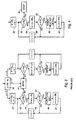
- Referring to Fig. 1, there is illustrated a known arrangement for service multiplexing and channel interleaving in a 3rd generation CDMA radio communications system. The arrangement includes a
service multiplexer 10 which serves to multiplex together a plurality of data signal streams, referred to as main stream services or QoS (Quality of Service) channels, which are supplied viarespective service blocks 12 only one of which is illustrated. Eachservice block 12 is supplied atinputs 14 with a plurality of constituent input signals, which may for example comprise any of various types of signals such as voice, data, and multi-media signals. These input signals may have arbitrary transmission rates, frame sizes, and other parameters. The input signals have CRC (cyclic redundancy check) codes added inblocks 16 and are multiplexed together in atransport channel multiplexer 18. The multiplexed signals are segmented, for encoding, in asegmentation block 20, and the segmented signals are subjected to FEC (forward error correction) coding inFEC blocks 22. The encoded signals are multiplexed in amultiplexer 24. - The multiplexed signals are subjected to rate matching (puncturing (deletion) of redundant data symbols (bits) or repetition of data symbols (bits)) in a
block 26 to match the data rate to the radio communications rate (air rate) with radio frames of 10 ms duration. Primarily in order to separate adjacent bits to reduce the adverse effects of errors due to fading in the radio channel, the data bits are interleaved in afirst interleaver 28, which is referred to as a channel or inter-frame interleaver because it operates to permute blocks each of 10 ms of data bits. Although in Fig. 1 theinterleaver 28 is shown following therate matching block 26, as discussed further below the positions of these functions may be interchanged, the multiplexed signals from themultiplexer 24 being supplied to thechannel interleaver 28, and the interleaved signals from the interleaver being supplied to therate matching block 26. For example, these functions may be in the order shown in Fig. 1 for downlink transmission of signals from a central station, and may be in the reversed order for uplink transmission of signals to the central station. - Following the
functions segmentation blocks multiplexer 10. Signals output by themultiplexer 10 are interleaved by asecond interleaver 34 the outputs of which are segmented and mapped to dedicated physical channels in a segmentation andmapping block 36 for communications via a CDMA radio communications path in known manner. - The
first interleaver 28 can have a performance that is sufficiently good to enable thesecond interleaver 34 to be omitted or reduced to a simple shuffling operation, for example as described below. This is desirable in particular because otherwise thesecond interleaver 34 has the potential to degrade the interleaving performed by eachfirst interleaver 28, whereas eachfirst interleaver 28 can be optimized for its particular rate matched data stream and QoS. - Accordingly, the
first interleaver 28 is implemented as an algebraic interleaver providing a good random spreading property. The multiple encoded bit blocks or data transport frames for each QoS channel are mapped into a 2-dimensional matrix and are subjected to linear congruential rules to permute the rows and columns of the matrix to implement the interleaving function. A maximum interleaving depth and time span can be determined by searching a set of best parameters. The interleaver consequently has a relatively simple form without disadvantages of known interleavers, such as requiring large memory sizes for look-up tables or inadequately accommodating the rate matching function. - Although the following description refers to rows and columns of a matrix, it should be understood that this is for convenience and clarity, that the rows and columns can be interchanged without changing the function of the interleaver, and that in practice and as described below the interleaver can operate by equivalent control of read or write addressing of memory locations of a linear memory in which data bits are stored, without any actual movement of the stored bits among the memory locations.
- The
interleaver 26 as described in the patent application referred to above operates to implement the following three steps: - 1. Represent a number Nc of encoded blocks of data bits each of length Nr data bits as a matrix of Nr rows and Nc columns.
- 2. Permute the rows and columns of the matrix in
accordance with:
Row Permutation Ir(k)=[αrk+fc(l)]modNr Column Permutation Ic(l)=[αcl+fr(k)]modNc - 3. Derive interleaved data bits from the matrix column by column.
-
-
Step 1 can be slightly modified to accommodate different numbers of data transport frames with a given number of columns of the matrix. For example the matrix can have Nc=8 columns for Nc/γ data transport frames where γ=1, 2, 4, or 8, the matrix having Nr/γ rows accordingly, with a consequent modification of step 3 to read out γ columns of the matrix per radio frame accordingly. For simplicity in the description below, it is assumed that γ=1 with Nc=8. - For
step 2, the row permutation parameter αr is chosen to be the largest prime number less than └Nr/log2(log2(Nr))┘, the column permutation parameter αc is chosen to be the largest prime number less than └Nc┘, the function fc(l)=ml+[Nr+1]mod2, where m is an integer equal to ┌Nr/Nc┐, and the function fr(k)=2k+[Nc+1]mod2. The symbols └ ┘ refer to rounding down to an integer, and the symbols ┌┐ refer to rounding up to an integer. It can be appreciated that [Nr+1]mod2 is zero when Nr is odd and is one when Nr is even, and that [Nc+1]mod2 is zero when Nc is odd and is one when Nc is even, so that these parts of the functions fc(l) and fr(k) are simply the addition of one when the respective number Nr or Nc is even. - As indicated above, the rate matching punctures (deletes) redundant data bits (which are present as a result of the FEC encoding blocks 22) in the event that the data transport frame size is larger than the radio frame size, a maximum puncturing ratio being 20% of the transport frame size. Conversely, if the data transport frame size is smaller than the radio frame size, bits of the transport frame are repeated to achieve the rate matching. The rate matching is desired as far as possible to maximize the separation distances between the punctured bits and to equalize the number of punctured bits in each radio frame, i.e. to distribute the punctured bits uniformly among the radio frames with maximum separation.
- In the case where the
rate matching block 26 precedes thechannel interleaver 28 as shown in Fig. 1, a known rate matching method as shown in Fig. 2 can be used. - Referring to Fig. 2, for each radio frame of segmentation size Ni bits, in a
block 40 an integer y is determined as y=Nr-Ni, y being greater than zero (positive) in the event that puncturing is required, being less than zero (negative) in the event that repetition of |y| bits is required, and being zero if no puncturing or repetition is required, astop block 41 being reached in the latter event. As the steps shown in Fig. 2 are substantially the same for bit repetition (y<0, shown at the right in Fig. 2) as for puncturing (y>0, shown at the left in Fig. 2), except for the use of |y| and repetition instead of y and puncturing, only the case of puncturing is described in detail below. - If y>0, puncturing of y of the Nr bits of the transport frame is required to produce the Ni bits of the radio frame. In this case in a block 42 a parameter e is initialized to a starting offset eos which is determined in any desired manner for the particular radio frame, and a row counter r is initialized to 1. In a
block 43, it is determined whether r≤Nr and, if so, in ablock 44 the value of e is reduced by 2y. In asubsequent decision block 45 it is determined whether e≤0, and if so the bit in the row r is punctured at ablock 46, the value of e is increased by 2Nr in ablock 47, the row counter r is increased by 1 in ablock 48, and a return is made to thedecision block 43. A negative decision at the block 45 (i.e. e>0) results in a return to theblock 43 via theblock 48 to increment the row counter r without any puncturing or change in the value of e. A negative decision at the block 43 (i.e. r>Nr) indicates that the end of the frame has been reached, and accordingly the sequence ends at thestop block 41. - However, in the case where the
rate matching block 26 follows thechannel interleaver 28, the rate matching is carried out on the permuted (interleaved) bit stream and the problem of rate matching is considerably more complicated. Generally, the requirements of the channel interleaving and rate matching processes are not consistent. - More particularly, the design of an appropriate, and desirably optimized, rate matching pattern of punctured or repeated bits within the matrix of bits after the channel interleaving process represents a very complex or impractical task. This invention avoids this problem by providing an appropriate, and desirably optimized, rate matching pattern of punctured or repeated bits for the matrix before interleaving, and using a de-interleaving or decoding process to determine corresponding bits to be punctured or repeated at the output of the channel interleaver. This process is facilitated by the fact that the de-interleaving, or decoding, process can be implemented by exactly the same structure as the interleaving process, as further described below. For convenience and clarity, the following description refers to the matrix of bits before interleaving (or after de-interleaving) as the natural matrix NM, and to the matrix of bits after interleaving as the randomized matrix RM.
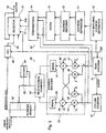
- Fig. 3 illustrates an implementation of a
channel interleaver 28 andrate matching block 26 in accordance with an embodiment of this invention. As illustrated in Fig. 3, theinterleaver 26 includes a workingmemory 50 with two halves, alternately used in known manner for writing into and reading from the memory, each for storing the NrNc data bits represented in the matrix as described above, these data bits being written into the memory linearly corresponding to the row-by-row organization of the matrix. A modulo-Nr row counter 51 is responsive to a clock signal CLK to provide a count representing the row index k, and a carry output of thiscounter 51 is supplied to a modulo-Nc column counter 52 to provide a count representing thecolumn index 1. The counts k and l of thecounters address encoder 53 shown within a dashed line box in Fig. 3. More specifically, the count of thecolumn counter 53 is supplied tomultipliers row counter 51 is supplied tomultipliers integer 2 and the parameter αr respectively to produce products representing 2k and αrk respectively. Anadder 58 adds the outputs of themultipliers adder 58 is reduced to modulo-Nc form by amodulo function 59 to complete the column permutation function described above. Anadder 60 adds the outputs of themultipliers adder 60 is reduced to modulo-Nr form by amodulo function 61 to complete the row permutation function described above. Each of the modulo functions 59 and 61 can comprise comparison and subtraction functions. Outputs of thefunctions read address combiner 62 to produce an address for reading the respective data bit in its interleaved sequence from thememory 50. As illustrated in Fig. 3, the read address is supplied to thememory 50 via aswitch 63 which is provided as described below. - If the number of rows Nr is a power of two, then the
address combiner 62 can simply combine the output of themodulo function 61 as the least significant bits, and the output of themodulo function 59 as the most significant bits, of the read address for thememory 50; equivalently the output of thefunction 61 is added by theaddress combiner 62 to Nr times the output of thefunction 59. - It may be desired to interleave data bits in arbitrary-sized frames that are not an integer multiple of Nc. In this case, the number of rows of the matrix is selected to accommodate all of the data bits to be interleaved, and the last few (less than Nc) memory locations in the working
memory 50 are not written into. In order to omit the data bits of these memory locations from the interleaved data bits, theinterleaver 28 of Fig. 3 also includes adecoder 64 which detects these memory locations in the read address output of theaddress combiner 62, and upon such detection opens theswitch 63 to prevent reading of data from thememory 50 in respect of these locations. In order to provide a constant data output rate of the interleaved data bits from thememory 50, theinterleaver 28 of Fig. 3 further includes a FIFO (first-in, first-out)memory 65, clocked by the clock signal CLK, via which the interleaved data bits are supplied to anoutput line 66 of the interleaver, theFIFO 65 being pre-filled at the start of each interleaving operation and having a size (e.g. up to Nc) sufficient to allow for the non-read, and hence omitted, memory locations. - The interleaved data bits on the
line 66 are supplied to the rate matching block orfunction 26 also illustrated in Fig. 3. This rate matching function comprises a rate matchingaddress generator 70 which is also supplied with the clock signal CLK, anaddress separator 71, anaddress decoder 72, a buffer orstore 73,comparators 74, and adata bit selector 75 providing a rate matched data output on aline 76. Similarly to the provision of theFIFO 65 for providing a constant data bit rate output of theinterleaver 28, therate matching function 26 may also include a FIFO or other buffer (not shown) for providing a constant rate of data bits from theoutput line 76. - The rate
matching address generator 70 generates at its output, as described further below, the address in the natural matrix NM of each punctured or repeated bit in accordance with the puncturing or repetition pattern which is determined for this process. This address is separated into most significant and least significant components by theaddress separator 71, whose operation is inverse to that of the readaddress combiner 62 described above. Thus if the number of rows Nr is a power of two, then theaddress separator 71 can simply separate the address bits output by thegenerator 70 into most significant bits and least significant bits; equivalently the address from thegenerator 70 is divided by Nr to produce an integer quotient and a remainder which constitute the two outputs of theaddress separator 71. - The
address decoder 72 performs the inverse function of theaddress encoder 53. As indicated above, with the algebraic interleaving process described herein the structure of the de-interleaver can be exactly the same as the structure of the interleaver, and correspondingly theaddress decoder 72 is exactly the same as theaddress encoder 53. Accordingly, the detailed structure of theaddress decoder 72 is not illustrated in Fig. 3, it being identical to the structure of theaddress encoder 53 as shown in Fig. 3. It can be appreciated that this same-structure characteristic of the complementary operations for interleaving and de-interleaving provides a substantial advantage and simplification in implementing these functions. - The outputs of the
address decoder 72 are buffered in thestore 73, and the buffered outputs from the store are compared in thecomparators 74 with the current counts k and l of therow counter 51 and column counter 52 respectively of thechannel interleaver 28, to provide a selector control signal on aline 77 with a predetermined state when the compared values are the same. The selector control signal is thus produced on theline 77 with this state at each time that a bit on theline 66 is to be punctured or repeated. At other times, for bits which are not punctured or repeated, the control signal on theline 77 controls theselector 75 to supply to itsoutput line 76, synchronously as determined by the clock signal CLK, a bit from theline 66 supplied to a middle one (as shown in Fig. 3) of three inputs of theselector 75. At the time of each bit to be repeated or punctured, the control signal on theline 77 instead controls theselector 75 to supply to its output line a bit from either its upper input or its lower input (as shown in Fig. 3), depending upon whether bits are to be repeated or punctured respectively, as determined by a further control input P/R to theselector 75. The upper input of theselector 75 is connected to theoutput line 76 to provide for bit repetition, and the lower input of theselector 75 is illustrated as having no connection to provide for bit puncturing. As indicated above, a constant output data bit rate for the interleaved and rate matched data bits is provided by a buffer (not shown) to which data bits on theoutput line 76 are supplied. - Because of the address decoding provided by the
decoder 72 in therate matching function 26, the rate matchingaddress generator 70 can simply determine the desired pattern of punctured or repeated bits in terms of the normal matrix addresses in the manner described above with reference to Fig. 2, using the single parameter eos determined in a desired manner to optimize this pattern. For example, this parameter could be determined by an equation such as eos=[2py+1]mod2Nr, where as described above y is the number of bits to be punctured or repeated for each column of the matrix, and p is a column index from 0 to 7 (for the case of Nc=8). - This example, with interleaving as described above of 8 data transport frames each of 10 bits, and requiring a maximum puncturing ratio of 20% to produce channel interleaved and rate matched radio frames each of 8 bits (a total of 16 out of 80 bits being punctured or deleted), is further illustrated by the following Tables 1, 2, and 3. Thus Nc=8 and Nr=10. Table 1 illustrates entry of the 80 data bits, numbered 0 to 79, row by row in a 10 by 8 natural matrix with the row index k from 1 to 10 and the column index l from 1 to 8:
1 1 2 3 4 5 6 7 8 k 1 0 1 2 3 4 5 6 7 2 8 9 10 11 12 13 14 15 3 16 17 18 19 20 21 22 23 4 24 25 26 27 28 29 30 31 5 32 33 34 35 36 37 38 39 6 40 41 42 43 44 45 46 47 7 48 49 50 51 52 53 54 55 8 56 57 58 59 60 61 62 63 9 64 65 66 67 68 69 70 71 10 72 73 74 75 76 77 78 79 - The channel interleaving as described above produces a randomized matrix as shown by the following Table 2:
1 1 2 3 4 5 6 7 8 k 1 57 40 79 62 45 28 11 74 2 35 18 1 64 23 6 69 52 3 13 76 59 42 25 8 47 30 4 71 54 37 20 3 66 49 32 5 73 56 15 78 61 44 27 10 6 51 34 17 0 39 22 5 68 7 29 12 75 58 41 24 63 46 8 7 70 53 36 19 2 65 48 9 9 72 31 14 77 60 43 26 10 67 50 33 16 55 38 21 4 - The rate matching as described above then
punctures 16 bits, 2 from each column of the randomized matrix, in a pattern produced by the rate matching algorithm to give a punctured randomized matrix as shown by the following Table 3:1 1 2 3 4 5 6 7 8 k 1 57 40 79 62 45 28 74 2 35 18 1 23 6 69 52 3 13 76 59 42 8 30 4 71 37 20 3 66 49 5 73 56 15 78 44 27 10 6 51 17 0 39 22 5 7 12 58 41 24 63 46 8 7 70 53 36 19 65 48 9 72 14 77 60 43 26 10 67 50 33 55 21 4 - The channel interleaved and rate matched data bits are derived column by column from Table 3, i.e., with the order [57, 35, ..., 51, 7, 67, 40, ..., 26, 4]. The punctured bits are 2, 9, 11, 16, 25, 29, 31, 32, 34, 38, 47, 54, 61, 64, 68, and 75, for which the maximum puncture distance is 9 (25 - 16) and the minimum puncture distance is 1 (32-31); this small minimum puncture distance indicates that this particular example is not optimum, a larger minimum puncture distance being desirable. It can be appreciated that numerous other determinations of the parameters, and in particular of the parameter eos, can be provided to optimize the puncturing process.
- As indicated above, it is desirable for operation of the
second interleaver 34 not to degrade the performance achieved as a result of thefirst interleaver 28, and to this end it is advantageous for thesecond interleaver 34 to be reduced to a simple shuffling operation, which interleaves data streams with different QoS while retaining the spreading properties achieved by thefirst interleaver 28 for each QoS data stream. - Fig. 4 shows a flow chart of a bit shuffling algorithm which can be used advantageously to interleave bits of two data streams of interleaved radio frames provided as described above from respective service blocks 12 provided via the
service multiplexer 10 in Fig. 1. Denoting one stream TQ1 having frames of N1 bits and a second stream TQ2 having frames of N2 bits, with N1≥N2, Fig. 4 illustrates how bits of the stream TQ2 are inserted into the stream TQ1. - Referring to Fig. 4, initially in a block 82 a parameter e is initialized to N1 and a counter r is initialized to 1. In a
block 83, it is determined whether r≤N1 and, if so, in ablock 84 the value of e is reduced by 2N2. In asubsequent decision block 85 it is determined whether e≤0, and if so at ablock 86 the next bit in the stream TQ2 is inserted into the stream TQ1, the value of e is increased by 2N1 in ablock 87, the counter r is increased by 1 in ablock 88, and a return is made to thedecision block 83. A negative decision at the block 85 (i.e. e>0) results in a return to theblock 83 via theblock 88 to increment the counter r without any bit insertion or change in the value of e. A negative decision at the block 83 (i.e. r>N1) indicates that the end of the frame has been reached, and accordingly the sequence ends at astop block 81. - For more than two data streams, the same process is applied recursively for the successive data streams. It can be appreciated from the above description and the illustration in Fig. 4 that the steps of this process have a direct correlation with the steps of the puncturing and repetition processes of Fig. 2, so that implementation of this recursive shuffling process can be particularly convenient.
- As indicated above, the puncturing of bits to achieve the desired rate matching is applied to data bits which have redundancy due to the FEC encoding provided by the
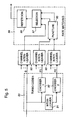
encoders 22. One preferred form of encoding is so-called turbo (parallel concatenated convolutional) coding, in which the encoded data bits comprise the input data bits themselves, referred to as systematic data bits S, and parity bits P1 and P2 provided by convolutional coders operating on the input data bits and on interleaved input data bits. The parity bits P1 and P2 are typically punctured within the turbo coder to provide a desired rate turbo coder. Forencoders 22 constituted by turbo coders, it is necessary to ensure that the subsequentrate matching function 26 does not puncture any of the systematic bits S, but only the parity bits P1 and/or P2. In the case of repetition, it has been determined that repetition of the parity bits P1 and P2 by a factor of the order of 2 or 3 times the repetition of the systematic bits S provides a performance gain. - To these ends, Fig. 5 illustrates a modification of part of the arrangement of Fig. 1 for channel interleaving and rate matching of data encoded by turbo coding. Referring to Fig. 5, a turbo coder constituting one of the
FEC encoders 22 is shown within a dashedline box 90 and, as is well known, comprises aturbo code interleaver 91 which interleaves input data bits, and twoconvolutional coders 92 which operate on the input data bits before and after interleaving to produce parity bits P1 and P2, the input data bits also being supplied to the coder outputs as systematic bits S. A puncturing block, not shown, may also be present to select only some of the parity bits P1 and P2 for supply to the coder outputs. - Instead of a single channel interleaver as described above, Fig. 5 illustrates that
individual channel interleavers 93 are provided for the systematic bit stream and the parity bit stream. As shown in Fig. 5, there are threechannel interleavers 93, but it can be appreciated that the streams of parity bits P1 and P2 can be combined and interleaved together, so that only two channel interleavers are provided, one for the systematic bit stream and the other for the parity bit stream. Further inputs to thechannel interleavers 93 in Fig. 5 indicate the multiplexing of systematic and parity bit streams, respectively, for multiple channels, corresponding to themultiplexer 24 in Fig. 1. - The rate matching function, which follows the
channel interleavers 93, is shown within a dashedline box 94. A puncturingfunction 95 is applied only to the channel-interleaved parity bit streams, whereas arepetition function 96 can be provided to the parity and systematic bit streams, aselector 97 being illustrated to couple the channel-interleaved bits accordingly. The puncturing and repetition can be as described above. It can be appreciated that the illustration in Fig. 5 in this respect is intended diagrammatically to represent the principle that puncturing is not applied to the systematic bits, rather than showing an actual implementation of the rate matching function. It can be appreciated, for example, that puncturing or repetition, as required, could be applied only to the parity bit streams to provide the desired rate matching, without any puncturing or repetition of the systematic bit stream. - Although the above description refers to separate functions and units for the various processes described herein, it can be appreciated that these can in many cases be implemented using functions of one or more digital signal processors or other integrated circuits.
- Although particular embodiments and examples of the invention have been described above, it can be appreciated that numerous modifications, variations, and adaptations may be made without departing from the scope of the invention as defined in the claims.
Claims (13)
- A method of matching a rate of data bits, in a matrix of data bits interleaved by a predetermined interleaving process (53), to a desired rate by deletion of redundant data bits or repetition of data bits derived from the matrix, characterized by the steps of:determining (70) in a non-interleaved matrix of said data bits a pattern of bits to be deleted or repeated to provide said desired data rate;decoding (72) an address of each bit in said pattern in a manner inverse to the interleaving process to produce a respective address of the bit in the matrix of interleaved data bits; anddeleting or repeating (75) the respective bit in the interleaved data bits in dependence upon the respective address.
- A method as claimed in claim 1 wherein the address decoding is performed in the same manner as a coding of addresses for producing the interleaved data bits from the non-interleaved matrix of said data bits.
- A method as claimed in claim 1 or 2 wherein the pattern of bits to be deleted or repeated is dependent upon the number of bits to be deleted or repeated and a column index of the matrix.
- A method as claimed in claim 1, 2, or 3 wherein the interleaving process comprises permuting rows and columns of a matrix of Nr rows and Nc columns, in which data bits to be interleaved are represented row by row, in accordance with:
Row Permutation Ir(k)=[αrk+fc(l)]modNr Column Permutation Ic(l)=[αcl+fr(k)]modNc - A method as claimed in claim 4 wherein fc(l)=ml+[Nr+1]mod2, where m is an integer.
- A method as claimed in claim 5 wherein m is approximately equal to Nr/Nc.
- A method as claimed in claim 4, 5 or 6 wherein fr(k)=2k+[Nc+1]mod2.
- A method as claimed in any of claims 4 to 7 wherein αr is the largest prime number less than Nr/log2(log2(Nr)).
- Rate matching apparatus arranged for carrying out a method as claimed any of claims 1 to 8.
- A method of interleaving data bits comprising permuting rows and columns of a matrix of Nr rows and Nc columns, in which data bits to be interleaved are represented row by row, in accordance with:
Row Permutation Ir(k)=[αrk+fc(l)]modNr Column Permutation Ic(l)=[αcl+fr(k)]modNc - A method as claimed in claim 10 wherein m is approximately equal to Nr/Nc.
- A method as claimed in claim 10 or 11 wherein αr is the largest prime number less than Nr/log2(log2(Nr)).
- A data interleaver arranged for carrying out the method of claim 10, 11, or 12.
Applications Claiming Priority (3)
| Application Number | Priority Date | Filing Date | Title |
|---|---|---|---|
| CA2268853A CA2268853C (en) | 1999-04-13 | 1999-04-13 | Rate matching and channel interleaving for a communications system |
| CA2268853 | 1999-04-13 | ||
| EP00303056A EP1045521B1 (en) | 1999-04-13 | 2000-04-11 | Rate matching and channel interleaving for a communications system |
Related Parent Applications (1)
| Application Number | Title | Priority Date | Filing Date |
|---|---|---|---|
| EP00303056A Division EP1045521B1 (en) | 1999-04-13 | 2000-04-11 | Rate matching and channel interleaving for a communications system |
Publications (3)
| Publication Number | Publication Date |
|---|---|
| EP1538757A2 true EP1538757A2 (en) | 2005-06-08 |
| EP1538757A3 EP1538757A3 (en) | 2006-04-12 |
| EP1538757B1 EP1538757B1 (en) | 2007-12-12 |
Family
ID=4163460
Family Applications (2)
| Application Number | Title | Priority Date | Filing Date |
|---|---|---|---|
| EP05290324A Expired - Lifetime EP1538757B1 (en) | 1999-04-13 | 2000-04-11 | Rate matching and channel interleaving for a communications system |
| EP00303056A Expired - Lifetime EP1045521B1 (en) | 1999-04-13 | 2000-04-11 | Rate matching and channel interleaving for a communications system |
Family Applications After (1)
| Application Number | Title | Priority Date | Filing Date |
|---|---|---|---|
| EP00303056A Expired - Lifetime EP1045521B1 (en) | 1999-04-13 | 2000-04-11 | Rate matching and channel interleaving for a communications system |
Country Status (9)
| Country | Link |
|---|---|
| US (3) | US6744744B1 (en) |
| EP (2) | EP1538757B1 (en) |
| JP (3) | JP4790103B2 (en) |
| CN (3) | CN1327640C (en) |
| AT (2) | ATE381152T1 (en) |
| CA (2) | CA2268853C (en) |
| DE (2) | DE60037463T2 (en) |
| ES (1) | ES2243203T3 (en) |
| HK (1) | HK1032693A1 (en) |
Cited By (1)
| Publication number | Priority date | Publication date | Assignee | Title |
|---|---|---|---|---|
| RU2679732C1 (en) * | 2014-02-20 | 2019-02-12 | Хуавей Текнолоджиз Ко., Лтд. | Method and device for matching transmission rate |
Families Citing this family (93)
| Publication number | Priority date | Publication date | Assignee | Title |
|---|---|---|---|---|
| CA2268853C (en) * | 1999-04-13 | 2011-08-02 | Wen Tong | Rate matching and channel interleaving for a communications system |
| FR2792788B1 (en) | 1999-04-21 | 2001-07-13 | Mitsubishi Electric France | METHOD FOR BALANCING THE Eb / I RATIO IN A CDMA MULTIPLEXING SERVICE SYSTEM AND TELECOMMUNICATION SYSTEM USING THE SAME |
| PL202727B1 (en) * | 1999-06-25 | 2009-07-31 | Samsung Electronics Co Ltd | Apparatus and method for channel coding and multiplexing in cdma communication system |
| IL141800A0 (en) * | 1999-07-06 | 2002-03-10 | Samsung Electronics Co Ltd | Rate matching device and method for a data communication system |
| ID27977A (en) * | 1999-07-08 | 2001-05-03 | Samsung Electronics Co Ltd | APARATUS AND METHODS TO CONTROL DEMULTIPLEXORS AND MULTIPLEXORS USED FOR ADJUSTMENT OF SPEED IN MOVING COMMUNICATION SYSTEMS |
| EP1091517A1 (en) | 1999-10-07 | 2001-04-11 | Siemens Aktiengesellschaft | Communication method and apparatus using punctured or repeated data |
| FI114766B (en) | 1999-11-30 | 2004-12-15 | Nokia Corp | Method and system for implementing interleaving within the frame |
| AU2335001A (en) | 1999-12-20 | 2001-07-03 | Research In Motion Limited | Hybrid automatic repeat request system and method |
| JP2001285077A (en) * | 2000-03-31 | 2001-10-12 | Mitsubishi Electric Corp | Device and method for communication |
| JP4409048B2 (en) * | 2000-05-22 | 2010-02-03 | 三菱電機株式会社 | Communication apparatus and communication method |
| KR100421164B1 (en) * | 2000-06-12 | 2004-03-04 | 삼성전자주식회사 | Apparatus and method for encoding and decoding tfci in a mobile communication system |
| EP2293452B1 (en) * | 2000-07-05 | 2012-06-06 | LG ELectronics INC. | Method of puncturing a turbo coded data block |
| US7242726B2 (en) * | 2000-09-12 | 2007-07-10 | Broadcom Corporation | Parallel concatenated code with soft-in soft-out interactive turbo decoder |
| AU767790B2 (en) * | 2000-10-09 | 2003-11-27 | Samsung Electronics Co., Ltd. | Apparatus and method for coding/decoding TFCI bits in an asynchronous CDMA communication system |
| KR20020033518A (en) * | 2000-10-19 | 2002-05-07 | 윤종용 | Apparatus and method for transmitting of different quality of service data in mobile communication system |
| EP1199834B1 (en) * | 2000-10-21 | 2011-12-21 | Samsung Electronics Co., Ltd. | Method and device for transmitting packet data in mobile communication system |
| US6940867B1 (en) * | 2000-11-02 | 2005-09-06 | Uniden America Corporation | System and method for transmission of digitized audio samples |
| US6798826B1 (en) * | 2000-11-06 | 2004-09-28 | Qualcomm Incorporated | Method and apparatus for performing reverse rate matching in a CDMA system |
| KR100403085B1 (en) * | 2000-12-29 | 2003-10-30 | 엘지전자 주식회사 | Ratematching algorithm for hybrid automatic repeat request system |
| EP1261161A4 (en) * | 2001-01-31 | 2007-11-21 | Mitsubishi Electric Corp | Error correcting communication method and communication apparatus to which this communication method is applied |
| KR100735383B1 (en) * | 2001-02-09 | 2007-07-04 | 삼성전자주식회사 | Data service apparatus and method in wireless system |
| AU2002233774B2 (en) * | 2001-02-13 | 2004-09-02 | Qualcomm Incorporated | Method for Generating Codes in Communication System |
| KR100724921B1 (en) * | 2001-02-16 | 2007-06-04 | 삼성전자주식회사 | Code generating and decoding apparatus and method in communication system |
| TWI283117B (en) | 2001-04-16 | 2007-06-21 | Interdigital Tech Corp | A device for rate matching bits in a code division multiple access wireless communication system |
| US6987778B2 (en) | 2001-05-22 | 2006-01-17 | Qualcomm Incorporated | Enhanced channel interleaving for optimized data throughput |
| US7012911B2 (en) * | 2001-05-31 | 2006-03-14 | Qualcomm Inc. | Method and apparatus for W-CDMA modulation |
| KR100414067B1 (en) * | 2001-06-05 | 2004-01-07 | 엘지전자 주식회사 | Interleave memory control apparatus and method |
| CA2390096C (en) * | 2001-06-11 | 2007-12-18 | Stewart N. Crozier | High-performance low-memory interleaver banks for turbo-codes |
| US7349691B2 (en) * | 2001-07-03 | 2008-03-25 | Microsoft Corporation | System and apparatus for performing broadcast and localcast communications |
| CA2354285A1 (en) * | 2001-07-27 | 2003-01-27 | Ramesh Mantha | Method, system and apparatus for transmitting interleaved data between stations |
| US7260770B2 (en) * | 2001-10-22 | 2007-08-21 | Motorola, Inc. | Block puncturing for turbo code based incremental redundancy |
| KR100445899B1 (en) * | 2001-12-14 | 2004-08-25 | 한국전자통신연구원 | A turbo code encoder and a code rate decreasing method thereof |
| DE50213655D1 (en) * | 2002-01-07 | 2009-08-13 | Siemens Ag | METHOD AND DEVICE FOR DATA TRANSMISSION, WOND RECEIVER IS SIGNALED |
| JP3629241B2 (en) * | 2002-01-30 | 2005-03-16 | 松下電器産業株式会社 | Rate matching device and rate matching method |
| DE10207146A1 (en) * | 2002-02-20 | 2003-08-28 | Infineon Technologies Ag | Hardware circuit for puncturing and repetition coding of data trains |
| BRPI0318842B1 (en) * | 2002-04-08 | 2017-01-17 | Siemens Ag | process for equalizing the data rate on a communication device and communication device |
| US7236480B2 (en) * | 2002-06-07 | 2007-06-26 | Sandbridge Technologies, Inc. | Method of first interleaving of a two interleaver transmitter |
| DE10226394B4 (en) * | 2002-06-13 | 2006-10-19 | Siemens Ag | Method for data transmission |
| US7003703B2 (en) * | 2002-06-21 | 2006-02-21 | Sandbridge Technologies, Inc. | Method of interleaving/deinterleaving in a communication system |
| JP2005535210A (en) * | 2002-08-01 | 2005-11-17 | コーニンクレッカ フィリップス エレクトロニクス エヌ ヴィ | Coding and decoding for rate matching in data transmission |
| JP2004104347A (en) * | 2002-09-06 | 2004-04-02 | Ricoh Co Ltd | Image processing apparatus, image processing method, program, and recording medium |
| US7293217B2 (en) * | 2002-12-16 | 2007-11-06 | Interdigital Technology Corporation | Detection, avoidance and/or correction of problematic puncturing patterns in parity bit streams used when implementing turbo codes |
| US7606157B2 (en) * | 2003-01-23 | 2009-10-20 | Broadcom Corporation | Apparatus and method for communicating arbitrarily encoded data over a 1-gigabit ethernet |
| US7269783B2 (en) * | 2003-04-30 | 2007-09-11 | Lucent Technologies Inc. | Method and apparatus for dedicated hardware and software split implementation of rate matching and de-matching |
| US8576820B2 (en) | 2003-07-03 | 2013-11-05 | Broadcom Corporation | Standby mode for use in a device having a multiple channel physical layer |
| JP4318980B2 (en) * | 2003-07-17 | 2009-08-26 | 三菱電機株式会社 | Encoding processing device and decoding processing device of radio communication device |
| US7145891B2 (en) * | 2003-07-29 | 2006-12-05 | Motorola, Inc. | Method and apparatus to provide desired quality-of-service levels to multiple communication services |
| KR20050020526A (en) * | 2003-08-23 | 2005-03-04 | 삼성전자주식회사 | Apparatus and method for bit interleaving in mobile communication system |
| JP4041450B2 (en) * | 2003-10-23 | 2008-01-30 | ソニー・エリクソン・モバイルコミュニケーションズ株式会社 | Communication terminal device and communication method |
| KR100557087B1 (en) * | 2003-11-18 | 2006-03-03 | 삼성전자주식회사 | Apparatus for bit de-collection using high speed downlink packet access scheme and method thereof |
| US7558280B2 (en) * | 2003-12-11 | 2009-07-07 | Broadcom Corporation | Apparatus and method for auto-negotiation in a communication system |
| US7414971B2 (en) * | 2004-09-03 | 2008-08-19 | Analog Devices, Inc. | Method and apparatus for rate matching in a telecommunications system |
| US20060156171A1 (en) * | 2004-12-15 | 2006-07-13 | Seagate Technology Llc | Combining spectral shaping with turbo coding in a channel coding system |
| FR2880483A1 (en) * | 2004-12-31 | 2006-07-07 | France Telecom | INTERLACING METHOD AND DEVICE |
| US7685495B2 (en) * | 2005-05-12 | 2010-03-23 | Qualcomm Incorporated | Apparatus and method for channel interleaving in communications system |
| WO2007043384A1 (en) * | 2005-10-11 | 2007-04-19 | Matsushita Electric Industrial Co., Ltd. | Encoding method, encoding apparatus, decoding method and decoding apparatus |
| US20070115960A1 (en) * | 2005-11-04 | 2007-05-24 | Mediatek Inc. | De-interleaver for data decoding |
| US20070104225A1 (en) * | 2005-11-10 | 2007-05-10 | Mitsubishi Denki Kabushiki Kaisha | Communication apparatus, transmitter, receiver, and error correction optical communication system |
| US7590044B2 (en) * | 2005-11-14 | 2009-09-15 | Motorola, Inc. | Method and apparatus for interleaving\within a communication system |
| US7742519B2 (en) * | 2005-12-19 | 2010-06-22 | St-Ericsson Sa | Method for rate matching in data transmission |
| EP1968225A1 (en) | 2005-12-27 | 2008-09-10 | Matsushita Electric Industrial Co., Ltd. | Radio transmitting apparatus and multicarrier signal generating method |
| CN101039245A (en) * | 2006-03-13 | 2007-09-19 | 华为技术有限公司 | Data transmission method from high speed Ethernet to optical transmission network and related interface and equipment |
| US20080120530A1 (en) * | 2006-11-22 | 2008-05-22 | Yu-Min Chuang | Transceiver puncture circuit of wireless communication system |
| US8726121B2 (en) * | 2007-03-27 | 2014-05-13 | Qualcomm Incorporated | Circular buffer based rate matching |
| WO2008151061A1 (en) * | 2007-05-31 | 2008-12-11 | Interdigital Technology Corporation | Channel coding and rate matching for lte control channels |
| US8266508B2 (en) * | 2007-06-08 | 2012-09-11 | Telefonaktiebolaget L M Ericsson (Publ) | Computational efficient convolutional coding with rate matching |
| CN101087181B (en) * | 2007-07-11 | 2011-09-21 | 中兴通讯股份有限公司 | A method for removing interweaving and speed match |
| JP5088110B2 (en) * | 2007-11-27 | 2012-12-05 | 日本電気株式会社 | Receiver circuit |
| CN101674150B (en) * | 2008-09-12 | 2013-06-12 | 中兴通讯股份有限公司 | Rate matching method and device |
| US8621322B2 (en) * | 2008-09-30 | 2013-12-31 | Freescale Semiconductor, Inc. | Data interleaver |
| CN101710850B (en) * | 2008-12-26 | 2013-10-30 | 三星电子株式会社 | Convolution Turbo encoding method and device for realizing encoding method |
| CN101540654B (en) * | 2009-05-04 | 2011-07-27 | 普天信息技术研究院有限公司 | Method for interlacing rate matching and de-interlacing off-rate matching |
| CN101547064B (en) * | 2009-05-06 | 2011-11-09 | 普天信息技术研究院有限公司 | Interleaving and rate matching and de-interleaving and rate de-matching methods |
| JP5365455B2 (en) * | 2009-09-30 | 2013-12-11 | 富士通株式会社 | RATE ADJUSTMENT DEVICE, RATE ADJUSTMENT METHOD, AND RATE ADJUSTMENT PROGRAM |
| CN101783719B (en) * | 2010-03-18 | 2013-03-20 | 华为技术有限公司 | Rate matching and rate de-matching method, device and communication system |
| KR20120071511A (en) * | 2010-12-23 | 2012-07-03 | 한국전자통신연구원 | Method and apparatus for data rate matching for mobile communication systems |
| US8532112B2 (en) * | 2011-09-23 | 2013-09-10 | Lsi Corporation | Interleaving for wideband code division multiple access |
| EP3062452B1 (en) * | 2013-10-22 | 2019-12-04 | LG Electronics Inc. | Method and apparatus for transmitting physical downlink control channel in wireless access system supporting machine-type communication |
| EP3073660B1 (en) | 2013-11-20 | 2020-06-24 | Huawei Technologies Co., Ltd. | Polar code processing method and device |
| WO2015089741A1 (en) | 2013-12-17 | 2015-06-25 | 华为技术有限公司 | Data reception method and device, and data sending method and device |
| KR101844438B1 (en) | 2014-02-21 | 2018-04-02 | 후아웨이 테크놀러지 컴퍼니 리미티드 | Method and apparatus for rate matching of polar code |
| CA2971769C (en) * | 2014-12-22 | 2021-07-06 | Huawei Technologies Co., Ltd. | Polar code encoding method and encoding apparatus |
| KR102422275B1 (en) * | 2015-07-30 | 2022-07-18 | 삼성전자주식회사 | A method and apparatus for channel encoding and decoding in a wireless communication system |
| JP6820168B2 (en) * | 2016-08-29 | 2021-01-27 | 日本放送協会 | Transmitter and receiver |
| US10429491B2 (en) | 2016-09-12 | 2019-10-01 | The Boeing Company | Systems and methods for pulse descriptor word generation using blind source separation |
| US9954561B2 (en) | 2016-09-12 | 2018-04-24 | The Boeing Company | Systems and methods for parallelizing and pipelining a tunable blind source separation filter |
| US10324168B2 (en) | 2016-09-12 | 2019-06-18 | The Boeing Company | Systems and methods for spatial filtering using data with widely different error magnitudes |
| US10324167B2 (en) | 2016-09-12 | 2019-06-18 | The Boeing Company | Systems and methods for adding functional grid elements to stochastic sparse tree grids for spatial filtering |
| US10499416B2 (en) * | 2017-01-10 | 2019-12-03 | Qualcomm Incorporated | Downlink channel rate matching of synchronization signal block transmissions in a new radio wireless communication system |
| WO2018129695A1 (en) * | 2017-01-12 | 2018-07-19 | Qualcomm Incorporated | Puncturing and repetition for data encoding |
| US11258535B2 (en) * | 2017-06-16 | 2022-02-22 | Lg Electronics Inc. | Method and apparatus for transmitting information |
| US20200403640A1 (en) * | 2018-01-12 | 2020-12-24 | Lg Electronics Inc. | Method for performing interleaving and interleaver |
| CN112104380B (en) * | 2020-09-21 | 2024-03-19 | Oppo广东移动通信有限公司 | Rate matching method, chip and terminal |
Citations (6)
| Publication number | Priority date | Publication date | Assignee | Title |
|---|---|---|---|---|
| US5418813A (en) * | 1993-12-06 | 1995-05-23 | Motorola, Inc. | Method and apparatus for creating a composite waveform |
| US5675726A (en) * | 1992-03-12 | 1997-10-07 | Emc Corporation | Flexible parity generation circuit |
| US5838733A (en) * | 1993-12-23 | 1998-11-17 | Motorola, Inc. | Method and apparatus for mitigating signal distortion in a communication system |
| EP0881795A2 (en) * | 1997-05-29 | 1998-12-02 | TRW Inc. | Communication system for broadcasting to mobile users |
| EP1045522A1 (en) * | 1999-04-07 | 2000-10-18 | Mitsubishi Electric Telecom Europe | Method and device for channel interleaving and multiplexing |
| US20040146029A1 (en) * | 1999-04-13 | 2004-07-29 | Wen Tong | Rate matching and channel interleaving for a communications system |
Family Cites Families (20)
| Publication number | Priority date | Publication date | Assignee | Title |
|---|---|---|---|---|
| JP3169522B2 (en) * | 1995-01-19 | 2001-05-28 | 沖電気工業株式会社 | Data receiving device |
| JPH08298466A (en) * | 1995-04-27 | 1996-11-12 | N T T Ido Tsushinmo Kk | Method for generating error correction code |
| WO1997033402A1 (en) * | 1996-03-04 | 1997-09-12 | Ericsson Inc. | Digital communication system for adapting communications protocol based on a current communication channel condition |
| EP0849891A3 (en) * | 1996-12-20 | 2000-01-19 | Siemens Aktiengesellschaft | Method and apparatus for establishing a traffic channel in a mobile radio network |
| JPH10276100A (en) * | 1997-03-28 | 1998-10-13 | Hitachi Denshi Ltd | Error correction system in digital communication |
| US5852614A (en) * | 1997-05-29 | 1998-12-22 | Trw Inc. | Weighted interleaving for correlated channel coding |
| KR19990003242A (en) * | 1997-06-25 | 1999-01-15 | 윤종용 | Structural Punched Convolutional Codes and Decoders |
| WO1999007076A2 (en) * | 1997-07-30 | 1999-02-11 | Samsung Electronics Co., Ltd. | Adaptive channel encoding method and device |
| US6088387A (en) * | 1997-12-31 | 2000-07-11 | At&T Corp. | Multi-channel parallel/serial concatenated convolutional codes and trellis coded modulation encoder/decoder |
| US6430722B1 (en) * | 1998-01-23 | 2002-08-06 | Hughes Electronics Corporation | Forward error correction scheme for data channels using universal turbo codes |
| US6370669B1 (en) * | 1998-01-23 | 2002-04-09 | Hughes Electronics Corporation | Sets of rate-compatible universal turbo codes nearly optimized over various rates and interleaver sizes |
| US6101626A (en) * | 1998-02-04 | 2000-08-08 | Lsi Logic Corporation | Method for choosing coding schemes, mappings, and puncturing rates for modulations/encoding systems |
| US6147964A (en) * | 1998-05-07 | 2000-11-14 | Qualcomm Inc. | Method and apparatus for performing rate determination using orthogonal rate-dependent walsh covering codes |
| EP1027772A1 (en) * | 1998-06-05 | 2000-08-16 | Samsung Electronics Co., Ltd. | Channel coding device and method for rate matching |
| GB9814960D0 (en) | 1998-07-10 | 1998-09-09 | Koninkl Philips Electronics Nv | Coding device and communication system using the same |
| US6028897A (en) * | 1998-10-22 | 2000-02-22 | The Aerospace Corporation | Error-floor mitigating turbo code communication method |
| US6304991B1 (en) * | 1998-12-04 | 2001-10-16 | Qualcomm Incorporated | Turbo code interleaver using linear congruential sequence |
| JP3515036B2 (en) * | 1999-02-19 | 2004-04-05 | 株式会社エヌ・ティ・ティ・ドコモ | Interleaving method, interleaving device, turbo coding method, and turbo coding device |
| CN1175582C (en) * | 1999-03-19 | 2004-11-10 | 西门子公司 | Data transmission with interleaving and subsequent rate matching by puncturing or repetition |
| AU2002233774B2 (en) * | 2001-02-13 | 2004-09-02 | Qualcomm Incorporated | Method for Generating Codes in Communication System |
-
1999
- 1999-04-13 CA CA2268853A patent/CA2268853C/en not_active Expired - Lifetime
- 1999-04-13 CA CA2742096A patent/CA2742096C/en not_active Expired - Lifetime
-
2000
- 2000-04-07 US US09/544,981 patent/US6744744B1/en not_active Expired - Lifetime
- 2000-04-11 DE DE60037463T patent/DE60037463T2/en not_active Expired - Lifetime
- 2000-04-11 ES ES00303056T patent/ES2243203T3/en not_active Expired - Lifetime
- 2000-04-11 JP JP2000109059A patent/JP4790103B2/en not_active Expired - Lifetime
- 2000-04-11 AT AT05290324T patent/ATE381152T1/en not_active IP Right Cessation
- 2000-04-11 DE DE60020637T patent/DE60020637T2/en not_active Expired - Lifetime
- 2000-04-11 AT AT00303056T patent/ATE297610T1/en not_active IP Right Cessation
- 2000-04-11 EP EP05290324A patent/EP1538757B1/en not_active Expired - Lifetime
- 2000-04-11 EP EP00303056A patent/EP1045521B1/en not_active Expired - Lifetime
- 2000-04-12 CN CNB2004100620072A patent/CN1327640C/en not_active Expired - Lifetime
- 2000-04-12 CN CNB2004100620087A patent/CN100344080C/en not_active Expired - Lifetime
- 2000-04-12 CN CNB001067117A patent/CN1187903C/en not_active Expired - Lifetime
-
2001
- 2001-05-04 HK HK01103173A patent/HK1032693A1/en not_active IP Right Cessation
-
2004
- 2004-01-08 US US10/753,546 patent/US20040146029A1/en not_active Abandoned
-
2011
- 2011-01-12 JP JP2011004079A patent/JP5199403B2/en not_active Expired - Lifetime
-
2012
- 2012-11-21 US US13/683,011 patent/US20130318416A1/en not_active Abandoned
- 2012-12-05 JP JP2012266373A patent/JP5457535B2/en not_active Expired - Lifetime
Patent Citations (7)
| Publication number | Priority date | Publication date | Assignee | Title |
|---|---|---|---|---|
| US5675726A (en) * | 1992-03-12 | 1997-10-07 | Emc Corporation | Flexible parity generation circuit |
| US5418813A (en) * | 1993-12-06 | 1995-05-23 | Motorola, Inc. | Method and apparatus for creating a composite waveform |
| US5838733A (en) * | 1993-12-23 | 1998-11-17 | Motorola, Inc. | Method and apparatus for mitigating signal distortion in a communication system |
| EP0881795A2 (en) * | 1997-05-29 | 1998-12-02 | TRW Inc. | Communication system for broadcasting to mobile users |
| US6304609B1 (en) * | 1997-05-29 | 2001-10-16 | Trw Inc. | Communication system for broadcasting to mobile users |
| EP1045522A1 (en) * | 1999-04-07 | 2000-10-18 | Mitsubishi Electric Telecom Europe | Method and device for channel interleaving and multiplexing |
| US20040146029A1 (en) * | 1999-04-13 | 2004-07-29 | Wen Tong | Rate matching and channel interleaving for a communications system |
Non-Patent Citations (1)
| Title |
|---|
| UMTS: "UTRAN; UTRA FDD, multiplexing, channel coding and interleaving description (UMTS XX.04 version 1.0.0)" ETSI, February 1999 (1999-02), XP002181831 * |
Cited By (1)
| Publication number | Priority date | Publication date | Assignee | Title |
|---|---|---|---|---|
| RU2679732C1 (en) * | 2014-02-20 | 2019-02-12 | Хуавей Текнолоджиз Ко., Лтд. | Method and device for matching transmission rate |
Also Published As
| Publication number | Publication date |
|---|---|
| JP4790103B2 (en) | 2011-10-12 |
| CA2742096A1 (en) | 2000-10-13 |
| US6744744B1 (en) | 2004-06-01 |
| EP1045521A3 (en) | 2003-01-02 |
| EP1538757B1 (en) | 2007-12-12 |
| CN100344080C (en) | 2007-10-17 |
| ES2243203T3 (en) | 2005-12-01 |
| DE60037463D1 (en) | 2008-01-24 |
| JP2013048492A (en) | 2013-03-07 |
| CN1564485A (en) | 2005-01-12 |
| DE60020637D1 (en) | 2005-07-14 |
| JP5199403B2 (en) | 2013-05-15 |
| CN1272733A (en) | 2000-11-08 |
| JP2001057521A (en) | 2001-02-27 |
| DE60020637T2 (en) | 2006-05-04 |
| CA2742096C (en) | 2015-01-06 |
| CN1187903C (en) | 2005-02-02 |
| CA2268853A1 (en) | 2000-10-13 |
| ATE381152T1 (en) | 2007-12-15 |
| EP1045521B1 (en) | 2005-06-08 |
| EP1538757A3 (en) | 2006-04-12 |
| US20040146029A1 (en) | 2004-07-29 |
| JP2011139475A (en) | 2011-07-14 |
| JP5457535B2 (en) | 2014-04-02 |
| ATE297610T1 (en) | 2005-06-15 |
| EP1045521A2 (en) | 2000-10-18 |
| DE60037463T2 (en) | 2008-12-04 |
| US20130318416A1 (en) | 2013-11-28 |
| CN1564484A (en) | 2005-01-12 |
| CN1327640C (en) | 2007-07-18 |
| HK1032693A1 (en) | 2001-07-27 |
| CA2268853C (en) | 2011-08-02 |
Similar Documents
| Publication | Publication Date | Title |
|---|---|---|
| EP1045521B1 (en) | Rate matching and channel interleaving for a communications system | |
| US6684361B2 (en) | Data interleaver and method of interleaving data | |
| US8543884B2 (en) | Communications channel parallel interleaver and de-interleaver | |
| JP3996514B2 (en) | Buffer architecture for turbo decoder | |
| CA2689587C (en) | An apparatus comprising a circular buffer and method for assigning redundancy versions to a circular buffer | |
| EP1601109B1 (en) | Adaptive channel encoding method and device | |
| US6289486B1 (en) | Adaptive channel encoding method and device | |
| US7814388B2 (en) | System and method for interleaving data in a wireless transmitter | |
| KR20020067382A (en) | Code generating and decoding apparatus and method in communication system | |
| CA2366592A1 (en) | A system and method employing a modular decoder for decoding turbo and turbo-like codes in a communications network | |
| US6543013B1 (en) | Intra-row permutation for turbo code | |
| US8065593B2 (en) | Erasures assisted block code decoder and related method | |
| US20070220377A1 (en) | Interleaving apparatus and method in communication system | |
| EP1537673B1 (en) | Method of interleaving/deinterleaving in a communication system | |
| KR20010080130A (en) | Hybrid interleaver for turbo codes |
Legal Events
| Date | Code | Title | Description |
|---|---|---|---|
| PUAI | Public reference made under article 153(3) epc to a published international application that has entered the european phase |
Free format text: ORIGINAL CODE: 0009012 |
|
| 17P | Request for examination filed |
Effective date: 20050222 |
|
| AC | Divisional application: reference to earlier application |
Ref document number: 1045521 Country of ref document: EP Kind code of ref document: P |
|
| AK | Designated contracting states |
Kind code of ref document: A2 Designated state(s): AT BE CH CY DE DK ES FI FR GB GR IE IT LI LU MC NL PT SE |
|
| PUAL | Search report despatched |
Free format text: ORIGINAL CODE: 0009013 |
|
| AK | Designated contracting states |
Kind code of ref document: A3 Designated state(s): AT BE CH CY DE DK ES FI FR GB GR IE IT LI LU MC NL PT SE |
|
| RIC1 | Information provided on ipc code assigned before grant |
Ipc: H04L 1/00 20060101ALI20060223BHEP Ipc: H03M 13/00 20060101AFI20050415BHEP Ipc: H03M 13/29 20060101ALI20060223BHEP Ipc: H03M 13/27 20060101ALI20060223BHEP |
|
| AKX | Designation fees paid |
Designated state(s): AT BE CH CY DE DK ES FI FR GB GR IE IT LI LU MC NL PT SE |
|
| 17Q | First examination report despatched |
Effective date: 20070117 |
|
| GRAP | Despatch of communication of intention to grant a patent |
Free format text: ORIGINAL CODE: EPIDOSNIGR1 |
|
| GRAS | Grant fee paid |
Free format text: ORIGINAL CODE: EPIDOSNIGR3 |
|
| GRAA | (expected) grant |
Free format text: ORIGINAL CODE: 0009210 |
|
| AC | Divisional application: reference to earlier application |
Ref document number: 1045521 Country of ref document: EP Kind code of ref document: P |
|
| AK | Designated contracting states |
Kind code of ref document: B1 Designated state(s): AT BE CH CY DE DK ES FI FR GB GR IE IT LI LU MC NL PT SE |
|
| REG | Reference to a national code |
Ref country code: GB Ref legal event code: FG4D |
|
| REG | Reference to a national code |
Ref country code: CH Ref legal event code: EP |
|
| REG | Reference to a national code |
Ref country code: IE Ref legal event code: FG4D |
|
| REF | Corresponds to: |
Ref document number: 60037463 Country of ref document: DE Date of ref document: 20080124 Kind code of ref document: P |
|
| PG25 | Lapsed in a contracting state [announced via postgrant information from national office to epo] |
Ref country code: LI Free format text: LAPSE BECAUSE OF FAILURE TO SUBMIT A TRANSLATION OF THE DESCRIPTION OR TO PAY THE FEE WITHIN THE PRESCRIBED TIME-LIMIT Effective date: 20071212 Ref country code: SE Free format text: LAPSE BECAUSE OF FAILURE TO SUBMIT A TRANSLATION OF THE DESCRIPTION OR TO PAY THE FEE WITHIN THE PRESCRIBED TIME-LIMIT Effective date: 20080312 Ref country code: CH Free format text: LAPSE BECAUSE OF FAILURE TO SUBMIT A TRANSLATION OF THE DESCRIPTION OR TO PAY THE FEE WITHIN THE PRESCRIBED TIME-LIMIT Effective date: 20071212 |
|
| PG25 | Lapsed in a contracting state [announced via postgrant information from national office to epo] |
Ref country code: NL Free format text: LAPSE BECAUSE OF FAILURE TO SUBMIT A TRANSLATION OF THE DESCRIPTION OR TO PAY THE FEE WITHIN THE PRESCRIBED TIME-LIMIT Effective date: 20071212 Ref country code: FI Free format text: LAPSE BECAUSE OF FAILURE TO SUBMIT A TRANSLATION OF THE DESCRIPTION OR TO PAY THE FEE WITHIN THE PRESCRIBED TIME-LIMIT Effective date: 20071212 |
|
| NLV1 | Nl: lapsed or annulled due to failure to fulfill the requirements of art. 29p and 29m of the patents act | ||
| REG | Reference to a national code |
Ref country code: CH Ref legal event code: PL |
|
| PG25 | Lapsed in a contracting state [announced via postgrant information from national office to epo] |
Ref country code: AT Free format text: LAPSE BECAUSE OF FAILURE TO SUBMIT A TRANSLATION OF THE DESCRIPTION OR TO PAY THE FEE WITHIN THE PRESCRIBED TIME-LIMIT Effective date: 20071212 |
|
| PG25 | Lapsed in a contracting state [announced via postgrant information from national office to epo] |
Ref country code: ES Free format text: LAPSE BECAUSE OF FAILURE TO SUBMIT A TRANSLATION OF THE DESCRIPTION OR TO PAY THE FEE WITHIN THE PRESCRIBED TIME-LIMIT Effective date: 20080323 |
|
| ET | Fr: translation filed | ||
| PG25 | Lapsed in a contracting state [announced via postgrant information from national office to epo] |
Ref country code: BE Free format text: LAPSE BECAUSE OF FAILURE TO SUBMIT A TRANSLATION OF THE DESCRIPTION OR TO PAY THE FEE WITHIN THE PRESCRIBED TIME-LIMIT Effective date: 20071212 |
|
| PG25 | Lapsed in a contracting state [announced via postgrant information from national office to epo] |
Ref country code: PT Free format text: LAPSE BECAUSE OF FAILURE TO SUBMIT A TRANSLATION OF THE DESCRIPTION OR TO PAY THE FEE WITHIN THE PRESCRIBED TIME-LIMIT Effective date: 20080512 |
|
| PLBE | No opposition filed within time limit |
Free format text: ORIGINAL CODE: 0009261 |
|
| STAA | Information on the status of an ep patent application or granted ep patent |
Free format text: STATUS: NO OPPOSITION FILED WITHIN TIME LIMIT |
|
| PG25 | Lapsed in a contracting state [announced via postgrant information from national office to epo] |
Ref country code: DK Free format text: LAPSE BECAUSE OF FAILURE TO SUBMIT A TRANSLATION OF THE DESCRIPTION OR TO PAY THE FEE WITHIN THE PRESCRIBED TIME-LIMIT Effective date: 20071212 |
|
| 26N | No opposition filed |
Effective date: 20080915 |
|
| PG25 | Lapsed in a contracting state [announced via postgrant information from national office to epo] |
Ref country code: MC Free format text: LAPSE BECAUSE OF NON-PAYMENT OF DUE FEES Effective date: 20080430 |
|
| PG25 | Lapsed in a contracting state [announced via postgrant information from national office to epo] |
Ref country code: GR Free format text: LAPSE BECAUSE OF FAILURE TO SUBMIT A TRANSLATION OF THE DESCRIPTION OR TO PAY THE FEE WITHIN THE PRESCRIBED TIME-LIMIT Effective date: 20080313 |
|
| PG25 | Lapsed in a contracting state [announced via postgrant information from national office to epo] |
Ref country code: IE Free format text: LAPSE BECAUSE OF NON-PAYMENT OF DUE FEES Effective date: 20080411 |
|
| PG25 | Lapsed in a contracting state [announced via postgrant information from national office to epo] |
Ref country code: CY Free format text: LAPSE BECAUSE OF FAILURE TO SUBMIT A TRANSLATION OF THE DESCRIPTION OR TO PAY THE FEE WITHIN THE PRESCRIBED TIME-LIMIT Effective date: 20071212 |
|
| PG25 | Lapsed in a contracting state [announced via postgrant information from national office to epo] |
Ref country code: LU Free format text: LAPSE BECAUSE OF NON-PAYMENT OF DUE FEES Effective date: 20080411 |
|
| REG | Reference to a national code |
Ref country code: FR Ref legal event code: TP |
|
| REG | Reference to a national code |
Ref country code: GB Ref legal event code: 732E Free format text: REGISTERED BETWEEN 20110113 AND 20110119 |
|
| PG25 | Lapsed in a contracting state [announced via postgrant information from national office to epo] |
Ref country code: IT Free format text: LAPSE BECAUSE OF NON-PAYMENT OF DUE FEES Effective date: 20080430 |
|
| REG | Reference to a national code |
Ref country code: DE Ref legal event code: R081 Ref document number: 60037463 Country of ref document: DE Owner name: ERICSSON AB, SE Free format text: FORMER OWNER: NORTEL NETWORKS LTD., ST. LAURENT, CA Effective date: 20110510 Ref country code: DE Ref legal event code: R081 Ref document number: 60037463 Country of ref document: DE Owner name: ERICSSON AB, SE Free format text: FORMER OWNER: NORTEL NETWORKS LTD., ST. LAURENT, QUEBEC, CA Effective date: 20110510 |
|
| REG | Reference to a national code |
Ref country code: FR Ref legal event code: PLFP Year of fee payment: 16 |
|
| REG | Reference to a national code |
Ref country code: FR Ref legal event code: PLFP Year of fee payment: 17 |
|
| REG | Reference to a national code |
Ref country code: FR Ref legal event code: PLFP Year of fee payment: 18 |
|
| REG | Reference to a national code |
Ref country code: FR Ref legal event code: PLFP Year of fee payment: 19 |
|
| PGFP | Annual fee paid to national office [announced via postgrant information from national office to epo] |
Ref country code: DE Payment date: 20190429 Year of fee payment: 20 |
|
| PGFP | Annual fee paid to national office [announced via postgrant information from national office to epo] |
Ref country code: FR Payment date: 20190425 Year of fee payment: 20 |
|
| PGFP | Annual fee paid to national office [announced via postgrant information from national office to epo] |
Ref country code: GB Payment date: 20190429 Year of fee payment: 20 |
|
| REG | Reference to a national code |
Ref country code: DE Ref legal event code: R071 Ref document number: 60037463 Country of ref document: DE |
|
| REG | Reference to a national code |
Ref country code: GB Ref legal event code: PE20 Expiry date: 20200410 |
|
| PG25 | Lapsed in a contracting state [announced via postgrant information from national office to epo] |
Ref country code: GB Free format text: LAPSE BECAUSE OF EXPIRATION OF PROTECTION Effective date: 20200410 |