EP1541361A2 - Ink cartridge, ink jet recording apparatus, and set of ink cartridges - Google Patents
Ink cartridge, ink jet recording apparatus, and set of ink cartridges Download PDFInfo
- Publication number
- EP1541361A2 EP1541361A2 EP05005631A EP05005631A EP1541361A2 EP 1541361 A2 EP1541361 A2 EP 1541361A2 EP 05005631 A EP05005631 A EP 05005631A EP 05005631 A EP05005631 A EP 05005631A EP 1541361 A2 EP1541361 A2 EP 1541361A2
- Authority
- EP
- European Patent Office
- Prior art keywords
- ink
- ink cartridge
- carriage
- electrode
- container
- Prior art date
- Legal status (The legal status is an assumption and is not a legal conclusion. Google has not performed a legal analysis and makes no representation as to the accuracy of the status listed.)
- Granted
Links
Images


Classifications
-
- B—PERFORMING OPERATIONS; TRANSPORTING
- B41—PRINTING; LINING MACHINES; TYPEWRITERS; STAMPS
- B41J—TYPEWRITERS; SELECTIVE PRINTING MECHANISMS, i.e. MECHANISMS PRINTING OTHERWISE THAN FROM A FORME; CORRECTION OF TYPOGRAPHICAL ERRORS
- B41J2/00—Typewriters or selective printing mechanisms characterised by the printing or marking process for which they are designed
- B41J2/005—Typewriters or selective printing mechanisms characterised by the printing or marking process for which they are designed characterised by bringing liquid or particles selectively into contact with a printing material
- B41J2/01—Ink jet
- B41J2/17—Ink jet characterised by ink handling
- B41J2/175—Ink supply systems ; Circuit parts therefor
- B41J2/17503—Ink cartridges
- B41J2/17526—Electrical contacts to the cartridge
- B41J2/1753—Details of contacts on the cartridge, e.g. protection of contacts
-
- B—PERFORMING OPERATIONS; TRANSPORTING
- B41—PRINTING; LINING MACHINES; TYPEWRITERS; STAMPS
- B41J—TYPEWRITERS; SELECTIVE PRINTING MECHANISMS, i.e. MECHANISMS PRINTING OTHERWISE THAN FROM A FORME; CORRECTION OF TYPOGRAPHICAL ERRORS
- B41J2/00—Typewriters or selective printing mechanisms characterised by the printing or marking process for which they are designed
- B41J2/005—Typewriters or selective printing mechanisms characterised by the printing or marking process for which they are designed characterised by bringing liquid or particles selectively into contact with a printing material
- B41J2/01—Ink jet
- B41J2/17—Ink jet characterised by ink handling
- B41J2/175—Ink supply systems ; Circuit parts therefor
- B41J2/17503—Ink cartridges
- B41J2/17506—Refilling of the cartridge
- B41J2/17509—Whilst mounted in the printer
-
- B—PERFORMING OPERATIONS; TRANSPORTING
- B41—PRINTING; LINING MACHINES; TYPEWRITERS; STAMPS
- B41J—TYPEWRITERS; SELECTIVE PRINTING MECHANISMS, i.e. MECHANISMS PRINTING OTHERWISE THAN FROM A FORME; CORRECTION OF TYPOGRAPHICAL ERRORS
- B41J2/00—Typewriters or selective printing mechanisms characterised by the printing or marking process for which they are designed
- B41J2/005—Typewriters or selective printing mechanisms characterised by the printing or marking process for which they are designed characterised by bringing liquid or particles selectively into contact with a printing material
- B41J2/01—Ink jet
- B41J2/17—Ink jet characterised by ink handling
- B41J2/175—Ink supply systems ; Circuit parts therefor
- B41J2/17503—Ink cartridges
- B41J2/17513—Inner structure
-
- B—PERFORMING OPERATIONS; TRANSPORTING
- B41—PRINTING; LINING MACHINES; TYPEWRITERS; STAMPS
- B41J—TYPEWRITERS; SELECTIVE PRINTING MECHANISMS, i.e. MECHANISMS PRINTING OTHERWISE THAN FROM A FORME; CORRECTION OF TYPOGRAPHICAL ERRORS
- B41J2/00—Typewriters or selective printing mechanisms characterised by the printing or marking process for which they are designed
- B41J2/005—Typewriters or selective printing mechanisms characterised by the printing or marking process for which they are designed characterised by bringing liquid or particles selectively into contact with a printing material
- B41J2/01—Ink jet
- B41J2/17—Ink jet characterised by ink handling
- B41J2/175—Ink supply systems ; Circuit parts therefor
- B41J2/17503—Ink cartridges
- B41J2/1752—Mounting within the printer
-
- B—PERFORMING OPERATIONS; TRANSPORTING
- B41—PRINTING; LINING MACHINES; TYPEWRITERS; STAMPS
- B41J—TYPEWRITERS; SELECTIVE PRINTING MECHANISMS, i.e. MECHANISMS PRINTING OTHERWISE THAN FROM A FORME; CORRECTION OF TYPOGRAPHICAL ERRORS
- B41J2/00—Typewriters or selective printing mechanisms characterised by the printing or marking process for which they are designed
- B41J2/005—Typewriters or selective printing mechanisms characterised by the printing or marking process for which they are designed characterised by bringing liquid or particles selectively into contact with a printing material
- B41J2/01—Ink jet
- B41J2/17—Ink jet characterised by ink handling
- B41J2/175—Ink supply systems ; Circuit parts therefor
- B41J2/17503—Ink cartridges
- B41J2/17526—Electrical contacts to the cartridge
-
- B—PERFORMING OPERATIONS; TRANSPORTING
- B41—PRINTING; LINING MACHINES; TYPEWRITERS; STAMPS
- B41J—TYPEWRITERS; SELECTIVE PRINTING MECHANISMS, i.e. MECHANISMS PRINTING OTHERWISE THAN FROM A FORME; CORRECTION OF TYPOGRAPHICAL ERRORS
- B41J2/00—Typewriters or selective printing mechanisms characterised by the printing or marking process for which they are designed
- B41J2/005—Typewriters or selective printing mechanisms characterised by the printing or marking process for which they are designed characterised by bringing liquid or particles selectively into contact with a printing material
- B41J2/01—Ink jet
- B41J2/17—Ink jet characterised by ink handling
- B41J2/175—Ink supply systems ; Circuit parts therefor
- B41J2/17503—Ink cartridges
- B41J2/17543—Cartridge presence detection or type identification
- B41J2/17546—Cartridge presence detection or type identification electronically
-
- B—PERFORMING OPERATIONS; TRANSPORTING
- B41—PRINTING; LINING MACHINES; TYPEWRITERS; STAMPS
- B41J—TYPEWRITERS; SELECTIVE PRINTING MECHANISMS, i.e. MECHANISMS PRINTING OTHERWISE THAN FROM A FORME; CORRECTION OF TYPOGRAPHICAL ERRORS
- B41J2/00—Typewriters or selective printing mechanisms characterised by the printing or marking process for which they are designed
- B41J2/005—Typewriters or selective printing mechanisms characterised by the printing or marking process for which they are designed characterised by bringing liquid or particles selectively into contact with a printing material
- B41J2/01—Ink jet
- B41J2/17—Ink jet characterised by ink handling
- B41J2/175—Ink supply systems ; Circuit parts therefor
- B41J2/17503—Ink cartridges
- B41J2/17543—Cartridge presence detection or type identification
- B41J2/1755—Cartridge presence detection or type identification mechanically
-
- B—PERFORMING OPERATIONS; TRANSPORTING
- B41—PRINTING; LINING MACHINES; TYPEWRITERS; STAMPS
- B41J—TYPEWRITERS; SELECTIVE PRINTING MECHANISMS, i.e. MECHANISMS PRINTING OTHERWISE THAN FROM A FORME; CORRECTION OF TYPOGRAPHICAL ERRORS
- B41J2/00—Typewriters or selective printing mechanisms characterised by the printing or marking process for which they are designed
- B41J2/005—Typewriters or selective printing mechanisms characterised by the printing or marking process for which they are designed characterised by bringing liquid or particles selectively into contact with a printing material
- B41J2/01—Ink jet
- B41J2/17—Ink jet characterised by ink handling
- B41J2/175—Ink supply systems ; Circuit parts therefor
- B41J2/17503—Ink cartridges
- B41J2/17553—Outer structure
-
- B—PERFORMING OPERATIONS; TRANSPORTING
- B41—PRINTING; LINING MACHINES; TYPEWRITERS; STAMPS
- B41J—TYPEWRITERS; SELECTIVE PRINTING MECHANISMS, i.e. MECHANISMS PRINTING OTHERWISE THAN FROM A FORME; CORRECTION OF TYPOGRAPHICAL ERRORS
- B41J2/00—Typewriters or selective printing mechanisms characterised by the printing or marking process for which they are designed
- B41J2/005—Typewriters or selective printing mechanisms characterised by the printing or marking process for which they are designed characterised by bringing liquid or particles selectively into contact with a printing material
- B41J2/01—Ink jet
- B41J2/17—Ink jet characterised by ink handling
- B41J2/175—Ink supply systems ; Circuit parts therefor
- B41J2/17503—Ink cartridges
- B41J2/17556—Means for regulating the pressure in the cartridge
-
- B—PERFORMING OPERATIONS; TRANSPORTING
- B41—PRINTING; LINING MACHINES; TYPEWRITERS; STAMPS
- B41J—TYPEWRITERS; SELECTIVE PRINTING MECHANISMS, i.e. MECHANISMS PRINTING OTHERWISE THAN FROM A FORME; CORRECTION OF TYPOGRAPHICAL ERRORS
- B41J2/00—Typewriters or selective printing mechanisms characterised by the printing or marking process for which they are designed
- B41J2/005—Typewriters or selective printing mechanisms characterised by the printing or marking process for which they are designed characterised by bringing liquid or particles selectively into contact with a printing material
- B41J2/01—Ink jet
- B41J2/17—Ink jet characterised by ink handling
- B41J2/175—Ink supply systems ; Circuit parts therefor
- B41J2/17596—Ink pumps, ink valves
-
- B—PERFORMING OPERATIONS; TRANSPORTING
- B41—PRINTING; LINING MACHINES; TYPEWRITERS; STAMPS
- B41J—TYPEWRITERS; SELECTIVE PRINTING MECHANISMS, i.e. MECHANISMS PRINTING OTHERWISE THAN FROM A FORME; CORRECTION OF TYPOGRAPHICAL ERRORS
- B41J2/00—Typewriters or selective printing mechanisms characterised by the printing or marking process for which they are designed
- B41J2/005—Typewriters or selective printing mechanisms characterised by the printing or marking process for which they are designed characterised by bringing liquid or particles selectively into contact with a printing material
- B41J2/01—Ink jet
- B41J2/17—Ink jet characterised by ink handling
- B41J2/175—Ink supply systems ; Circuit parts therefor
- B41J2/17563—Ink filters
Definitions
- the present invention relates to an ink cartridge for supplying ink, under a proper negative pressure state, to a recording head ejecting ink drops in response to printing signals.
- a recording device in which an ink container is mounted detachably in a carriage having an ink jet recording head, has a retaining mechanism that prevents removal of the cartridge due to movement of the carriage during printing operation, and that enables easy disengagement of the cartridge by an external operation.
- such a retaining mechanism is structured so that a protrusion portion to be engaged with an ink cartridge holder is formed on one surface of opposite side surfaces of an ink tank, while a pawl is formed on a pivotable lever on the other surface.
- the protrusion portion is brought into engagement with the ink cartridge holder
- the pawl is brought into engagement with the ink cartridge holder by moving the other surface with the protrusion portion as a rotational fulcrum.
- the retaining mechanism adapted to mount the ink cartridge by rotation of the cartridge is difficult to be applied to an ink container which forms an ink flow passage via an ink supply needle communicating with a recording head.
- the ink supply needle has a predetermined length for ensuring a reliable communication with the ink container, there is a danger that the ink supply needle may be bent or damaged when it receives an external force in a direction other than the axial direction. Accordingly, the ink container has to be moved parallel to the longitudinal direction of the ink supply needle.
- JP- A-9-11500 there is proposed an ink cartridge such that elastically deformable levers each having a pawl for engagement with an ink cartridge holder are formed in opposite surfaces of a container storing ink therein so as to enable insertion of the ink cartridge onto the ink supply needle.
- an ink cartridge such that a thin and rectangular parallelepiped container for storing ink has a latch member on a front-surface-side wall in the longitudinal direction, and protrusion portions, for guiding the insertion of the cartridge, on opposite walls in the vicinity of the front-surface-side wall.
- EP-A-0 997 297 discloses an attachment/detachment mechanism for an ink cartridge, wherein an overhang member of the ink cartridge engages the printing apparatus to assist attaching and detaching and is disengaged in the attached state.
- EP-A-1 004 449 discloses a retaining mechanism, wherein the ink cartridge is retained in a carriage in that a cover of the carriage engages the body of the carriage.
- an ink cartridge provided with memory means storing information concerning the ink cartridge or the like requires reliable connection to minute electrodes, and thus requires reliable positioning.
- the present invention was made in view of the above-noted problems, and an object of the present invention is to provide an ink cartridge that is detachably insertable onto an ink supply needle and that can be mounted in a precise position at which communication with memory means provided in the cartridge can be ensured.
- Another object of the invention is to provide an ink cartridge, the capacity of which can be easily changed while using common component parts.
- a further object of the invention is to provide an ink jet recording apparatus in combination with such an ink cartridge.
- Yet another object of the present invention is to provide ink cartridges respectively storing ink of different kinds to be mounted to an ink jet recording device as a set.
- Figs. 1A and 1B and Figs. 2A to 2D show an external appearance of an ink cartridge according to a first embodiment of the present invention.
- Fig. 3 and Fig. 4 are perspective views showing assembly of the ink cartridge.
- the ink cartridge 1 is mainly constituted by a thin and rectangular container body 2 in a box-like shape having an open one surface, and a cover member 3 for sealing the open one surface.
- An ink supply port 4 is formed to be located at a leading end side in an insertion direction of the cartridge 1 (in this embodiment, on the bottom surface of the container body 2 at an offset position in the longitudinal direction of the container body 2).
- Retaining members 5 and 6 are integrally formed on the container body 2 in upper portions of the opposite walls which serve as a forward side and a rearward side respectively when the ink cartridge 1 is inserted or pulled out.
- the retaining member 5 located closer to the ink supply port is formed to have a rotational fulcrum at an insertion direction leading end portion (at a portion slightly higher than the lower end of the cartridge in this embodiment), and an openable upper potion that can be open outwardly.
- the other, opposite retaining member 6 is formed to assist the holding of the cartridge in cooperation with the retaining member 5.
- Each of these retaining members 5 and 6 has a width corresponding to a width of an insertion port provided in a carriage, so that the side surfaces of each retaining member 5, 6 serve as guide portions for restricting the position of the cartridge in the width direction.
- a memory means 7 is provided under the retaining member 5 located closer to the ink supply port.
- the memory means 7 has electrodes 7a on an exposed surface of a board, which are arrayed into two upper and lower rows, and a semiconductor memory element mounted on the rear surface of the board and connected to the electrodes 7a.
- a valve storage chamber 8 is formed under the other retaining member 6.
- a slit portion 9 is formed in the vicinity of the ink supply port 4 and in a central region of the container so that the slit portion 9 opens at least into the leading end of the cartridge and extends in the cartridge insertion/pull-out direction.
- the slit portion 9 has a length and a width such as to regulate the ink cartridge to orient the opened surface of the ink supply port 4 perpendicularly to an ink supply needle at least before the leading end of the ink supply port 4 reaches the ink supply needle of the carriage.
- the carriage 100 to which the cartridge is to be mounted is provided with a recording head 101 disposed in the bottom of the carriage 100, and an ink supply needle (ink supply needles) 102 communicating with the recording head 101, as shown in Fig. 5.
- An ink cartridge-pressing member (a leaf spring 103 in this embodiment) is disposed in a region separated from the region where the ink supply needle 102 is disposed, and a positioning protrusion 104 is formed between the ink supply needle 102 and the leaf spring 103 to extend in the insertion/pull-out direction of the cartridge.
- electrodes 106 are disposed on a side wall 105 at the ink supply needle 102 side, and a recess 107 is formed in the upper portion of the side wall 105 so that the recess 107 is engaged with a protrusion 5a of the retaining member 5.
- the cartridge 1 When the cartridge 1 is further pressed against the leaf spring 103 with a finger placed on the top surface 2b of the container body 2, the cartridge 1 generates a component of the force to press the surface of the cartridge 1, where the memory means 7 is provided, against the electrodes 106 of the cartridge 100, because the top surface 2b of the container body 2 is formed as a slope having an angle ⁇ with the rear side of the cartridge 1 (that is, the retaining member 5 side) being higher.
- the electrodes 7a of the memory means 7 are brought into contact with the electrode 106 securely, the ink cartridge can be pressed and inserted to the ink supply needle 102. In the process of this pressure insertion, as shown in Fig.
- the protrusion 5a of the retaining member 5 resists the entire elasticity of the retaining member 5 and then falls into the recess 107 so that the protrusion 5a is engaged with the recess 107. Accordingly, a clear feeling of click is transmitted to the finger so that a user can sense a fact that the cartridge has been mounted in the carriage 100 securely.
- the retaining member 6 may be provided with a protrusion similarly to the protrusion 5a of the retaining member 5, provision of the protrusion 5a only on the retaining member 5 of the memory means 7 side can prevent mounting failure of the ink cartridge. This is because, if a click feeling is generated by the retaining member 6 of the side where the memory means 7 is not provided, the user may erroneously conclude that the cartridge has been mounted properly though the retaining member 5 of the memory means 7 side is not yet positioned in the proper position, that is, the retaining member 5 stays at a position where the click feeling is not generated yet.
- the retaining member 5 is pressed resiliently toward the container body 2 so that the retaining member 5 is rotated about the portion slightly higher than the lower end and acting as the rotational fulcrum. Consequently, the protrusion 5a of the retaining member 5 is released from the recess 107.
- the cartridge 1 is pulled out in this state, the cartridge 1 is guided by the protrusion (the guide piece) 104 and moves parallel with the ink supply needle 102 under the influence of an urging force of the leaf spring 103. Accordingly, the cartridge 1 can be removed from the carriage 100 without having any bending force or the like act on the ink supply needle 102.
- Fig. 7 and Fig. 8 show an example of a flow passage formed in the container body 2 constituting the above-mentioned ink cartridge.
- the container body 2 is partitioned into upper and lower sections by a wall 10 extending substantially horizontally.
- the lower section contains a first ink chamber 11.
- the upper section is defined by a frame 14, with the wall 10 extending continuously as its bottom.
- a predetermined gap is formed by separating the frame 14 from a wall 12 of the container body 2 so that the gap forms an air communicating passage 13.
- the frame 14 is further divided into two sections by a vertical wall 15 while a communication port 15a formed in the bottom portion of the frame 14 is left.
- One of the two sections is formed as a second ink chamber 16, while the other is formed as a third ink chamber 17.
- a suction passage 18 is formed in the section of the first ink chamber 11 below the second ink chamber 16, while the suction passage 18 connects a bottom 16a of the second ink chamber 16 to a bottom 2a of the container body 2.
- the suction passage 18 is further configured such that a recessed portion 18c (Fig. 9) is formed in a front surface of the container body 2, and the recessed portion 18c is sealed with an air impermeable film 57.
- a wall 19 including communication ports 19a and 19b is formed at a lower portion of the suction passage 18.
- An injection hole 20 for injecting ink into the container body 2 from an exterior is formed at a portion opposite to one end of the suction passage 18, while another hole 21 communicating with the first ink chamber 11 is formed parallel with the injection hole 20.
- the third ink chamber 17 is partitioned by walls 22, 24 and 26 distanced from an upper surface 14a of the frame 14 by a predetermined gap.
- a fourth ink chamber 23 is defined by walls 10, 24, 26 and 27, and a flow passage communicating with a rear surface of a differential-pressure-valve storage chamber 33 is defined by the wall 24 (Fig. 10).
- the partitioning wall 26 having a communication port 26a is provided between the lower portion of the wall 24 and the wall 10.
- the partitioning wall 27 having a communication port 27a at its lower portion is provided so that an ink passage 28 is formed between the partitioning wall 27 and the frame 14.
- the upper portion of the ink passage 28 communicates with a front surface side of the ink cartridge 1 through a through hole 29 serving as a filter chamber.
- a filter 55 (Fig. 3) made of a porous material is inserted.
- reference numeral 2c indicates a recess for storing the memory means 7.
- the through hole 29 is defined by a wall 30 continuous to the wall 27, communicates with the upper end of the ink passage 28 through a recess 29a, and further communicates, via a water-drop-like recess 30a (Fig.9) in the front surface of the container body 2, with a recess 24a in an upper portion of the flow passage partitioned between a wall 34 located in a rear surface of the differential-pressure-valve storage chamber 33, and the wall 24.
- a lower portion of the differential-pressure-valve storage chamber 33 and the ink supply port 4 are connected to each other by a flow passage that is constituted by a recess 35 (Fig. 9) formed in the front surface of the container body 2 and the air impermeable film 57 (Fig. 10) covering the recess 35.
- a narrow groove 36, a wide groove 37 and a recess 38 are formed in the front surface of the container body 2.
- the narrow groove 36 meanders so as to provide the largest possible flow resistance.
- the wide groove 37 is disposed around the narrow groove 36.
- the recess 38 is rectangular in shape and disposed in an area opposite to the second ink chamber 16.
- a frame 39 and ribs 40 are formed in the rectangular recess 38 so as to be slightly lower in height than an open surface of the rectangular recess 38.
- An air permeable film (not shown) having an ink repellent property and air permeability is stretched and bonded to these frame 39 and ribs 40, so that an air communication chamber is defined.
- a through hole 41 is formed at the bottom of the recess 38, and communicated with a slender region 43 (Fig. 7) defined by a wall 42 of the second ink camber 16.
- the narrow groove 36 communicates with the recess 38 at a position closer to the front surface side than the air permeable film.
- the other end of the region 43 communicates with the valve storage chamber 8 through a through hole 44, a communicating groove 45 and a through hole 46 (Fig.9B).
- a window 8a is formed and opened in the leading end of the valve storage chamber 8 in the cartridge insertion direction (in the lower portion of the valve storage chamber 8 in the embodiment, as shown in Fig. 8) so that a cartridge-identifying block 7 (as shown in Fig. 3, Fig. 4 and Fig. 12) can be mounted as described latter.
- the cartridge-identifying block 70 permits insertion of a valve operating rod and a plurality of identifying pieces 110, 111 and 112 (as shown in Fig. 5) provided on the carriage 100 of the recording device body.
- Fig. 10 is a sectional view showing a structure of the vicinity of the differential-pressure-valve storage chamber 33.
- a spring 50 and a membrane valve 52 are stored in the differential-pressure-valve storage chamber 33.
- the membrane valve 52 is formed of an elastically deformable material, such as elastomer, and has a through hole 51 at its center.
- the membrane valve 52 includes an annular thick portion 52a circumferentially provided, and a frame 54 formed integrally with the thick portion 52a.
- the membrane value 52 is fixed to the container body 2 via the frame 54.
- the spring 50 is supported at one end by a spring receiving portion 52b of the membrane valve 52, and at the other end by a spring receiving portion 53a of a lid member 53, which is fitted to the opening of the storage chamber 33.
- Reference numerals 56 and 57 represent air impermeable films bonded onto the front surface side and the opened surface side of the container body 2.
- the air impermeable film 56 is bonded to the wall 10, the frame 14 and the walls 15, 22, 24, 26, 27, 30 and 42 (Figs. 7 and 8) by welding or the like.
- the air impermeable film 57 is bonded so that the narrow groove 36 formed in the front surface of the container body 2 and the differential-pressure-valve storage chamber 33 are covered with the air impermeable film 57.
- ink which has passed through ink passing ports 34a is blocked by the membrane valve 52.
- the membrane valve 52 moves apart from a valve seat 34b against an urging force of the spring 50, so that the ink passes through the through hole 51 and flows to the ink supply port 4 via the flow passage formed by the recess 35.
- Fig. 11 is a sectional view showing a structure of the valve storage camber 8 for communication with the air.
- a through hole 60 is bored in the wall defining the valve storage chamber 8.
- a pressing member 61 formed of an elastic material, such as rubber, is movably inserted into the through hole 60 in a state that the circumference of the pressing member 61 is supported by the container body 2.
- a valve body 65 is provided at the leading end of the pressing member 61 in the insertion direction, so that the valve body 65 is supported by an elastic member 62, such as a leaf spring, having a lower end fixed by a protrusion 63 and a center portion restricted by a protrusion 64.
- the valve body 65 is constantly urged toward the through hole 60.
- the cartridge-identifying block 70 shown in Fig. 12 is located and installed in the other surface of the pressing member 61.
- the cartridge-identifying block 70 is constituted by a base which is fixed to a recess 80 of the cartridge (Fig. 9) by means of pawls 70a and 70b.
- the base is formed with a plurality of grooves (three grooves 71, 72 and 73 in the embodiment), and an arm 74.
- Each of these grooves 71, 72 and 73 extends parallel to the cartridge insertion direction and has a predetermined width in the widthwise direction of the cartridge.
- the arm 74 is provided in the groove 72 on the ink cartridge insertion side (the trailing end of the insertion direction in the embodiment) for pressing the pressing member 61. Depths of these grooves 71, 72 and 73 are set so that the these grooves 71, 72 and 73 can receive respective identifying pieces.
- the arm 74 is pivotable about a fulcrum 74a so as to be located further inwardly, and has a pull-out side (the leading end portion of the arm 74 in the insertion direction in this embodiment) that protrudes obliquely into an insertion path of an operating rod 113 (Fig. 14).
- protruding portions 71a, 72a and 73a are formed in the respective grooves 71, 72 and 73 so as to face the upper end of identifying pieces 110, 111 and 112 of the carriage 110 respectively.
- the positions of the protruding portions 71a, 72a and 73a for engagement and the positions of the upper ends of the corresponding identifying pieces 110, 111 and 112 are set in accordance with the kind of ink contained in the cartridge. Accordingly, it is possible to prevent the cartridge from being mounted erroneously. If the positions of the protruding portions 71a, 72a and 73a for engagement can be changed not only in the insertion direction of the cartridge but also in the width direction of the cartridge, it is made possible to adopt a three-dimensional layout structure for the protruding portions 71a, 72a and 73a for engagement. Accordingly, it is possible to identify a large number of kinds of ink without increasing the identifying region forming area.
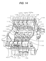
- Fig. 13 and Fig. 14 show an embodiment of a carriage in which the ink cartridges are mounted.
- the carriage is structured so that a plurality of ink cartridges (one black ink cartridge and three color ink cartridges in this embodiment) may be mounted in the carriage.
- first mounting region 120 which is somewhat larger than others in width, is disposed on one side; second, third and fourth mounting regions 121, 122 and 123, which are equal in width to each other, are defined by ribs 124 through 126 and ribs 127 through 129, provided at opposite sides of the carriage, so as to be adjacent to the first mounting region 120.
- each cartridge mounting region has the ink supply needle 102 communicating with the recording head 101, the pressing member(the leaf spring 103 in this embodiment) in a region separated from a region where the ink supply needle 102 is disposed, and the positioning protrusion 104 provided between the leaf spring 103 and the ink supply needle 102 to extend in the cartridge insertion/pull-out direction. Further, a recess 107' is formed to guide the side portions of the ink cartridge in the retaining member 5 side.
- the electrodes 106 are disposed on a side wall 105 close to the ink supply needle 102.
- the recess 107 is formed to be engaged with the protrusion 5a of the retaining member 5.
- a recess 107a is formed to be engaged with a protrusion 5b of the retaining member 5 (Figs. 1 and 2) protruding from a side portion of the retaining member 5.
- a region of the carriage with which the retaining member 6 is contacted is formed with a recess 109 for guiding side portions of the retaining member 6, and a recess 109a engaged with a protrusion 6b of the retaining member 6 (Figs. 1 and 2) protruding from a side portion of the retaining member 6.
- the positioning protrusion 104 is structured so that, as shown in Fig. 15A, a side portion 104a extending parallel with the front surface of the cartridge is formed so as to ensure the positioning reliability and the strength of the thin and long protrusion 104.
- the slit portion 9 of the ink cartridge is structured so that at least the cartridge insertion direction leading end thereof is formed with a recess 9a opposing the side portion 104a, the recess 9a being open to the front surface side of the ink cartridge.
- the ink cartridge of a large capacity type mounted to the first mounting region 120 large in width has basically the same structure as that of the above-mentioned embodiment (the ink cartridge of a small capacity type shown in Figs. 1 and 2), as shown in Figs. 16A to 16C.
- a container body 2' is configured to have an opened surface having the same shape as that of the container body 2, but only a depth W thereof is set to be larger than that of the container body 2. Accordingly, by only altering the depth W of the container body 2', it is possible to increase the ink quantity to be contained in the container body 2'.
- the members that have the same function as those shown in Fig. 1 and Fig. 2 are referenced correspondingly but marked with a prime.
- Layout centers of an ink supply port 4' and memory means 7', particularly, electrodes 7a' of the memory means 7' are set to be located at a predetermined position W1 from the surface of the container body 2', that is, the bottom, in the same manner as that in the other cartridges. That is, the distance W1 of the layout center of the ink supply port 4' from the surface of the container body 2' in the large capacity ink cartridge 1' is set to be equal to the distance W1 of the layout center of the ink supply port 4 from the surface of the container body 2 in the small capacity ink cartridge 1.
- the distance W1 of the layout center of the electrodes 7a' from the surface of the container body 2' in the large capacity ink cartridge 1' is set to be equal to the distance W1 of the layout center of the electrodes 7a from the surface of the container body 2 in the small capacity ink cartridge 1.
- a cartridge-identifying block 70' is mounted in the container body 2' at the surface side. Accordingly, the cartridge-identifying block 70' is disposed in a position the same as the other cartridges.
- Retaining members 5' and 6' are disposed at an offset position toward the surface of the container body 2' in the same manner as the ink supply port 4' so as to surely apply a pressing force onto the ink supply port 4' when the cartridge is mounted.
- a width W2 of the retaining member 6' to be located closer to a user when the user mounts or removes the ink cartridge 1' to the carriage, is preferably larger than a width W3 of the retaining member 5' in view of operationability. That is, the width W2 of the retaining member 6' on which the user's thumb is placed is preferably larger than the width W3 of the retaining member 5' on which the user's forefinger is placed.
- a tongue portion 130a may be formed integrally with a decorative film 130 bonded to the surface of the film 57' of the container body 2' so that the tongue portion 130a corresponds in region to ink injection holes 20' and 21' (Fig. 17A) and seals the ink injection holes 20' and 21'.
- Fig. 18 shows a state in which the ink cartridges 1 of a small capacity type and the ink cartridge 1' of a large capacity type as described above are mounted in the cartridge 100.
- the configuration is made so that a plurality of ink cartridges are mounted in a carriage.
- configuration may be made such that a plurality of carriages are provided, and one or more cartridge(s) is mounted to each of the plural carriages.
- an ink cartridge that is detachably insertable to an ink supply needle and that can be mounted in a precise position at which communication with memory means provided in the cartridge can be ensured. Also, it is possible to provide an ink cartridge, the capacity of which can be easily changed while using common component parts.
- the present invention provides, at least, the following arrangements:
Abstract
Description
- The present invention relates to an ink cartridge for supplying ink, under a proper negative pressure state, to a recording head ejecting ink drops in response to printing signals.
- A recording device, in which an ink container is mounted detachably in a carriage having an ink jet recording head, has a retaining mechanism that prevents removal of the cartridge due to movement of the carriage during printing operation, and that enables easy disengagement of the cartridge by an external operation.
- For example, as disclosed in JP-A-10-44451, such a retaining mechanism is structured so that a protrusion portion to be engaged with an ink cartridge holder is formed on one surface of opposite side surfaces of an ink tank, while a pawl is formed on a pivotable lever on the other surface. In a state that the protrusion portion is brought into engagement with the ink cartridge holder, the pawl is brought into engagement with the ink cartridge holder by moving the other surface with the protrusion portion as a rotational fulcrum.
- However, the retaining mechanism adapted to mount the ink cartridge by rotation of the cartridge is difficult to be applied to an ink container which forms an ink flow passage via an ink supply needle communicating with a recording head.
- That is, because the ink supply needle has a predetermined length for ensuring a reliable communication with the ink container, there is a danger that the ink supply needle may be bent or damaged when it receives an external force in a direction other than the axial direction. Accordingly, the ink container has to be moved parallel to the longitudinal direction of the ink supply needle.
- Further, as disclosed in JP- A-9-11500, there is proposed an ink cartridge such that elastically deformable levers each having a pawl for engagement with an ink cartridge holder are formed in opposite surfaces of a container storing ink therein so as to enable insertion of the ink cartridge onto the ink supply needle.
- Furthermore, as disclosed in JP-A-2001-105587, there is proposed an ink cartridge such that a thin and rectangular parallelepiped container for storing ink has a latch member on a front-surface-side wall in the longitudinal direction, and protrusion portions, for guiding the insertion of the cartridge, on opposite walls in the vicinity of the front-surface-side wall.
- Furthermore, EP-A-0 997 297 discloses an attachment/detachment mechanism for an ink cartridge, wherein an overhang member of the ink cartridge engages the printing apparatus to assist attaching and detaching and is disengaged in the attached state.
- Moreover, EP-A-1 004 449 discloses a retaining mechanism, wherein the ink cartridge is retained in a carriage in that a cover of the carriage engages the body of the carriage.
- However, an ink cartridge provided with memory means storing information concerning the ink cartridge or the like requires reliable connection to minute electrodes, and thus requires reliable positioning.
- The present invention was made in view of the above-noted problems, and an object of the present invention is to provide an ink cartridge that is detachably insertable onto an ink supply needle and that can be mounted in a precise position at which communication with memory means provided in the cartridge can be ensured.
- Another object of the invention is to provide an ink cartridge, the capacity of which can be easily changed while using common component parts.
- A further object of the invention is to provide an ink jet recording apparatus in combination with such an ink cartridge.
- Yet another object of the present invention is to provide ink cartridges respectively storing ink of different kinds to be mounted to an ink jet recording device as a set.
- These objects are solved by means of an ink cartridge as claimed in
claim 1, an ink jet recording device as claimed inclaim 29, and a set of ink cartridges according toclaim 36. - Preferred optional features are set forth in the dependent claims.
-
- Fig. 1A and Fig. 1B are views showing front-side and rear-side external appearances, respectively, of an ink cartridge of a small capacity type according to a first embodiment of the present invention.
- Figs. 2A to 2D are a top view, a front view, a bottom view and a side view, respectively, of the ink cartridge according to Fig. 1.
- Fig. 3 is a perspective view showing assembly of the ink cartridge according to the first embodiment.
- Fig. 4 is a perspective view showing assembly of the ink cartridge according to the first embodiment.
- Fig. 5 is a sectional view showing a carriage in which the ink cartridge is mounted, according to a second embodiment of the invention.
- Fig. 6A and Fig. 6B are views showing a process of mounting the ink cartridge in the carriage.
- Fig. 7 is a perspective view showing a structure of a bottom of a container body forming the ink cartridge.
- Fig. 8 is a perspective view showing the structure of the opened surface of the container body forming the ink carriage.
- Fig. 9A is a perspective view showing a structure of the front surface of the container body forming the ink cartridge; and Fig. 9B is a view showing a through hole formed in a groove for communication.
- Fig. 10 is an enlarged, sectional view showing the structure of a chamber storing negative-pressure generating means.
- Fig. 11 is an enlarged, sectional view showing the structure of an air communication valve storage chamber.
- Fig. 12A and Fig. 12B are a perspective view and a front view, respectively, showing an example of a cartridge-identifying block.
- Fig. 13 is a perspective view showing an example of a carriage structured so that a plurality of ink cartridges can be stored in the cartridge.
- Fig. 14 is a perspective view showing the carriage viewed from a different direction.
- Fig. 15A and Fig. 15B are enlarged views showing the vicinity of an ink supply needle of the carriage and the vicinity of an ink supply port of the ink cartridge, respectively.
- Fig. 16A to Fig. 16C are perspective views and a bottom view, respectively, showing an ink cartridge of a large-capacity type according to a third embodiment of the present invention.
- Fig. 17A to Fig. 17B are views, respectively, showing a structure of ink injection holes of the ink cartridge of a large-capacity type.
- Fig. 18 is a view showing a state in which ink cartridges of a small-capacity type and a large-capacity type are mounted in the cartridge.
- Fig. 19A is a perspective view showing an example of a memory device, and Fig. 19B is a perspective view showing another example of the memory device.
- Fig. 20 is a perspective view showing an ink cartridge according to yet another embodiment of the present invention.
- Fig. 21A is a perspective view showing yet another example of the memory device, and Fig. 21B is a perspective view showing still another example of the memory device.
- Fig. 22A is a front view of an ink cartridge according to yet another embodiment of the present invention, and Fig. 22B is enlarged, partial view of the ink cartridge.
-
- Preferred embodiments of the present invention will be described below with reference to the accompanying drawings.
- Figs. 1A and 1B and Figs. 2A to 2D show an external appearance of an ink cartridge according to a first embodiment of the present invention. Fig. 3 and Fig. 4 are perspective views showing assembly of the ink cartridge. The
ink cartridge 1 is mainly constituted by a thin andrectangular container body 2 in a box-like shape having an open one surface, and acover member 3 for sealing the open one surface. Anink supply port 4 is formed to be located at a leading end side in an insertion direction of the cartridge 1 (in this embodiment, on the bottom surface of thecontainer body 2 at an offset position in the longitudinal direction of the container body 2). Retainingmembers container body 2 in upper portions of the opposite walls which serve as a forward side and a rearward side respectively when theink cartridge 1 is inserted or pulled out. - The retaining
member 5 located closer to the ink supply port is formed to have a rotational fulcrum at an insertion direction leading end portion (at a portion slightly higher than the lower end of the cartridge in this embodiment), and an openable upper potion that can be open outwardly. The other, opposite retainingmember 6 is formed to assist the holding of the cartridge in cooperation with the retainingmember 5. Each of these retainingmembers member - Further, a memory means 7 is provided under the retaining
member 5 located closer to the ink supply port. The memory means 7 has electrodes 7a on an exposed surface of a board, which are arrayed into two upper and lower rows, and a semiconductor memory element mounted on the rear surface of the board and connected to the electrodes 7a. On the other hand, avalve storage chamber 8 is formed under the other retainingmember 6. - A
slit portion 9 is formed in the vicinity of theink supply port 4 and in a central region of the container so that theslit portion 9 opens at least into the leading end of the cartridge and extends in the cartridge insertion/pull-out direction. Theslit portion 9 has a length and a width such as to regulate the ink cartridge to orient the opened surface of theink supply port 4 perpendicularly to an ink supply needle at least before the leading end of theink supply port 4 reaches the ink supply needle of the carriage. - On the other hand, the
carriage 100 to which the cartridge is to be mounted is provided with a recording head 101 disposed in the bottom of thecarriage 100, and an ink supply needle (ink supply needles) 102 communicating with the recording head 101, as shown in Fig. 5. An ink cartridge-pressing member (aleaf spring 103 in this embodiment) is disposed in a region separated from the region where theink supply needle 102 is disposed, and apositioning protrusion 104 is formed between theink supply needle 102 and theleaf spring 103 to extend in the insertion/pull-out direction of the cartridge. Also, electrodes 106 are disposed on a side wall 105 at theink supply needle 102 side, and arecess 107 is formed in the upper portion of the side wall 105 so that therecess 107 is engaged with a protrusion 5a of the retainingmember 5. - By adopting the structure as described above, as shown in Fig. 6A, in case that the
cartridge 1 is inserted into the carriage with theink supply port 4 located at the rear side and thecartridge 1 is pressed against theleaf spring 103, theslit portion 9 is restricted by theprotrusion 104. Accordingly, even though a rotational force is applied to the cartridge 1 (in the direction of arrow A in Fig. 6A) by theleaf spring 103 disposed at an offset position in an attempt to move theink supply port 4 side downward, the posture of the cartridge is restricted to be substantially parallel with the defined insertion/pull-out direction (the vertical direction in this embodiment). - When the
cartridge 1 is further pressed against theleaf spring 103 with a finger placed on the top surface 2b of thecontainer body 2, thecartridge 1 generates a component of the force to press the surface of thecartridge 1, where the memory means 7 is provided, against the electrodes 106 of thecartridge 100, because the top surface 2b of thecontainer body 2 is formed as a slope having an angle with the rear side of the cartridge 1 (that is, the retainingmember 5 side) being higher. Thus, while the electrodes 7a of the memory means 7 are brought into contact with the electrode 106 securely, the ink cartridge can be pressed and inserted to theink supply needle 102. In the process of this pressure insertion, as shown in Fig. 6B, the protrusion 5a of the retainingmember 5 resists the entire elasticity of the retainingmember 5 and then falls into therecess 107 so that the protrusion 5a is engaged with therecess 107. Accordingly, a clear feeling of click is transmitted to the finger so that a user can sense a fact that the cartridge has been mounted in thecarriage 100 securely. - Although the retaining
member 6 may be provided with a protrusion similarly to the protrusion 5a of the retainingmember 5, provision of the protrusion 5a only on the retainingmember 5 of the memory means 7 side can prevent mounting failure of the ink cartridge. This is because, if a click feeling is generated by the retainingmember 6 of the side where the memory means 7 is not provided, the user may erroneously conclude that the cartridge has been mounted properly though the retainingmember 5 of the memory means 7 side is not yet positioned in the proper position, that is, the retainingmember 5 stays at a position where the click feeling is not generated yet. - In a state in which the cartridge is mounted, because the position of the
cartridge 1 in the insertion/pull-out direction is restricted by the protrusion 5a of the retainingmember 5, and the surface of thecartridge 1 where the memory means 7 is provided is pressed against the electrodes 106 of thecarriage 100 by an urging force (a force in the direction of arrow A in Fig. 6A) of thespring 103, the contact between thecartridge 1 and thecarriage 100 is maintained securely regardless of vibration generated during printing. - On the other hand, in the case where the
ink cartridge 1 is to be removed from thecarriage 100 for replacement or the like, the retainingmember 5 is pressed resiliently toward thecontainer body 2 so that the retainingmember 5 is rotated about the portion slightly higher than the lower end and acting as the rotational fulcrum. Consequently, the protrusion 5a of the retainingmember 5 is released from therecess 107. When thecartridge 1 is pulled out in this state, thecartridge 1 is guided by the protrusion (the guide piece) 104 and moves parallel with theink supply needle 102 under the influence of an urging force of theleaf spring 103. Accordingly, thecartridge 1 can be removed from thecarriage 100 without having any bending force or the like act on theink supply needle 102. - Fig. 7 and Fig. 8 show an example of a flow passage formed in the
container body 2 constituting the above-mentioned ink cartridge. Thecontainer body 2 is partitioned into upper and lower sections by awall 10 extending substantially horizontally. - The lower section contains a first ink chamber 11. The upper section is defined by a frame 14, with the
wall 10 extending continuously as its bottom. A predetermined gap is formed by separating the frame 14 from a wall 12 of thecontainer body 2 so that the gap forms an air communicating passage 13. The frame 14 is further divided into two sections by avertical wall 15 while a communication port 15a formed in the bottom portion of the frame 14 is left. One of the two sections is formed as a second ink chamber 16, while the other is formed as athird ink chamber 17. - A
suction passage 18 is formed in the section of the first ink chamber 11 below the second ink chamber 16, while thesuction passage 18 connects a bottom 16a of the second ink chamber 16 to a bottom 2a of thecontainer body 2. In this embodiment, thesuction passage 18 is further configured such that a recessed portion 18c (Fig. 9) is formed in a front surface of thecontainer body 2, and the recessed portion 18c is sealed with an air impermeable film 57. - A
wall 19 including communication ports 19a and 19b is formed at a lower portion of thesuction passage 18. Aninjection hole 20 for injecting ink into thecontainer body 2 from an exterior is formed at a portion opposite to one end of thesuction passage 18, while anotherhole 21 communicating with the first ink chamber 11 is formed parallel with theinjection hole 20. - The
third ink chamber 17 is partitioned bywalls third ink chamber 17, a fourth ink chamber 23 is defined bywalls valve storage chamber 33 is defined by the wall 24 (Fig. 10). - The
partitioning wall 26 having a communication port 26a is provided between the lower portion of thewall 24 and thewall 10. Thepartitioning wall 27 having a communication port 27a at its lower portion is provided so that anink passage 28 is formed between the partitioningwall 27 and the frame 14. The upper portion of theink passage 28 communicates with a front surface side of theink cartridge 1 through a throughhole 29 serving as a filter chamber. In the throughhole 29, a filter 55 (Fig. 3) made of a porous material is inserted. In Fig. 8, reference numeral 2c indicates a recess for storing the memory means 7. - As shown in Fig. 8, the through
hole 29 is defined by awall 30 continuous to thewall 27, communicates with the upper end of theink passage 28 through a recess 29a, and further communicates, via a water-drop-like recess 30a (Fig.9) in the front surface of thecontainer body 2, with a recess 24a in an upper portion of the flow passage partitioned between awall 34 located in a rear surface of the differential-pressure-valve storage chamber 33, and thewall 24. - A lower portion of the differential-pressure-
valve storage chamber 33 and theink supply port 4 are connected to each other by a flow passage that is constituted by a recess 35 (Fig. 9) formed in the front surface of thecontainer body 2 and the air impermeable film 57 (Fig. 10) covering therecess 35. - As shown in Fig. 9A, a
narrow groove 36, a wide groove 37 and arecess 38 are formed in the front surface of thecontainer body 2. Thenarrow groove 36 meanders so as to provide the largest possible flow resistance. The wide groove 37 is disposed around thenarrow groove 36. Therecess 38 is rectangular in shape and disposed in an area opposite to the second ink chamber 16. Aframe 39 and ribs 40 are formed in therectangular recess 38 so as to be slightly lower in height than an open surface of therectangular recess 38. An air permeable film (not shown) having an ink repellent property and air permeability is stretched and bonded to theseframe 39 and ribs 40, so that an air communication chamber is defined. A throughhole 41 is formed at the bottom of therecess 38, and communicated with a slender region 43 (Fig. 7) defined by a wall 42 of the second ink camber 16. Thenarrow groove 36 communicates with therecess 38 at a position closer to the front surface side than the air permeable film. The other end of the region 43 communicates with thevalve storage chamber 8 through a through hole 44, a communicating groove 45 and a through hole 46 (Fig.9B). - A window 8a is formed and opened in the leading end of the
valve storage chamber 8 in the cartridge insertion direction (in the lower portion of thevalve storage chamber 8 in the embodiment, as shown in Fig. 8) so that a cartridge-identifying block 7 (as shown in Fig. 3, Fig. 4 and Fig. 12) can be mounted as described latter. The cartridge-identifyingblock 70 permits insertion of a valve operating rod and a plurality of identifying pieces 110, 111 and 112 (as shown in Fig. 5) provided on thecarriage 100 of the recording device body. - Fig. 10 is a sectional view showing a structure of the vicinity of the differential-pressure-
valve storage chamber 33. Aspring 50 and amembrane valve 52 are stored in the differential-pressure-valve storage chamber 33. Themembrane valve 52 is formed of an elastically deformable material, such as elastomer, and has a throughhole 51 at its center. Themembrane valve 52 includes an annular thick portion 52a circumferentially provided, and aframe 54 formed integrally with the thick portion 52a. Themembrane value 52 is fixed to thecontainer body 2 via theframe 54. Thespring 50 is supported at one end by a spring receiving portion 52b of themembrane valve 52, and at the other end by a spring receiving portion 53a of a lid member 53, which is fitted to the opening of thestorage chamber 33. - Reference numerals 56 and 57 represent air impermeable films bonded onto the front surface side and the opened surface side of the
container body 2. The air impermeable film 56 is bonded to thewall 10, the frame 14 and thewalls narrow groove 36 formed in the front surface of thecontainer body 2 and the differential-pressure-valve storage chamber 33 are covered with the air impermeable film 57. - In this structure, ink which has passed through ink passing ports 34a is blocked by the
membrane valve 52. When a pressure at theink supply port 4 is lowered in this state, themembrane valve 52 moves apart from a valve seat 34b against an urging force of thespring 50, so that the ink passes through the throughhole 51 and flows to theink supply port 4 via the flow passage formed by therecess 35. - When an ink pressure at the
ink supply port 4 is increased to a predetermined value, themembrane valve 52 is brought into resilient contact with the valve seat 34b by the urging force of thespring 50. As a result, the ink flow is interrupted. By repeating this operation, ink is discharged to the ink supply port, while a constant negative pressure is maintained. - Fig. 11 is a sectional view showing a structure of the
valve storage camber 8 for communication with the air. A throughhole 60 is bored in the wall defining thevalve storage chamber 8. A pressing member 61 formed of an elastic material, such as rubber, is movably inserted into the throughhole 60 in a state that the circumference of the pressing member 61 is supported by thecontainer body 2. Avalve body 65 is provided at the leading end of the pressing member 61 in the insertion direction, so that thevalve body 65 is supported by anelastic member 62, such as a leaf spring, having a lower end fixed by a protrusion 63 and a center portion restricted by a protrusion 64. Thevalve body 65 is constantly urged toward the throughhole 60. - The cartridge-identifying
block 70 shown in Fig. 12 is located and installed in the other surface of the pressing member 61. - The cartridge-identifying
block 70 is constituted by a base which is fixed to a recess 80 of the cartridge (Fig. 9) by means of pawls 70a and 70b. The base is formed with a plurality of grooves (threegrooves 71, 72 and 73 in the embodiment), and anarm 74. Each of thesegrooves 71, 72 and 73 extends parallel to the cartridge insertion direction and has a predetermined width in the widthwise direction of the cartridge. In this embodiment, thearm 74 is provided in thegroove 72 on the ink cartridge insertion side (the trailing end of the insertion direction in the embodiment) for pressing the pressing member 61. Depths of thesegrooves 71, 72 and 73 are set so that the thesegrooves 71, 72 and 73 can receive respective identifying pieces. - The
arm 74 is pivotable about a fulcrum 74a so as to be located further inwardly, and has a pull-out side (the leading end portion of thearm 74 in the insertion direction in this embodiment) that protrudes obliquely into an insertion path of an operating rod 113 (Fig. 14). - Further, protruding portions 71a, 72a and 73a are formed in the
respective grooves 71, 72 and 73 so as to face the upper end of identifying pieces 110, 111 and 112 of the carriage 110 respectively. - In the structure as described above, while the position of the
arm 74 is fixed, the positions of the protruding portions 71a, 72a and 73a for engagement and the positions of the upper ends of the corresponding identifying pieces 110, 111 and 112 are set in accordance with the kind of ink contained in the cartridge. Accordingly, it is possible to prevent the cartridge from being mounted erroneously. If the positions of the protruding portions 71a, 72a and 73a for engagement can be changed not only in the insertion direction of the cartridge but also in the width direction of the cartridge, it is made possible to adopt a three-dimensional layout structure for the protruding portions 71a, 72a and 73a for engagement. Accordingly, it is possible to identify a large number of kinds of ink without increasing the identifying region forming area. - Fig. 13 and Fig. 14 show an embodiment of a carriage in which the ink cartridges are mounted. The carriage is structured so that a plurality of ink cartridges (one black ink cartridge and three color ink cartridges in this embodiment) may be mounted in the carriage.
- That is, a first mounting
region 120, which is somewhat larger than others in width, is disposed on one side; second, third and fourth mountingregions 121, 122 and 123, which are equal in width to each other, are defined byribs 124 through 126 and ribs 127 through 129, provided at opposite sides of the carriage, so as to be adjacent to the first mountingregion 120. - As described with reference to Fig. 5, each cartridge mounting region has the
ink supply needle 102 communicating with the recording head 101, the pressing member(theleaf spring 103 in this embodiment) in a region separated from a region where theink supply needle 102 is disposed, and thepositioning protrusion 104 provided between theleaf spring 103 and theink supply needle 102 to extend in the cartridge insertion/pull-out direction. Further, a recess 107' is formed to guide the side portions of the ink cartridge in the retainingmember 5 side. - Further, the electrodes 106 are disposed on a side wall 105 close to the
ink supply needle 102. In the upper portion of the side wall 105, therecess 107 is formed to be engaged with the protrusion 5a of the retainingmember 5. In a vicinity of therecess 107, arecess 107a is formed to be engaged with a protrusion 5b of the retaining member 5 (Figs. 1 and 2) protruding from a side portion of the retainingmember 5. - Similarly, as shown in Figs. 5 and 14, a region of the carriage with which the retaining
member 6 is contacted, is formed with arecess 109 for guiding side portions of the retainingmember 6, and a recess 109a engaged with a protrusion 6b of the retaining member 6 (Figs. 1 and 2) protruding from a side portion of the retainingmember 6. - In the embodiment, the
positioning protrusion 104 is structured so that, as shown in Fig. 15A, a side portion 104a extending parallel with the front surface of the cartridge is formed so as to ensure the positioning reliability and the strength of the thin andlong protrusion 104. Corresponding to thepositioning protrusion 104, as shown in Fig.15B, theslit portion 9 of the ink cartridge is structured so that at least the cartridge insertion direction leading end thereof is formed with a recess 9a opposing the side portion 104a, the recess 9a being open to the front surface side of the ink cartridge. - Ribs 102a brought into engagement with ribs 4a, each of which is formed into a U-shape in section and between which the
ink supply port 4 of the ink cartridge is sandwiched, are formed around theink supply needle 102. By these ribs, it is possible to maintain the cartridge in a state that theink supply needle 102 is inserted into theink supply port 4. - The ink cartridge of a large capacity type mounted to the first mounting
region 120 large in width has basically the same structure as that of the above-mentioned embodiment (the ink cartridge of a small capacity type shown in Figs. 1 and 2), as shown in Figs. 16A to 16C. A container body 2' is configured to have an opened surface having the same shape as that of thecontainer body 2, but only a depth W thereof is set to be larger than that of thecontainer body 2. Accordingly, by only altering the depth W of the container body 2', it is possible to increase the ink quantity to be contained in the container body 2'. Incidentally, in Figs. 16A and 16B, the members that have the same function as those shown in Fig. 1 and Fig. 2 are referenced correspondingly but marked with a prime. - Layout centers of an ink supply port 4' and memory means 7', particularly, electrodes 7a' of the memory means 7' are set to be located at a predetermined position W1 from the surface of the container body 2', that is, the bottom, in the same manner as that in the other cartridges. That is, the distance W1 of the layout center of the ink supply port 4' from the surface of the container body 2' in the large capacity ink cartridge 1' is set to be equal to the distance W1 of the layout center of the
ink supply port 4 from the surface of thecontainer body 2 in the smallcapacity ink cartridge 1. Similarly, the distance W1 of the layout center of the electrodes 7a' from the surface of the container body 2' in the large capacity ink cartridge 1' is set to be equal to the distance W1 of the layout center of the electrodes 7a from the surface of thecontainer body 2 in the smallcapacity ink cartridge 1. In addition, a cartridge-identifying block 70' is mounted in the container body 2' at the surface side. Accordingly, the cartridge-identifying block 70' is disposed in a position the same as the other cartridges. - Retaining members 5' and 6' are disposed at an offset position toward the surface of the container body 2' in the same manner as the ink supply port 4' so as to surely apply a pressing force onto the ink supply port 4' when the cartridge is mounted. In addition, as shown in Fig. 16A, a width W2 of the retaining member 6', to be located closer to a user when the user mounts or removes the ink cartridge 1' to the carriage, is preferably larger than a width W3 of the retaining member 5' in view of operationability. That is, the width W2 of the retaining member 6' on which the user's thumb is placed is preferably larger than the width W3 of the retaining member 5' on which the user's forefinger is placed. As shown in Fig. 17B, a tongue portion 130a may be formed integrally with a
decorative film 130 bonded to the surface of the film 57' of the container body 2' so that the tongue portion 130a corresponds in region to ink injection holes 20' and 21' (Fig. 17A) and seals the ink injection holes 20' and 21'. - Fig. 18 shows a state in which the
ink cartridges 1 of a small capacity type and the ink cartridge 1' of a large capacity type as described above are mounted in thecartridge 100. - In the above-described embodiment, description has been made about the case in which a differential-pressure valve is used as negative pressure generating means. However, it is apparent that the same effect can be also obtained by using a porous material such as a sponge impregnated with ink so as to maintain the negative pressure by means of the capillary force of the pores.
- Also, in the above-described embodiment, the configuration is made so that a plurality of ink cartridges are mounted in a carriage. Alternatively, configuration may be made such that a plurality of carriages are provided, and one or more cartridge(s) is mounted to each of the plural carriages.
- As described above, according to the present invention, it is possible to provide an ink cartridge that is detachably insertable to an ink supply needle and that can be mounted in a precise position at which communication with memory means provided in the cartridge can be ensured. Also, it is possible to provide an ink cartridge, the capacity of which can be easily changed while using common component parts.
- As described above, the present invention provides, at least, the following arrangements:
- (1) An ink cartridge comprising: a container body
having a first wall; at least one electrode connected to a
memory device, the at least one electrode being fixed
relative to the wall; and an engagement portion movable
relative to the wall and being higher in a Y-axis direction
than the at least one electrode.
By way of not-limiting example, as shown in Fig. 2c, a
movable engagement protrusion 5a is higher in a Y-axis
direction than the electrodes 7a. In this embodiment shown
in Fig. 2A to 2C, the movable engagement portion is in the
form of the protrusion 5a which is formed on the retaining
member 5 in the form of a pivotable lever and which is to be engaged with therecess 107 of thecarriage 100, but the present invention should not be restricted thereto or thereby. By way of non-limiting example, the engagement portion could be formed as a recess in the retainingmember 5. In this case, a mating engagement portion in thecarriage 100 is preferably formed as a protrusion fit into the recess. Further, the engagement portion could be directly formed on the wall of thecontainer body 2, not via the retainingmember 5. For example, an elastic protrusion may be attached to the wall of thecontainer body 2 to serve as the engagement portion. More preferably, a spring biased member having a rounded distal end may be provided to the wall of thecontainer body 2. In this case, the rounded distal end is protruded from the wall of thecontainer body 2 by the biasing force of a spring so that the spring biased member, when engaged with therecess 107, provides a predetermined retaining force to hold theink cartridge 1 in thecarriage 100. During the insertion or removal of theink cartridge 1 from thecarriage 100, the rounded distal end can be retracted toward the interior of thecontainer body 2 against the biasing force of the spring for disengagement from therecess 107 because of the rounded shape of the distal end. Further, as shown in Figs. 22A and 22B, aprotrusion 131 may be formed on a relatively rigid portion of thecontainer body 2 so that theprotrusion 131 can be fitted into therecess 107 of thecarriage 100 using the elasticity of, at least, portions of thecarriage 100 defining therecess 107. That is, using the elasticity of the portions of thecarriage 100 defining therecess 107, theink cartridge 1 having theprotrusion 131 can be inserted into, fixed onto and removed from thecarriage 100. - (2) In an ink cartridge constructed according to (1),
the engagement portion is substantially aligned with the at
least one electrode in the Y-axis direction. By way of non-limiting
example, as shown in Fig. 2C, the engagement
protrusion 5a is aligned with the electrodes 7a in the Y-axis
direction. This arrangement remarkably contributes to
reliable contact between the electrodes 7a of the
ink cartridge 1 and the electrodes 106 of thecarriage 100. - (3) In an ink cartridge constructed according to (1) or
(2), the wall may have a recessed portion in which the at
least one electrode is located. By way of non-limiting
example, as shown in Figs. 1A and 7, the wall of the
container body 2 has arecess 2a for storing a substrate (the memory device 7), the substrate having a first exposed surface on which the electrodes 7a are disposed and a second, hidden surface on which main circuit components of thememory device 7, electrically connected to the electrodes 7a are mounted. Accordingly, the electrodes 7a are located in the recessedportion 2a. In addition, the main circuit components of thememory device 7 may be disposed at a location other than therecess 2a using a FPC. For example, as shown in Figs. 19A, amemory device 107 includes asubstrate 107s,electrodes 107a formed on thesubstrate 107s, a flexible printedcircuit 107f in the form of a flexible sheet, and main circuit components (in the form of a chip) 107m that are electrically connected to theelectrodes 107a via theFPC 107f and that are mounted on a hidden surface of theFPC 107f. Thememory device 107 can be mounted onto theink cartridge 1 such that the substrate including theelectrodes 107a is mounted on a wall of theink cartridge 1 and themain circuit components 107f of thememory device 107 are mounted on another wall other than the wall mounting thesubstrate 107s and theelectrodes 107a thereon. Further, the substrate can be dispensed with using the FPC. For example, as shown in Fig. 19B, thememory device 107 can be constructed without using thesubstrate 107s. That is, theelectrodes 107a can be formed directly on theFPC 107f. - (4) In an ink cartridge constructed according to (1) or
(2), the wall may have a protruded portion onto which the at
least one electrode is located. The protruded portion may be
formed on the wall of the
container 2 in place of therecess 2a so that the electrodes 7a can be located on the protruded portion. For example, as shown in Fig. 20, a projecting portion 2d may be formed on thecontainer body 2, which has a distal end surface extending parallel to the insertion direction of theink cartridge 1. The electrodes 7a may be disposed on this distal end surface of the projecting portion 2d. - (5) In an ink cartridge constructed according to (1) or
(2), the wall may have a first surface part on which at least
one electrode is disposed, and a second surface part on which
a pivotable lever having the engagement portion is disposed.
By way of not-limiting example, in the case of the first
embodiment, the first surface part is defined by the
recess 2a of the wall, and the second surface part is defined by the surface of the wall located above therecess 2a. - (6) In an ink cartridge constructed according to (5), the first surface part is flush with the second surface part. In the first embodiment, the first surface part is somewhat recessed from the second surface part, but these first and second surface parts may be flush with each other completely to provide a planar surface.
- (7) In an ink cartridge constructed according to (5), the first and second surface parts has a level difference therebetween. A small level difference between the first and second surface parts is provided in the first embodiment. This small level difference may be made larger.
- (8) In an ink cartridge constructed according to (5), the first surface part may be inclined relative to the second surface part. In the first embodiment, the first surface part is parallel to the second surface part, but may be inclined relative to the second surface part. By way of non-limiting example, Fig. 20 shows an ink cartridge having the first surface part inclined relative to the second surface part.
- (9) In an ink cartridge constructed according to any
one of (1) to (8), the main circuit components of the memory
device are disposed on the first wall. By way of non-limiting
example, in the first embodiment, the main
components of the memory device are stored in the recess 2c
of the wall of the
container body 2. - (10) In an ink cartridge according to any one of (1) to
(8), the main circuit components of the memory device may be
disposed on a second wall other than the first wall. By way
of non-limiting example, the main circuit components of the
memory device 7 could be disposed on a side wall of thecontainer body 2 using a FPC - (11) In an ink cartridge according to any one of (1) to
(10), the at least one electrode may have a width and a
length larger than the width. For example, as shown in Fig.
2C, a length L of the
electrode 7 in the Y-axis direction is larger than a width W of the electrode 7a in the Z-axis direction. In addition, as shown in Figs. 21A and 21B, each of theelectrodes 107a having the larger length and smaller width may be formed into an oval or oblong shape. - (12) In an ink cartridge according to any one of (1) to
(11), an ink supply port is provided, the ink supply port
having an axis defining a first side and a second side
opposite from the first side in an X-axis direction. For
example, in the first embodiment, the
ink cartridge 1 has theink supply port 4 having an axis A, and the axis defines a first side B and a second side C opposite from the first side B with respect to the axis A in an X-axis direction. - (13) In an ink cartridge according to (12), the at least one electrode and the engagement portion are located in the first side. For example, in the first embodiment, the electrodes 7a and the engagement portion 5a are located in the first side B.
- (14) In an ink cartridge according to (12) or (13), the at least one electrode and the engagement portion are located on the axis of the ink supply port as viewed in a Y-Z plane. By way of non-limiting example, a central electrode 7a in the upper row is located on the axis A, and the engagement portion 5a is also located on the axis A, as shown in Fig. 2C.
- (15) In an ink cartridge according to(14), a center of the at least one electrode and a center of the engagement portion are preferably located on the axis of the ink supply port as viewed in the Y-Z plane. By way of non-limiting example, in the first embodiment, a center of the central electrode 7a in the upper row and a center of the engagement portion 5a are located on the axis A as shown in Fig. 2C.
- (16) In an ink cartridge according to (12) or (13), the at least one electrode may include plural electrodes arrayed into at least one row, and the at least one row and the engagement portion are preferably located on the axis of the ink supply port as viewed in a Y-Z plane. By way of non-limiting example, in the first embodiment, two upper and lower rows of the electrodes 7a are both located on the axis A as shown in Fig. 2C.
- (17) In an ink cartridge according to (16), a center of the at least one row and a center of the engagement portion are preferably located on the axis of the ink supply port as viewed in the Y-Z plane. By way of non-limiting example, in the first embodiment, a center of each of the two upper and lower rows is located on the axis A as shown in Fig. 2C since the electrodes 7a in each of upper and lower rows are symmetrically arranged with respect to the axis A as shown in Fig. 2C.
- (18) In an ink cartridge according to any one of (12) to
(17), the axis of the ink supply port may be located at a
central position with respect to the container body in a Z-axis
direction. The small capacity
type ink cartridge 1 employs this arrangement. - (19) In an ink cartridge according to any one of (12) to (17), the axis of the ink supply port may be located at an offset position with respect to the container body in a Z-axis direction. The large capacity type ink cartridge 1' employs this arrangement.
- (20) In an ink cartridge according to any one of (5) to
(8), an ink supply port having an axis is provided, and at
least one of the first and second surface parts are inclined
relative to the axis to present at least in part a tapered
configuration of the first wall. For example, in the first
embodiment, the wall of the container, where the electrodes
7a and the retaining
member 5 having the engagement protrusion 5a are disposed, extends in parallel to the axis A of theink supply port 4. However, the invention should not be restricted thereto or thereby. By way of non-limiting example, that wall may be inclined in part or entirely with respect to the axis A of theink supply port 4, so that a portion of the wall, closer to theink supply port 4 than another portion of the wall in the Y-axis direction, is located closer to the axis A than the other portion of the wall in the X-axis direction. In this case, the electrodes 7a may be disposed on the inclined portion of the wall to be inclined with respect to the axis A. - (21) In an ink cartridge according to any one of (12) to
(20), a slot is preferably provided, which extends
substantially parallel to the axis of the ink supply port and
located in the second side. By way of non-limiting example,
in the first embodiment, the
slot 9 is formed in thecontainer body 2. - (22) In an ink cartridge according to any one of (1) to
(11), an ink supply port and a slot are provided, the slot
extending in the Y-axis direction, and being located in the
vicinity of the ink supply port. In the first embodiment,
the
slot 9 is formed in the vicinity of theink supply port 4. Theslot 9 is preferably located in the second side, but may be located in the first side. -
- Further aspects of the invention are revealed in the following numbered paragraphs:
- 1. An ink cartridge comprising: a container storing ink therein and having an ink supply port in a leading end side in an insertion direction of the container; memory means having an electrode connectable to a recording device, the electrode being disposed on one of opposite surfaces substantially parallel with the insertion direction of the container; and a retaining member disposed on the one surface, and located at a trailing end side relative to the electrode in the insertion direction, the retaining member being engageable with a recording device.
- 2. An ink cartridge according to
item 1, further comprising a guide member disposed on the other of the opposite surfaces and guidable by the recording device. - 3. An ink cartridge according to
item - 4. An ink cartridge according to
item - 5. An ink jet recording device supplied with ink from an ink cartridge including: a container storing ink therein and having an ink supply port in a leading end side in an insertion direction of the container; memory means having an electrode connectable to a recording device, the electrode being disposed on one of opposite surfaces substantially parallel with the insertion direction of the container; and a retaining member disposed on the one surface, and located at a trailing end side relative to the electrode in the insertion direction, the retaining member being engageable with a recording device, the recording device comprising: an electrode disposed in a side corresponding to a region where the retaining member is provided, and connected to the electrode of the memory means; and an elastic member for applying an urging force substantially parallel to the insertion direction of the ink cartridge.
- 6. An ink jet recording device according to
item 5, further comprising a recess formed in a region opposite to the retaining member, extending in the insertion direction of the ink cartridge, and engageable with a side surface of the retaining member. - 7. An ink jet recording device according to
item - 8. An ink cartridge comprising: a container storing ink therein and having an ink supply port in a leading end side in an insertion direction of the container; memory means having an electrode connectable to a recording device, the electrode being disposed on one of opposite surfaces substantially parallel with the insertion direction of the container; a retaining member disposed on the one surface and located at a trailing end side relative to the electrode in the insertion direction, the retaining member being engageable with the recording device; and a guide recess located substantially in a central region of the container and extending in the insertion direction.
- 9. An ink cartridge according to
item 8, wherein a leading end region of the guide recess in the insertion direction is opened to a front surface side of the container. - 10. An ink jet recording device supplied with ink from an ink cartridge including: a container storing ink therein and having an ink supply port in a leading end side in an insertion direction of the container; memory means having an electrode connectable to a recording device, the electrode being disposed on one of opposite surfaces substantially parallel with the insertion direction of the container; a retaining member disposed on the one surface and located at a trailing end side relative to the electrode in the insertion direction, the retaining member being engageable with the recording device; and a guide recess located substantially in a central region of the container and extending in the insertion direction, said recording device comprising: a guide protrusion engageable with the guide recess; and an elastic member that resists against the insertion of the ink cartridge and that is disposed in a side opposite to the retaining member with respect to the guide protrusion.
- 11. An ink jet recording device according to
item 10, wherein a leading end region of the guide protrusion in the insertion direction of the ink cartridge has a L-shape in section. - 12. A set of ink cartridges respectively storing ink of different kinds, mountable to an ink jet recording device, and each comprising a container body having an ink supply port and a cover member sealing an opened surface of the container body, wherein the ink supply ports, and members, which are disposed on the respective ink cartridges to cooperate with the ink jet recording device, are located at positions equidistanced from side surfaces of the container bodies of the respective ink cartridges.
- 13. A set of ink cartridges according to item 12, wherein the member that cooperates with the ink jet recording device includes at least one of a cartridge identifying block for judging the kind of the ink, the memory means, an air release valve for allowing an ink storage chamber to communicate with the air, and a retaining member for fixing the ink cartridge to the ink inject recording device.
- 14. A set of ink cartridges according to item 12, wherein at least one of the ink cartridges has a larger capacity by way of a greater depth of the container body than the other ink cartridges.
- 15. A set of ink cartridges respectively storing ink of different kinds, mountable to an ink jet recording device, each comprising a container body having an ink supply port and a cover member sealing an opened surface of the container body, wherein the ink supply ports, and members, which are disposed on the respective ink cartridges to cooperate with the ink jet recording device, are located at positions equidistanced from side surfaces of the container bodies of the respective ink cartridges, and wherein a depth of the container body of at least one of the ink cartridges, as measured from the side surface of the container body, is set larger than the rest.
- 16. A set of ink cartridges according to
item 15, wherein the member that cooperates with the ink jet recording device includes at least one of a cartridge identifying block for judging the kind of the ink, the memory means, an air release valve for allowing an ink storage chamber to communicate with the air, and a retaining member for fixing the ink cartridge to the ink inject recording device. - 17. An ink cartridge comprising: a container body having a first wall; at least one electrode connected to main circuit components of a memory device, the at least one electrode being fixed relative to the first wall; and an engagement portion movable relative to the first wall and being higher in a Y-axis direction than the at least one electrode.
- 18. An ink cartridge according to
item 17, wherein the engagement portion is substantially aligned with the at least one electrode in the Y-axis direction. - 19. An ink cartridge according to
item - 20. An ink cartridge according to
item - 21. An ink cartridge according to
item - 22. An ink cartridge according to
item 21, wherein the first surface part is flush with the second surface part. - 23. An ink cartridge according to
item 21, wherein the first and second surface parts has a level difference therebetween. - 24. An ink cartridge according to
item 21, wherein the first surface part is inclined relative to the second surface part. - 25. An ink cartridge according to any one of
items 17 to 24, wherein the main circuit components of the memory device are disposed on the first wall. - 26. An ink cartridge according to any one of
items 17 to 24, wherein the main circuit components of the memory device are disposed on a second wall other than the first wall. - 27. An ink cartridge according to any one of
items 17 to 26, wherein the at least one electrode has a width and a length larger than the width. - 28. An ink cartridge according to any one of
items 17 to 27, further comprising an ink supply port having an axis extending in the Y-axis direction and defining a first side and a second side opposite from the first side in an X-axis direction. - 29. An ink cartridge according to
item 28, wherein the at least one electrode and the engagement portion are located in the first side. - 30. An ink cartridge according to
item - 31. An ink cartridge according to
item 30, wherein a center of the at least one electrode and a center of the engagement portion are located on the axis of the ink supply port as viewed in the Y-Z plane. - 32. An ink cartridge according to
item - 33. An ink cartridge according to item 32, wherein a center of the at least one row and a center of the engagement portion are located on the axis of the ink supply port as viewed in the Y-Z plane.
- 34. An ink cartridge according to any one of
items 28 to 33, wherein the axis of the ink supply port is located at a central position with respect to the container body in a Z-axis direction. - 35. An ink cartridge according to any one of
items 28 to 33, wherein the axis of the ink supply port is located at an offset position with respect to the container body in a Z-axis direction. - 36. An ink cartridge according to any one of
item 21 to 24, further comprising: an ink supply port having an axis extending in the Y-axis direction, wherein at least one of the first and second surface parts are inclined relative to the axis of the ink supply port to present at least in part a tapered configuration of the first wall. - 37. An ink cartridge according to any one of
items 28 to 36, further comprising a slot extending substantially parallel to the axis of the ink supply port and located in the second side. - 38. An ink cartridge according to any one of
items 17 to 27, further comprising: an ink supply port; and a slot extending in the Y-axis direction, and being located in the vicinity of the ink supply port. -
Claims (39)
- An ink cartridge for detachable mounting on a carriage (100) which is reciprocally movable in a recording apparatus and which has an electrode (106), an engagement portion (107) and an ink supply needle (102), the ink cartridge (1) comprising:a container (2) storing ink therein and having an ink supply port (4) connectable to the ink supply needle (102), the ink supply port being located in a leading end side in an insertion direction of the container (2) into the carriage, the container further having first and second walls opposing each other, the first wall being substantially parallel with the insertion direction of the container (2) into the carriage (100),memory means (7) having an electrode (7a) connectable to the electrode (106) of the carriage (100), the electrode of the memory means (7) being disposed on the first wall of the container (2), anda retaining member (5) disposed on the first wall of the container (2), and having an engagement portion (5a) which is located at a trailing end side, with respect to the insertion direction, relative to the electrode (7a) of the memory means (7), and which is engageable with the engagement portion (107) of the carriage (100); whereinthe engagement portion (5a) is movable relative to the first wall of the container (2), andthe electrode (7a) of the memory means (7) is connected to the electrode (106) of the carriage (100) when the engagement portion (5a) of the retaining member (5) is engaged with the engagement portion (107) of the carriage (100) .
- The ink cartridge according to claim 1, further comprising a guide member disposed on the second wall and guidable by the carriage (100) when the container (2) is inserted into the carriage.
- The ink cartridge according to claim 1 or 2, wherein the container (2) is fixable to the carriage (100) exclusively using the retaining member (5) disposed close to the memory means (7).
- The ink cartridge according to claim 1, 2 or 3, wherein the retaining member (5) serves also as a guide member when the container (2) is inserted into the carriage (100).
- The ink cartridge according to any one of claims 1 to 4, wherein the retaining member (5) has side surfaces, both being slidingly guided by the carriage (100) to restrict a position of the first surface of the container (2) in a width direction when the container is inserted into the carriage (100).
- The ink cartridge according to claim 5, wherein the side surface has a sidewards-extending projection portion (5b) which is received in a groove (109) of the carriage (100) to move the engagement portion (5a) of the retaining member (5) toward the engagement portion (107) of the carriage (100) along a plane parallel to the insertion direction and perpendicular to the width direction when the container (2) is inserted into the carriage (100).
- The ink cartridge according to any one of the preceding claims, wherein the ink supply port (4) has an axis, and the electrode (7a) of the memory means (7) is centered relative to the ink supply port axis such that the plane containing the ink supply port axis intersects the electrode (7a) of the memory means (7).
- The ink cartridge according to any one of the preceding claims, further comprising a guide recess (9) located substantially in a central region of the container and extending in the insertion direction.
- The ink cartridge according to claim 8, wherein a leading end region of the guide recess (9) in the insertion direction is opened to a front surface side of the container.
- The ink cartridge according to any one of the preceding claims, wherein the engagement portion (5a) of the retaining member is substantially aligned with the at least one electrode (7a) of the memory means (7) in the Y-axis direction.
- The ink cartridge according to any one of the preceding claims, wherein the first wall has a recessed portion (2a) in which the at least one electrode (7a) of the memory means (7) is located.
- The ink cartridge according to any one of claims 1 to 10, wherein the first wall has a protruded portion onto which the at least one electrode (7a) of the memory means (7) is located.
- The ink cartridge according to any one of the preceding claims, wherein the first wall has a first surface part on which at least one electrode (7a) of the memory means (7) is disposed, and a second surface part on which the retaining member (5) having the engagement portion (5a) of the ink cartridge (1) is disposed.
- The ink cartridge according to claim 13, wherein the first surface part is flush with the second surface part.
- The ink cartridge according to claim 13, wherein the first and second surface parts have a level difference therebetween.
- The ink cartridge according to claim 13, wherein the first surface part is inclined relative to the second surface part.
- The ink cartridge according to any one of the preceding claims, wherein the main circuit components of the memory means (7c) are disposed on the first wall.
- The ink cartridge according to any one of claims 1 to 17, wherein the main circuit components of the memory means (7) are disposed on a second wall other than the first wall.
- The ink cartridge according to any one of the preceding claims, wherein the at least one electrode (7a) of the memory means (7) has a width and a length larger than the width.
- The ink cartridge according to any one of the preceding claims, comprising the ink supply port (4) having an axis extending in a Y-axis direction and defining a first side and a second side opposite from the first side in an X-axis direction.
- The ink cartridge according to claim 20, wherein the at least one electrode (7a) of the memory means and the engagement portion (5a) of the retaining member (5) are located in the first side.
- The ink cartridge according to claim 21, wherein the at least one electrode (7a) of the memory means and the engagement portion (5a) of the retaining member are located on the axis of the ink supply port (4) as viewed in a Y-Z plane.
- The ink cartridge according to claim 22, wherein a center of the at least one electrode (7a) of the memory means (7) and a center of the engagement portion (5a) of the retaining member (5) are located on the axis of the ink supply port as viewed in the Y-Z plane.
- The ink cartridge according to any one of the preceding claims, wherein the at least one electrode (7a) of the memory means (7) includes plural electrodes arrayed into at least one row, and the at least one row and the engagement portion (5a) of the retaining member (5) are located on the axis of the ink supply port (4) as viewed in a Y-Z plane.
- The ink cartridge according to claim 22, wherein a center of the at least one row and a center of the engagement portion (5a) of the retaining member (5) are located on the axis of the ink supply port (4) as viewed in the Y-Z plane.
- The ink cartridge according to any one of the preceding claims, wherein the axis of the ink supply port (4) is located at a central position with respect to the container body (2) in a Z-axis direction.
- The ink cartridge according to any one of the preceding claims, wherein the axis of the ink supply port (4) is located at an offset position with respect to the container body (2) in a Z-axis direction.
- The ink cartridge according to any one of the preceding claims, dependent on claim 13, comprising the ink supply port (4) having an axis extending in the Y-axis direction, wherein at least one of the first and second surface parts are inclined relative to the axis of the ink supply port to present at least in part a tapered configuration of the first wall.
- An ink jet recording device and the ink cartridge according to any one of the preceding claims for supplying said device with ink, the recording device comprising:a carriage (100) which detachably mounts the ink cartridge (1) thereon, which is reciprocally movable in the recording apparatus, and which includes:an electrode (106) disposed in a side corresponding to a region where the retaining member (5) is provided, and connected to the electrode (7a) of the memory means (7);an engagement portion (107) disposed in the same side, and connected to the engagement portion (5a) of the retaining member (5);an ink supply needle (102) connected to the ink supply port (4); andan elastic member (103) for applying an urging force substantially parallel to the insertion direction of the ink cartridge (1) into the carriage (100).
- The ink jet recording device according to claim 29, further comprising a recess (107') formed in a region opposite to the retaining member (5), extending in the insertion direction of the ink cartridge (1), and engageable with a side surface of the retaining member (5).
- The ink jet recording device according to claim 29 or 30, wherein regions for mounting a plurality of the ink cartridges are defined, and electrodes (106) of the carriage (100), which are brought into contact with the electrodes (7b) of a plurality of the memory means (7), are located at positions equidistanced from one side surface of the respective ink cartridges in the respective regions.
- The ink jet recording device according to any one of claims 29 to 31, wherein the carriage (100) further includes guide portions which slidingly guide side surface of the retaining member (5) to restrict a position of the first surface of the container (2) in a width direction when the ink cartridge (1) is inserted into the carriage (100).
- The ink jet recording device according to claim 32, wherein the carriage (100) further includes a groove (107a) which receives a sidewards-extending projection (5b) of the side surface of the retaining member (5) to move the engagement portion (5a) of the retaining member toward the engagement portion (107) of the carriage (100) along a plane parallel to the insertion direction and perpendicular to the width direction when the ink cartridge (1) is inserted into the carriage (100).
- The ink jet recording device according to any one of claims 29 to 33, supplied with ink from an ink cartridge according to claim 8 or 9 or any one of the preceding claims depending on claim 8 or 9, said recording device comprising a guide protrusion (104) engageable with the guide recess (9), wherein the elastic member (103) is disposed in a side opposite to the retaining member (5) with respect to the guide protrusion (104).
- The ink jet recording device according to claim 34, wherein a leading end region of the guide protrusion (104) in the insertion direction of the ink cartridge has a L-shape in section.
- A set of ink cartridges according to any one of claims 1 to 28, respectively storing ink of different kinds, mountable to an ink jet recording device, and each comprising a container body (2) having an ink supply port (4) and a cover member (3) sealing an opened surface of the container body, wherein the ink supply ports (4), and members, which are disposed on the respective ink cartridges to cooperate with the ink jet recording device, are located at positions equidistanced from side surfaces of the container bodies of the respective ink cartridges.
- A set of ink cartridges according to claim 37, wherein the member that cooperates with the ink jet recording device includes at least one of a cartridge identifying block for judging the kind of the ink, the memory means (7), an air release valve for allowing an ink storage chamber to communicate with the air, and the retaining member (5) for fixing the ink cartridge to the ink inject recording device.
- A set of ink cartridges according to claim 36 or 37, wherein at least one of the ink cartridges (1) has a larger capacity by way of a greater depth of the container body (2) than the other ink cartridges.
- A set of ink cartridges according to claim 38, wherein a depth of the container body of at least one of the ink cartridges, as measured from the side surface of the container body, is set larger than the rest.
Priority Applications (2)
| Application Number | Priority Date | Filing Date | Title |
|---|---|---|---|
| EP10164262.7A EP2216179B1 (en) | 2001-04-03 | 2002-04-03 | Ink cartridge, ink jet recording apparatus and set of ink cartridges |
| DE20221597U DE20221597U1 (en) | 2001-04-03 | 2002-04-03 | Ink cartridge for supply of ink in ink-jet recording device uses memory means with electrodes to indicate correct insertion of cartridge into holder |
Applications Claiming Priority (9)
| Application Number | Priority Date | Filing Date | Title |
|---|---|---|---|
| JP2001104526 | 2001-04-03 | ||
| JP2001104526 | 2001-04-03 | ||
| JP2001149315 | 2001-05-18 | ||
| JP2001149315 | 2001-05-18 | ||
| JP2001149788 | 2001-05-18 | ||
| JP2001149788A JP3815254B2 (en) | 2001-05-18 | 2001-05-18 | ink cartridge |
| JP2001264225 | 2001-08-31 | ||
| JP2001264225 | 2001-08-31 | ||
| EP02007300A EP1247651B1 (en) | 2001-04-03 | 2002-04-03 | Ink cartridge |
Related Parent Applications (2)
| Application Number | Title | Priority Date | Filing Date |
|---|---|---|---|
| EP02007300A Division EP1247651B1 (en) | 2001-04-03 | 2002-04-03 | Ink cartridge |
| EP02007300.3 Division | 2002-04-03 |
Related Child Applications (2)
| Application Number | Title | Priority Date | Filing Date |
|---|---|---|---|
| EP10164262.7A Division EP2216179B1 (en) | 2001-04-03 | 2002-04-03 | Ink cartridge, ink jet recording apparatus and set of ink cartridges |
| EP10164262.7 Division-Into | 2010-05-28 |
Publications (3)
| Publication Number | Publication Date |
|---|---|
| EP1541361A2 true EP1541361A2 (en) | 2005-06-15 |
| EP1541361A3 EP1541361A3 (en) | 2008-05-07 |
| EP1541361B1 EP1541361B1 (en) | 2012-06-13 |
Family
ID=27482172
Family Applications (4)
| Application Number | Title | Priority Date | Filing Date |
|---|---|---|---|
| EP05005631A Expired - Lifetime EP1541361B1 (en) | 2001-04-03 | 2002-04-03 | Ink cartridge, ink jet recording apparatus, and set of ink cartridges |
| EP10164262.7A Expired - Lifetime EP2216179B1 (en) | 2001-04-03 | 2002-04-03 | Ink cartridge, ink jet recording apparatus and set of ink cartridges |
| EP02007300A Expired - Lifetime EP1247651B1 (en) | 2001-04-03 | 2002-04-03 | Ink cartridge |
| EP05005630A Withdrawn EP1541360A3 (en) | 2001-04-03 | 2002-04-03 | Ink cartridge |
Family Applications After (3)
| Application Number | Title | Priority Date | Filing Date |
|---|---|---|---|
| EP10164262.7A Expired - Lifetime EP2216179B1 (en) | 2001-04-03 | 2002-04-03 | Ink cartridge, ink jet recording apparatus and set of ink cartridges |
| EP02007300A Expired - Lifetime EP1247651B1 (en) | 2001-04-03 | 2002-04-03 | Ink cartridge |
| EP05005630A Withdrawn EP1541360A3 (en) | 2001-04-03 | 2002-04-03 | Ink cartridge |
Country Status (14)
| Country | Link |
|---|---|
| US (6) | US6955422B2 (en) |
| EP (4) | EP1541361B1 (en) |
| KR (6) | KR100573262B1 (en) |
| CN (2) | CN100369751C (en) |
| AT (1) | ATE299098T1 (en) |
| CA (1) | CA2379725C (en) |
| DE (1) | DE60204922T2 (en) |
| DK (1) | DK1247651T3 (en) |
| ES (3) | ES2244691T3 (en) |
| HK (3) | HK1047566B (en) |
| MY (3) | MY135331A (en) |
| PT (1) | PT1247651E (en) |
| SG (2) | SG126695A1 (en) |
| TW (1) | TW580442B (en) |
Cited By (2)
| Publication number | Priority date | Publication date | Assignee | Title |
|---|---|---|---|---|
| CN111194266A (en) * | 2017-10-13 | 2020-05-22 | 佳能株式会社 | Member including pad electrode, ink cartridge, and recording apparatus |
| US11376859B2 (en) | 2017-10-13 | 2022-07-05 | Canon Kabushiki Kaisha | Member including pad electrode, ink cartridge, recording apparatus |
Families Citing this family (118)
| Publication number | Priority date | Publication date | Assignee | Title |
|---|---|---|---|---|
| JP3582592B2 (en) | 2001-04-03 | 2004-10-27 | セイコーエプソン株式会社 | Ink cartridge and inkjet recording device |
| JPH08174860A (en) * | 1994-10-26 | 1996-07-09 | Seiko Epson Corp | Ink cartridge for ink jet printer |
| EP0827836B1 (en) | 1996-02-21 | 2005-05-04 | Seiko Epson Corporation | Ink cartridge |
| JP4141523B2 (en) | 1997-03-19 | 2008-08-27 | セイコーエプソン株式会社 | Ink supply flow path valve device |
| EP1348561B1 (en) | 1998-07-15 | 2006-03-08 | Seiko Epson Corporation | Ink-jet recording device |
| MY138350A (en) | 1998-11-02 | 2009-05-29 | Seiko Epson Corp | Ink cartridge and printer using the same |
| JP2000218818A (en) | 1998-11-26 | 2000-08-08 | Seiko Epson Corp | Ink container and printer using the same |
| JP4395943B2 (en) | 1998-11-26 | 2010-01-13 | セイコーエプソン株式会社 | Printing apparatus and information management method thereof |
| JP2001187457A (en) | 1998-11-26 | 2001-07-10 | Seiko Epson Corp | Printing device and cartridge |
| JP4314702B2 (en) | 1998-11-26 | 2009-08-19 | セイコーエプソン株式会社 | Printing apparatus, writing method, and printer |
| US6935730B2 (en) * | 2000-04-03 | 2005-08-30 | Unicorn Image Products Co. Ltd. Of Zhuhai | One-way valve, valve unit assembly, and ink cartridge using the same |
| US20050243147A1 (en) * | 2000-10-12 | 2005-11-03 | Unicorn Image Products Co. Ltd. | Ink cartridge having bellows valve, ink filling method and apparatus used thereof |
| EP1642722B1 (en) | 2000-10-20 | 2010-12-22 | Seiko Epson Corporation | Ink cartridge for ink jet recording device |
| CA2359434C (en) * | 2000-10-20 | 2005-05-03 | Seiko Epson Corporation | Ink-jet recording device and ink cartridge |
| ATE348005T1 (en) * | 2000-10-20 | 2007-01-15 | Seiko Epson Corp | INKJET RECORDING APPARATUS AND INK CARTRIDGE |
| CA2379725C (en) * | 2001-04-03 | 2007-06-12 | Seiko Epson Corporation | Ink cartridge |
| KR100477155B1 (en) | 2001-05-17 | 2005-03-18 | 세이코 엡슨 가부시키가이샤 | Ink cartridge |
| JP3815308B2 (en) * | 2001-11-26 | 2006-08-30 | セイコーエプソン株式会社 | Ink jet recording apparatus and ink cartridge |
| MXPA03002490A (en) | 2002-03-20 | 2004-10-15 | Seiko Epson Corp | Ink cartridge and ink cartridge holder. |
| JP3991853B2 (en) * | 2002-09-12 | 2007-10-17 | セイコーエプソン株式会社 | ink cartridge |
| ATE313434T1 (en) * | 2002-11-26 | 2006-01-15 | Seiko Epson Corp | INK CARTRIDGE AND IMAGE RECORDING DEVICE |
| RU2336175C2 (en) * | 2002-11-26 | 2008-10-20 | Сейко Эпсон Корпорейшн | Ink cartridge and printing device |
| SG165983A1 (en) * | 2002-11-26 | 2010-11-29 | Seiko Epson Corp | Ink cartridge and recording apparatus |
| JP3624950B2 (en) * | 2002-11-26 | 2005-03-02 | セイコーエプソン株式会社 | ink cartridge |
| AU2006202943B2 (en) * | 2002-11-26 | 2009-03-19 | Seiko Epson Corporation | Ink cartridge and recording apparatus |
| JP4047216B2 (en) * | 2003-04-25 | 2008-02-13 | キヤノン株式会社 | Ink supply system and ink cartridge |
| EP1470923B1 (en) * | 2003-04-25 | 2007-08-15 | Hewlett-Packard Development Company, L.P. | Hardcopy servicing apparatus |
| JP4241177B2 (en) * | 2003-05-09 | 2009-03-18 | セイコーエプソン株式会社 | Liquid ejector |
| CN101028764A (en) * | 2003-07-18 | 2007-09-05 | 精工爱普生株式会社 | Container for liquid |
| AR049674A1 (en) * | 2003-08-08 | 2006-08-30 | Seiko Epson Corp | LIQUID CONTAINER CONTAINER TO SUPPLY A LIQUID SUCH CONSUMPTION APPLIANCE |
| US7384133B2 (en) * | 2003-08-08 | 2008-06-10 | Seiko Epson Corporation | Liquid container capable of maintaining airtightness |
| JP4298629B2 (en) | 2003-12-26 | 2009-07-22 | キヤノン株式会社 | Inkjet recording device |
| JP4058436B2 (en) | 2003-12-26 | 2008-03-12 | キヤノン株式会社 | Ink storage container |
| MXPA04012681A (en) | 2003-12-26 | 2005-07-01 | Canon Kk | Liquid container and liquid supplying system. |
| JP4058434B2 (en) | 2003-12-26 | 2008-03-12 | キヤノン株式会社 | Ink storage container, method for manufacturing the same, and printer system |
| US7448734B2 (en) | 2004-01-21 | 2008-11-11 | Silverbrook Research Pty Ltd | Inkjet printer cartridge with pagewidth printhead |
| US20050157112A1 (en) | 2004-01-21 | 2005-07-21 | Silverbrook Research Pty Ltd | Inkjet printer cradle with shaped recess for receiving a printer cartridge |
| US7441880B2 (en) * | 2004-01-21 | 2008-10-28 | Silverbrook Research Pty Ltd | Common inkjet printer cradle for pagewidth printhead printer cartridge |
| US7188937B2 (en) * | 2004-01-29 | 2007-03-13 | Hewlett-Packard Development Company, L.P. | Printing-fluid venting assembly |
| EP1757453A4 (en) * | 2004-06-16 | 2010-02-24 | Seiko Epson Corp | Liquid storage body |
| EP2769850A3 (en) | 2004-11-30 | 2016-04-13 | Panduit Corporation | Market-based labeling systems and method |
| JP4696613B2 (en) * | 2005-03-16 | 2011-06-08 | ブラザー工業株式会社 | ink cartridge |
| WO2006104267A1 (en) * | 2005-03-31 | 2006-10-05 | Seiko Epson Corporation | Liquid container and circuit board for liquid container |
| JP4613667B2 (en) * | 2005-03-31 | 2011-01-19 | セイコーエプソン株式会社 | Liquid detection device, liquid container, and manufacturing method of liquid detection device |
| JP4632433B2 (en) * | 2005-04-27 | 2011-02-16 | キヤノン株式会社 | Recording device |
| CN2897648Y (en) * | 2005-06-04 | 2007-05-09 | 曾阳云 | Ink box of ink-jetting printer |
| US8025376B2 (en) | 2005-09-29 | 2011-09-27 | Brother Kogyo Kabushiki Kaisha | Ink cartridges |
| US7553007B2 (en) | 2005-09-29 | 2009-06-30 | Brother Kogyo Kabushiki Kaisha | Ink cartridges |
| US7828421B2 (en) | 2005-09-29 | 2010-11-09 | Brother Kogyo Kabushiki Kaisha | Ink cartridge arrangements |
| US7837311B2 (en) | 2005-09-29 | 2010-11-23 | Brother Kogyo Kabushiki Kaisha | Ink cartridges |
| US7682004B2 (en) | 2005-09-29 | 2010-03-23 | Brother Kogyo Kabushiki Kaisha | Ink cartridges |
| US7810916B2 (en) | 2005-09-29 | 2010-10-12 | Brother Kogyo Kabushiki Kaisha | Ink cartridges |
| US7775645B2 (en) | 2005-09-29 | 2010-08-17 | Brother Kogyo Kabushiki Kaisha | Methods of forming cartridges, such as ink cartridges |
| JP2007175998A (en) * | 2005-12-28 | 2007-07-12 | Brother Ind Ltd | Ink cartridge, ink-jet printer and ink feeder |
| JP4697434B2 (en) * | 2006-02-22 | 2011-06-08 | セイコーエプソン株式会社 | Carriage and recording apparatus including the carriage |
| US8425021B2 (en) * | 2006-03-28 | 2013-04-23 | Inktec Co., Ltd. | Ink cartridge for printer |
| JP4189690B2 (en) * | 2006-04-12 | 2008-12-03 | セイコーエプソン株式会社 | Liquid container |
| CN2905438Y (en) * | 2006-04-17 | 2007-05-30 | 珠海天威技术开发有限公司 | Print cartridge |
| JP4321562B2 (en) * | 2006-08-08 | 2009-08-26 | セイコーエプソン株式会社 | Liquid container |
| JP4356717B2 (en) * | 2006-08-11 | 2009-11-04 | セイコーエプソン株式会社 | Liquid container |
| US8011768B2 (en) | 2006-08-23 | 2011-09-06 | Canon Kabushiki Kaisha | Ink tank |
| JP5288743B2 (en) * | 2006-08-23 | 2013-09-11 | キヤノン株式会社 | Ink tank and ink jet recording apparatus |
| CN101152792B (en) * | 2006-09-29 | 2010-08-18 | 研能科技股份有限公司 | Print mechanism, ink supplying container and bearing base thereof |
| CN101152793B (en) * | 2006-09-29 | 2010-08-18 | 研能科技股份有限公司 | Print mechanism, ink supplying container and bearing base thereof |
| JP5610768B2 (en) | 2006-10-31 | 2014-10-22 | センシエント・カラーズ・インコーポレーテッド | Modified pigment and method of making and using it |
| PL2080620T3 (en) * | 2006-11-06 | 2011-10-31 | Seiko Epson Corp | Liquid container, container holder, and liquid consumption device |
| JP4946751B2 (en) | 2006-11-06 | 2012-06-06 | セイコーエプソン株式会社 | Container holder, liquid consumption apparatus, and liquid container |
| US8141998B2 (en) | 2006-11-06 | 2012-03-27 | Seiko Epson Corporation | Liquid container |
| US7967426B2 (en) * | 2007-02-28 | 2011-06-28 | Eastman Kodak Company | Sealing device for fluid reservoir |
| US20080204528A1 (en) * | 2007-02-28 | 2008-08-28 | Kenneth Yuen | Ink cartridge |
| WO2009026552A2 (en) | 2007-08-23 | 2009-02-26 | Sensient Colors Inc. | Self-dispersed pigments and methods for making and using the same |
| DE102007048819A1 (en) | 2007-10-10 | 2009-04-16 | Pelikan Hardcopy Production Ag | ink cartridge |
| USD641400S1 (en) | 2007-11-30 | 2011-07-12 | Brother Industries, Ltd. | Ink cartridge |
| USD647134S1 (en) | 2007-11-30 | 2011-10-18 | Brother Industries, Ltd. | Ink cartridge |
| US8011771B2 (en) | 2008-02-11 | 2011-09-06 | Wazana Brothers International, Inc. | Remanufactured inkjet printer cartridge, system and process |
| US8657424B2 (en) | 2009-03-09 | 2014-02-25 | Hewlett-Packard Development Company, L.P. | Ink supply container |
| CA2757928A1 (en) | 2009-04-07 | 2010-10-14 | Sensient Colors Inc. | Self-dispersing particles and methods for making and using the same |
| US8220903B2 (en) * | 2009-11-18 | 2012-07-17 | Eastman Kodak Company | Ink tank feature for improved mounting reliability |
| US8215751B2 (en) * | 2009-11-18 | 2012-07-10 | Eastman Kodak Company | Carriage with improved print cartridge mounting reliability |
| US8220902B2 (en) * | 2009-11-18 | 2012-07-17 | Eastman Kodak Company | Printhead with improved ink tank mounting reliability |
| US8240816B2 (en) * | 2009-12-21 | 2012-08-14 | Eastman Kodak Company | Ink fill port for inkjet ink tank |
| JP5728959B2 (en) * | 2010-03-25 | 2015-06-03 | セイコーエプソン株式会社 | Liquid container |
| CN101811396B (en) * | 2010-04-28 | 2011-08-17 | 宁波必取电子科技有限公司 | Ink box of printer of elastic plate electrode mechanism |
| DE102010016959A1 (en) * | 2010-05-04 | 2011-12-01 | Pelikan Hardcopy Production Ag | ink cartridge |
| EP2397334B1 (en) * | 2010-06-17 | 2013-01-09 | Brother Kogyo Kabushiki Kaisha | Ink cartridge |
| JP5720148B2 (en) | 2010-09-03 | 2015-05-20 | セイコーエプソン株式会社 | Printing material cartridge and printing material supply system |
| US8556385B2 (en) | 2010-09-09 | 2013-10-15 | Statis Control Components, Inc. | Systems and methods for imaging components having a single row of contact pads |
| US8651643B2 (en) | 2010-10-22 | 2014-02-18 | Hewlett-Packard Development Company, L.P. | Fluid cartridge |
| US8651642B2 (en) | 2010-10-22 | 2014-02-18 | Hewlett-Packard Development Company, L.P. | Fluid cartridge |
| AU2014203182B2 (en) * | 2010-10-22 | 2014-12-18 | Hewlett-Packard Development Company, L.P. | Fluid cartridge |
| US8727516B2 (en) | 2010-10-22 | 2014-05-20 | Hewlett-Packard Development Company, L.P. | Fluid cartridge |
| KR101870852B1 (en) * | 2010-10-22 | 2018-06-27 | 휴렛-팩커드 디벨롭먼트 컴퍼니, 엘.피. | Fluid cartridge |
| JP5545377B2 (en) * | 2010-12-22 | 2014-07-09 | セイコーエプソン株式会社 | cartridge |
| JP5880286B2 (en) * | 2011-08-24 | 2016-03-08 | セイコーエプソン株式会社 | Liquid container |
| USD875828S1 (en) | 2011-09-23 | 2020-02-18 | Hewlett-Packard Development Company, L.P. | Ink cartridge |
| GB2499105B (en) | 2012-01-12 | 2014-09-17 | Seiko Epson Corp | Cartridge and printing material supply system |
| US8708469B2 (en) | 2012-01-12 | 2014-04-29 | Seiko Epson Corporation | Cartridge and printing material supply system |
| US8915582B2 (en) | 2012-01-12 | 2014-12-23 | Seiko Epson Corporation | Cartridge and printing material supply system |
| US8297739B1 (en) | 2012-03-02 | 2012-10-30 | Seiko Epson Corporation | Cartridge and printing material supply system |
| CN103204006B (en) | 2012-01-12 | 2017-04-26 | 精工爱普生株式会社 | Printing apparatus and printing material supply system |
| AU2012370408B2 (en) | 2012-01-12 | 2014-07-24 | Seiko Epson Corporation | Cartridge and printing material supply system |
| JP6066756B2 (en) * | 2012-03-09 | 2017-01-25 | キヤノン株式会社 | Recording device |
| JP6051595B2 (en) * | 2012-05-21 | 2016-12-27 | セイコーエプソン株式会社 | cartridge |
| JP6057057B2 (en) * | 2012-07-06 | 2017-01-11 | セイコーエプソン株式会社 | Recording device |
| JP6111555B2 (en) * | 2012-07-06 | 2017-04-12 | セイコーエプソン株式会社 | Container mounting mechanism and recording apparatus |
| EP3115214B1 (en) * | 2013-02-12 | 2018-01-03 | Clover Technologies Group, LLC | Electronic patch for refurbishing a used print cartridge |
| JP6255719B2 (en) * | 2013-06-05 | 2018-01-10 | セイコーエプソン株式会社 | Liquid container |
| WO2015093008A1 (en) | 2013-12-18 | 2015-06-25 | セイコーエプソン株式会社 | Liquid supply unit |
| US20150183248A1 (en) | 2013-12-27 | 2015-07-02 | Seiko Epson Corporation | Recording apparatus |
| CN108566776A (en) | 2015-12-28 | 2018-09-21 | 精工爱普生株式会社 | Fluid supply unit |
| CN106926586B (en) * | 2017-03-29 | 2019-02-22 | 珠海纳思达企业管理有限公司 | The installation method of print cartridge and print cartridge |
| US11090934B2 (en) | 2017-08-31 | 2021-08-17 | Hewlett-Packard Development Company, L.P. | Print fluid manifold |
| US10627780B2 (en) | 2018-01-23 | 2020-04-21 | Canon Kabushiki Kaisha | Cartridge and image forming apparatus |
| US11235591B2 (en) * | 2018-09-28 | 2022-02-01 | Ricoh Company Ltd. | Image forming apparatus and image forming apparatus body |
| USD934341S1 (en) | 2018-12-03 | 2021-10-26 | Hewlett-Packard Development Company, L.P. | Ink cartridge |
| JP2022056805A (en) * | 2020-09-30 | 2022-04-11 | ブラザー工業株式会社 | Liquid supplying apparatus |
| WO2022071125A1 (en) | 2020-09-30 | 2022-04-07 | Brother Kogyo Kabushiki Kaisha | Liquid supplying apparatus |
| CN112248672A (en) * | 2020-10-22 | 2021-01-22 | 湖北浩派沃科技服务有限公司 | Office efficient and rapid stamping machine |
Citations (4)
| Publication number | Priority date | Publication date | Assignee | Title |
|---|---|---|---|---|
| JPH0911500A (en) | 1995-06-29 | 1997-01-14 | Brother Ind Ltd | Mounting structure for ink cartridge |
| EP0997297A1 (en) | 1998-05-18 | 2000-05-03 | Seiko Epson Corporation | Ink-jet recorder and ink cartridge |
| EP1004449A2 (en) | 1998-11-26 | 2000-05-31 | Seiko Epson Corporation | Ink cartridge and printer using the same |
| JP2001105587A (en) | 1999-10-06 | 2001-04-17 | Lexmark Internatl Inc | Ink jet pen, replaceable ink cartridge used therein, and replacing method for ink cartridge |
Family Cites Families (169)
| Publication number | Priority date | Publication date | Assignee | Title |
|---|---|---|---|---|
| US85075A (en) * | 1868-12-22 | Improved horse-blinder | ||
| US696916A (en) * | 1899-11-09 | 1902-04-01 | Everett F Morse | Apparatus for gaging temperatures of heated substances. |
| US4162501A (en) | 1977-08-08 | 1979-07-24 | Silonics, Inc. | Ink supply system for an ink jet printer |
| US4306245A (en) | 1978-09-21 | 1981-12-15 | Canon Kabushiki Kaisha | Liquid jet device with cleaning protective means |
| US4279519A (en) | 1979-06-01 | 1981-07-21 | Centronics Data Computer Corp. | Dot matrix printing device employing novel image transfer technique for printing on single ply or multiple ply print receiving media |
| EP0041777B1 (en) | 1980-06-06 | 1985-07-31 | Epson Corporation | Ink supply system for a printer |
| US4436439A (en) | 1980-08-27 | 1984-03-13 | Epson Corporation | Small printer |
| JPS57201682A (en) | 1981-06-08 | 1982-12-10 | Canon Inc | Ink cassette |
| IL67722A0 (en) | 1982-02-05 | 1983-05-15 | Plessey Overseas | Container with memory |
| JPS58194568A (en) | 1982-05-11 | 1983-11-12 | Canon Inc | Suction restoring apparatus |
| US4633274A (en) | 1984-03-30 | 1986-12-30 | Canon Kabushiki Kaisha | Liquid ejection recording apparatus |
| JPS60219060A (en) | 1984-04-17 | 1985-11-01 | Canon Inc | Liquid injection recorder |
| FR2566327B1 (en) | 1984-06-25 | 1989-06-02 | Epson Corp | PRINTER |
| US4771295B1 (en) | 1986-07-01 | 1995-08-01 | Hewlett Packard Co | Thermal ink jet pen body construction having improved ink storage and feed capability |
| US4907018A (en) | 1988-11-21 | 1990-03-06 | Hewlett-Packard Company | Printhead-carriage alignment and electrical interconnect lock-in mechanism |
| WO1990000974A1 (en) | 1988-07-25 | 1990-02-08 | Siemens Aktiengesellschaft | Arrangement for printing devices for monitoring printing medium containers |
| JPH0547647Y2 (en) | 1988-10-03 | 1993-12-15 | ||
| JP2575205B2 (en) | 1989-01-13 | 1997-01-22 | キヤノン株式会社 | Ink tank |
| JP2622178B2 (en) | 1989-01-17 | 1997-06-18 | キヤノン株式会社 | Ink jet cartridge and ink jet recording apparatus using the cartridge |
| US5049898A (en) | 1989-03-20 | 1991-09-17 | Hewlett-Packard Company | Printhead having memory element |
| US4961088A (en) | 1989-04-20 | 1990-10-02 | Xerox Corporation | Monitor/warranty system for electrostatographic reproducing machines using replaceable cartridges |
| ES2252908T3 (en) | 1989-08-05 | 2006-05-16 | Canon Kabushiki Kaisha | PRINTING DEVICE FOR INK JETS AND INK CARTRIDGE FOR THE APPLIANCE. |
| DE59006328D1 (en) | 1989-10-03 | 1994-08-04 | Siemens Ag | PRINT MODULE FOR INK PRINTING DEVICE WITH INK RESERVOIR WITH INTEGRATED INK PRINT HEAD. |
| US4990938A (en) | 1989-12-04 | 1991-02-05 | Eastman Kodak Company | Printer nest for positioning ink jet print/cartridge |
| JP3222454B2 (en) | 1990-02-02 | 2001-10-29 | キヤノン株式会社 | Ink tank cartridge |
| USRE36279E (en) | 1990-02-02 | 1999-08-24 | Canon Kabushiki Kaisha | Ink jet apparatus and ink jet cartridge therefor |
| JP2584879B2 (en) | 1990-02-23 | 1997-02-26 | キヤノン株式会社 | Facsimile machine |
| JP2594912Y2 (en) | 1990-08-08 | 1999-05-24 | 株式会社シマノ | Double bearing reel |
| JP2877578B2 (en) | 1990-09-22 | 1999-03-31 | キヤノン株式会社 | Ink jet recording apparatus and ink cartridge mountable on the recording apparatus |
| DE9116990U1 (en) | 1990-09-22 | 1994-11-24 | Canon Kk | Ink cartridge and ink jet device usable therewith |
| JPH04214360A (en) | 1990-12-10 | 1992-08-05 | Canon Inc | Ink jet recording device, ink tank cartridge for said device and manufacture of said cartridge |
| ATE164552T1 (en) * | 1991-01-11 | 1998-04-15 | Canon Kk | INKJET RECORDING DEVICE |
| US5861897A (en) | 1991-01-19 | 1999-01-19 | Canon Kabushiki Kaisha | Inkjet recording apparatus with a memory device disposed substantially within boundaries if a recording head unit |
| EP0516088B1 (en) | 1991-05-27 | 1996-10-16 | Seiko Epson Corporation | Ink cartridge for ink jet recording apparatus |
| US5280300A (en) | 1991-08-27 | 1994-01-18 | Hewlett-Packard Company | Method and apparatus for replenishing an ink cartridge |
| US5208610A (en) | 1991-07-31 | 1993-05-04 | Hewlett-Packard Company | Pen carriage for an ink-jet printer |
| US5410641A (en) | 1991-10-23 | 1995-04-25 | Seiko Epson Corporation | Intelligent cartridge for attachment to a printer to perform image processing tasks in a combination image processing system and method of image processing |
| DE69224886T2 (en) | 1991-12-11 | 1998-08-20 | Canon Kk | Carriage for ink jet recording device |
| CA2085550C (en) | 1991-12-19 | 1999-07-06 | Kentaro Yano | Method of controlling an ink-jet recording apparatus according to recording head information, and ink-jet recording apparatus in which the method is implemented |
| US5467118A (en) | 1993-12-21 | 1995-11-14 | Hewlett-Packard Company | Ink cartridge for a hard copy printing or plotting apparatus |
| US5640186A (en) | 1992-03-18 | 1997-06-17 | Hewlett-Packard Company | Two material frame having dissimilar properties for thermal ink-jet cartridge |
| US5359357A (en) | 1992-03-19 | 1994-10-25 | Fuji Xerox Co., Ltd. | Ink-jet recording apparatus |
| US5300959A (en) | 1992-04-02 | 1994-04-05 | Hewlett-Packard Company | Efficient conductor routing for inkjet printhead |
| US5363134A (en) * | 1992-05-20 | 1994-11-08 | Hewlett-Packard Corporation | Integrated circuit printhead for an ink jet printer including an integrated identification circuit |
| JPH05338843A (en) * | 1992-06-05 | 1993-12-21 | Canon Inc | Fixing device |
| IT1256844B (en) | 1992-06-08 | 1995-12-21 | Olivetti & Co Spa | METHOD AND DEVICE FOR THE RECOGNITION OF THE END-INK IN AN INK-JET PRINT HEAD. |
| US5411343A (en) | 1992-07-31 | 1995-05-02 | Hewlett-Packard Company | Redundant make/break interconnect for a print head |
| US6170939B1 (en) | 1992-07-31 | 2001-01-09 | Canon Kabushiki Kaisha | Liquid storing container for recording apparatus |
| JP2839995B2 (en) | 1992-10-14 | 1998-12-24 | キヤノン株式会社 | Recording device |
| JP2894121B2 (en) * | 1992-11-24 | 1999-05-24 | 宇部興産株式会社 | Stretch wrap multilayer film |
| US5461482A (en) | 1993-04-30 | 1995-10-24 | Hewlett-Packard Company | Electrical interconnect system for a printer |
| US5408746A (en) | 1993-04-30 | 1995-04-25 | Hewlett-Packard Company | Datum formation for improved alignment of multiple nozzle members in a printer |
| EP0622235B1 (en) | 1993-04-30 | 1997-07-30 | Hewlett-Packard Company | Reliable contact pad arrangement on plastic print cartridge |
| US5646665A (en) | 1993-04-30 | 1997-07-08 | Hewlett-Packard Company | Side biased datum scheme for inkjet cartridge and carriage |
| US5519422A (en) | 1993-05-03 | 1996-05-21 | Hewlett-Packard Company | Method and device for preventing unintended use of print cartridges |
| ES2236996T3 (en) | 1993-05-26 | 2005-07-16 | Canon Kabushiki Kaisha | APPARATUS FOR PRINTING BY INK JETS. |
| JPH06336070A (en) | 1993-05-27 | 1994-12-06 | Tokyo Electric Co Ltd | Printer unit and printer apparatus |
| US5623293A (en) | 1993-05-28 | 1997-04-22 | Brother Kogyo Kabushiki Kaisha | Contact electrode connector |
| JP3227271B2 (en) | 1993-06-18 | 2001-11-12 | ブラザー工業株式会社 | Ink supply device |
| JP3133906B2 (en) | 1993-08-19 | 2001-02-13 | キヤノン株式会社 | Ink tank cartridge |
| JP3492441B2 (en) | 1994-03-15 | 2004-02-03 | ゼロックス・コーポレーション | Thermal inkjet printbar valve connector and ink handling system |
| US5528269A (en) | 1994-05-02 | 1996-06-18 | Hewlett-Packard Company | Servicing a newly-installed ink pen to eliminate uneven print quality without excessive wasting of ink |
| USD365596S (en) | 1994-06-03 | 1995-12-26 | Seiko Epson Corporation | Ink cartridge for ink jet printer |
| USD369383S (en) | 1994-06-03 | 1996-04-30 | Seiko Epson Corporation | Ink cartridge for ink jet printer |
| US5610635A (en) | 1994-08-09 | 1997-03-11 | Encad, Inc. | Printer ink cartridge with memory storage capacity |
| US5646660A (en) | 1994-08-09 | 1997-07-08 | Encad, Inc. | Printer ink cartridge with drive logic integrated circuit |
| DE69535881D1 (en) | 1994-08-24 | 2008-12-11 | Canon Kk | Ink tank for inkjet printers |
| US5751320A (en) | 1994-09-29 | 1998-05-12 | Hewlett-Packard Company | Ink recharger for inkjet print cartridge having sliding valve connectable to print cartridge |
| USD378760S (en) | 1994-10-24 | 1997-04-08 | Seiko Epson Corporation | Ink cartridge for printer |
| USD381039S (en) | 1994-10-24 | 1997-07-15 | Seiko Epson Corporation | Ink cartridge for printer |
| US5980032A (en) | 1994-10-31 | 1999-11-09 | Hewlett-Packard Company | Compliant ink interconnect between print cartridge and carriage |
| US5659345A (en) | 1994-10-31 | 1997-08-19 | Hewlett-Packard Company | Ink-jet pen with one-piece pen body |
| US6273560B1 (en) | 1994-10-31 | 2001-08-14 | Hewlett-Packard Company | Print cartridge coupling and reservoir assembly for use in an inkjet printing system with an off-axis ink supply |
| US5777646A (en) | 1995-12-04 | 1998-07-07 | Hewlett-Packard Company | Self-sealing fluid inerconnect with double sealing septum |
| DE69514617T2 (en) | 1994-11-02 | 2000-09-21 | Seiko Epson Corp | Ink jet recorders and associated printer |
| US5661510A (en) | 1994-11-22 | 1997-08-26 | Lexmark International, Inc. | Ink-jet cartridge venting |
| US5956057A (en) | 1996-08-30 | 1999-09-21 | Hewlett-Packard Company | Ink container having electronic and mechanical features enabling plug compatibility between multiple supply sizes |
| US5699091A (en) | 1994-12-22 | 1997-12-16 | Hewlett-Packard Company | Replaceable part with integral memory for usage, calibration and other data |
| US5812156A (en) | 1997-01-21 | 1998-09-22 | Hewlett-Packard Company | Apparatus controlled by data from consumable parts with incorporated memory devices |
| US6065824A (en) | 1994-12-22 | 2000-05-23 | Hewlett-Packard Company | Method and apparatus for storing information on a replaceable ink container |
| US5491540A (en) | 1994-12-22 | 1996-02-13 | Hewlett-Packard Company | Replacement part with integral memory for usage and calibration data |
| JP3713632B2 (en) | 1994-12-28 | 2005-11-09 | 富士写真フイルム株式会社 | Ink cartridge and inkjet printer |
| JP3660382B2 (en) | 1995-02-03 | 2005-06-15 | 株式会社東芝 | Information storage device and connector portion used therefor |
| DE69632281T2 (en) | 1995-02-21 | 2005-05-25 | Canon K.K. | Ink jet printer with exchangeable recording means, a control method for cleaning the same and ink jet printer with an ink remaining amount handling device |
| US6130695A (en) | 1995-04-27 | 2000-10-10 | Hewlett-Packard Company | Ink delivery system adapter |
| US6017118A (en) | 1995-04-27 | 2000-01-25 | Hewlett-Packard Company | High performance ink container with efficient construction |
| US6183077B1 (en) | 1995-04-27 | 2001-02-06 | Hewlett-Packard Company | Method and apparatus for keying ink supply containers |
| US5710585A (en) | 1995-05-04 | 1998-01-20 | Calcomp Inc. | Ink source for an ink delivery system |
| USD382296S (en) | 1995-05-10 | 1997-08-12 | Seiko Epson Corporation | Ink cartridge for printer |
| JPH08310007A (en) | 1995-05-19 | 1996-11-26 | Oki Data:Kk | Serial printer |
| JPH0939265A (en) | 1995-07-29 | 1997-02-10 | Seiko Epson Corp | Ink cartridge for printer and identifying device therefor |
| DE69617610T2 (en) | 1995-12-04 | 2002-05-08 | Hewlett Packard Co | Encoding device for ink supply containers |
| US6102517A (en) | 1995-12-25 | 2000-08-15 | Seiko Epson Corporation | Ink-jet recording apparatus for ink cartridge |
| JP3288921B2 (en) * | 1996-03-11 | 2002-06-04 | キヤノン株式会社 | Ink jet recording device |
| USD390598S (en) | 1996-03-26 | 1998-02-10 | Seiko Epson Corporation | Ink cartridge for printer |
| US5930553A (en) | 1997-04-25 | 1999-07-27 | Hewlett-Packard Company | Image forming and office automation device consumable with memory |
| FR2749948B1 (en) | 1996-06-13 | 1998-08-14 | Sagem | PRINTER ASSEMBLY AND CONSUMPTION TANK FOR OFFICE MACHINE |
| US6074042A (en) | 1997-06-04 | 2000-06-13 | Hewlett-Packard Company | Ink container having a guide feature for insuring reliable fluid, air and electrical connections to a printing system |
| JP3530684B2 (en) | 1996-07-31 | 2004-05-24 | キヤノン株式会社 | Ink tank |
| US6464338B1 (en) | 1996-07-31 | 2002-10-15 | Canon Kabushiki Kaisha | Ink jet head with separable tank holding member and recording unit |
| JPH10119314A (en) | 1996-08-30 | 1998-05-12 | Canon Inc | Method for connecting liquid discharge head unit, the head unit, and liquid discharge cartridge |
| JPH10166615A (en) | 1996-12-09 | 1998-06-23 | Nec Niigata Ltd | Method and system for controlling recording amount in ink jet recorder |
| US6102508A (en) | 1996-09-27 | 2000-08-15 | Hewlett-Packard Company | Method and apparatus for selecting printer consumables |
| US6227638B1 (en) | 1997-01-21 | 2001-05-08 | Hewlett-Packard Company | Electrical refurbishment for ink delivery system |
| US6375301B1 (en) | 1997-01-21 | 2002-04-23 | Hewlett-Packard Company | Replaceable cartridge, kit and method for flushing ink from an inkjet printer |
| US6126265A (en) | 1997-01-21 | 2000-10-03 | Hewlett-Packard Company | Ink jet printer service station controlled by data from consumable parts with incorporated memory devices |
| US5788388A (en) | 1997-01-21 | 1998-08-04 | Hewlett-Packard Company | Ink jet cartridge with ink level detection |
| US6168262B1 (en) | 1997-01-30 | 2001-01-02 | Hewlett-Packard Company | Electrical interconnect for replaceable ink containers |
| JPH10323993A (en) * | 1997-02-19 | 1998-12-08 | Canon Inc | Detection system, liquid jet recorder employing it, liquid housing container, and variable quantity light receiving system |
| US5975677A (en) | 1997-04-30 | 1999-11-02 | Hewlett-Packard Co. | Multiple cartridge printhead assembly for use in an inkjet printing system |
| US6227643B1 (en) | 1997-05-20 | 2001-05-08 | Encad, Inc. | Intelligent printer components and printing system |
| US5992975A (en) | 1997-06-04 | 1999-11-30 | Hewlett-Packard Company | Electrical interconnect for an ink container |
| US5949459A (en) | 1997-06-04 | 1999-09-07 | Hewlett-Packard Company | Method and apparatus for securing an ink container |
| JP4012281B2 (en) * | 1997-06-20 | 2007-11-21 | 富士通株式会社 | Conveying apparatus and conveying method |
| US6042211A (en) | 1997-11-25 | 2000-03-28 | Hewlett-Packard Company | Ink drop volume variance compensation for inkjet printing |
| US6293662B1 (en) | 1998-01-19 | 2001-09-25 | Canon Kabushiki Kaisha | Ink tank coupling method, ink jet recording apparatus, and ink tank |
| JP3658222B2 (en) | 1998-12-21 | 2005-06-08 | キヤノン株式会社 | Ink tank and ink jet recording apparatus using the ink tank |
| US6109723A (en) | 1998-03-12 | 2000-08-29 | Hewlett-Packard Company | Method and apparatus for determining an optimum print density for an ink jet printer |
| US6270207B1 (en) * | 1998-03-30 | 2001-08-07 | Brother Kogyo Kabushiki Kaisha | Ink cartridge and remaining ink volume detection method |
| US6155578A (en) * | 1998-04-21 | 2000-12-05 | Patterson; Patrick J. | Binding mount |
| DE69918368T2 (en) | 1998-04-28 | 2005-08-18 | Canon K.K. | Ink jet recording apparatus |
| JP2000218813A (en) | 1999-01-29 | 2000-08-08 | Seiko Epson Corp | Ink jet recording apparatus and ink cartridge |
| ES2247760T3 (en) | 1998-05-13 | 2006-03-01 | Seiko Epson Corporation | INK CARTRIDGE FOR INK INJECTION PRINTER. |
| MY125797A (en) * | 1998-05-25 | 2006-08-30 | Seiko Epson Corp | Ink cartridge, ink-jet printing apparatus, and refilling device |
| JP3664218B2 (en) | 1998-05-25 | 2005-06-22 | セイコーエプソン株式会社 | Ink jet recording apparatus and ink cartridge |
| US6039430A (en) | 1998-06-05 | 2000-03-21 | Hewlett-Packard Company | Method and apparatus for storing and retrieving information on a replaceable printing component |
| US6019449A (en) | 1998-06-05 | 2000-02-01 | Hewlett-Packard Company | Apparatus controlled by data from consumable parts with incorporated memory devices |
| US6041794A (en) * | 1998-07-23 | 2000-03-28 | Ethicon, Inc. | Connector without occlusion |
| DE69929170T2 (en) | 1998-10-13 | 2006-08-31 | Seiko Epson Corp. | INK JET RECORDING DEVICE |
| US6390601B1 (en) * | 1998-10-27 | 2002-05-21 | Canon Kabushiki Kaisha | Ink tank, ink jet head cartridge, and ink jet recording apparatus |
| MY138350A (en) | 1998-11-02 | 2009-05-29 | Seiko Epson Corp | Ink cartridge and printer using the same |
| JP2000198220A (en) | 1998-11-05 | 2000-07-18 | Seiko Epson Corp | Ink-jet recording apparatus, and ink cartridge |
| JP4395943B2 (en) * | 1998-11-26 | 2010-01-13 | セイコーエプソン株式会社 | Printing apparatus and information management method thereof |
| JP2000301738A (en) * | 1998-11-26 | 2000-10-31 | Seiko Epson Corp | Method for judging suitability of ink container and printing apparatus judging suitability of ink container |
| JP4314702B2 (en) | 1998-11-26 | 2009-08-19 | セイコーエプソン株式会社 | Printing apparatus, writing method, and printer |
| JP2001187457A (en) | 1998-11-26 | 2001-07-10 | Seiko Epson Corp | Printing device and cartridge |
| WO2000047417A1 (en) | 1999-02-15 | 2000-08-17 | Seiko Epson Corporation | Ink jet recorder |
| JP2000270129A (en) | 1999-03-12 | 2000-09-29 | Ryuji Ito | Image printer provided with ink-jet type printer |
| CN1108238C (en) * | 1999-03-29 | 2003-05-14 | 精工爱普生株式会社 | Method and device for filling ink into cartridge |
| JP4106156B2 (en) | 1999-07-07 | 2008-06-25 | 理想科学工業株式会社 | Stencil printing machine |
| JP3755755B2 (en) | 1999-07-14 | 2006-03-15 | セイコーエプソン株式会社 | An ink cartridge, an ink jet recording apparatus using the ink cartridge, and a method for determining whether an ink cartridge can be attached to the apparatus. |
| JP2001104526A (en) | 1999-08-04 | 2001-04-17 | Yokohama Rubber Co Ltd:The | Golf club shaft |
| US6672695B1 (en) | 1999-08-31 | 2004-01-06 | Seiko Epson Corporation | Ink cartridge management system, printer, and ink cartridge |
| EP1080911B1 (en) | 1999-08-31 | 2007-06-06 | Seiko Epson Corporation | Print system, ink jet printer and method for managing an effectively usable period of an ink cartridge |
| US6658219B1 (en) * | 1999-09-30 | 2003-12-02 | Fuji Photo Film Co., Ltd. | Method, device, system and recording medium for detecting improper cartridge, and cartridge |
| ES2257323T3 (en) | 1999-10-04 | 2006-08-01 | Seiko Epson Corporation | INK JET REGISTRATION DEVICE, SEMICONDUCTOR DEVICE AND REGISTRATION HEAD DEVICE. |
| JP2001199082A (en) * | 1999-10-08 | 2001-07-24 | Seiko Epson Corp | Ink cartridge, ink jet recording apparatus and method for fitting ink cartridge |
| CN1278862C (en) | 1999-10-12 | 2006-10-11 | 精工爱普生株式会社 | Ink box for ink-jet printer |
| JP2001149315A (en) | 1999-11-25 | 2001-06-05 | Nikon Corp | Device and method of objective measurement |
| JP2001149788A (en) | 1999-11-30 | 2001-06-05 | Tosoh Corp | Trimerizing catalyst for ethylene and trimerizing method for ethylene using the same |
| US6488369B1 (en) | 2000-01-31 | 2002-12-03 | Hewlett-Packard Company | Ink container configured to establish reliable electrical and fluidic connections to a receiving station |
| US6431697B1 (en) * | 2000-01-31 | 2002-08-13 | Hewlett-Packard Company | Replaceable ink container having a separately attachable latch and method for assembling the container |
| US6302535B1 (en) | 2000-04-19 | 2001-10-16 | Hewlett-Packard Company | Ink container configured to establish reliable electrical connection with a receiving station |
| JP2001264225A (en) | 2000-03-15 | 2001-09-26 | Hitachi Ltd | Sample manufacturing method |
| JP4124975B2 (en) * | 2000-03-30 | 2008-07-23 | キヤノン株式会社 | Information processing apparatus, information processing method, storage medium, and program |
| USD440600S1 (en) | 2000-04-28 | 2001-04-17 | Seiko Epson Corporation | Ink cartridge for printer |
| US6276780B1 (en) | 2000-06-19 | 2001-08-21 | Xerox Corporation | Fail-safe ink tank latching system |
| JP2002079690A (en) | 2000-06-30 | 2002-03-19 | Seiko Epson Corp | Cartridge for maintenance and ink jet recorder using the cartridge |
| GB2354202B (en) | 2000-08-07 | 2002-09-18 | Dynamic Cassette Int | A printer cartridge kit and method |
| ATE348005T1 (en) * | 2000-10-20 | 2007-01-15 | Seiko Epson Corp | INKJET RECORDING APPARATUS AND INK CARTRIDGE |
| EP1642722B1 (en) * | 2000-10-20 | 2010-12-22 | Seiko Epson Corporation | Ink cartridge for ink jet recording device |
| CA2359434C (en) * | 2000-10-20 | 2005-05-03 | Seiko Epson Corporation | Ink-jet recording device and ink cartridge |
| JP2002254673A (en) | 2000-12-25 | 2002-09-11 | Seiko Epson Corp | Ink cartridge for ink jet recorder |
| US7018014B2 (en) | 2000-12-28 | 2006-03-28 | Xerox Corporation | Printing brand sensing bypass using an emulator |
| CA2379725C (en) * | 2001-04-03 | 2007-06-12 | Seiko Epson Corporation | Ink cartridge |
| US6505926B1 (en) * | 2001-08-16 | 2003-01-14 | Eastman Kodak Company | Ink cartridge with memory chip and method of assembling |
| US6481829B1 (en) * | 2001-09-18 | 2002-11-19 | Lexmark International, Inc. | Manually actuated carrier latch mechanism |
| ATE313434T1 (en) * | 2002-11-26 | 2006-01-15 | Seiko Epson Corp | INK CARTRIDGE AND IMAGE RECORDING DEVICE |
| JP3624950B2 (en) * | 2002-11-26 | 2005-03-02 | セイコーエプソン株式会社 | ink cartridge |
-
2002
- 2002-04-02 CA CA002379725A patent/CA2379725C/en not_active Expired - Lifetime
- 2002-04-03 ES ES02007300T patent/ES2244691T3/en not_active Expired - Lifetime
- 2002-04-03 MY MYPI20021201A patent/MY135331A/en unknown
- 2002-04-03 AT AT02007300T patent/ATE299098T1/en active
- 2002-04-03 US US10/116,499 patent/US6955422B2/en not_active Expired - Lifetime
- 2002-04-03 MY MYPI20070338A patent/MY147122A/en unknown
- 2002-04-03 SG SG200201996A patent/SG126695A1/en unknown
- 2002-04-03 TW TW091106750A patent/TW580442B/en not_active IP Right Cessation
- 2002-04-03 PT PT02007300T patent/PT1247651E/en unknown
- 2002-04-03 CN CNB021206937A patent/CN100369751C/en not_active Expired - Lifetime
- 2002-04-03 EP EP05005631A patent/EP1541361B1/en not_active Expired - Lifetime
- 2002-04-03 KR KR1020020018306A patent/KR100573262B1/en active IP Right Grant
- 2002-04-03 MY MYPI20070339A patent/MY146980A/en unknown
- 2002-04-03 ES ES10164262.7T patent/ES2545889T3/en not_active Expired - Lifetime
- 2002-04-03 EP EP10164262.7A patent/EP2216179B1/en not_active Expired - Lifetime
- 2002-04-03 DE DE60204922T patent/DE60204922T2/en not_active Expired - Lifetime
- 2002-04-03 EP EP02007300A patent/EP1247651B1/en not_active Expired - Lifetime
- 2002-04-03 SG SG200503416-0A patent/SG146433A1/en unknown
- 2002-04-03 EP EP05005630A patent/EP1541360A3/en not_active Withdrawn
- 2002-04-03 ES ES05005631T patent/ES2387088T3/en not_active Expired - Lifetime
- 2002-04-03 DK DK02007300T patent/DK1247651T3/en active
- 2002-04-03 CN CNU022360409U patent/CN2654348Y/en not_active Expired - Lifetime
- 2002-12-18 HK HK02109185.4A patent/HK1047566B/en not_active IP Right Cessation
-
2005
- 2005-02-15 US US11/058,659 patent/US7237882B2/en not_active Expired - Lifetime
- 2005-02-18 US US11/061,395 patent/US7325915B2/en not_active Expired - Lifetime
- 2005-08-26 KR KR1020050078964A patent/KR100714656B1/en not_active IP Right Cessation
-
2006
- 2006-07-21 KR KR1020060068564A patent/KR100836965B1/en not_active IP Right Cessation
-
2007
- 2007-02-21 US US11/677,348 patent/US7614732B2/en not_active Expired - Lifetime
- 2007-04-12 KR KR1020070035953A patent/KR100900603B1/en not_active IP Right Cessation
-
2008
- 2008-01-10 HK HK08100329.4A patent/HK1109603A1/en not_active IP Right Cessation
- 2008-06-27 HK HK08107188.9A patent/HK1117104A1/en not_active IP Right Cessation
- 2008-09-25 US US12/237,764 patent/US7934794B2/en not_active Expired - Fee Related
- 2008-12-23 KR KR1020080132139A patent/KR100971802B1/en active IP Right Grant
-
2009
- 2009-06-30 KR KR1020090058981A patent/KR20090088831A/en not_active Application Discontinuation
- 2009-07-10 US US12/501,037 patent/US7934822B2/en not_active Expired - Fee Related
Patent Citations (4)
| Publication number | Priority date | Publication date | Assignee | Title |
|---|---|---|---|---|
| JPH0911500A (en) | 1995-06-29 | 1997-01-14 | Brother Ind Ltd | Mounting structure for ink cartridge |
| EP0997297A1 (en) | 1998-05-18 | 2000-05-03 | Seiko Epson Corporation | Ink-jet recorder and ink cartridge |
| EP1004449A2 (en) | 1998-11-26 | 2000-05-31 | Seiko Epson Corporation | Ink cartridge and printer using the same |
| JP2001105587A (en) | 1999-10-06 | 2001-04-17 | Lexmark Internatl Inc | Ink jet pen, replaceable ink cartridge used therein, and replacing method for ink cartridge |
Cited By (5)
| Publication number | Priority date | Publication date | Assignee | Title |
|---|---|---|---|---|
| CN111194266A (en) * | 2017-10-13 | 2020-05-22 | 佳能株式会社 | Member including pad electrode, ink cartridge, and recording apparatus |
| CN111194266B (en) * | 2017-10-13 | 2021-12-24 | 佳能株式会社 | Member including pad electrode, ink cartridge, and recording apparatus |
| US11376859B2 (en) | 2017-10-13 | 2022-07-05 | Canon Kabushiki Kaisha | Member including pad electrode, ink cartridge, recording apparatus |
| US11642892B2 (en) | 2017-10-13 | 2023-05-09 | Canon Kabushiki Kaisha | Member including pad electrode, ink cartridge, recording apparatus |
| US11833834B2 (en) | 2017-10-13 | 2023-12-05 | Canon Kabushiki Kaisha | Member including pad electrode, ink cartridge, recording apparatus |
Also Published As
Similar Documents
| Publication | Publication Date | Title |
|---|---|---|
| EP1247651B1 (en) | Ink cartridge | |
| EP1219440B1 (en) | Ink cartridge and ink jet recording head adaptable for the same | |
| US7954935B2 (en) | Liquid container with mounting and removal guide for regulating movement of the liquid container | |
| JP2817657B2 (en) | Ink supply device and recording device | |
| KR20010040057A (en) | Ink cartridge for ink-jet printing apparatus | |
| JP2007076375A (en) | Ink cartridge | |
| CA2491005C (en) | Ink cartridge | |
| JP2006281793A (en) | Ink cartridge and inkjet recorder | |
| JP3624948B2 (en) | ink cartridge | |
| JP4386604B2 (en) | Inkjet recording device | |
| JP4780354B2 (en) | Ink cartridge set |
Legal Events
| Date | Code | Title | Description |
|---|---|---|---|
| PUAI | Public reference made under article 153(3) epc to a published international application that has entered the european phase |
Free format text: ORIGINAL CODE: 0009012 |
|
| 17P | Request for examination filed |
Effective date: 20050315 |
|
| AC | Divisional application: reference to earlier application |
Ref document number: 1247651 Country of ref document: EP Kind code of ref document: P |
|
| AK | Designated contracting states |
Kind code of ref document: A2 Designated state(s): AT BE CH CY DE DK ES FI FR GB GR IE IT LI LU MC NL PT SE TR |
|
| REG | Reference to a national code |
Ref country code: HK Ref legal event code: DE Ref document number: 1077548 Country of ref document: HK |
|
| PUAL | Search report despatched |
Free format text: ORIGINAL CODE: 0009013 |
|
| AK | Designated contracting states |
Kind code of ref document: A3 Designated state(s): AT BE CH CY DE DK ES FI FR GB GR IE IT LI LU MC NL PT SE TR |
|
| AKX | Designation fees paid |
Designated state(s): AT BE CH CY DE DK ES FI FR GB GR IE IT LI LU MC NL PT SE TR |
|
| 17Q | First examination report despatched |
Effective date: 20090130 |
|
| GRAP | Despatch of communication of intention to grant a patent |
Free format text: ORIGINAL CODE: EPIDOSNIGR1 |
|
| GRAS | Grant fee paid |
Free format text: ORIGINAL CODE: EPIDOSNIGR3 |
|
| GRAA | (expected) grant |
Free format text: ORIGINAL CODE: 0009210 |
|
| AC | Divisional application: reference to earlier application |
Ref document number: 1247651 Country of ref document: EP Kind code of ref document: P |
|
| AK | Designated contracting states |
Kind code of ref document: B1 Designated state(s): AT BE CH CY DE DK ES FI FR GB GR IE IT LI LU MC NL PT SE TR |
|
| REG | Reference to a national code |
Ref country code: GB Ref legal event code: FG4D |
|
| REG | Reference to a national code |
Ref country code: CH Ref legal event code: EP Ref country code: AT Ref legal event code: REF Ref document number: 561808 Country of ref document: AT Kind code of ref document: T Effective date: 20120615 |
|
| REG | Reference to a national code |
Ref country code: IE Ref legal event code: FG4D |
|
| REG | Reference to a national code |
Ref country code: DE Ref legal event code: R096 Ref document number: 60243161 Country of ref document: DE Effective date: 20120809 |
|
| REG | Reference to a national code |
Ref country code: ES Ref legal event code: FG2A Ref document number: 2387088 Country of ref document: ES Kind code of ref document: T3 Effective date: 20120913 |
|
| REG | Reference to a national code |
Ref country code: NL Ref legal event code: VDEP Effective date: 20120613 |
|
| PG25 | Lapsed in a contracting state [announced via postgrant information from national office to epo] |
Ref country code: SE Free format text: LAPSE BECAUSE OF FAILURE TO SUBMIT A TRANSLATION OF THE DESCRIPTION OR TO PAY THE FEE WITHIN THE PRESCRIBED TIME-LIMIT Effective date: 20120613 Ref country code: FI Free format text: LAPSE BECAUSE OF FAILURE TO SUBMIT A TRANSLATION OF THE DESCRIPTION OR TO PAY THE FEE WITHIN THE PRESCRIBED TIME-LIMIT Effective date: 20120613 Ref country code: CY Free format text: LAPSE BECAUSE OF FAILURE TO SUBMIT A TRANSLATION OF THE DESCRIPTION OR TO PAY THE FEE WITHIN THE PRESCRIBED TIME-LIMIT Effective date: 20120613 |
|
| REG | Reference to a national code |
Ref country code: AT Ref legal event code: MK05 Ref document number: 561808 Country of ref document: AT Kind code of ref document: T Effective date: 20120613 |
|
| PG25 | Lapsed in a contracting state [announced via postgrant information from national office to epo] |
Ref country code: GR Free format text: LAPSE BECAUSE OF FAILURE TO SUBMIT A TRANSLATION OF THE DESCRIPTION OR TO PAY THE FEE WITHIN THE PRESCRIBED TIME-LIMIT Effective date: 20120914 |
|
| PG25 | Lapsed in a contracting state [announced via postgrant information from national office to epo] |
Ref country code: AT Free format text: LAPSE BECAUSE OF FAILURE TO SUBMIT A TRANSLATION OF THE DESCRIPTION OR TO PAY THE FEE WITHIN THE PRESCRIBED TIME-LIMIT Effective date: 20120613 Ref country code: BE Free format text: LAPSE BECAUSE OF FAILURE TO SUBMIT A TRANSLATION OF THE DESCRIPTION OR TO PAY THE FEE WITHIN THE PRESCRIBED TIME-LIMIT Effective date: 20120613 |
|
| PG25 | Lapsed in a contracting state [announced via postgrant information from national office to epo] |
Ref country code: PT Free format text: LAPSE BECAUSE OF FAILURE TO SUBMIT A TRANSLATION OF THE DESCRIPTION OR TO PAY THE FEE WITHIN THE PRESCRIBED TIME-LIMIT Effective date: 20121015 |
|
| PG25 | Lapsed in a contracting state [announced via postgrant information from national office to epo] |
Ref country code: NL Free format text: LAPSE BECAUSE OF FAILURE TO SUBMIT A TRANSLATION OF THE DESCRIPTION OR TO PAY THE FEE WITHIN THE PRESCRIBED TIME-LIMIT Effective date: 20120613 |
|
| PLBE | No opposition filed within time limit |
Free format text: ORIGINAL CODE: 0009261 |
|
| STAA | Information on the status of an ep patent application or granted ep patent |
Free format text: STATUS: NO OPPOSITION FILED WITHIN TIME LIMIT |
|
| PG25 | Lapsed in a contracting state [announced via postgrant information from national office to epo] |
Ref country code: DK Free format text: LAPSE BECAUSE OF FAILURE TO SUBMIT A TRANSLATION OF THE DESCRIPTION OR TO PAY THE FEE WITHIN THE PRESCRIBED TIME-LIMIT Effective date: 20120613 |
|
| 26N | No opposition filed |
Effective date: 20130314 |
|
| REG | Reference to a national code |
Ref country code: DE Ref legal event code: R097 Ref document number: 60243161 Country of ref document: DE Effective date: 20130314 |
|
| REG | Reference to a national code |
Ref country code: HK Ref legal event code: WD Ref document number: 1077548 Country of ref document: HK |
|
| PG25 | Lapsed in a contracting state [announced via postgrant information from national office to epo] |
Ref country code: MC Free format text: LAPSE BECAUSE OF FAILURE TO SUBMIT A TRANSLATION OF THE DESCRIPTION OR TO PAY THE FEE WITHIN THE PRESCRIBED TIME-LIMIT Effective date: 20120613 |
|
| REG | Reference to a national code |
Ref country code: CH Ref legal event code: PL |
|
| REG | Reference to a national code |
Ref country code: IE Ref legal event code: MM4A |
|
| PG25 | Lapsed in a contracting state [announced via postgrant information from national office to epo] |
Ref country code: LI Free format text: LAPSE BECAUSE OF NON-PAYMENT OF DUE FEES Effective date: 20130430 Ref country code: CH Free format text: LAPSE BECAUSE OF NON-PAYMENT OF DUE FEES Effective date: 20130430 |
|
| PG25 | Lapsed in a contracting state [announced via postgrant information from national office to epo] |
Ref country code: IE Free format text: LAPSE BECAUSE OF NON-PAYMENT OF DUE FEES Effective date: 20130403 |
|
| PG25 | Lapsed in a contracting state [announced via postgrant information from national office to epo] |
Ref country code: TR Free format text: LAPSE BECAUSE OF FAILURE TO SUBMIT A TRANSLATION OF THE DESCRIPTION OR TO PAY THE FEE WITHIN THE PRESCRIBED TIME-LIMIT Effective date: 20120613 |
|
| PG25 | Lapsed in a contracting state [announced via postgrant information from national office to epo] |
Ref country code: LU Free format text: LAPSE BECAUSE OF NON-PAYMENT OF DUE FEES Effective date: 20130403 |
|
| REG | Reference to a national code |
Ref country code: FR Ref legal event code: PLFP Year of fee payment: 15 |
|
| REG | Reference to a national code |
Ref country code: FR Ref legal event code: PLFP Year of fee payment: 16 |
|
| REG | Reference to a national code |
Ref country code: FR Ref legal event code: PLFP Year of fee payment: 17 |
|
| PGFP | Annual fee paid to national office [announced via postgrant information from national office to epo] |
Ref country code: FR Payment date: 20210309 Year of fee payment: 20 Ref country code: IT Payment date: 20210310 Year of fee payment: 20 |
|
| PGFP | Annual fee paid to national office [announced via postgrant information from national office to epo] |
Ref country code: GB Payment date: 20210318 Year of fee payment: 20 |
|
| PGFP | Annual fee paid to national office [announced via postgrant information from national office to epo] |
Ref country code: DE Payment date: 20210316 Year of fee payment: 20 |
|
| PGFP | Annual fee paid to national office [announced via postgrant information from national office to epo] |
Ref country code: ES Payment date: 20210507 Year of fee payment: 20 |
|
| REG | Reference to a national code |
Ref country code: DE Ref legal event code: R071 Ref document number: 60243161 Country of ref document: DE |
|
| REG | Reference to a national code |
Ref country code: GB Ref legal event code: PE20 Expiry date: 20220402 |
|
| PG25 | Lapsed in a contracting state [announced via postgrant information from national office to epo] |
Ref country code: GB Free format text: LAPSE BECAUSE OF EXPIRATION OF PROTECTION Effective date: 20220402 |
|
| REG | Reference to a national code |
Ref country code: ES Ref legal event code: FD2A Effective date: 20220902 |
|
| PG25 | Lapsed in a contracting state [announced via postgrant information from national office to epo] |
Ref country code: ES Free format text: LAPSE BECAUSE OF EXPIRATION OF PROTECTION Effective date: 20220404 |