EP1544858A1 - Contact probe storage fet sensor and write heater arrangements - Google Patents
Contact probe storage fet sensor and write heater arrangements Download PDFInfo
- Publication number
- EP1544858A1 EP1544858A1 EP04015145A EP04015145A EP1544858A1 EP 1544858 A1 EP1544858 A1 EP 1544858A1 EP 04015145 A EP04015145 A EP 04015145A EP 04015145 A EP04015145 A EP 04015145A EP 1544858 A1 EP1544858 A1 EP 1544858A1
- Authority
- EP
- European Patent Office
- Prior art keywords
- cantilever
- medium
- probe
- heater
- fet
- Prior art date
- Legal status (The legal status is an assumption and is not a legal conclusion. Google has not performed a legal analysis and makes no representation as to the accuracy of the status listed.)
- Withdrawn
Links
Images


Classifications
-
- G—PHYSICS
- G11—INFORMATION STORAGE
- G11B—INFORMATION STORAGE BASED ON RELATIVE MOVEMENT BETWEEN RECORD CARRIER AND TRANSDUCER
- G11B9/00—Recording or reproducing using a method not covered by one of the main groups G11B3/00 - G11B7/00; Record carriers therefor
- G11B9/12—Recording or reproducing using a method not covered by one of the main groups G11B3/00 - G11B7/00; Record carriers therefor using near-field interactions; Record carriers therefor
- G11B9/14—Recording or reproducing using a method not covered by one of the main groups G11B3/00 - G11B7/00; Record carriers therefor using near-field interactions; Record carriers therefor using microscopic probe means, i.e. recording or reproducing by means directly associated with the tip of a microscopic electrical probe as used in Scanning Tunneling Microscopy [STM] or Atomic Force Microscopy [AFM] for inducing physical or electrical perturbations in a recording medium; Record carriers or media specially adapted for such transducing of information
-
- B—PERFORMING OPERATIONS; TRANSPORTING
- B82—NANOTECHNOLOGY
- B82Y—SPECIFIC USES OR APPLICATIONS OF NANOSTRUCTURES; MEASUREMENT OR ANALYSIS OF NANOSTRUCTURES; MANUFACTURE OR TREATMENT OF NANOSTRUCTURES
- B82Y10/00—Nanotechnology for information processing, storage or transmission, e.g. quantum computing or single electron logic
-
- G—PHYSICS
- G11—INFORMATION STORAGE
- G11B—INFORMATION STORAGE BASED ON RELATIVE MOVEMENT BETWEEN RECORD CARRIER AND TRANSDUCER
- G11B11/00—Recording on or reproducing from the same record carrier wherein for these two operations the methods are covered by different main groups of groups G11B3/00 - G11B7/00 or by different subgroups of group G11B9/00; Record carriers therefor
- G11B11/08—Recording on or reproducing from the same record carrier wherein for these two operations the methods are covered by different main groups of groups G11B3/00 - G11B7/00 or by different subgroups of group G11B9/00; Record carriers therefor using recording by electric charge or by variation of electric resistance or capacitance
-
- G—PHYSICS
- G11—INFORMATION STORAGE
- G11B—INFORMATION STORAGE BASED ON RELATIVE MOVEMENT BETWEEN RECORD CARRIER AND TRANSDUCER
- G11B11/00—Recording on or reproducing from the same record carrier wherein for these two operations the methods are covered by different main groups of groups G11B3/00 - G11B7/00 or by different subgroups of group G11B9/00; Record carriers therefor
- G11B11/16—Recording on or reproducing from the same record carrier wherein for these two operations the methods are covered by different main groups of groups G11B3/00 - G11B7/00 or by different subgroups of group G11B9/00; Record carriers therefor using recording by mechanical cutting, deforming or pressing
-
- G—PHYSICS
- G11—INFORMATION STORAGE
- G11B—INFORMATION STORAGE BASED ON RELATIVE MOVEMENT BETWEEN RECORD CARRIER AND TRANSDUCER
- G11B9/00—Recording or reproducing using a method not covered by one of the main groups G11B3/00 - G11B7/00; Record carriers therefor
- G11B9/12—Recording or reproducing using a method not covered by one of the main groups G11B3/00 - G11B7/00; Record carriers therefor using near-field interactions; Record carriers therefor
- G11B9/14—Recording or reproducing using a method not covered by one of the main groups G11B3/00 - G11B7/00; Record carriers therefor using near-field interactions; Record carriers therefor using microscopic probe means, i.e. recording or reproducing by means directly associated with the tip of a microscopic electrical probe as used in Scanning Tunneling Microscopy [STM] or Atomic Force Microscopy [AFM] for inducing physical or electrical perturbations in a recording medium; Record carriers or media specially adapted for such transducing of information
- G11B9/1409—Heads
Definitions
- the present invention relates to a read/write arrangement for Contact Probe Storage (CPS) arrangements and the like, wherein a heater is used to heat a medium and modify its topography so that data bits are written thereinto, and wherein a read sensor arrangement, which is based on a FET (Field Effect Transistor), responds to changes in distance from a substrate that supports the medium and emits an electric field, induced by the modified topography.
- CPS Contact Probe Storage
- the heater in the cantilever can be used for both reading and writing.
- the reading function uses a thermal readback sensor arrangement which exploits a temperature-dependent resistance function.
- the resistance (R) increases nonlinearly with heating power/temperature from room temperature to a peak value of 500 - 700°C (writing).
- the peak temperature is determined by the doping concentration in the heater platform, which ranges from 1 x 10 17 to 2 x 10 18 . Above the peak temperature, the resistance drops as the number of intrinsic carriers increases because of thermal excitation.
- the resistor is operated at about 200°C. This temperature is not high enough to soften the polymer medium, as is necessary for writing, but allows molecular energy transfer between the cantilever on which the probe is carried, and the moving medium, to remove heat and thus provide a parameter which allows the distance between the cantilever on which the probe is carried and the medium on which the probe is running to be measured.
- this thermal sensing is based on the fact that the thermal conductance between the heater platform and the storage substrate changes according to the distance between them.
- the medium between a cantilever and the storage substrate in this case air, transports heat from from one side the heater/cantilever to the other of storage media/substrate.
- heat is more efficiently transported through the air and the heaters temperature and hence its resistance decreases.
- changes in temperature of the continuously heated resistor are monitored while the cantilever is scanned over data bits, providing a means of detecting the bits.
- thermomechanical sensing Under typical operating conditions, the sensitivity of the thermomechanical sensing is even better than that of piezoresistive-strain sensing inasmuch as thermal effects in semiconductors are stronger than strain effects.
- a ⁇ R/ R sensitivity of about 10 -4 /nm is demonstrated by the images of the 40-nm-size bit indentations. This is better than the results are obtained using the piezoresistive-strain technique.
- the thermal response has been found to be slower than desired and is significantly slower than the cantilever's ability to mechanically follow the data pattern written in the medium. This leads to the system's read performance being slower than it would be if it were not limited to the thermal response of the sensing system.
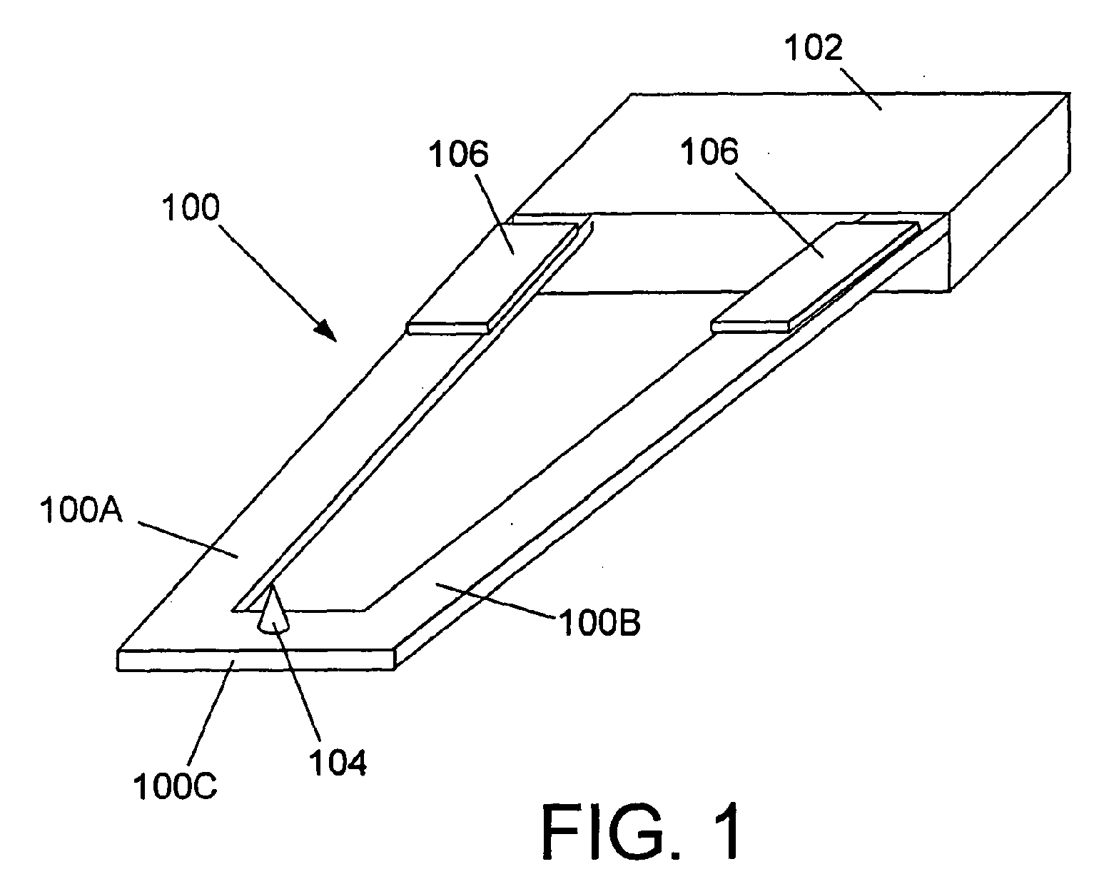
- Fig. 1 is a schematic perspective view of a cantilever (media facing side up) which has a probe and to which embodiments of the invention are applicable.
- Figs. 2A and 2B are respectively schematic side views showing the cantilever disposed with a medium in which data bits have been written by a heater which is incorporated into the embodiments of the invention, and the change in distance which is induced when a probe on the cantilever engages a flat surface of the substrate/enters or locates a data indicative topographical change.
- Fig. 3 is a schematic probe-side plan view of the cantilever showing a heater/FET arrangement according to a first embodiment of the invention
- Fig. 4 is an schematic underside plan view of the cantilever showing a heater/FET arrangement according to a second embodiment of the invention
- Fig. 5 is an schematic underside plan view of the cantilever showing a heater/FET arrangement according to a third embodiment of the invention
- Fig. 6 is an schematic underside plan view of the cantilever showing a heater/FET arrangement according to a fourth embodiment of the invention.
- Fig. 7 is circuit diagram showing the basic connection between the heater and the FET which is used in the embodiments of the invention.
- Figs. 1, 2A and 2B show a cantilever arrangement of the type to which the embodiments of the invention can be applied.
- the cantilever 100 is supported at its inboard end on a base member 102 and is formed at its outboard end with a probe 104.
- the cantilever 100 comprises two arms 100A, 100B the outboard ends of which are interconnected by an end bridge member 100C.
- the probe 104 is formed on the end bridge member 100C.
- the probe 104 is formed using suitable masking and etching or the like type of fabrication technique can be formed so as to be at least in part electrically non-conductive.
- Layers of activation material 106 are disposed on the arms of the cantilever 100 to control the flexure of the cantilever toward a medium 108 which is movable with respect to the cantilever 100 or vice versa.
- the activation material 106 is not limited to the use of intrinsically stressed material and can be alternatively formed of a piezoelectric material if so desired.
- the medium 108 is comprised of a layer of heat deformable material such as polycarbonate or polymethylmethacrylate (PMMA) for example, which is formed over the surface of a suitable support substrate.
- the medium 108 which in this case is non-conductive, can be heated locally to write data by fusing and changing the medium topography to the degree that the changes can be detected using the probe 104 in the manner depicted in Figs. 2A and 2B.
- the medium 108 is supported on a substrate 110 which in this instance is electrically conductive and is electrically connected to a sensor circuit 112 which is adapted to apply a bias to the substrate 110 and produce an electric field which can be used to gate a FET.
- topography is shown as comprising a series of data recesses or pits 108A, these can be replaced with humps (not shown) or a combination of pits and humps. It should be noted that the formation of pits may also form associated bumps in the process. Bumps will typically be formed as the regions where no pits are present.
- the cantilever can be moved toward the medium.
- a pit 108A (or isolated hump) is located under the probe 104 in the manner schematically depicted in Fig. 2A
- the entry of the probe 104 into the pit indicates the presence of a data bit.
- an absence of a data bit is indicated.
- bits may be coded such that a particular change from one state (pit, hump or flat surface) to another state would indicate a bit and other states or changes would indicate the lack of a bit.
- the invention can use other coding techniques employed in contact storage device detection patterns or other responses that are predominant in the response of the sensor-media systems.
- the topography of the medium 108 is thus such that the distance or gap between the medium 108 and a cantilever 100 on which the probe 104 is formed, varies.
- This distance variation allows a FET (field effect transistor) which is formed in the cantilever 100 proximate the probe 104 and which is generally denoted by the numeral 114 in this embodiment of the invention, to respond to changes in the electric field which is generated between the substrate 110 and the cantilever 100 and thus modulate a signal in the form of a current which passes through the FET 114 in accordance with the amount of clearance between the medium 108 and the cantilever 100.
- FET field effect transistor
- the sensor circuit 112 is also arranged to be responsive to the change in current passing through the FET 114 and thus detect the change in distance between the cantilever 100 and the substrate 110.
- a heater 116 is circuited with the FET 114 and is arranged to be supplied power via conductive traces or lines which are formed in the cantilever 100 such as by doping (ion implantation or the like) and which are common to both the heater 116 and the FET 114.
- FIG. 3 A first embodiment of the invention is schematically illustrated in Fig. 3. It should be noted however, that the portion of the cantilever 100 which is depicted in Figs. 3 - 6, is merely an end portion of the cantilever 100 that is able to move toward and away from the medium 108. As shown, the heater 116 is formed as an electrically conductive region having a suitable resistance, in a portion of the cantilever 100 which is located immediately proximate the probe 104.
- the resistance of the heater 116 can be controlled by controlling the doping concentration with respect to that of the traces on either side which are more heavily doped and thus more conductive.
- the probe 104 itself can form part of the heater to facilitate localized heating and fusing of the medium 108.
- the cantilever 100 in this embodiment, is formed of silicon which has been masked, etched and doped in a known manner to produce the illustrated configuration and electrically conductive lines or traces 114A, 114B, 114C and 114D. These traces define the source, drain and channel of the FET 114 as well as the circuit via which the heater 116 is operated.
- the heater 116 can also be used to heat and induce softening and reflow of localized areas of the medium to smooth out and erase a data indicative recess or hump. Needless to say, the heater must be maintained in proximity to this portion of the medium but with the probe 104 out of contact therewith.
- the change in distance between the portion of the cantilever 100 in which the FET 114 is formed and the medium which occurs in the manner depicted in Figs. 2A and 2B, is sufficient to change the electrical field strength in the channel region of the FET. This induces the situation wherein the change in proximity of the cantilever 100 to the substrate 108 varies the gating of the FET 114 and modulates the current which is permitted to flow from the drain 114A to the source 114B and 114D through the channel 114C which is interposed between the two.
- the FET 114 is formed only long the lower portions of the cantilever 100 and is formed only in the portions of the cantilever 100 that actually move in response to the probe encountering a topographical change.
- the formation of the FET 114 on the lower surface of the cantilever facilitates production, provides a greater W/L ratio, and a greater sensor area and gain.
- the formation of the FET 114 on portions of the cantilever which do not undergo much movement are avoided to avoid contribution to DC current and noise.
- the modulation of the current passing through the FET 114 is due solely to the changes in the electrical field which are produced between the cantilever 100 and the substrate 110 which of course must be sufficiently conductive to allow for the required electrical field to be established.
- trace 114A which extends continuously along both legs 100A, 100B and across the end bridge 100C, acts as a common drain while traces 114B and 114D act as sources for what is essentially two halves of the FET.
- Features 114C is in this embodiment, form channels which separate the drains and sources of the FET arrangement.
- the bias applied to the substrate 110 gates the FET allowing current to pass through the two channel portions 114C which are formed. Current flow between the common drain and the two source halves is used to derive a read signal. Since traces 114B and 114D are both used as "sources" during this time, no current flow through the heater 116 occurs.
- the bias to the substrate 110 is lowered to the point where gating of the FET does not occur.
- the roles of traces 114B and 114D are changed so that one acts as positive terminal for the heater 116 while the other acts as thenegative terminal. Electrical current therefore induced to passed through the heater 116.
- the FET 114 shown in Fig. 3 is a depletion mode N-channel type FET. However, the embodiment is not limited to this type of FET and may be replaced with a P-channel type if desired.
- the channel is formed by doping in the channel region. The FET will conduct in varying amounts as modulated by the gate voltage. If the gate voltage is made negative enough, the carriers will be driven from the channel causing the FET to cease to conduct.
- the medium 108 and the cantilever 100 are operatively (mechanically) interconnected so that medium 108 is selectively movable with respect to the cantilever 100 by way of a drive mechanism denoted by element 118 (schematically depicted in Fig. 2).
- This mechanism is arranged to move the two elements (viz., the cantilever 100 and the medium 108) with respect to one another so as to assume a selected coordinate relationship and position the probe 104 so that it can detect if a data indicative change in topography (e.g. a pit 108A ) is present or absent at that set of coordinates.
- a good sensor bandwidth can be expected inasmuch as the electric field responds as fast as the cantilever can move.
- the FET is thus able to respond quickly to the variations in field strength and has the potential to make the mechanics of the cantilever the limiting factor in the bandwidth.
- the signal to noise ratio (SNR) for this arrangement can be expected to be improve as compared to the above-mentioned thermal type sensor in that, with the latter, much of the useful signal is filtered out by the thermal lowpass function.
- the sensing aspect of the embodiments can be expected to produces a relatively large output signal with respect to the various noise sources and thus reduce signal degradation due to these noises.
- Fig. 3 has been disclosed as being including a depletion mode FET, it is possible, in this and the other embodiments of the invention, to use an induced-channel type FET.
- This induced-channel or enhancement mode FET is such that there is no intrinsic channel and the drain to source conductance is very low until the gate voltage is applied. When the gate voltage exceeds a given threshold, enough carriers are pulled into the channel region that the device starts to conduct.
- the channel is p-type material that forms a conduction band when sufficiently positive gate voltage is applied. When conducting, the channel behaves like n-type material.
- Fig, 4 shows a second embodiment of the invention.
- the doped traces which form left and right hand side portions of the FET 214 are simplified. This configuration allows the end bridge 200C of the cantilever 200 to be narrowed and to add a minimum of thermal mass to the area of the cantilever 200 proximate the probe 204. It also limits the thermal conductivity out into the legs of the cantilever.
- the outboard traces both act as drains for the FET 214 while the inboard traces act as sources during the read mode and are switched in the same manner as disclosed in connection with the first embodiment shown in Fig. 3.
- Fig. 5 shows a third embodiment of the invention.
- the FET 314' also acts as the heater during the heating mode and is such that the geometry of the FET elements maximizes the width of the FET in the vicinity of the probe 104.
- This embodiment accordingly has only one source 314B and one drain 314A.
- the switching between the reading and writing mode is achieved one by operating the source and drain at voltages such that the FET was turned on partially. This places the channel in a state of medium conductivity where there would be a lot of voltage drop across it. Assuming that the substrate potential was fixed, the source voltage could be set to a value to establish the "on resistance" of the FET and the drain could be set to a voltage to cause the desired amount of power to be dissipated.
- the power density in the channel may tend to be too high and the control of the FET may require accurately controlled voltages and the like.
- Fig. 6 shows a fourth embodiment of the invention.
- the cantilever 400 includes two bridge portions 400C and 400D.
- the second bridge portion 400D is formed inboard of the end bridge on which the probe and heater are formed.
- the FET 414 is formed on the second bridge and thus isolated from the heater 416.
- the FET 414 is formed so as to have interdigitized source and drain portions 414S, 414D with channels 414C interposed therebetween in the illustrated manner.
- This interdigitzing or interlacing of the FET source and drain structures provides a higher W/L ratio and thus improves performance.
- This embodiment of course requires the structure of the cantilever to be modified. However, this modification is readily achieved using conventional etching techniques and as such no further disclosure of this is deemed necessary.
- Fig. 7 shows, in circuit diagram form, the arrangement which is established in Fig. 6.
- the bias which is applied to the substrate 110 gates the FET structure 414 which is formed in the second bridge portion 400D of the cantilever 400.
- the bias applied to the substrate 110 can be adjusted to a level where the FET 414 is rendered non-conductive and exhibits (by way of example) a resistance of more than 10,000 ⁇ . This enables sufficient current to be supplied to the heater 416 via the legs 414A1 and 414A2, to elevate the temperature of the portion of the cantilever surrounding (and/or including) the probe 404, sufficiently to fuse and modify the topography of the medium 108 should the probe be induced to press down against the surface of the medium 108.
- the bias to the substrate 110 is elevated to level wherein the FET can be gated and thus rendered conductive (thus exhibiting a resistance of 1000 ⁇ for example).
- the high resistance of the heater e.g. about 3500 ⁇
- ARS Atomic Resolution Storage
- CPS Contact Probe Storage
Abstract
Description
- The present invention relates to a read/write arrangement for Contact Probe Storage (CPS) arrangements and the like, wherein a heater is used to heat a medium and modify its topography so that data bits are written thereinto, and wherein a read sensor arrangement, which is based on a FET (Field Effect Transistor), responds to changes in distance from a substrate that supports the medium and emits an electric field, induced by the modified topography.
- It has been hitherto been proposed to sense data which is written onto a movable medium using a probe that is supported on a cantilever and used to contact movable the medium. A heated element (heater) is provided in the cantilever proximate the probe. The heater is heated by passing a current of electricity therethrough. By using heat transfer characteristics between the movable medium and the probe (or a portion of the cantilever in which the heating element is formed), it is possible to determine minute changes in distance between the movable medium and the cantilever on which the probe is carried, and to use this as a means for reading out the data stored on the movable medium.
- The heater in the cantilever can be used for both reading and writing. The reading function uses a thermal readback sensor arrangement which exploits a temperature-dependent resistance function. In this arrangement, the resistance (R) increases nonlinearly with heating power/temperature from room temperature to a peak value of 500 - 700°C (writing). The peak temperature is determined by the doping concentration in the heater platform, which ranges from 1 x 10¹⁷ to 2 x 10¹⁸. Above the peak temperature, the resistance drops as the number of intrinsic carriers increases because of thermal excitation.
- During sensing, the resistor is operated at about 200°C. This temperature is not high enough to soften the polymer medium, as is necessary for writing, but allows molecular energy transfer between the cantilever on which the probe is carried, and the moving medium, to remove heat and thus provide a parameter which allows the distance between the cantilever on which the probe is carried and the medium on which the probe is running to be measured.
- That is to say, this thermal sensing is based on the fact that the thermal conductance between the heater platform and the storage substrate changes according to the distance between them. The medium between a cantilever and the storage substrate, in this case air, transports heat from from one side the heater/cantilever to the other of storage media/substrate. When the distance between heater and media is reduced as the probe moves into a bit indentation, heat is more efficiently transported through the air and the heaters temperature and hence its resistance decreases. Thus, changes in temperature of the continuously heated resistor are monitored while the cantilever is scanned over data bits, providing a means of detecting the bits.
- Under typical operating conditions, the sensitivity of the thermomechanical sensing is even better than that of piezoresistive-strain sensing inasmuch as thermal effects in semiconductors are stronger than strain effects. A ΔR/R sensitivity of about 10-4 /nm is demonstrated by the images of the 40-nm-size bit indentations. This is better than the results are obtained using the piezoresistive-strain technique.
- Nevertheless, the thermal response has been found to be slower than desired and is significantly slower than the cantilever's ability to mechanically follow the data pattern written in the medium. This leads to the system's read performance being slower than it would be if it were not limited to the thermal response of the sensing system.
- Fig. 1 is a schematic perspective view of a cantilever (media facing side up) which has a probe and to which embodiments of the invention are applicable.
- Figs. 2A and 2B are respectively schematic side views showing the cantilever disposed with a medium in which data bits have been written by a heater which is incorporated into the embodiments of the invention, and the change in distance which is induced when a probe on the cantilever engages a flat surface of the substrate/enters or locates a data indicative topographical change.
- Fig. 3 is a schematic probe-side plan view of the cantilever showing a heater/FET arrangement according to a first embodiment of the invention
- Fig. 4 is an schematic underside plan view of the cantilever showing a heater/FET arrangement according to a second embodiment of the invention
- Fig. 5 is an schematic underside plan view of the cantilever showing a heater/FET arrangement according to a third embodiment of the invention
- Fig. 6 is an schematic underside plan view of the cantilever showing a heater/FET arrangement according to a fourth embodiment of the invention.
- Fig. 7 is circuit diagram showing the basic connection between the heater and the FET which is used in the embodiments of the invention.
- Figs. 1, 2A and 2B show a cantilever arrangement of the type to which the embodiments of the invention can be applied. The
cantilever 100 is supported at its inboard end on abase member 102 and is formed at its outboard end with aprobe 104. In the illustrated arrangement, thecantilever 100 comprises twoarms end bridge member 100C. - The
probe 104 is formed on theend bridge member 100C. Theprobe 104 is formed using suitable masking and etching or the like type of fabrication technique can be formed so as to be at least in part electrically non-conductive. - Layers of
activation material 106 are disposed on the arms of thecantilever 100 to control the flexure of the cantilever toward amedium 108 which is movable with respect to thecantilever 100 or vice versa. Theactivation material 106, however, is not limited to the use of intrinsically stressed material and can be alternatively formed of a piezoelectric material if so desired. - The
medium 108 is comprised of a layer of heat deformable material such as polycarbonate or polymethylmethacrylate (PMMA) for example, which is formed over the surface of a suitable support substrate. Themedium 108, which in this case is non-conductive, can be heated locally to write data by fusing and changing the medium topography to the degree that the changes can be detected using theprobe 104 in the manner depicted in Figs. 2A and 2B. Themedium 108 is supported on asubstrate 110 which in this instance is electrically conductive and is electrically connected to asensor circuit 112 which is adapted to apply a bias to thesubstrate 110 and produce an electric field which can be used to gate a FET. - Although the topography is shown as comprising a series of data recesses or
pits 108A, these can be replaced with humps (not shown) or a combination of pits and humps. It should be noted that the formation of pits may also form associated bumps in the process. Bumps will typically be formed as the regions where no pits are present. - Thus, when the
medium 108 or thecantilever 100 has been moved relative to the other to assume an exact coordinate relationship, the cantilever can be moved toward the medium. In the event that apit 108A (or isolated hump) is located under theprobe 104 in the manner schematically depicted in Fig. 2A, the entry of theprobe 104 into the pit (or engagement with the top of the hump) indicates the presence of a data bit. Should theprobe 104 not find a pit or a hump and seat on the flat surface of the medium such as depicted in Fig. 2A then an absence of a data bit is indicated. - Additionally, the bits may be coded such that a particular change from one state (pit, hump or flat surface) to another state would indicate a bit and other states or changes would indicate the lack of a bit. The invention can use other coding techniques employed in contact storage device detection patterns or other responses that are predominant in the response of the sensor-media systems.
- The topography of the
medium 108 is thus such that the distance or gap between themedium 108 and acantilever 100 on which theprobe 104 is formed, varies. This distance variation allows a FET (field effect transistor) which is formed in thecantilever 100 proximate theprobe 104 and which is generally denoted by thenumeral 114 in this embodiment of the invention, to respond to changes in the electric field which is generated between thesubstrate 110 and thecantilever 100 and thus modulate a signal in the form of a current which passes through theFET 114 in accordance with the amount of clearance between themedium 108 and thecantilever 100. - The
sensor circuit 112 is also arranged to be responsive to the change in current passing through theFET 114 and thus detect the change in distance between thecantilever 100 and thesubstrate 110. In the embodiments of the invention, aheater 116 is circuited with theFET 114 and is arranged to be supplied power via conductive traces or lines which are formed in thecantilever 100 such as by doping (ion implantation or the like) and which are common to both theheater 116 and the FET 114. - A first embodiment of the invention is schematically illustrated in Fig. 3. It should be noted however, that the portion of the
cantilever 100 which is depicted in Figs. 3 - 6, is merely an end portion of thecantilever 100 that is able to move toward and away from themedium 108. As shown, theheater 116 is formed as an electrically conductive region having a suitable resistance, in a portion of thecantilever 100 which is located immediately proximate theprobe 104. - The resistance of the
heater 116 can be controlled by controlling the doping concentration with respect to that of the traces on either side which are more heavily doped and thus more conductive. As will be appreciated, theprobe 104 itself can form part of the heater to facilitate localized heating and fusing of themedium 108. - The
cantilever 100, in this embodiment, is formed of silicon which has been masked, etched and doped in a known manner to produce the illustrated configuration and electrically conductive lines or traces 114A, 114B, 114C and 114D. These traces define the source, drain and channel of the FET 114 as well as the circuit via which theheater 116 is operated. - In addition to writing, the
heater 116 can also be used to heat and induce softening and reflow of localized areas of the medium to smooth out and erase a data indicative recess or hump. Needless to say, the heater must be maintained in proximity to this portion of the medium but with theprobe 104 out of contact therewith. - The change in distance between the portion of the
cantilever 100 in which theFET 114 is formed and the medium which occurs in the manner depicted in Figs. 2A and 2B, is sufficient to change the electrical field strength in the channel region of the FET. This induces the situation wherein the change in proximity of thecantilever 100 to thesubstrate 108 varies the gating of theFET 114 and modulates the current which is permitted to flow from thedrain 114A to thesource 114B and 114D through thechannel 114C which is interposed between the two. - The
FET 114 is formed only long the lower portions of thecantilever 100 and is formed only in the portions of thecantilever 100 that actually move in response to the probe encountering a topographical change. The formation of theFET 114 on the lower surface of the cantilever facilitates production, provides a greater W/L ratio, and a greater sensor area and gain. The formation of theFET 114 on portions of the cantilever which do not undergo much movement are avoided to avoid contribution to DC current and noise. - Since the
probe 104 moves over/contacts an electricallynon-conductive medium 108, the modulation of the current passing through theFET 114 is due solely to the changes in the electrical field which are produced between thecantilever 100 and thesubstrate 110 which of course must be sufficiently conductive to allow for the required electrical field to be established. - During the read mode of operation, trace 114A, which extends continuously along both
legs end bridge 100C, acts as a common drain whiletraces 114B and 114D act as sources for what is essentially two halves of the FET.Features 114C, is in this embodiment, form channels which separate the drains and sources of the FET arrangement. - The bias applied to the
substrate 110 gates the FET allowing current to pass through the twochannel portions 114C which are formed. Current flow between the common drain and the two source halves is used to derive a read signal. Sincetraces 114B and 114D are both used as "sources" during this time, no current flow through theheater 116 occurs. - During the heating/write mode of operation, the bias to the
substrate 110 is lowered to the point where gating of the FET does not occur. At this time the roles oftraces 114B and 114D are changed so that one acts as positive terminal for theheater 116 while the other acts as thenegative terminal. Electrical current therefore induced to passed through theheater 116. - The switching arrangement which allows this change between read and write modes of operation is well within the purview of the person of skill in the art of electrical controls and thus no further discussion will be given for the sake of brevity.
- The
FET 114 shown in Fig. 3 is a depletion mode N-channel type FET. However, the embodiment is not limited to this type of FET and may be replaced with a P-channel type if desired. In depletion mode FETs, the channel is formed by doping in the channel region. The FET will conduct in varying amounts as modulated by the gate voltage. If the gate voltage is made negative enough, the carriers will be driven from the channel causing the FET to cease to conduct. - As shown in Figs. 2A and 2B the medium 108 and the
cantilever 100 are operatively (mechanically) interconnected so that medium 108 is selectively movable with respect to thecantilever 100 by way of a drive mechanism denoted by element 118 (schematically depicted in Fig. 2). This mechanism is arranged to move the two elements (viz., thecantilever 100 and the medium 108) with respect to one another so as to assume a selected coordinate relationship and position theprobe 104 so that it can detect if a data indicative change in topography (e.g. apit 108A ) is present or absent at that set of coordinates. - With this embodiment, a good sensor bandwidth can be expected inasmuch as the electric field responds as fast as the cantilever can move. The FET is thus able to respond quickly to the variations in field strength and has the potential to make the mechanics of the cantilever the limiting factor in the bandwidth. The signal to noise ratio (SNR) for this arrangement can be expected to be improve as compared to the above-mentioned thermal type sensor in that, with the latter, much of the useful signal is filtered out by the thermal lowpass function.
- Since the FET is capable of producing gain, the sensing aspect of the embodiments can be expected to produces a relatively large output signal with respect to the various noise sources and thus reduce signal degradation due to these noises.
- While the embodiment of Fig. 3 has been disclosed as being including a depletion mode FET, it is possible, in this and the other embodiments of the invention, to use an induced-channel type FET. This induced-channel or enhancement mode FET is such that there is no intrinsic channel and the drain to source conductance is very low until the gate voltage is applied. When the gate voltage exceeds a given threshold, enough carriers are pulled into the channel region that the device starts to conduct. In an N-channel enhancement type FET, the channel is p-type material that forms a conduction band when sufficiently positive gate voltage is applied. When conducting, the channel behaves like n-type material.
- Fig, 4 shows a second embodiment of the invention. In this embodiment the doped traces which form left and right hand side portions of the
FET 214 are simplified. This configuration allows theend bridge 200C of the cantilever 200 to be narrowed and to add a minimum of thermal mass to the area of the cantilever 200 proximate theprobe 204. It also limits the thermal conductivity out into the legs of the cantilever. - With the
heater 216 interposed in the illustrated manner, the outboard traces both act as drains for theFET 214 while the inboard traces act as sources during the read mode and are switched in the same manner as disclosed in connection with the first embodiment shown in Fig. 3. - Fig. 5 shows a third embodiment of the invention. In this embodiment the FET 314' also acts as the heater during the heating mode and is such that the geometry of the FET elements maximizes the width of the FET in the vicinity of the
probe 104. This embodiment accordingly has only onesource 314B and onedrain 314A. - The switching between the reading and writing mode is achieved one by operating the source and drain at voltages such that the FET was turned on partially. This places the channel in a state of medium conductivity where there would be a lot of voltage drop across it. Assuming that the substrate potential was fixed, the source voltage could be set to a value to establish the "on resistance" of the FET and the drain could be set to a voltage to cause the desired amount of power to be dissipated.
- With this technique however, the power density in the channel may tend to be too high and the control of the FET may require accurately controlled voltages and the like.
- Fig. 6 shows a fourth embodiment of the invention. In this embodiment the cantilever 400 includes two
bridge portions second bridge portion 400D is formed inboard of the end bridge on which the probe and heater are formed. TheFET 414 is formed on the second bridge and thus isolated from theheater 416. TheFET 414 is formed so as to have interdigitized source and drain portions 414S, 414D withchannels 414C interposed therebetween in the illustrated manner. This interdigitzing or interlacing of the FET source and drain structures provides a higher W/L ratio and thus improves performance. This embodiment of course requires the structure of the cantilever to be modified. However, this modification is readily achieved using conventional etching techniques and as such no further disclosure of this is deemed necessary. - Fig. 7 shows, in circuit diagram form, the arrangement which is established in Fig. 6. As will be appreciated from this diagram, the bias which is applied to the
substrate 110 gates theFET structure 414 which is formed in thesecond bridge portion 400D of the cantilever 400. During the writing phase, the bias applied to thesubstrate 110 can be adjusted to a level where theFET 414 is rendered non-conductive and exhibits (by way of example) a resistance of more than 10,000Ω. This enables sufficient current to be supplied to theheater 416 via the legs 414A1 and 414A2, to elevate the temperature of the portion of the cantilever surrounding (and/or including) theprobe 404, sufficiently to fuse and modify the topography of the medium 108 should the probe be induced to press down against the surface of the medium 108. - Conversely, during the sensing phase, the bias to the
substrate 110 is elevated to level wherein the FET can be gated and thus rendered conductive (thus exhibiting a resistance of 1000Ω for example). During this time, the high resistance of the heater (e.g. about 3500Ω) effectively directs a majority of the current flow through theFET 414 and the temperature of the heater falls to essentially ambient levels. - Although the invention has been disclosed with reference to a limited number of embodiments, the various modifications and variations which can be made without departing from the scope of the invention, which is limited only by the appended claims, will be self-evident to those skilled in the art of Atomic Resolution Storage (ARS) and Contact Probe Storage (CPS) technology. For example, while the second - fourth embodiments shown in Figs. 4-6, are shown using depletion mode FETs, they may be adapted to be induced-channel or enhancement mode FETs.
Claims (10)
- A read/write arrangement comprising:a cantilever (100, 200, 300, 400) disposed with a medium (108) which is movable relative to the cantilever;a device (114, 214, 314', 414) associated with one of the cantilever and the medium which is configured to be responsive to changes in electrical field between the medium and the cantilever caused by a change in distance between the medium and the cantilever;a heater (116, 216, 314', 316), disposed on the cantilever for heating the medium and for inducing localized topographical changes which represent bits of data; anda circuit (114A,B,C; 214A,B,C; 314A,B,C; 414A,B,C) which electrically interconnects both of the device and the heater.
- A read/write arrangement as set forth in claim 1, wherein the circuit (114A,B,C; 214A,B,C; 314A,B,C; 414A,B,C) forms at least a part of one of the device.
- A read/write arrangement as set forth in claim 1, wherein the circuit (114A,B,C; 214A,B,C; 314A,B,C; 414A,B,C) has portions which are common to both the device and the heater.
- A read/write arrangement as set forth in claim 1, wherein the cantilever (100, 200, 300, 400) comprises a probe (104, 204, 304, 404) which extends from the cantilever and which is configured to be contactable with a surface of the medium (108) and to respond to a topography of the medium to cause the distance between the cantilever (100, 200, 300, 400) and the medium (108) to vary.
- A read/write arrangement as set forth in claim 1, wherein the device is a FET (Field Effect Transistor).
- A read/write arrangement for a contact probe atomic resolution storage system, comprising:a cantilever (100, 200, 300, 400) disposed with an electrically non-conductive medium (108) which is movable relative to the cantilever, the cantilever having a probe (104, 204, 304, 404) which is configured to follow a topography of the medium;a device (114, 214, 314', 414) formed in the cantilever which responds to a change in electric field induced by a change in distance between the cantilever and a substrate on which the medium is supported; anda heater (116, 216, 314', 416) disposed in the cantilever and circuited with the device.
- A read/write mechanism as set forth in claim 6, wherein the device is a FET (Field Effect Transistor).
- A method of making a read/write arrangement comprising:forming a FET (114, 214, 314', 414) in a silicon cantilever (100, 200, 300, 400) by doping electrically conductive source and drain regions 114A,B; 214A,B; 314A,B; 414A,B) in a selected surface of the cantilever, the FET being configured to be gated by an electric field which is generated by applying a bias to a substrate separate from the cantilever;forming a probe (104,204,304,404) on the selected surface of the cantilever; andforming a heater (116, 216, 314', 316) in the cantilever proximate the probe.
- A method as set forth in claim 8, further comprising:forming the cantilever (100, 200, 300, 400) to have arms 100A,B; 200A, B; 300A, B; 400A,B) and an end bridge portion (100C, 200C, 300C, 400C) which interconnects terminal outboard ends of the arms; andforming the probe (104,204,304,404) and the heater (116, 216, 314', 316) on the end bridge portion (100C, 200C, 300C, 400C) .
- A read/write arrangement comprising:FET means (114, 214, 314', 414) formed in a silicon cantilever (100, 200, 300, 400) by doping electrically conductive source and drain regions in a selected surface of the cantilever, for being gated by an electric field which is generated by applying a bias to a substrate separate from the cantilever;a probe (104,204,304,404) on the selected surface of the cantilever; andheater means (116, 216, 314', 316) in the cantilever proximate the probe for heating and forming a data bit indicative topography in a medium to be engaged by the probe.
Applications Claiming Priority (2)
| Application Number | Priority Date | Filing Date | Title |
|---|---|---|---|
| US736600 | 2003-12-17 | ||
| US10/736,600 US7460462B2 (en) | 2003-12-17 | 2003-12-17 | Contact probe storage fet sensor and write heater arrangements |
Publications (1)
| Publication Number | Publication Date |
|---|---|
| EP1544858A1 true EP1544858A1 (en) | 2005-06-22 |
Family
ID=34523124
Family Applications (1)
| Application Number | Title | Priority Date | Filing Date |
|---|---|---|---|
| EP04015145A Withdrawn EP1544858A1 (en) | 2003-12-17 | 2004-06-28 | Contact probe storage fet sensor and write heater arrangements |
Country Status (3)
| Country | Link |
|---|---|
| US (2) | US7460462B2 (en) |
| EP (1) | EP1544858A1 (en) |
| CN (1) | CN1629958A (en) |
Cited By (1)
| Publication number | Priority date | Publication date | Assignee | Title |
|---|---|---|---|---|
| EP1544859A1 (en) * | 2003-12-17 | 2005-06-22 | Hewlett-Packard Development Company, L.P. | Read/write arrangements for probes |
Families Citing this family (25)
| Publication number | Priority date | Publication date | Assignee | Title |
|---|---|---|---|---|
| US7233517B2 (en) * | 2002-10-15 | 2007-06-19 | Nanochip, Inc. | Atomic probes and media for high density data storage |
| CA2552958A1 (en) * | 2003-12-09 | 2005-06-23 | Wriota Pty Ltd | A memory device, an information storage process, a process, and a structured material |
| US7436753B2 (en) * | 2003-12-17 | 2008-10-14 | Mejia Robert G | Contact probe storage FET sensor |
| KR100595523B1 (en) * | 2004-07-20 | 2006-07-03 | 엘지전자 주식회사 | Nano data writing and reading apparatus using cantilever transfer and manufacturing method thereof |
| US20070041237A1 (en) * | 2005-07-08 | 2007-02-22 | Nanochip, Inc. | Media for writing highly resolved domains |
| KR100849391B1 (en) | 2005-07-14 | 2008-07-31 | 전자부품연구원 | Atomic force microscopy cantilever to possible reading/wrighting |
| CN1967687B (en) * | 2005-11-17 | 2011-01-26 | Lg电子株式会社 | Read-in and read device of millimicro data using cantilever structure and its manufacturing method |
| US8018818B2 (en) * | 2006-03-30 | 2011-09-13 | International Business Machines Corporation | Systems and methods for storing and reading data in a data storage system |
| US8374071B2 (en) * | 2007-05-23 | 2013-02-12 | International Business Machines Corporation | Data storage device |
| KR101162729B1 (en) * | 2007-07-30 | 2012-07-05 | 삼성전자주식회사 | Method improving sensitivity of electric field detecting sensor, storage apparatus adopting electric field detecting sensor, and reading method thereof |
| TWI615337B (en) | 2009-04-10 | 2018-02-21 | 辛波提克有限責任公司 | Automated case unit storage system and method for handling case units that are configured for being arrayed into a palletized load of case units for shipping to or from a storage facility |
| US20110041224A1 (en) * | 2009-08-06 | 2011-02-17 | Purdue Research Foundation | Atomic force microscope including accelerometer |
| JP2012022537A (en) * | 2010-07-15 | 2012-02-02 | Hitachi Ltd | Piezoelectric actuator drive unit |
| US10822168B2 (en) | 2010-12-15 | 2020-11-03 | Symbotic Llc | Warehousing scalable storage structure |
| US9008884B2 (en) | 2010-12-15 | 2015-04-14 | Symbotic Llc | Bot position sensing |
| US20120191517A1 (en) | 2010-12-15 | 2012-07-26 | Daffin Jr Mack Paul | Prepaid virtual card |
| US9475649B2 (en) | 2010-12-15 | 2016-10-25 | Symbolic, LLC | Pickface builder for storage and retrieval systems |
| US8998554B2 (en) | 2010-12-15 | 2015-04-07 | Symbotic Llc | Multilevel vertical conveyor platform guides |
| TWI622540B (en) | 2011-09-09 | 2018-05-01 | 辛波提克有限責任公司 | Automated storage and retrieval system |
| US10834820B2 (en) | 2013-08-06 | 2020-11-10 | Bedrock Automation Platforms Inc. | Industrial control system cable |
| US11565598B2 (en) | 2013-03-15 | 2023-01-31 | Symbotic Llc | Rover charging system with one or more charging stations configured to control an output of the charging station independent of a charging station status |
| US9481517B2 (en) | 2013-03-15 | 2016-11-01 | Symbotic, LLC | Multiposition lift |
| TWI594933B (en) | 2013-03-15 | 2017-08-11 | 辛波提克有限責任公司 | Automated storage and retrieval system |
| CN105705441B (en) | 2013-09-13 | 2018-04-10 | 西姆伯蒂克有限责任公司 | Autonomous transport car, the method for storing and fetching system and selection face being transmitted in the system |
| CN106018566B (en) * | 2016-07-05 | 2018-07-13 | 华中科技大学 | A kind of ultrasonic transduction device |
Citations (9)
| Publication number | Priority date | Publication date | Assignee | Title |
|---|---|---|---|---|
| US3920930A (en) * | 1974-04-08 | 1975-11-18 | John James Sobczyk | Field effect recordings and semiconductor playback devices |
| US5323377A (en) * | 1992-11-27 | 1994-06-21 | Chen Zhi Q | Electrical data recording and retrieval based on impedance variation |
| US6101164A (en) * | 1994-01-31 | 2000-08-08 | Matsushita Electric Industrial Co., Ltd. | High density recording by a conductive probe contact with phase change recording layer |
| US20020008304A1 (en) * | 1999-11-09 | 2002-01-24 | Gunbae Lim | Scanning probe microscope (SPM) probe having field effect transistor channel and method of fabricating the same |
| WO2002037488A1 (en) * | 2000-11-03 | 2002-05-10 | International Business Machines Corporation | Afm-based data storage and microscopy |
| US20020066855A1 (en) * | 2000-12-01 | 2002-06-06 | Choi Jae-Joon | Apparatus for recording and reading data and method of recording and reading data using contact resistance measurement thereof |
| US6477132B1 (en) * | 1998-08-19 | 2002-11-05 | Canon Kabushiki Kaisha | Probe and information recording/reproduction apparatus using the same |
| WO2003042627A2 (en) * | 2001-11-14 | 2003-05-22 | Universität Kassel | Field effect transistor sensor for a screen probe microscope |
| EP1544859A1 (en) * | 2003-12-17 | 2005-06-22 | Hewlett-Packard Development Company, L.P. | Read/write arrangements for probes |
Family Cites Families (11)
| Publication number | Priority date | Publication date | Assignee | Title |
|---|---|---|---|---|
| JPH10506457A (en) | 1994-07-28 | 1998-06-23 | ジェネラル ナノテクノロジー エルエルシー | Scanning probe microscope equipment |
| US6079255A (en) * | 1996-03-13 | 2000-06-27 | International Business Machines Corporation | Mechanically coupled alternatively usable cantilever structures for scanning a surface |
| US5835477A (en) * | 1996-07-10 | 1998-11-10 | International Business Machines Corporation | Mass-storage applications of local probe arrays |
| US5729026A (en) * | 1996-08-29 | 1998-03-17 | International Business Machines Corporation | Atomic force microscope system with angled cantilever having integral in-plane tip |
| JPH11265520A (en) * | 1998-03-17 | 1999-09-28 | Hitachi Ltd | Adjacent field optical head, working method therefor and optical recording and reproducing device |
| US6518570B1 (en) * | 1998-04-03 | 2003-02-11 | Brookhaven Science Associates | Sensing mode atomic force microscope |
| EP0990195B1 (en) * | 1998-04-28 | 2001-10-24 | Ohlsson, Olaf, Dr. | Low-cost photoplastic cantilever |
| US6615277B1 (en) * | 1999-03-29 | 2003-09-02 | International Business Machines Corporation | Cross-platform program, system, and method having a global registry object for mapping registry equivalent functions in an operating system environment |
| JP3910372B2 (en) | 2000-03-03 | 2007-04-25 | インターナショナル・ビジネス・マシーンズ・コーポレーション | Storage system and writing method |
| US6583411B1 (en) * | 2000-09-13 | 2003-06-24 | Europaisches Laboratorium Für Molekularbiologie (Embl) | Multiple local probe measuring device and method |
| US7054257B2 (en) * | 2003-04-29 | 2006-05-30 | International Business Machines Corporation | AFM-based data storage and microscopy |
-
2003
- 2003-12-17 US US10/736,600 patent/US7460462B2/en not_active Expired - Fee Related
-
2004
- 2004-04-20 US US10/827,370 patent/US7542402B2/en not_active Expired - Fee Related
- 2004-06-28 EP EP04015145A patent/EP1544858A1/en not_active Withdrawn
- 2004-12-16 CN CNA2004101020189A patent/CN1629958A/en active Pending
Patent Citations (9)
| Publication number | Priority date | Publication date | Assignee | Title |
|---|---|---|---|---|
| US3920930A (en) * | 1974-04-08 | 1975-11-18 | John James Sobczyk | Field effect recordings and semiconductor playback devices |
| US5323377A (en) * | 1992-11-27 | 1994-06-21 | Chen Zhi Q | Electrical data recording and retrieval based on impedance variation |
| US6101164A (en) * | 1994-01-31 | 2000-08-08 | Matsushita Electric Industrial Co., Ltd. | High density recording by a conductive probe contact with phase change recording layer |
| US6477132B1 (en) * | 1998-08-19 | 2002-11-05 | Canon Kabushiki Kaisha | Probe and information recording/reproduction apparatus using the same |
| US20020008304A1 (en) * | 1999-11-09 | 2002-01-24 | Gunbae Lim | Scanning probe microscope (SPM) probe having field effect transistor channel and method of fabricating the same |
| WO2002037488A1 (en) * | 2000-11-03 | 2002-05-10 | International Business Machines Corporation | Afm-based data storage and microscopy |
| US20020066855A1 (en) * | 2000-12-01 | 2002-06-06 | Choi Jae-Joon | Apparatus for recording and reading data and method of recording and reading data using contact resistance measurement thereof |
| WO2003042627A2 (en) * | 2001-11-14 | 2003-05-22 | Universität Kassel | Field effect transistor sensor for a screen probe microscope |
| EP1544859A1 (en) * | 2003-12-17 | 2005-06-22 | Hewlett-Packard Development Company, L.P. | Read/write arrangements for probes |
Cited By (1)
| Publication number | Priority date | Publication date | Assignee | Title |
|---|---|---|---|---|
| EP1544859A1 (en) * | 2003-12-17 | 2005-06-22 | Hewlett-Packard Development Company, L.P. | Read/write arrangements for probes |
Also Published As
| Publication number | Publication date |
|---|---|
| US20050135199A1 (en) | 2005-06-23 |
| US7460462B2 (en) | 2008-12-02 |
| CN1629958A (en) | 2005-06-22 |
| US7542402B2 (en) | 2009-06-02 |
| US20050135200A1 (en) | 2005-06-23 |
Similar Documents
| Publication | Publication Date | Title |
|---|---|---|
| US7460462B2 (en) | Contact probe storage fet sensor and write heater arrangements | |
| US7482826B2 (en) | Probe for scanning over a substrate and a data storage device | |
| US7787350B2 (en) | Data storage device | |
| US5796290A (en) | Temperature detection method and circuit using MOSFET | |
| US7589928B2 (en) | Magnetic recording device including a thermal proximity sensor | |
| US7212487B2 (en) | Data readout arrangement | |
| US7268348B2 (en) | Scanning probe for data storage and microscopy | |
| US7423954B2 (en) | Contact probe storage sensor pod | |
| US7436753B2 (en) | Contact probe storage FET sensor | |
| JP3801468B2 (en) | Ultra high density information storage device based on modulated cathode conductivity | |
| US7849516B2 (en) | Probe for scanning over a substrate and a data storage device | |
| US7054257B2 (en) | AFM-based data storage and microscopy | |
| EP1544859A1 (en) | Read/write arrangements for probes | |
| KR100690415B1 (en) | ???-based data storage and microscopy | |
| US20060212978A1 (en) | Apparatus and method for reading bit values using microprobe on a cantilever | |
| JPH08297870A (en) | Device and method for processing information | |
| JPH10188376A (en) | Information recording medium, reader for the medium and method for executing the device | |
| US8373431B2 (en) | Probe for scanning over a substrate and data storage device | |
| US6804137B1 (en) | Data storage medium having layers acting as transistor | |
| KR100657947B1 (en) | Electrical Read HeadProbe having high sensitivity and resolution power and method of operating the same | |
| US20050141397A1 (en) | Data storing and reading apparatus | |
| JPH117667A (en) | Device and method for recording/reproducing | |
| JPH02125759A (en) | Printing apparatus |
Legal Events
| Date | Code | Title | Description |
|---|---|---|---|
| PUAI | Public reference made under article 153(3) epc to a published international application that has entered the european phase |
Free format text: ORIGINAL CODE: 0009012 |
|
| AK | Designated contracting states |
Kind code of ref document: A1 Designated state(s): AT BE BG CH CY CZ DE DK EE ES FI FR GB GR HU IE IT LI LU MC NL PL PT RO SE SI SK TR |
|
| AX | Request for extension of the european patent |
Extension state: AL HR LT LV MK |
|
| 17P | Request for examination filed |
Effective date: 20050620 |
|
| AKX | Designation fees paid |
Designated state(s): DE GB IT |
|
| 17Q | First examination report despatched |
Effective date: 20061016 |
|
| GRAP | Despatch of communication of intention to grant a patent |
Free format text: ORIGINAL CODE: EPIDOSNIGR1 |
|
| STAA | Information on the status of an ep patent application or granted ep patent |
Free format text: STATUS: THE APPLICATION IS DEEMED TO BE WITHDRAWN |
|
| 18D | Application deemed to be withdrawn |
Effective date: 20081218 |