EP1548433A1 - Analyzing tool - Google Patents
Analyzing tool Download PDFInfo
- Publication number
- EP1548433A1 EP1548433A1 EP03798513A EP03798513A EP1548433A1 EP 1548433 A1 EP1548433 A1 EP 1548433A1 EP 03798513 A EP03798513 A EP 03798513A EP 03798513 A EP03798513 A EP 03798513A EP 1548433 A1 EP1548433 A1 EP 1548433A1
- Authority
- EP
- European Patent Office
- Prior art keywords
- liquid
- sample liquid
- flow path
- analytical tool
- tool according
- Prior art date
- Legal status (The legal status is an assumption and is not a legal conclusion. Google has not performed a legal analysis and makes no representation as to the accuracy of the status listed.)
- Granted
Links
Images


Classifications
-
- G—PHYSICS
- G01—MEASURING; TESTING
- G01N—INVESTIGATING OR ANALYSING MATERIALS BY DETERMINING THEIR CHEMICAL OR PHYSICAL PROPERTIES
- G01N21/00—Investigating or analysing materials by the use of optical means, i.e. using sub-millimetre waves, infrared, visible or ultraviolet light
- G01N21/01—Arrangements or apparatus for facilitating the optical investigation
- G01N21/03—Cuvette constructions
- G01N21/07—Centrifugal type cuvettes
-
- B—PERFORMING OPERATIONS; TRANSPORTING
- B01—PHYSICAL OR CHEMICAL PROCESSES OR APPARATUS IN GENERAL
- B01L—CHEMICAL OR PHYSICAL LABORATORY APPARATUS FOR GENERAL USE
- B01L3/00—Containers or dishes for laboratory use, e.g. laboratory glassware; Droppers
- B01L3/50—Containers for the purpose of retaining a material to be analysed, e.g. test tubes
- B01L3/502—Containers for the purpose of retaining a material to be analysed, e.g. test tubes with fluid transport, e.g. in multi-compartment structures
- B01L3/5027—Containers for the purpose of retaining a material to be analysed, e.g. test tubes with fluid transport, e.g. in multi-compartment structures by integrated microfluidic structures, i.e. dimensions of channels and chambers are such that surface tension forces are important, e.g. lab-on-a-chip
- B01L3/502753—Containers for the purpose of retaining a material to be analysed, e.g. test tubes with fluid transport, e.g. in multi-compartment structures by integrated microfluidic structures, i.e. dimensions of channels and chambers are such that surface tension forces are important, e.g. lab-on-a-chip characterised by bulk separation arrangements on lab-on-a-chip devices, e.g. for filtration or centrifugation
-
- B—PERFORMING OPERATIONS; TRANSPORTING
- B01—PHYSICAL OR CHEMICAL PROCESSES OR APPARATUS IN GENERAL
- B01L—CHEMICAL OR PHYSICAL LABORATORY APPARATUS FOR GENERAL USE
- B01L2300/00—Additional constructional details
- B01L2300/06—Auxiliary integrated devices, integrated components
- B01L2300/0681—Filter
-
- B—PERFORMING OPERATIONS; TRANSPORTING
- B01—PHYSICAL OR CHEMICAL PROCESSES OR APPARATUS IN GENERAL
- B01L—CHEMICAL OR PHYSICAL LABORATORY APPARATUS FOR GENERAL USE
- B01L2300/00—Additional constructional details
- B01L2300/08—Geometry, shape and general structure
- B01L2300/0803—Disc shape
-
- B—PERFORMING OPERATIONS; TRANSPORTING
- B01—PHYSICAL OR CHEMICAL PROCESSES OR APPARATUS IN GENERAL
- B01L—CHEMICAL OR PHYSICAL LABORATORY APPARATUS FOR GENERAL USE
- B01L2300/00—Additional constructional details
- B01L2300/08—Geometry, shape and general structure
- B01L2300/0809—Geometry, shape and general structure rectangular shaped
- B01L2300/0816—Cards, e.g. flat sample carriers usually with flow in two horizontal directions
-
- B—PERFORMING OPERATIONS; TRANSPORTING
- B01—PHYSICAL OR CHEMICAL PROCESSES OR APPARATUS IN GENERAL
- B01L—CHEMICAL OR PHYSICAL LABORATORY APPARATUS FOR GENERAL USE
- B01L2300/00—Additional constructional details
- B01L2300/08—Geometry, shape and general structure
- B01L2300/0861—Configuration of multiple channels and/or chambers in a single devices
- B01L2300/0864—Configuration of multiple channels and/or chambers in a single devices comprising only one inlet and multiple receiving wells, e.g. for separation, splitting
-
- B—PERFORMING OPERATIONS; TRANSPORTING
- B01—PHYSICAL OR CHEMICAL PROCESSES OR APPARATUS IN GENERAL
- B01L—CHEMICAL OR PHYSICAL LABORATORY APPARATUS FOR GENERAL USE
- B01L2300/00—Additional constructional details
- B01L2300/08—Geometry, shape and general structure
- B01L2300/0861—Configuration of multiple channels and/or chambers in a single devices
- B01L2300/087—Multiple sequential chambers
-
- G—PHYSICS
- G01—MEASURING; TESTING
- G01N—INVESTIGATING OR ANALYSING MATERIALS BY DETERMINING THEIR CHEMICAL OR PHYSICAL PROPERTIES
- G01N1/00—Sampling; Preparing specimens for investigation
- G01N1/28—Preparing specimens for investigation including physical details of (bio-)chemical methods covered elsewhere, e.g. G01N33/50, C12Q
- G01N1/40—Concentrating samples
- G01N1/4077—Concentrating samples by other techniques involving separation of suspended solids
-
- G—PHYSICS
- G01—MEASURING; TESTING
- G01N—INVESTIGATING OR ANALYSING MATERIALS BY DETERMINING THEIR CHEMICAL OR PHYSICAL PROPERTIES
- G01N35/00—Automatic analysis not limited to methods or materials provided for in any single one of groups G01N1/00 - G01N33/00; Handling materials therefor
- G01N35/02—Automatic analysis not limited to methods or materials provided for in any single one of groups G01N1/00 - G01N33/00; Handling materials therefor using a plurality of sample containers moved by a conveyor system past one or more treatment or analysis stations
- G01N35/025—Automatic analysis not limited to methods or materials provided for in any single one of groups G01N1/00 - G01N33/00; Handling materials therefor using a plurality of sample containers moved by a conveyor system past one or more treatment or analysis stations having a carousel or turntable for reaction cells or cuvettes
-
- G—PHYSICS
- G01—MEASURING; TESTING
- G01N—INVESTIGATING OR ANALYSING MATERIALS BY DETERMINING THEIR CHEMICAL OR PHYSICAL PROPERTIES
- G01N35/00—Automatic analysis not limited to methods or materials provided for in any single one of groups G01N1/00 - G01N33/00; Handling materials therefor
- G01N35/10—Devices for transferring samples or any liquids to, in, or from, the analysis apparatus, e.g. suction devices, injection devices
- G01N35/1065—Multiple transfer devices
Definitions
- the present invention relates to an analytical tool used for analyzing a particular component contained in a sample liquid (such as blood or urine, for example).
- a sample liquid such as blood or urine, for example.
- reaction liquid obtained upon reaction of a sample and a reagent is analyzed by an optical technique, forexample.
- an analytical tool for providing a reaction field For example, there exist analytical tools which are designed to remove solid components in the sample liquid before the sample liquid is supplied to reagent portions. Examples of such analytical tools include one shown in Figs. 13 and 14 and one shown in Figs. 15 and 16 of the present application (See JP-A 2002-508698A and JP-A 8-114539, for example).
- the analytical tool 9A shown in Figs. 13 and 14 includes a substrate 90, a cover 91, and a filter 92 interposed therebetween.
- the substrate 90 is formed with a space 90a in which the filter 92 is fitted.
- the cover 91 is formed with a liquid introduction port 92a located above the filter 92.
- the filter space 90a is connected to a discharge region 90b.
- liquid is introduced through the liquid introduction port 92a to the filter 92 for removal of solid components and then guided to the discharge region 90b.
- the analytical tool 9B shown in Figs. 15 and 16 includes a sample receiving port 93, a first sample treatment chamber 94 for removing a substance causing measurement error, a first measurement chamber 95 for measuring a pre-reaction value, a second sample treatment chamber 96 including a reagent portion for reaction with a target substance, a second measurement chamber 97 for measuring optical characteristics of a reaction product of the target substance and the reagent, a filter 98 provided in the first sample treatment chamber 94 and directly below the sample receiving port 93, and a pump connection port 99.
- a sample liquid is introduced through the sample liquid receiving port 93 to the filter 98 for removal of solid components and then guided to the first sample treatment chamber 94.
- the sample liquid is sucked by the motive power of the pump for movement through the chambers 94-97.
- the removal of solid components at the filters 92, 98 is performed mainly when the sample liquid moves in the plane direction of the filters 92, 98. Therefore, in the analytical tools 9A and 9B, a large filtration length can be attained, so that efficient removal of solid components is expected. On the other hand, however, there is a fear that the removal of solid components takes long time and the measurement time becomes long due to the large filtration length and a long retention time of the sample liquid in the filters 92, 98. Such a fear is serious in an analytical tool designed to move a sample liquid by utilizing capillary action.
- the sample liquid When a sample liquid is moved by utilizing motive power of a pump as is in the analytical tool 9B, the sample liquid can be moved relatively easily, so that the above fear relating to the measurement time is not serious.
- the apparatus for performing analysis by using the analytical tool 9B need be provided with a pump, the cost for the apparatus increases correspondingly.
- the use of the pump increases the cost required for a single time of measurement.
- An object of the present invention is to provide an analytical tool which is capable of removing solid components contained in a sample liquid without increasing the measurement time and which is advantageous in terms of cost.
- an analytical tool comprising a liquid introduction port, one or a plurality of flow paths for moving a sample liquid introduced through the liquid introduction port, and a separation film for filtering the sample liquid supplied to the liquid introduction port and then introducing the sample liquid to the one or a plurality of flow paths.
- the sample liquid is caused to move through the separation film in the thickness direction of the separation film for filtration.
- the sample liquid is moved in the thickness direction of the separation film for removal of solid components contained in the sample liquid. Therefore, as compared with the structure in which the sample liquid is moved in the plane direction of the separation film, the retention time of the sample liquid in the separation film becomes shorter. As a result, the sample liquid does not receive so high resistance in the separation film and can pass through the separation film in a relatively short period of time. Thus, the time necessary for the removal of solid components and the measurement time can be shortened. Since the resistance in the movement of the sample liquid is low, the sample liquid can be moved by capillary action. Therefore, the sample liquid need not be moved by utilizing the motive power of a pump, so that the apparatus for performing measurement by using the analytical tool can be manufactured at a relatively low cost. Moreover, since the motive power of a pump need not be utilized, the measurement cost can be reduced correspondingly.
- the analytical tool canbe structured as amicrodevice which utilizes capillary action in a small flow path.
- one or a plurality of flow paths may have a principal, rectangular cross section which has a width of 10 ⁇ 500 ⁇ m and a depth of 5 ⁇ 500 ⁇ m and which satisfies depth/width 0.5.
- the "principal cross section” herein indicates a vertical section extending perpendicularly to the travel direction of the sample liquid, and indicates the vertical section of a portion which is mainly utilized for traveling the sample liquid when the sectional configuration is not uniform.
- one or plurality of flow paths may have a hydrophilically-treated inner surface.
- the hydrophilization may be so performed that the contact angle of pure water at the inner surface becomes 0 ⁇ 80 degrees, and preferably 0 ⁇ 60 degrees.
- sample liquid a biochemical sample such as urine or blood may be used, and typically, blood may be used.
- the separation film is positioned higher than one or plurality of flow paths.
- the sample liquid can be moved in the thickness direction of the separation film so that solid components can be removed at the separation film.
- the analytical tool may further comprise a liquid receiving portion for retaining the sample liquid passed through the separation film, and the liquid receiving portion communicates with the liquid introduction port and one or plurality of flow paths.
- the separation film is spaced from the bottom surface of the liquid receiving portion.
- the analytical tool of the present invention may comprise a substrate in which the liquid receiving portion is formed, a cover in which the liquid introduction port is formed, and an adhesive layer interposed between the substrate and the cover and including a through-hole for fitting the separation film.
- the flow paths extend radially from the liquid receiving portion.
- the separation film may be selected depending on the size of a solid component to be removed, and for example, a porous material may be used.
- porous material which is usable as the separation film include paper, foam (expanded material), a woven material, a non-woven material, a knitted material, a membrane filter, a glass filter, or a gel material.
- a material whose minimum pore diameter (pore size) is 0.1 ⁇ 3.0 ⁇ m.
- the analytical tool may comprise reagent portions for reaction with the sample liquid, and a plurality of flow paths for moving the sample liquid.
- the reagent portions provided in at least two of the flow paths are different from each other in reagent included therein.
- the tool is adapted to measure a plurality of items from a single kind of sample liquid.
- the reagent portions of the at least two flow paths are arranged on a common circle.
- each of the flow paths is structured to temporarily retain the sample liquid upstream from the reagent portion before the sample liquid is introduced to the reagent portion.
- the analytical tool further comprises a branching flow path branched from a channel set in the flow path. The sample liquid is temporarily retained at the channel in the flow path by bringing the branching flow path into communication with the outside through a portion other than the liquid introduction port, and the sample liquid is caused to move through the flow path beyond the channel by bringing the flow path into communication with the outside through a portion other than the liquid introduction port.
- the flow path is connected to a gas discharge port for discharging gas from the flow path, and the sample liquid is caused to move beyond the channel by opening the gas discharge port.
- Figs. 1 and 2 show an analytical apparatus X to which a microdevice Y as an analytical tool is mounted for analyzing a sample liquid.
- the apparatus includes a mount portion 1 to which the microdevice Y is to be mounted, a light source 2, a light receiving portion 3 and an opening mechanism 4.
- the microdevice Y which serves to provide a reaction field, includes a substrate 5, a cover 6, an adhesive layer 7 and a separation film 8.
- the substrate 5 comprises a transparent circular disk having a circumferential edge which is stepped downwardly. As shown in Figs. 5A and 6, the substrate 5 includes a liquid receiving portion 50 formed at the center thereof, a plurality of flowpaths 51 communicating with the liquid receiving portion 50 and extending radially from the liquid receiving portion 50 toward the circumferential edge of the substrate 4 , a plurality of recesses 52 and a plurality of branching flow paths 53.
- the liquid receiving portion 50 serves to retain a sample liquid supplied to the microdevice Y for introduction to each of the flow paths 51.
- the liquid receiving portion 50 comprises a circular recess formed on an upper surface 5A of the substrate 5.
- each of the flow paths 51 serves to move the sample liquid and is formed on the upper surface 5A of the substrate 5 so as to communicate with the liquid receiving portion 50.
- each flow path 51 includes a channel 51A and a reaction portion 51B.
- the flow path 51 has a generally uniform rectangular cross section except for the reaction portion 51B.
- the width and depth of the rectangular cross section of the flowpath 51 are set to 10 ⁇ 500 ⁇ m and 5 ⁇ 500 ⁇ m, respectively, and set so that the depth/width ratio is no smaller than 0.5.
- branching flow path 53 communicating with the flow path 51.
- the branching flow path 53 is provided as close to the reaction portion 51B as possible so that the distance between the branching flow path 53 and the reaction portion 51B becomes as small as possible.
- the branching flow path 53 has a generally uniform rectangular cross section of a dimension similar to the rectangular cross section of the flow path.
- Each of the reaction portions 51B has a sectional area which is larger than that of the principal cross section of the flow path 51.
- the reaction portions 51B are arranged on a common circle.
- each of the reaction portions 51B is provided with a reagent portion 54.
- the reagent portion 54 need not necessarily be provided at every flow path 51.
- a reagent portion may not be provided with respect to a flow path that is used for correcting the influence of the color of a sample liquid.
- the reagent portion 54 comprises a solid which dissolves when a sample liquid is supplied thereto and exhibits a color upon reacting with a particular component contained in the sample liquid.
- a plurality of kinds of reagent portions 54 which differ from each other in components or composition are prepared so that a plurality of items can be measured in the microdevice Y.
- Each of the recesses 52 serves to emit a light toward the lower surface 5B side of the substrate 5 when the reaction portion 51B is irradiated with light from the upper surface 5A side of the substrate 5 and the light is transmitted to the recess, as will be described later (See Figs. 1 and 2).
- the recess 52 is provided at the lower surface 5B of the substrate 5 at a location corresponding to the reaction portion 51B. Therefore, as shown in Fig. 6, the recesses 52 are arranged on the same circle and adjacent to the circumferential edge of the substrate 5.
- the substrate 5 is made by molding a transparent resin material such as acrylic resin such as polymethyl methacrylate (PMMA), or polystyrene (PS), polycarbonate (PC) or polyethylene terephthalate (PET).
- a transparent resin material such as acrylic resin such as polymethyl methacrylate (PMMA), or polystyrene (PS), polycarbonate (PC) or polyethylene terephthalate (PET).
- PMMA polymethyl methacrylate
- PS polystyrene
- PC polycarbonate
- PET polyethylene terephthalate
- the inner surfaces of the liquid receiving portion 50, the flow paths 51, the recesses 52 and the branching flow paths 53 are hydrophilically treated.
- hydrophilization is performed by bringing a mixed gas containing fluorine gas and oxygen gas into contact with each inner surface and then bringing water or water vapor into contact with the inner surface.
- this method is capable of hydrophilically treating a standing surface (side surface of a flow path, for example) as well, because this method utilizes gas and water forhydrophilization.
- the hydrophilization with respect to each inner surface is so performed that the contact angle of pure water at the inner surface becomes 0 ⁇ 80 degrees, and preferably 0 ⁇ 60 degrees.
- the cover 6 is in the form of a circular disk having a downwardly projecting circumferential edge.
- the projection 60 of the cover 6 serves to engage the stepped, smaller-thickness portion of the substrate 5.
- the cover 6 includes a sample introduction port 61, a plurality of first gas discharge ports 62, a plurality of recesses 63, a common flow path 64 and a second gas discharge port 65.
- the sample introduction port 61 which is used for introducing a sample liquid, comprises a through-hole. As better shown in Fig. 5, the sample introduction port 61 is provided at the center of the cover 6 and directly above the liquid receiving portion 50 of the substrate 5.
- Each of the first gas discharge ports 62 which are used for discharging gas from the flow paths 51, comprises a through-hole.
- the first gas discharge ports 62 are provided directly above the branching flow paths 53 of the substrate 5, respectively.
- the first gas discharge ports 62 are arranged on a common circle.
- the upper opening of each of the first gas discharge ports 62 is closed by a sealing member 62a.
- the sealing member 62a may be made of metal such as aluminum or resin.
- the sealing member 62a is fixed to the substrate 5 by the use of an adhesive or by fusing, for example.
- the recesses 63 are utilized for irradiating the reaction portions 51B with light from the upper surface 6A side of the cover 6, as will be described later (See Figs. 1 and 2). As shown in Fig. 5A, each of the recesses 63 is provided at the upper surface 6A of the cover 6 and directly above the reaction portion 51B. As a result, as shown in Figs. 4 and 7, the recesses 63 are arranged on a common circle and adjacent to the circumferential edge of the cover 6.
- the common flow path 64 serves to guide gas to the second gas discharge port 65 in discharging gas in the fluid paths 51 to the outside. As shown in Figs. 5 and 7, the common flow path 64 comprises an annular recess provided at a peripheral portion of the lower surface 6B of the cover 6. As shown in Figs. 5A and 6, the common flow path 64 communicates with the flow paths 51 of the substrate 5.
- the second gas discharge port 65 comprises a through-hole communicating with the common flow path 64.
- the upper opening of the second gas discharge port 65 is closed by a sealing member 65a.
- the sealing member 65a use may be made of one that is similar to the sealing member 62a.
- the cover 6 may be made by resin-molding using a transparent resin material.
- the sample introduction port 61, the first gas discharge ports 62, the recesses 63, the common flow path 64 and the second gas discharge port 65 can be made at the same time in the resin-molding process. It is preferable that the cover 6 as well is hydrophilically treated at least at the portion facing the flow paths 51 of the substrate 5. The hydrophilization can be performed by the same technique as that for the substrate 5.
- the adhesive layer 7 serves to bond the cover 6 to the substrate 5.
- the adhesive layer 7 is provided by interposing an adhesive sheet, which is formed with a through-hole 70 at the center thereof, between the substrate 5 and the cover 6.
- the through-hole 70 of the adhesive layer 7 has a diameter which is larger than those of the liquid receiving portion 50 of the substrate 5 and the sample introduction port 61 of the cover 6.
- the adhesive sheet may be made by forming adhesive layers at opposite surfaces of a base material.
- the separation film 8 serves to separate solid components contained in a sample liquid such as blood cells in blood.
- the separation film 5 has a diameter corresponding to the diameter of the through-hole 70 of the adhesive layer 7 and is fitted into the through-hole 70 of the adhesive layer 7 to intervene between the liquid receiving portion 50 of the substrate 5 and the sample introduction port 61 of the cover 6. Since the liquid receiving portion 50 comprises a recess, the separation film 8 is spaced from the bottom surface of the liquid receiving portion 50. Since the diameter of the separation film 8 corresponds to the diameter of the through-hole 70 which is larger than that of the liquid receiving portion 50, each of the flow paths 51 is covered by the separation film 8 at a portion which is close to the liquid receiving portion 50. By such an arrangement of the separation film 8, the sample liquid introduced through the sample introduction port 61 passes through the separation film 8 in the thickness direction and then reaches the liquid receiving portion 50.
- a porous material may be used, for example.
- porous material used as the separation film 8 includes paper, foam (expanded material), an woven material, a non-woven material, a knitted material, a membrane filter, a glass filter, or a gel material.
- a material whose minimum pore diameter (pore size) is 0.1 ⁇ 3.0 ⁇ m.
- the mount portion 1 shown in Figs. 1 and 2 includes a recess 10 for holding the microdevice Y.
- a light transmitting region 11 is provided at a location which corresponds to the reaction portion 51B when the microdevice Y is mounted to the recess 10.
- the light transmitting portion 11 is provided by forming the relevant region of the mount portion 1 by using a transparent material such as transparent resin. Alternatively, the mount portion 1 may be entirely made of a transparent material.
- the mount portion 1 is supported by a rotation shaft 12 so that the mount portion 1 rotates in accordance with the rotation of the rotation shaft 12.
- the rotation shaft 12 is connected to a non-illustrated driving mechanism and is controlled to rotate by a predetermined angle corresponding to the arrangement pitch of the reaction portions 51B of the microdevice Y.
- the light source 2 serves to irradiate the reaction portions 51B of the microdevice Y with light and is fixed at a position for facing the recesses 63 of the cover 6.
- the light source 2 may comprise a mercury lamp or a white LED, for example.
- the light from the light source 2 is caused to pass through a filter before reaching the reaction portions 51B.
- a filter By using such a filter, it is possible to select a light of an appropriate wavelength in accordance with the light absorption characteristics of the substance as an object to be analyzed contained in the reaction liquid.
- the light receiving portion 3 serves to receive light passed through the reaction portion 51B and is fixed at a position for facing the recesses 52 of the substrate 5.
- the amount of light received by the light receiving portion 3 is used as the base for the analysis of the sample liquid (for the concentration computation, for example).
- the light receiving portion 3 may comprise a photodiode, for example.
- the opening mechanism 4 includes a first hole-making member 41 for making a hole in the seal portion 62a, and a second hole-making member 42 for making a hole in the seal portion 65a.
- the hole-making members 41 and 42 are reciprocally movable up and down by the operation of a non-illustrated actuator.
- the first hole-making member 41 includes a substrate 41a in the form of a circular disk, and a plurality of needles 41b projecting downward from the lower surface of the substrate. As shown in Fig. 8, each of the needles 41b has a diameter which is smaller than that of the first gas discharge ports 62 of the cover 6.
- the needles 41b are arranged on a common circle and at a pitch corresponding to the pitch of the first gas discharge ports 62. Therefore, when the first hole-making member 41 is moved downward with the needles 41b positioned to face the first gas discharge ports 62, respectively, holes can be made simultaneously with respect to the plurality of seal portions 62a. By this operation, each of the first gas discharge ports 62 opens, whereby the interior of each flow path 51 is brought into communication with the outside through the branching flow path 53 and the first gas discharge port 62.
- the second hole-making member 42 includes a needle 42a.
- the needle 42a has a diameter which is smaller than that of the second gas discharge port 65 of the cover 6. Therefore, when the second hole-making member 42 is moved downward with the needle 42a of the second hole-making member 42 positioned to face the second gas discharge port 65 of the cover 6, a hole is made in the seal portion 65a. By this operation, the second gas discharge port 65 opens, whereby the interior of each flow path 51 is brought into communication with the outside through the common flow path 64 and the second gas discharge port 65.
- the method for opening the first and the second gas discharge ports 62, 65 is not limited to those described above.
- the first and the second gas discharge ports 62, 65 may be opened by melting or deforming the sealing members 62a, 65a by applying energy to the sealing members 62a, 65a.
- the energy application may be performed by using a light source such as a laser, an ultrasonic generator or a heating element, for example.
- the gas discharge ports 62, 65 may be opened by peeling off the sealing members 62a, 65a.
- the sample liquid S is supplied to the microdevice Y through the sample introduction port 61.
- the supply of the sample liquid S may be performed after the microdevice Y is mounted to the analytical apparatus X. However, it is preferable that the microdevice Y is mounted to the analytical apparatus X after the sample liquid S is supplied to the microdevice Y.
- the sample liquid S when the sample liquid S is supplied to the microdevice Y, the sample liquid S passes through the separation film 8 in the thickness direction of the film to reach the liquid receiving portion 50. At this time, solid components are removed from the sample liquid S. For example, when blood is used as the sample liquid, blood cells are removed from the blood. Since the first and the second gas discharge ports 62, 65 are closed in supplying the sample liquid S, the sample liquid S is retained in the liquid receiving portion 50 and does not flow into the flow paths 51, as schematically shown in Fig. 10A.
- holes are made simultaneously with respect to the plurality of seal portions 62a.
- the making of holes in the seal portions 62a is performed by moving the first hole-making member 41 downward to insert the needles 41b into the seal portions 62a and then moving the first hole-making member 41 upward to remove the needles 41b from the seal portions 62a.
- the upward and downward movement of the first hole-making member 41 may be performed automatically in the analytical apparatus X by the user's operation of an operation switch, for example.
- a hole is made at the seal portion 65a.
- the making of a hole at the seal portion 65a is performed by moving the second hole-making member 42 downward to insert the needle 42a into the seal portion 65a and then moving the second hole-making member 42 upward to remove the needle 42a from the seal portion 65a.
- the upward and downward movement of the second hole-making member 42 may be performed automatically in the analytical apparatus X by the user's operation of an operation switch, for example.
- each flow path 51 When the hole is made at the seal portion 65a, the interior of each flow path 51 is brought into communication with the outside through the second gas discharge port 65 and the common flowpath 64. Therefore, the sample liquid S, which has stopped upstream from the reaction portion 51B, moves again through the flow path 51 by capillary action. Thus, as shown in Fig. 10C, the sample liquid S moves beyond the channel 51A in each flow path 51, whereby the sample liquid S is supplied collectively to the plurality of reaction portions 51.
- the reagent portion 54 is dissolved by the sample liquid to establish a liquid phase reaction system.
- the liquid phase reaction system exhibits a color depending on the amount of the substance to be detected in the sample or a reaction product is produced in accordance with the amount of the substance to be detected.
- the liquid phase reaction system of the reaction portion 51B exhibits light transmission characteristics (light absorption characteristics) depending on the amount of the substance to be detected.
- the light irradiation by the light source 2 and the light receiving at the light receiving portion 3 are performed with respect to each of the reaction portions 51B of the flow paths 51 by turning the mount portion 1 by a predetermined angle.
- the analysis of the sample e.g. the computation of the concentration of a substance to be detected, is performed based on the amount of light received at the light receiving portion 3.
- the sample liquid S is supplied from the channel 51A to the reaction portion 51B by opening the seal portion 65a.
- the sample liquid S can be supplied to the reaction portions 51B of the plurality of flow paths 51 just by opening a single gas discharge port. Therefore, the time taken from when the operation to supply the sample liquid S is performed (the seal portion 65a is opened) until when the sample liquid reaches the reaction portions 51B can be shortened. Accordingly, variation of the time taken from the sample supply starting operation to the completion of the sample supply among the flow paths 51 and among each measurement (among analytical tools) can be reduced.
- the timing at which the reaction starts at the reaction portions 51 can be properly controlled by the operation of opening the seal portion 65a.
- the sample liquid can be supplied simultaneously to the plurality of reaction portions 51B just by opening a single gas discharge port. Therefore, it is possible to make the reaction time uniform among the reaction portions 51B and among a plurality of microdevices Y, whereby the measurement error can be reduced.
- the present invention is not limited to the foregoing embodiments and may be modified in various ways.
- the present invention is applicable to such a microdevice as shown in Figs. 11 and 12, which includes a plurality of sample introduction ports.
- the microdevice Y' shown in the figures includes a substrate 5', and a cover 6' bonded to the substrate via an adhesive sheet 7'.
- the substrate 5' includes a sample flow path 51a' and a reagent flow path 51b' respectively provided with liquid receiving portions 50A and 50B at the ends thereof, and a reaction portion 51B' for causing reaction between the sample liquid and the reagent liquid.
- the cover 6' includes a sample introduction port 61A and a reagent introduction port 61B.
- the adhesive sheet 7' includes an opening 70' formed to expose the two liquid receiving portions 50A and 50B. In the opening 70' is fitted a separation film 8'.
- the sample liquid and the reagent liquid respectively supplied through the sample introduction port 61A and the reagent introduction port 61B move in the thickness direction of the separation film 8' to reach the liquid receiving portions 50A and 60B. Thereafter, the sample liquid and the reagent liquid move to the reaction portion 51B' by capillary action and undergo reaction at the reaction portion 51B'.
- the reaction product is analyzed by an optical method.
- the separation film 8' is arranged to collectively cover the two liquid receiving portions 50A and 50B.
- a separation film may be arranged for each of the liquid receiving portions 50A and 50B.
- the present invention is also applicable to the sample analysis based on the light reflected from the reaction portion.
- the irradiation of the reaction portion and the measurement of the transmitted light need not necessarily be performed individually with respect to each reaction portion but may be performed collectively with respect to the plurality of reaction portions.
- the present invention is applicable to an analytical tool which is designed to move a mobile component by capillary action. Therefore, the invention is applicable to a tool for performing analysis by an electrochemical method as well as that for performing analysis by an optical method. Moreover, the invention is applicable not only to an analysis method in which a sample is moved but also to an analysis method in which a reagent is moved instead of a sample and a method in which a sample and a reagent are moved together with a carrier liquid.
- the application of the present invention is not limited to microdevices, and the invention is also applicable to other types of analytical tools.
Abstract
Description
- The present invention relates to an analytical tool used for analyzing a particular component contained in a sample liquid (such as blood or urine, for example).
- In an analysis method, reaction liquid obtained upon reaction of a sample and a reagent is analyzed by an optical technique, forexample. In such a method for analyzing a sample, use is made of an analytical tool for providing a reaction field. For example, there exist analytical tools which are designed to remove solid components in the sample liquid before the sample liquid is supplied to reagent portions. Examples of such analytical tools include one shown in Figs. 13 and 14 and one shown in Figs. 15 and 16 of the present application (See JP-A 2002-508698A and JP-A 8-114539, for example).
- The
analytical tool 9A shown in Figs. 13 and 14 includes asubstrate 90, acover 91, and afilter 92 interposed therebetween. Thesubstrate 90 is formed with aspace 90a in which thefilter 92 is fitted. Thecover 91 is formed with aliquid introduction port 92a located above thefilter 92. Thefilter space 90a is connected to adischarge region 90b. In theanalytical tool 9A, liquid is introduced through theliquid introduction port 92a to thefilter 92 for removal of solid components and then guided to thedischarge region 90b. - The
analytical tool 9B shown in Figs. 15 and 16 includes asample receiving port 93, a firstsample treatment chamber 94 for removing a substance causing measurement error, afirst measurement chamber 95 for measuring a pre-reaction value, a secondsample treatment chamber 96 including a reagent portion for reaction with a target substance, asecond measurement chamber 97 for measuring optical characteristics of a reaction product of the target substance and the reagent, afilter 98 provided in the firstsample treatment chamber 94 and directly below thesample receiving port 93, and apump connection port 99. In theanalytical tool 9B, a sample liquid is introduced through the sampleliquid receiving port 93 to thefilter 98 for removal of solid components and then guided to the firstsample treatment chamber 94. With a pump connected to thepump connection port 99 of theanalytical tool 9B, the sample liquid is sucked by the motive power of the pump for movement through the chambers 94-97. - In the
analytical tools filters filters analytical tools filters - When a sample liquid is moved by utilizing motive power of a pump as is in the
analytical tool 9B, the sample liquid can be moved relatively easily, so that the above fear relating to the measurement time is not serious. However, since the apparatus for performing analysis by using theanalytical tool 9B need be provided with a pump, the cost for the apparatus increases correspondingly. Moreover, the use of the pump increases the cost required for a single time of measurement. - An object of the present invention is to provide an analytical tool which is capable of removing solid components contained in a sample liquid without increasing the measurement time and which is advantageous in terms of cost.
- According to the present invention, there is provided an analytical tool comprising a liquid introduction port, one or a plurality of flow paths for moving a sample liquid introduced through the liquid introduction port, and a separation film for filtering the sample liquid supplied to the liquid introduction port and then introducing the sample liquid to the one or a plurality of flow paths. The sample liquid is caused to move through the separation film in the thickness direction of the separation film for filtration.
- In the analytical tool, the sample liquid is moved in the thickness direction of the separation film for removal of solid components contained in the sample liquid. Therefore, as compared with the structure in which the sample liquid is moved in the plane direction of the separation film, the retention time of the sample liquid in the separation film becomes shorter. As a result, the sample liquid does not receive so high resistance in the separation film and can pass through the separation film in a relatively short period of time. Thus, the time necessary for the removal of solid components and the measurement time can be shortened. Since the resistance in the movement of the sample liquid is low, the sample liquid can be moved by capillary action. Therefore, the sample liquid need not be moved by utilizing the motive power of a pump, so that the apparatus for performing measurement by using the analytical tool can be manufactured at a relatively low cost. Moreover, since the motive power of a pump need not be utilized, the measurement cost can be reduced correspondingly.
- Since the movement resistance in the separation film can be reduced, the analytical tool canbe structured as amicrodevice which utilizes capillary action in a small flow path. In this case, one or a plurality of flow paths may have a principal, rectangular cross section which has a width of 10∼500 µm and a depth of 5∼500 µm and which satisfies depth/width 0.5. The "principal cross section" herein indicates a vertical section extending perpendicularly to the travel direction of the sample liquid, and indicates the vertical section of a portion which is mainly utilized for traveling the sample liquid when the sectional configuration is not uniform.
- Preferably, to promote the movement of the sample liquid through the flow path, one or plurality of flow paths may have a hydrophilically-treated inner surface. The hydrophilization may be so performed that the contact angle of pure water at the inner surface becomes 0∼80 degrees, and preferably 0∼60 degrees.
- As the sample liquid, a biochemical sample such as urine or blood may be used, and typically, blood may be used.
- For example, the separation film is positioned higher than one or plurality of flow paths. With such an arrangement, the sample liquid can be moved in the thickness direction of the separation film so that solid components can be removed at the separation film. For example, the analytical tool may further comprise a liquid receiving portion for retaining the sample liquid passed through the separation film, and the liquid receiving portion communicates with the liquid introduction port and one or plurality of flow paths. Preferably, in this case, the separation film is spaced from the bottom surface of the liquid receiving portion.
- For example, the analytical tool of the present invention may comprise a substrate in which the liquid receiving portion is formed, a cover in which the liquid introduction port is formed, and an adhesive layer interposed between the substrate and the cover and including a through-hole for fitting the separation film.
- When the analytical tool includes a plurality of flow paths, it is preferable that the flow paths extend radially from the liquid receiving portion.
- The separation film may be selected depending on the size of a solid component to be removed, and for example, a porous material may be used. Examples of porous material which is usable as the separation film include paper, foam (expanded material), a woven material, a non-woven material, a knitted material, a membrane filter, a glass filter, or a gel material. When the sample liquid is blood and blood cells in the blood are to be separated at the separation film, it is preferable to use, as the separation film, a material whose minimum pore diameter (pore size) is 0.1∼3.0 µm.
- For example, the analytical tool may comprise reagent portions for reaction with the sample liquid, and a plurality of flow paths for moving the sample liquid. In this case, the reagent portions provided in at least two of the flow paths are different from each other in reagent included therein. In this case, the tool is adapted to measure a plurality of items from a single kind of sample liquid. Preferably, the reagent portions of the at least two flow paths are arranged on a common circle.
- Preferably, each of the flow paths is structured to temporarily retain the sample liquid upstream from the reagent portion before the sample liquid is introduced to the reagent portion. Specifically, the analytical tool further comprises a branching flow path branched from a channel set in the flow path. The sample liquid is temporarily retained at the channel in the flow path by bringing the branching flow path into communication with the outside through a portion other than the liquid introduction port, and the sample liquid is caused to move through the flow path beyond the channel by bringing the flow path into communication with the outside through a portion other than the liquid introduction port. Preferably, the flow path is connected to a gas discharge port for discharging gas from the flow path, and the sample liquid is caused to move beyond the channel by opening the gas discharge port.
-
- Fig. 1 is a schematic view showing the structure of an example of analytical apparatus and analytical tool according to the present invention.
- Fig. 2 is a sectional view taken along lines II-II in Fig. 1.
- Fig. 3 is an entire perspective view of the microdevice shown in Fig. 1.
- Fig. 4 is an exploded perspective view of the microdevice shown in Fig. 3.
- Fig. 5A is a sectional view taken along lines Va-Va in Fig. 3.
- Fig. 5B is a sectional view taken along lines Vb-Vb in Fig. 3.
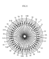
- Fig. 6 is a plan view showing a substrate of the microdevice.
- Fig. 7 is a bottom view showing a cover of the microdevice.
- Fig. 8 is a sectional view showing the operation for opening first gas discharge ports.
- Fig. 9 is a sectional view showing the operation for opening a second gas discharge port.
- Figs. 10 is a schematic view showing the movement of a sample liquid through flow paths.
- Fig. 11 is an exploded perspective view showing another example of microdevice according to the present invention.
- Fig. 12 is a sectional view of the microdevice shown in Fig. 11.
- Fig. 13 is a plan view showing a principal portion of a prior art analytical tool.
- Fig. 14 is a sectional view taken along lines XVI-XVI in Fig. 13.
- Fig. 15 is an exploded perspective view showing another example of prior art analytical tool.
- Fig. 16 is a sectional view showing a principal portion of the analytical tool shown in Fig. 15.
-
- Figs. 1 and 2 show an analytical apparatus X to which a microdevice Y as an analytical tool is mounted for analyzing a sample liquid. The apparatus includes a
mount portion 1 to which the microdevice Y is to be mounted, alight source 2, alight receiving portion 3 and anopening mechanism 4. - As better shown in Figs. 3 through 5, the microdevice Y, which serves to provide a reaction field, includes a
substrate 5, acover 6, anadhesive layer 7 and aseparation film 8. - The
substrate 5 comprises a transparent circular disk having a circumferential edge which is stepped downwardly. As shown in Figs. 5A and 6, thesubstrate 5 includes aliquid receiving portion 50 formed at the center thereof, a plurality offlowpaths 51 communicating with theliquid receiving portion 50 and extending radially from theliquid receiving portion 50 toward the circumferential edge of thesubstrate 4 , a plurality ofrecesses 52 and a plurality of branchingflow paths 53. - The
liquid receiving portion 50 serves to retain a sample liquid supplied to the microdevice Y for introduction to each of theflow paths 51. Theliquid receiving portion 50 comprises a circular recess formed on anupper surface 5A of thesubstrate 5. - Each of the
flow paths 51 serves to move the sample liquid and is formed on theupper surface 5A of thesubstrate 5 so as to communicate with theliquid receiving portion 50. As shown in Fig. 5A, eachflow path 51 includes achannel 51A and areaction portion 51B. Theflow path 51 has a generally uniform rectangular cross section except for thereaction portion 51B. For example, the width and depth of the rectangular cross section of theflowpath 51 are set to 10~500 µm and 5~500 µm, respectively, and set so that the depth/width ratio is no smaller than 0.5. - As shown in Figs. 4 and 6, from the
channel 51A extends the branchingflow path 53 communicating with theflow path 51. The branchingflow path 53 is provided as close to thereaction portion 51B as possible so that the distance between the branchingflow path 53 and thereaction portion 51B becomes as small as possible. The branchingflow path 53 has a generally uniform rectangular cross section of a dimension similar to the rectangular cross section of the flow path. - Each of the
reaction portions 51B has a sectional area which is larger than that of the principal cross section of theflow path 51. Thereaction portions 51B are arranged on a common circle. As shown in Fig. 5A, each of thereaction portions 51B is provided with areagent portion 54. However, thereagent portion 54 need not necessarily be provided at everyflow path 51. For example, a reagent portion may not be provided with respect to a flow path that is used for correcting the influence of the color of a sample liquid. - The
reagent portion 54 comprises a solid which dissolves when a sample liquid is supplied thereto and exhibits a color upon reacting with a particular component contained in the sample liquid. In this embodiment, a plurality of kinds ofreagent portions 54 which differ from each other in components or composition are prepared so that a plurality of items can be measured in the microdevice Y. - Each of the
recesses 52 serves to emit a light toward thelower surface 5B side of thesubstrate 5 when thereaction portion 51B is irradiated with light from theupper surface 5A side of thesubstrate 5 and the light is transmitted to the recess, as will be described later (See Figs. 1 and 2). Therecess 52 is provided at thelower surface 5B of thesubstrate 5 at a location corresponding to thereaction portion 51B. Therefore, as shown in Fig. 6, therecesses 52 are arranged on the same circle and adjacent to the circumferential edge of thesubstrate 5. - For example, the
substrate 5 is made by molding a transparent resin material such as acrylic resin such as polymethyl methacrylate (PMMA), or polystyrene (PS), polycarbonate (PC) or polyethylene terephthalate (PET). Theliquid receiving portion 50, the flow paths 51, therecesses 52 and the branchingflow paths 53 can be made at the same time in the resin-molding process by appropriately designing the configuration of the mold. - Preferably, the inner surfaces of the
liquid receiving portion 50, theflow paths 51, therecesses 52 and the branchingflow paths 53 are hydrophilically treated. Although various known techniques for hydrophilization can be employed, it is preferable that hydrophilization is performed by bringing a mixed gas containing fluorine gas and oxygen gas into contact with each inner surface and then bringing water or water vapor into contact with the inner surface. Unlike a prior art hydrophilization technique such as ultraviolet irradiation, this method is capable of hydrophilically treating a standing surface (side surface of a flow path, for example) as well, because this method utilizes gas and water forhydrophilization. The hydrophilization with respect to each inner surface is so performed that the contact angle of pure water at the inner surface becomes 0∼80 degrees, and preferably 0∼60 degrees. - The
cover 6 is in the form of a circular disk having a downwardly projecting circumferential edge. Theprojection 60 of thecover 6 serves to engage the stepped, smaller-thickness portion of thesubstrate 5. As shown in Figs. 5 and 7, thecover 6 includes asample introduction port 61, a plurality of firstgas discharge ports 62, a plurality ofrecesses 63, acommon flow path 64 and a secondgas discharge port 65. - The
sample introduction port 61, which is used for introducing a sample liquid, comprises a through-hole. As better shown in Fig. 5, thesample introduction port 61 is provided at the center of thecover 6 and directly above theliquid receiving portion 50 of thesubstrate 5. - Each of the first
gas discharge ports 62, which are used for discharging gas from theflow paths 51, comprises a through-hole. As better shown in Fig. 5B, the firstgas discharge ports 62 are provided directly above the branchingflow paths 53 of thesubstrate 5, respectively. As a result, as shown in Figs. 4 and 7, the firstgas discharge ports 62 are arranged on a common circle. As better shown in Fig. 5B, the upper opening of each of the firstgas discharge ports 62 is closed by a sealingmember 62a. The sealingmember 62a may be made of metal such as aluminum or resin. The sealingmember 62a is fixed to thesubstrate 5 by the use of an adhesive or by fusing, for example. - The
recesses 63 are utilized for irradiating thereaction portions 51B with light from theupper surface 6A side of thecover 6, as will be described later (See Figs. 1 and 2). As shown in Fig. 5A, each of therecesses 63 is provided at theupper surface 6A of thecover 6 and directly above thereaction portion 51B. As a result, as shown in Figs. 4 and 7, therecesses 63 are arranged on a common circle and adjacent to the circumferential edge of thecover 6. - The
common flow path 64 serves to guide gas to the secondgas discharge port 65 in discharging gas in thefluid paths 51 to the outside. As shown in Figs. 5 and 7, thecommon flow path 64 comprises an annular recess provided at a peripheral portion of thelower surface 6B of thecover 6. As shown in Figs. 5A and 6, thecommon flow path 64 communicates with theflow paths 51 of thesubstrate 5. - As shown in Figs. 5A and 7, the second
gas discharge port 65 comprises a through-hole communicating with thecommon flow path 64. The upper opening of the secondgas discharge port 65 is closed by a sealingmember 65a. As the sealingmember 65a, use may be made of one that is similar to the sealingmember 62a. - Similarly to the
substrate 5, thecover 6 may be made by resin-molding using a transparent resin material. Thesample introduction port 61, the firstgas discharge ports 62, therecesses 63, thecommon flow path 64 and the secondgas discharge port 65 can be made at the same time in the resin-molding process. It is preferable that thecover 6 as well is hydrophilically treated at least at the portion facing theflow paths 51 of thesubstrate 5. The hydrophilization can be performed by the same technique as that for thesubstrate 5. - As better shown in Fig. 5, the
adhesive layer 7 serves to bond thecover 6 to thesubstrate 5. As shown in Figs. 4 and 5, theadhesive layer 7 is provided by interposing an adhesive sheet, which is formed with a through-hole 70 at the center thereof, between thesubstrate 5 and thecover 6. The through-hole 70 of theadhesive layer 7 has a diameter which is larger than those of theliquid receiving portion 50 of thesubstrate 5 and thesample introduction port 61 of thecover 6. The adhesive sheet may be made by forming adhesive layers at opposite surfaces of a base material. - The
separation film 8 serves to separate solid components contained in a sample liquid such as blood cells in blood. As shown in Fig. 5, theseparation film 5 has a diameter corresponding to the diameter of the through-hole 70 of theadhesive layer 7 and is fitted into the through-hole 70 of theadhesive layer 7 to intervene between the liquid receivingportion 50 of thesubstrate 5 and thesample introduction port 61 of thecover 6. Since theliquid receiving portion 50 comprises a recess, theseparation film 8 is spaced from the bottom surface of theliquid receiving portion 50. Since the diameter of theseparation film 8 corresponds to the diameter of the through-hole 70 which is larger than that of theliquid receiving portion 50, each of theflow paths 51 is covered by theseparation film 8 at a portion which is close to theliquid receiving portion 50. By such an arrangement of theseparation film 8, the sample liquid introduced through thesample introduction port 61 passes through theseparation film 8 in the thickness direction and then reaches theliquid receiving portion 50. - As the
separation film 8, a porous material may be used, for example. Examples of porous material used as theseparation film 8 includes paper, foam (expanded material), an woven material, a non-woven material, a knitted material, a membrane filter, a glass filter, or a gel material. When the sample liquid is blood and blood cells in the blood are to be separated in theseparation film 8, it is preferable to use, as theseparation film 8, a material whose minimum pore diameter (pore size) is 0.1∼3.0 µm. - The
mount portion 1 shown in Figs. 1 and 2 includes arecess 10 for holding the microdevice Y. In themount portion 1 is defined alight transmitting region 11. Thelight transmitting region 11 is provided at a location which corresponds to thereaction portion 51B when the microdevice Y is mounted to therecess 10. Thelight transmitting portion 11 is provided by forming the relevant region of themount portion 1 by using a transparent material such as transparent resin. Alternatively, themount portion 1 may be entirely made of a transparent material. Themount portion 1 is supported by arotation shaft 12 so that themount portion 1 rotates in accordance with the rotation of therotation shaft 12. Therotation shaft 12 is connected to a non-illustrated driving mechanism and is controlled to rotate by a predetermined angle corresponding to the arrangement pitch of thereaction portions 51B of the microdevice Y. - The
light source 2 serves to irradiate thereaction portions 51B of the microdevice Y with light and is fixed at a position for facing therecesses 63 of thecover 6. Thelight source 2 may comprise a mercury lamp or a white LED, for example. Though not illustrated, when such a light source is used, the light from thelight source 2 is caused to pass through a filter before reaching thereaction portions 51B. By using such a filter, it is possible to select a light of an appropriate wavelength in accordance with the light absorption characteristics of the substance as an object to be analyzed contained in the reaction liquid. - The
light receiving portion 3 serves to receive light passed through thereaction portion 51B and is fixed at a position for facing therecesses 52 of thesubstrate 5. The amount of light received by thelight receiving portion 3 is used as the base for the analysis of the sample liquid (for the concentration computation, for example). Thelight receiving portion 3 may comprise a photodiode, for example. - The
opening mechanism 4 includes a first hole-makingmember 41 for making a hole in theseal portion 62a, and a second hole-makingmember 42 for making a hole in theseal portion 65a. The hole-makingmembers - The first hole-making
member 41 includes asubstrate 41a in the form of a circular disk, and a plurality ofneedles 41b projecting downward from the lower surface of the substrate. As shown in Fig. 8, each of theneedles 41b has a diameter which is smaller than that of the firstgas discharge ports 62 of thecover 6. Theneedles 41b are arranged on a common circle and at a pitch corresponding to the pitch of the firstgas discharge ports 62. Therefore, when the first hole-makingmember 41 is moved downward with theneedles 41b positioned to face the firstgas discharge ports 62, respectively, holes can be made simultaneously with respect to the plurality ofseal portions 62a. By this operation, each of the firstgas discharge ports 62 opens, whereby the interior of eachflow path 51 is brought into communication with the outside through the branchingflow path 53 and the firstgas discharge port 62. - As shown in Figs. 1 and 9, the second hole-making
member 42 includes aneedle 42a. Theneedle 42a has a diameter which is smaller than that of the secondgas discharge port 65 of thecover 6. Therefore, when the second hole-makingmember 42 is moved downward with theneedle 42a of the second hole-makingmember 42 positioned to face the secondgas discharge port 65 of thecover 6, a hole is made in theseal portion 65a. By this operation, the secondgas discharge port 65 opens, whereby the interior of eachflow path 51 is brought into communication with the outside through thecommon flow path 64 and the secondgas discharge port 65. - The method for opening the first and the second
gas discharge ports gas discharge ports members sealing members gas discharge ports members - For analyzing a sample liquid, the sample liquid S is supplied to the microdevice Y through the
sample introduction port 61. The supply of the sample liquid S may be performed after the microdevice Y is mounted to the analytical apparatus X. However, it is preferable that the microdevice Y is mounted to the analytical apparatus X after the sample liquid S is supplied to the microdevice Y. - As will be understood from Fig. 5, when the sample liquid S is supplied to the microdevice Y, the sample liquid S passes through the
separation film 8 in the thickness direction of the film to reach theliquid receiving portion 50. At this time, solid components are removed from the sample liquid S. For example, when blood is used as the sample liquid, blood cells are removed from the blood. Since the first and the secondgas discharge ports liquid receiving portion 50 and does not flow into theflow paths 51, as schematically shown in Fig. 10A. - In this embodiment, solid components are removed by moving the sample liquid in the thickness direction of the
separation film 8. Therefore, as compared with the structure in which solid components are removed by moving the sample liquid in the plane direction of theseparation film 8, the retention time of the sample liquid in theseparation film 8 becomes shorter. Therefore, the time necessary for removing solid components becomes shorter. - To introduce the sample liquid S to the
flow paths 51, holes are made simultaneously with respect to the plurality ofseal portions 62a. As shown in Fig. 8, the making of holes in theseal portions 62a is performed by moving the first hole-makingmember 41 downward to insert theneedles 41b into theseal portions 62a and then moving the first hole-makingmember 41 upward to remove theneedles 41b from theseal portions 62a. By this operation, holes are made simultaneously with respect to the plurality ofseal portions 62a. The upward and downward movement of the first hole-makingmember 41 may be performed automatically in the analytical apparatus X by the user's operation of an operation switch, for example. - When the holes are made at the
seal portions 62a, the interior of theflow paths 51 are brought into communication with the outside through the firstgas discharge ports 62 and the branchingflow paths 53. Therefore, the sample liquid S retained in theliquid receiving portion 50 moves through theflow paths 51 by capillary action. As indicated by arrows in Fig. 10A, when the sample liquid S reaches eachchannel 51A, the sample liquid S cannot move beyond thechannel 51A to reach thereaction portion 51B and is guided to the branchingflow path 53. As a result, as schematically shown in Fig. 10B, the sample liquid S is retained in close proximity to thereaction portion 51B. Thus, the preparation for the reaction of the sample liquid S with the reagent at thereaction portion 51B is completed. - To guide the sample liquid s to the
reaction portion 51B, a hole is made at theseal portion 65a. As shown in Fig. 9, the making of a hole at theseal portion 65a is performed by moving the second hole-makingmember 42 downward to insert theneedle 42a into theseal portion 65a and then moving the second hole-makingmember 42 upward to remove theneedle 42a from theseal portion 65a. The upward and downward movement of the second hole-makingmember 42 may be performed automatically in the analytical apparatus X by the user's operation of an operation switch, for example. - When the hole is made at the
seal portion 65a, the interior of eachflow path 51 is brought into communication with the outside through the secondgas discharge port 65 and thecommon flowpath 64. Therefore, the sample liquid S, which has stopped upstream from thereaction portion 51B, moves again through theflow path 51 by capillary action. Thus, as shown in Fig. 10C, the sample liquid S moves beyond thechannel 51A in eachflow path 51, whereby the sample liquid S is supplied collectively to the plurality ofreaction portions 51. - At each of the
reaction portions 51B, thereagent portion 54 is dissolved by the sample liquid to establish a liquid phase reaction system. As the sample liquid S reacts with the reagent, the liquid phase reaction system exhibits a color depending on the amount of the substance to be detected in the sample or a reaction product is produced in accordance with the amount of the substance to be detected. As a result, the liquid phase reaction system of thereaction portion 51B exhibits light transmission characteristics (light absorption characteristics) depending on the amount of the substance to be detected. When a predetermined time period has elapsed from the sample supply to thereaction portion 51B, thereaction portion 51B is irradiated with light from thelight source 2 shown in Figs. 1 and 2, and the amount of transmitted light is measured at thelight receiving portion 3. The light irradiation by thelight source 2 and the light receiving at thelight receiving portion 3 are performed with respect to each of thereaction portions 51B of theflow paths 51 by turning themount portion 1 by a predetermined angle. In the analytical apparatus X, the analysis of the sample, e.g. the computation of the concentration of a substance to be detected, is performed based on the amount of light received at thelight receiving portion 3. - In the above-described analysis method, after the sample liquid S is guided to a portion (each
channel 51A) close to thereaction portion 51B, the sample liquid S is supplied from thechannel 51A to thereaction portion 51B by opening theseal portion 65a. Thus, the sample liquid S can be supplied to thereaction portions 51B of the plurality offlow paths 51 just by opening a single gas discharge port. Therefore, the time taken from when the operation to supply the sample liquid S is performed (theseal portion 65a is opened) until when the sample liquid reaches thereaction portions 51B can be shortened. Accordingly, variation of the time taken from the sample supply starting operation to the completion of the sample supply among theflow paths 51 and among each measurement (among analytical tools) can be reduced. Thus, the timing at which the reaction starts at thereaction portions 51 can be properly controlled by the operation of opening theseal portion 65a. Particularly, in this embodiment, the sample liquid can be supplied simultaneously to the plurality ofreaction portions 51B just by opening a single gas discharge port. Therefore, it is possible to make the reaction time uniform among thereaction portions 51B and among a plurality of microdevices Y, whereby the measurement error can be reduced. - The present invention is not limited to the foregoing embodiments and may be modified in various ways. For example, the present invention is applicable to such a microdevice as shown in Figs. 11 and 12, which includes a plurality of sample introduction ports. The microdevice Y' shown in the figures includes a substrate 5', and a cover 6' bonded to the substrate via an adhesive sheet 7'. The substrate 5' includes a
sample flow path 51a' and areagent flow path 51b' respectively provided with liquid receivingportions reaction portion 51B' for causing reaction between the sample liquid and the reagent liquid. The cover 6'includes asample introduction port 61A and areagent introduction port 61B. The adhesive sheet 7' includes an opening 70' formed to expose the twoliquid receiving portions - In the analytical tool Y', the sample liquid and the reagent liquid respectively supplied through the
sample introduction port 61A and thereagent introduction port 61B move in the thickness direction of the separation film 8' to reach theliquid receiving portions 50A and 60B. Thereafter, the sample liquid and the reagent liquid move to thereaction portion 51B' by capillary action and undergo reaction at thereaction portion 51B'. The reaction product is analyzed by an optical method. - In the analytical tool Y' shown in Figs. 11 and 12, the separation film 8' is arranged to collectively cover the two
liquid receiving portions liquid receiving portions - Although the analysis based on the light which is transmitted when the reaction portion is irradiated with light is described in the foregoing embodiments, the present invention is also applicable to the sample analysis based on the light reflected from the reaction portion. The irradiation of the reaction portion and the measurement of the transmitted light need not necessarily be performed individually with respect to each reaction portion but may be performed collectively with respect to the plurality of reaction portions.
- The present invention is applicable to an analytical tool which is designed to move a mobile component by capillary action. Therefore, the invention is applicable to a tool for performing analysis by an electrochemical method as well as that for performing analysis by an optical method. Moreover, the invention is applicable not only to an analysis method in which a sample is moved but also to an analysis method in which a reagent is moved instead of a sample and a method in which a sample and a reagent are moved together with a carrier liquid. The application of the present invention is not limited to microdevices, and the invention is also applicable to other types of analytical tools.
Claims (16)
- An analytical tool comprising a liquid introduction port, one or a plurality of flow paths for moving a sample liquid introduced through the liquid introduction port, and a separation film for filtering the sample liquid supplied to the liquid introduction port and then introducing the sample liquid to said one or plurality of flow paths;
wherein the sample liquid is caused to move through the separation film in a thickness direction of the separation film for filtration. - The analytical tool according to claim 1, wherein the flow path is structured to move the sample liquid by capillary action.
- The analytical tool according to claim 1, wherein the sample liquid comprises blood, and
wherein the separation film separates blood cells from the blood. - The analytical tool according to claim 3, wherein the separation film comprises a porous film having a minimum pore size of 0.1-3.0 µm.
- The analytical tool according to claim 1, wherein the separation film is positioned higher than the flow path.
- The analytical tool according to claim 5, further comprising a liquid receivingportion for retaining the sample liquidpassed through the separation film, the liquid receiving portion communicating with the liquid introduction port and the flow path, and
wherein the separation film is spaced from a bottom surface of the liquid receiving portion. - The analytical tool according to claim 6, further comprising:a substrate inwhich the liquid receiving portion is formed;a cover in which the liquid introduction port is formed; andan adhesive layer interposed between the substrate and the cover, the adhesive layer including a through-hole for fitting the separation film.
- The analytical tool according to claim 6, wherein the plural ity of flowpaths extend radially from the liquid receiving portion.
- The analytical tool according to claim 1, wherein at least two of the plurality of flow paths are respectively provided with reagent portions for reaction with the sample liquid, each of the reagent portions of said at least two flowpaths containing a different reagent; and
wherein the tool is adapted to measure a plurality of items from a single kind of sample liquid. - The analytical tool according to claim 9, wherein the reagent portions of said at least two flow paths are arranged on a common circle.
- The analytical tool according to claim 9, wherein each of said at least two flow paths is structured to temporarily retain the sample liquid upstream from the reagent portion before the sample liquid is introduced to the reagent portion.
- The analytical tool according to claim 11, further comprising a branching flow path branched from a channel set of the flow path;
wherein the sample liquid is temporarily retained at the channel of the flow path by bringing the branching flow path into communication with outside through a portion other than the liquid introduction port, and the sample liquid is caused to move through the flow path beyond the channel by bringing the flow path into communication with outside through a portion other than the liquid introduction port. - The analytical tool according to claim 12, wherein the flow path is connected to a gas discharge port for discharging gas from the flow path, and the sample liquid is caused to move beyond the channel by opening the gas discharge port.
- The analytical tool according to claim 1, wherein the flow path has a principal, rectangular cross section which has a width of 10 to 500 µm and a depth of 5 to 500 µm and which satisfies depth/width 0.5.
- The analytical tool according to claim 1, wherein the flow path includes a hydrophilically-treated inner surface.
- The analytical tool according to claim 15, wherein the inner surface of the flow path is so treated that a contact angle of pure water at the inner surface becomes 0∼80 degrees.
Applications Claiming Priority (3)
| Application Number | Priority Date | Filing Date | Title |
|---|---|---|---|
| JP2002281101A JP4210783B2 (en) | 2002-09-26 | 2002-09-26 | Analysis tool |
| JP2002281101 | 2002-09-26 | ||
| PCT/JP2003/012295 WO2004029619A1 (en) | 2002-09-26 | 2003-09-25 | Analyzing tool |
Publications (3)
| Publication Number | Publication Date |
|---|---|
| EP1548433A1 true EP1548433A1 (en) | 2005-06-29 |
| EP1548433A4 EP1548433A4 (en) | 2010-10-20 |
| EP1548433B1 EP1548433B1 (en) | 2012-11-07 |
Family
ID=32040500
Family Applications (1)
| Application Number | Title | Priority Date | Filing Date |
|---|---|---|---|
| EP03798513A Expired - Lifetime EP1548433B1 (en) | 2002-09-26 | 2003-09-25 | Analyzing tool |
Country Status (6)
| Country | Link |
|---|---|
| US (1) | US7850909B2 (en) |
| EP (1) | EP1548433B1 (en) |
| JP (1) | JP4210783B2 (en) |
| CN (1) | CN100554961C (en) |
| AU (1) | AU2003266637A1 (en) |
| WO (1) | WO2004029619A1 (en) |
Cited By (1)
| Publication number | Priority date | Publication date | Assignee | Title |
|---|---|---|---|---|
| WO2011131471A1 (en) | 2010-04-23 | 2011-10-27 | Boehringer Ingelheim Microparts Gmbh | Device for plasma separation by means of a central channel structure |
Families Citing this family (6)
| Publication number | Priority date | Publication date | Assignee | Title |
|---|---|---|---|---|
| JP4262466B2 (en) | 2002-10-28 | 2009-05-13 | アークレイ株式会社 | Analysis tool and analyzer |
| JP4504289B2 (en) * | 2004-09-27 | 2010-07-14 | シチズンホールディングス株式会社 | Biosensor |
| EP1912074B1 (en) | 2005-07-29 | 2014-04-23 | ARKRAY, Inc. | Analyzer |
| JP6251192B2 (en) * | 2012-01-24 | 2017-12-20 | コーニンクレッカ フィリップス エヌ ヴェKoninklijke Philips N.V. | Analysis cartridge using filter unit |
| JP7227039B2 (en) * | 2019-03-13 | 2023-02-21 | 日東電工株式会社 | Flow path, measuring tape, and measuring device |
| JP7227040B2 (en) * | 2019-03-13 | 2023-02-21 | 日東電工株式会社 | Measuring device, flow path, measuring tape, and measuring method |
Citations (4)
| Publication number | Priority date | Publication date | Assignee | Title |
|---|---|---|---|---|
| EP0269240A1 (en) * | 1986-10-29 | 1988-06-01 | Biotrack, Inc. | Blood separation device under low pressure conditions |
| US4933092A (en) * | 1989-04-07 | 1990-06-12 | Abbott Laboratories | Methods and devices for the separation of plasma or serum from whole blood |
| DE10013242A1 (en) * | 1999-03-17 | 2000-11-16 | Hitachi Ltd | Apparatus for analyzing components of bodily fluids, e.g. blood, has a discharge unit which sequentially discharges a reagent which is different for each reaction area of the hold-back carrier |
| US20020047003A1 (en) * | 2000-06-28 | 2002-04-25 | William Bedingham | Enhanced sample processing devices, systems and methods |
Family Cites Families (25)
| Publication number | Priority date | Publication date | Assignee | Title |
|---|---|---|---|---|
| EP0305210B1 (en) | 1987-08-27 | 1993-12-08 | Biotrack, Inc. | Apparatus and method for dilution and mixing of liquid samples |
| US4868129A (en) * | 1987-08-27 | 1989-09-19 | Biotrack Inc. | Apparatus and method for dilution and mixing of liquid samples |
| JPH0359457A (en) | 1989-07-27 | 1991-03-14 | Terumo Corp | Testing tool |
| US5460974A (en) | 1992-10-13 | 1995-10-24 | Miles Inc. | Method of assaying whole blood for HDL cholesterol |
| JPH10501340A (en) | 1994-06-06 | 1998-02-03 | アバクシス,インコーポレイテッド | Improved siphon to improve measurement accuracy |
| CA2156226C (en) | 1994-08-25 | 1999-02-23 | Takayuki Taguchi | Biological fluid analyzing device and method |
| JPH08105901A (en) | 1994-10-06 | 1996-04-23 | Nittec Co Ltd | Automatic analyzing device |
| CA2211190A1 (en) | 1995-01-25 | 1996-08-01 | Therakos, Inc. | Disposable hemolysis detector |
| JP3881731B2 (en) | 1996-04-19 | 2007-02-14 | 征夫 軽部 | Enzyme reaction sensor and manufacturing method thereof |
| US5821073A (en) | 1996-05-09 | 1998-10-13 | Syntron Bioresearch, Inc. | Method and apparatus for single step assays of whole blood |
| US6391265B1 (en) | 1996-08-26 | 2002-05-21 | Biosite Diagnostics, Inc. | Devices incorporating filters for filtering fluid samples |
| JP2953418B2 (en) | 1997-01-09 | 1999-09-27 | 日本電気株式会社 | Biochemical analyzer |
| JPH10206417A (en) | 1997-01-24 | 1998-08-07 | Advance Co Ltd | Blood chemical analysis material and blood chemical analysis method |
| US6632399B1 (en) * | 1998-05-22 | 2003-10-14 | Tecan Trading Ag | Devices and methods for using centripetal acceleration to drive fluid movement in a microfluidics system for performing biological fluid assays |
| JP2002508698A (en) * | 1997-08-25 | 2002-03-19 | バイオサイト・ダイアグノスティックス・インコーポレーテッド | Device incorporating a filter for filtering a fluid sample |
| CN1191786C (en) * | 1999-01-04 | 2005-03-09 | 泰尔茂株式会社 | Assembly having lancet and means for collecting and detecting body fluid |
| JP3648081B2 (en) | 1999-01-04 | 2005-05-18 | テルモ株式会社 | Body fluid component measuring device |
| JP2001050952A (en) | 1999-08-12 | 2001-02-23 | Kunimune Kogyosho:Kk | Plasma separation collection method and tool thereof |
| JP2002071684A (en) | 2000-08-25 | 2002-03-12 | Wako Pure Chem Ind Ltd | Multi-item vital component measuring test implement and its manufacturing method |
| EP1118859A2 (en) * | 2000-01-21 | 2001-07-25 | Wako Pure Chemical Industries Ltd | A test device for a multi-items test and the method for producing the same as well as measuring instrument for the test device |
| US6615856B2 (en) * | 2000-08-04 | 2003-09-09 | Biomicro Systems, Inc. | Remote valving for microfluidic flow control |
| JP2002202310A (en) | 2000-10-27 | 2002-07-19 | Morinaga Milk Ind Co Ltd | Substance detecting reagent and substance detecting method |
| JP3510597B2 (en) | 2001-02-09 | 2004-03-29 | 俊逸 通木 | Blood separation device and blood test method |
| JP4797196B2 (en) * | 2001-02-14 | 2011-10-19 | 株式会社 フューエンス | Microchip |
| JP4262466B2 (en) * | 2002-10-28 | 2009-05-13 | アークレイ株式会社 | Analysis tool and analyzer |
-
2002
- 2002-09-26 JP JP2002281101A patent/JP4210783B2/en not_active Expired - Fee Related
-
2003
- 2003-09-25 WO PCT/JP2003/012295 patent/WO2004029619A1/en active Application Filing
- 2003-09-25 AU AU2003266637A patent/AU2003266637A1/en not_active Abandoned
- 2003-09-25 EP EP03798513A patent/EP1548433B1/en not_active Expired - Lifetime
- 2003-09-25 US US10/529,120 patent/US7850909B2/en active Active
- 2003-09-25 CN CNB038230860A patent/CN100554961C/en not_active Expired - Fee Related
Patent Citations (4)
| Publication number | Priority date | Publication date | Assignee | Title |
|---|---|---|---|---|
| EP0269240A1 (en) * | 1986-10-29 | 1988-06-01 | Biotrack, Inc. | Blood separation device under low pressure conditions |
| US4933092A (en) * | 1989-04-07 | 1990-06-12 | Abbott Laboratories | Methods and devices for the separation of plasma or serum from whole blood |
| DE10013242A1 (en) * | 1999-03-17 | 2000-11-16 | Hitachi Ltd | Apparatus for analyzing components of bodily fluids, e.g. blood, has a discharge unit which sequentially discharges a reagent which is different for each reaction area of the hold-back carrier |
| US20020047003A1 (en) * | 2000-06-28 | 2002-04-25 | William Bedingham | Enhanced sample processing devices, systems and methods |
Non-Patent Citations (1)
| Title |
|---|
| See also references of WO2004029619A1 * |
Cited By (1)
| Publication number | Priority date | Publication date | Assignee | Title |
|---|---|---|---|---|
| WO2011131471A1 (en) | 2010-04-23 | 2011-10-27 | Boehringer Ingelheim Microparts Gmbh | Device for plasma separation by means of a central channel structure |
Also Published As
| Publication number | Publication date |
|---|---|
| AU2003266637A1 (en) | 2004-04-19 |
| EP1548433B1 (en) | 2012-11-07 |
| WO2004029619A1 (en) | 2004-04-08 |
| CN1685231A (en) | 2005-10-19 |
| EP1548433A4 (en) | 2010-10-20 |
| CN100554961C (en) | 2009-10-28 |
| JP2004117178A (en) | 2004-04-15 |
| US7850909B2 (en) | 2010-12-14 |
| US20060045799A1 (en) | 2006-03-02 |
| JP4210783B2 (en) | 2009-01-21 |
Similar Documents
| Publication | Publication Date | Title |
|---|---|---|
| JP4262466B2 (en) | Analysis tool and analyzer | |
| JP4262674B2 (en) | Analytical tool, sample analysis method and analytical device using analytical tool | |
| EP2200744B1 (en) | An analysis system | |
| US6104484A (en) | Measuring chip for optical analyzer | |
| EP0593714B1 (en) | Analytical cartridge and system for detecting analytes | |
| EP1775592A1 (en) | Analyzer, method for specifying reaction vessel in analyzer, and analytical apparatus | |
| EP1612430A2 (en) | Methods for modulation of flow in a microfluidic pathway | |
| EP1612429A2 (en) | Microfluidic flow modulation device | |
| US9976963B2 (en) | Microcuvette cartridge | |
| EP1548433A1 (en) | Analyzing tool | |
| US6607701B1 (en) | Production of microcuvettes | |
| CN111629830B (en) | Sample rack | |
| KR20150101308A (en) | Microfluidic Device and Microfluidic System Including thereof | |
| JP2018511061A (en) | Device for collecting liquid samples using capillary action |
Legal Events
| Date | Code | Title | Description |
|---|---|---|---|
| PUAI | Public reference made under article 153(3) epc to a published international application that has entered the european phase |
Free format text: ORIGINAL CODE: 0009012 |
|
| 17P | Request for examination filed |
Effective date: 20050408 |
|
| AK | Designated contracting states |
Kind code of ref document: A1 Designated state(s): AT BE BG CH CY CZ DE DK EE ES FI FR GB GR HU IE IT LI LU MC NL PT RO SE SI SK TR |
|
| AX | Request for extension of the european patent |
Extension state: AL LT LV MK |
|
| DAX | Request for extension of the european patent (deleted) | ||
| A4 | Supplementary search report drawn up and despatched |
Effective date: 20100921 |
|
| 17Q | First examination report despatched |
Effective date: 20110203 |
|
| REG | Reference to a national code |
Ref country code: DE Ref legal event code: R079 Ref document number: 60342554 Country of ref document: DE Free format text: PREVIOUS MAIN CLASS: G01N0033480000 Ipc: G01N0021070000 |
|
| GRAP | Despatch of communication of intention to grant a patent |
Free format text: ORIGINAL CODE: EPIDOSNIGR1 |
|
| RIC1 | Information provided on ipc code assigned before grant |
Ipc: G01N 21/07 20060101AFI20120529BHEP Ipc: B01L 3/00 20060101ALI20120529BHEP |
|
| GRAS | Grant fee paid |
Free format text: ORIGINAL CODE: EPIDOSNIGR3 |
|
| GRAA | (expected) grant |
Free format text: ORIGINAL CODE: 0009210 |
|
| AK | Designated contracting states |
Kind code of ref document: B1 Designated state(s): AT BE BG CH CY CZ DE DK EE ES FI FR GB GR HU IE IT LI LU MC NL PT RO SE SI SK TR |
|
| REG | Reference to a national code |
Ref country code: GB Ref legal event code: FG4D |
|
| REG | Reference to a national code |
Ref country code: CH Ref legal event code: EP Ref country code: AT Ref legal event code: REF Ref document number: 583200 Country of ref document: AT Kind code of ref document: T Effective date: 20121115 |
|
| REG | Reference to a national code |
Ref country code: IE Ref legal event code: FG4D |
|
| REG | Reference to a national code |
Ref country code: DE Ref legal event code: R096 Ref document number: 60342554 Country of ref document: DE Effective date: 20130103 |
|
| REG | Reference to a national code |
Ref country code: AT Ref legal event code: MK05 Ref document number: 583200 Country of ref document: AT Kind code of ref document: T Effective date: 20121107 |
|
| REG | Reference to a national code |
Ref country code: NL Ref legal event code: VDEP Effective date: 20121107 |
|
| PG25 | Lapsed in a contracting state [announced via postgrant information from national office to epo] |
Ref country code: SE Free format text: LAPSE BECAUSE OF FAILURE TO SUBMIT A TRANSLATION OF THE DESCRIPTION OR TO PAY THE FEE WITHIN THE PRESCRIBED TIME-LIMIT Effective date: 20121107 Ref country code: FI Free format text: LAPSE BECAUSE OF FAILURE TO SUBMIT A TRANSLATION OF THE DESCRIPTION OR TO PAY THE FEE WITHIN THE PRESCRIBED TIME-LIMIT Effective date: 20121107 Ref country code: NL Free format text: LAPSE BECAUSE OF FAILURE TO SUBMIT A TRANSLATION OF THE DESCRIPTION OR TO PAY THE FEE WITHIN THE PRESCRIBED TIME-LIMIT Effective date: 20121107 |
|
| PG25 | Lapsed in a contracting state [announced via postgrant information from national office to epo] |
Ref country code: GR Free format text: LAPSE BECAUSE OF FAILURE TO SUBMIT A TRANSLATION OF THE DESCRIPTION OR TO PAY THE FEE WITHIN THE PRESCRIBED TIME-LIMIT Effective date: 20130208 Ref country code: SI Free format text: LAPSE BECAUSE OF FAILURE TO SUBMIT A TRANSLATION OF THE DESCRIPTION OR TO PAY THE FEE WITHIN THE PRESCRIBED TIME-LIMIT Effective date: 20121107 Ref country code: BE Free format text: LAPSE BECAUSE OF FAILURE TO SUBMIT A TRANSLATION OF THE DESCRIPTION OR TO PAY THE FEE WITHIN THE PRESCRIBED TIME-LIMIT Effective date: 20121107 Ref country code: PT Free format text: LAPSE BECAUSE OF FAILURE TO SUBMIT A TRANSLATION OF THE DESCRIPTION OR TO PAY THE FEE WITHIN THE PRESCRIBED TIME-LIMIT Effective date: 20130307 Ref country code: CY Free format text: LAPSE BECAUSE OF FAILURE TO SUBMIT A TRANSLATION OF THE DESCRIPTION OR TO PAY THE FEE WITHIN THE PRESCRIBED TIME-LIMIT Effective date: 20121107 |
|
| PG25 | Lapsed in a contracting state [announced via postgrant information from national office to epo] |
Ref country code: AT Free format text: LAPSE BECAUSE OF FAILURE TO SUBMIT A TRANSLATION OF THE DESCRIPTION OR TO PAY THE FEE WITHIN THE PRESCRIBED TIME-LIMIT Effective date: 20121107 |
|
| PG25 | Lapsed in a contracting state [announced via postgrant information from national office to epo] |
Ref country code: EE Free format text: LAPSE BECAUSE OF FAILURE TO SUBMIT A TRANSLATION OF THE DESCRIPTION OR TO PAY THE FEE WITHIN THE PRESCRIBED TIME-LIMIT Effective date: 20121107 Ref country code: BG Free format text: LAPSE BECAUSE OF FAILURE TO SUBMIT A TRANSLATION OF THE DESCRIPTION OR TO PAY THE FEE WITHIN THE PRESCRIBED TIME-LIMIT Effective date: 20130207 Ref country code: DK Free format text: LAPSE BECAUSE OF FAILURE TO SUBMIT A TRANSLATION OF THE DESCRIPTION OR TO PAY THE FEE WITHIN THE PRESCRIBED TIME-LIMIT Effective date: 20121107 Ref country code: SK Free format text: LAPSE BECAUSE OF FAILURE TO SUBMIT A TRANSLATION OF THE DESCRIPTION OR TO PAY THE FEE WITHIN THE PRESCRIBED TIME-LIMIT Effective date: 20121107 Ref country code: CZ Free format text: LAPSE BECAUSE OF FAILURE TO SUBMIT A TRANSLATION OF THE DESCRIPTION OR TO PAY THE FEE WITHIN THE PRESCRIBED TIME-LIMIT Effective date: 20121107 |
|
| PG25 | Lapsed in a contracting state [announced via postgrant information from national office to epo] |
Ref country code: RO Free format text: LAPSE BECAUSE OF FAILURE TO SUBMIT A TRANSLATION OF THE DESCRIPTION OR TO PAY THE FEE WITHIN THE PRESCRIBED TIME-LIMIT Effective date: 20121107 |
|
| PLBE | No opposition filed within time limit |
Free format text: ORIGINAL CODE: 0009261 |
|
| STAA | Information on the status of an ep patent application or granted ep patent |
Free format text: STATUS: NO OPPOSITION FILED WITHIN TIME LIMIT |
|
| 26N | No opposition filed |
Effective date: 20130808 |
|
| PG25 | Lapsed in a contracting state [announced via postgrant information from national office to epo] |
Ref country code: ES Free format text: LAPSE BECAUSE OF FAILURE TO SUBMIT A TRANSLATION OF THE DESCRIPTION OR TO PAY THE FEE WITHIN THE PRESCRIBED TIME-LIMIT Effective date: 20130218 |
|
| REG | Reference to a national code |
Ref country code: DE Ref legal event code: R097 Ref document number: 60342554 Country of ref document: DE Effective date: 20130808 |
|
| PG25 | Lapsed in a contracting state [announced via postgrant information from national office to epo] |
Ref country code: MC Free format text: LAPSE BECAUSE OF FAILURE TO SUBMIT A TRANSLATION OF THE DESCRIPTION OR TO PAY THE FEE WITHIN THE PRESCRIBED TIME-LIMIT Effective date: 20121107 |
|
| REG | Reference to a national code |
Ref country code: CH Ref legal event code: PL |
|
| REG | Reference to a national code |
Ref country code: IE Ref legal event code: MM4A |
|
| PG25 | Lapsed in a contracting state [announced via postgrant information from national office to epo] |
Ref country code: LI Free format text: LAPSE BECAUSE OF NON-PAYMENT OF DUE FEES Effective date: 20130930 Ref country code: IE Free format text: LAPSE BECAUSE OF NON-PAYMENT OF DUE FEES Effective date: 20130925 Ref country code: CH Free format text: LAPSE BECAUSE OF NON-PAYMENT OF DUE FEES Effective date: 20130930 |
|
| PG25 | Lapsed in a contracting state [announced via postgrant information from national office to epo] |
Ref country code: TR Free format text: LAPSE BECAUSE OF FAILURE TO SUBMIT A TRANSLATION OF THE DESCRIPTION OR TO PAY THE FEE WITHIN THE PRESCRIBED TIME-LIMIT Effective date: 20121107 |
|
| PG25 | Lapsed in a contracting state [announced via postgrant information from national office to epo] |
Ref country code: LU Free format text: LAPSE BECAUSE OF NON-PAYMENT OF DUE FEES Effective date: 20130925 Ref country code: HU Free format text: LAPSE BECAUSE OF FAILURE TO SUBMIT A TRANSLATION OF THE DESCRIPTION OR TO PAY THE FEE WITHIN THE PRESCRIBED TIME-LIMIT; INVALID AB INITIO Effective date: 20030925 |
|
| REG | Reference to a national code |
Ref country code: FR Ref legal event code: PLFP Year of fee payment: 14 |
|
| REG | Reference to a national code |
Ref country code: FR Ref legal event code: PLFP Year of fee payment: 15 |
|
| REG | Reference to a national code |
Ref country code: FR Ref legal event code: PLFP Year of fee payment: 16 |
|
| REG | Reference to a national code |
Ref country code: DE Ref legal event code: R082 Ref document number: 60342554 Country of ref document: DE |
|
| PGFP | Annual fee paid to national office [announced via postgrant information from national office to epo] |
Ref country code: GB Payment date: 20220920 Year of fee payment: 20 Ref country code: DE Payment date: 20220920 Year of fee payment: 20 |
|
| PGFP | Annual fee paid to national office [announced via postgrant information from national office to epo] |
Ref country code: FR Payment date: 20220922 Year of fee payment: 20 |
|
| PGFP | Annual fee paid to national office [announced via postgrant information from national office to epo] |
Ref country code: IT Payment date: 20220926 Year of fee payment: 20 |
|
| REG | Reference to a national code |
Ref country code: DE Ref legal event code: R071 Ref document number: 60342554 Country of ref document: DE |
|
| REG | Reference to a national code |
Ref country code: GB Ref legal event code: PE20 Expiry date: 20230924 |
|
| PG25 | Lapsed in a contracting state [announced via postgrant information from national office to epo] |
Ref country code: GB Free format text: LAPSE BECAUSE OF EXPIRATION OF PROTECTION Effective date: 20230924 |