EP1550416A1 - Instrument augments for filling a bone joint gap - Google Patents
Instrument augments for filling a bone joint gap Download PDFInfo
- Publication number
- EP1550416A1 EP1550416A1 EP04258129A EP04258129A EP1550416A1 EP 1550416 A1 EP1550416 A1 EP 1550416A1 EP 04258129 A EP04258129 A EP 04258129A EP 04258129 A EP04258129 A EP 04258129A EP 1550416 A1 EP1550416 A1 EP 1550416A1
- Authority
- EP
- European Patent Office
- Prior art keywords
- instrument
- augment
- gap
- bore
- establishing
- Prior art date
- Legal status (The legal status is an assumption and is not a legal conclusion. Google has not performed a legal analysis and makes no representation as to the accuracy of the status listed.)
- Withdrawn
Links
Images


Classifications
-
- A—HUMAN NECESSITIES
- A61—MEDICAL OR VETERINARY SCIENCE; HYGIENE
- A61B—DIAGNOSIS; SURGERY; IDENTIFICATION
- A61B17/00—Surgical instruments, devices or methods, e.g. tourniquets
- A61B17/14—Surgical saws ; Accessories therefor
- A61B17/15—Guides therefor
- A61B17/154—Guides therefor for preparing bone for knee prosthesis
- A61B17/155—Cutting femur
-
- A—HUMAN NECESSITIES
- A61—MEDICAL OR VETERINARY SCIENCE; HYGIENE
- A61B—DIAGNOSIS; SURGERY; IDENTIFICATION
- A61B17/00—Surgical instruments, devices or methods, e.g. tourniquets
- A61B17/02—Surgical instruments, devices or methods, e.g. tourniquets for holding wounds open; Tractors
- A61B17/025—Joint distractors
- A61B2017/0268—Joint distractors for the knee
Definitions
- the present invention relates to devices for use in orthopaedic surgery, and especially for proper alignment of surgical instruments used in preparing a bone for an implant.
- the invention has particular application in preparing the distal end of the femur to receive a femoral prosthesis.
- a mobile bearing knee simulates the condylar and bearing surfaces of the knee to emulate the natural movement of the knee during flexion and extension.
- the tibial component is configured to permit rotation about the axis of the tibia to accurately replicate the effects of differential rollback in the transverse plane.
- Implantable mobile bearing knee prostheses such as the prosthesis 10 shown in FIG. 1, for diseased and/or damaged knees typically include three components, namely a tibial component 12, a femoral component 16 and a meniscal component (not shown).
- the tibial component 12 includes a platform 13 with a stem 14 configured for engagement in the prepared proximal end of the tibia.
- the platform 13 replaces the entire superior surface of the tibial plateau and substitutes for the tibial condylar surfaces.
- the femoral component can also include laterally-spaced condylar portions joined by an inter-condylar bridge and a patellar surface.
- the femoral component 16 defines interior mounting surfaces 17 that often require involved cuts into the distal end of the femur. Since the components of the mobile bearing knee prosthesis 10 are generally configured to restore or emulate as much of the natural motion of the knee joint as possible, the femoral component often has a complicated geometry, which requires significant modification to the femur to accept and support the implant. The selection of the particular prosthesis components is usually dictated by the condition of the patient's knee. For instance, the condition of the distal end of the femur and proximal end of the tibia, as well as the patency of the surrounding ligaments and soft tissue can affect the form of the joint prosthesis.
- implant positioning with respect to the natural bone is critical. For instance, a proper implant will maintain the proper tension in the retained ligaments supporting the joint.
- the menisci, bone ends and other stabilizing tissues are removed and replaced with implants.
- the thicknesses of the implants are ideally equal to the thickness of the removed material. Exceptions occur in reconstruction of severe deformity, where ligament length and tension after tissue releases during the reconstruction vary significantly form the preoperative state and from the normal knee.
- the gap between the facing ends of the bones of the joint which are related to the final implant position, can be manipulated.
- a critical measure is the gap when the knee is in flexion or extension.
- the bone gaps in an ideal surgical reconstruction will have be the same in flexion and extension, the only exception being with implant systems having uneven implant thicknesses between anterior and posterior, or between medial and lateral compartments on either the tibial or femoral implants.
- the bone gaps for implants with unequal thicknesses must be accommodated for by the measuring tool or in the measurements when accessing potential implant fit.
- An ideal implant will maintain the same tension in flexion and extension, and the resulting joint tension and the stability of the implant will be substantially identical to the joint tension and stability of the patient's natural knee.
- the orthopaedic surgeon In preparing a knee joint, for instance, to receive a prosthesis, the orthopaedic surgeon typically uses templates to determine the proper size of the implant components. The surgeon may also measure the joint gap and choose a spacer that can be used in the procedure to maintain that gap. Since the femoral component of the knee prosthesis requires complex cuts in the femur, a femoral resection guide is used, such as the resection guide 20 shown in FIG. 2. The main body 22 of the guide 20 is aligned at the distal end of the femur F and held in place by one or more guide pins 24.
- the resection guide 20 may include other structure and components for maintaining the guide in a proper orientation as the femur is resected.
- a femoral positioner 26 is often used.
- the femoral positioner shown in FIG. 2 includes a surface alignment plate 28 that rests on the previously resected surface R of the tibia.
- the alignment plate 28 is integral with a connector plate 30 that fits within a slot 23 in the main body 22 of the resection guide 20.
- the femoral positioner 26 is thus used to help position the resection guide so that the femur is properly resected.
- FIG. 3 Another known femoral resection guide 32 is depicted in FIG. 3.
- This guide includes a body 33 defining a slot 34 for receiving a saw.
- a stylus 36 is used to align the depth of the saw cut.
- Handles 40 can be provided to help stabilize the resection guide during a cut.
- Guide pins 38 extend into the femur F to align and support the resection guide.
- the resection guide be properly oriented when the distal end of the femur is prepared, otherwise the femoral implant will be produce undue strain or laxity in the knee joint. It is critical to maintain equal flexion and extension gaps to restore the proper anatomic tension as much as possible, regardless of the nature of the knee prosthesis. For instance, most mobile bearing knees are modular, meaning that several bearing elements can be provided depending upon the patient's anatomy. Obviously, thicker bearing elements correspond to greater flexion/extension gaps.
- a system for establishing a prosthetic gap between first and second bones at a joint.
- the system comprises an instrument for positioning within the gap between the first and second bones, the instrument having a first surface facing the first bone and a second surface facing the second bone.
- the system further comprises an augment for filling the gap when coupled to the instrument.
- the augment and instrument include a mating connection mechanism that permits ready mounting and removal of the augment to the instrument.
- the instrument defines at least one bore between the first and second surfaces and the augment includes at least one pin sized to be received within the at least one bore with the augment in contact with either the first surface or the second surface.
- Other mating connection mechanisms can include other male-female constructs, such as dovetail or snap-fit mechanisms, or a canted coil spring mechanism.
- the instrument is a femoral positioner that includes a surface alignment plate configured to engage the tibia and a connector plate configured to engage a femoral resection guide.
- the surface alignment plate defines the at least one bore and is contacted by a mating surface of the augment form which the pin projects.
- the instrument is a spacer block having a spacer body and a handle projecting therefrom. The spacer block defines the at least one bore.
- the bore includes a resilient member disposed therein.
- the resilient member is configured to resiliently engage the pin when the pin extends through the bore.
- the bore defines an internal groove, and the resilient member is an O-ring mounted within the groove.
- the bore defines a pair of internal grooves, one each adjacent each of the first and second surfaces, and the resilient member includes an O-ring mounted within each of the pair of grooves.
- the augment includes a mating surface for contacting the instrument when the pin is within the bore, and an opposite surface.
- the opposite surface is substantially parallel to the first or second surface of the instrument.
- the opposite surface defines a contour substantially similar to the contour of the first or second bones.
- a system for establishing a prosthetic gap between first and second bones at a joint comprises an instrument for positioning within the gap between the first and second bones, an augment for filling the gap when coupled to the instrument, and means for removably coupling the augment to the instrument including a resilient member disposed between the augment and the instrument.
- the means for removably coupling includes a bore defined in the instrument and a pin disposed on the augment sized for engagement within the bore, with the resilient member disposed within the bore.
- the resilient member can be one or more O-rings disposed within the bore.
- the illustrated embodiment is used for a knee prosthesis. However, it is contemplated that the present invention can be used in other human joints that may benefit from the features of the present invention.
- the positioner 50 includes a surface alignment plate 52 that is configured to rest on the resected surface R of the tibia, like the positioner 26 shown in FIG. 2.
- the alignment plate 52 defines a slot 54 that can engage a pin disposed within the medullary canal of the tibia (not shown) to align the plate with the resected tibial plateau in a known manner.
- a connector plate 56 is arranged parallel with the surface alignment plate 52 and is configured to engage a mating feature in the resection guide.
- the connector plate 56 can engage the slot 23 in the main body of the resection guide 20 shown in FIG. 2, or the slot 34 or other mating feature in the guide 32.
- a base 58 integrally spans between the plates 52, 56 and establishes the distance between these two parallel plates. The base thus sets the distance between the surface of the tibia and a reference point by which the position of the resection guide is established.
- the base 58 can define a bore 60 to receive an alignment rod (not shown) that can be used to check ligament tension during the instrumentation procedure.
- the femoral positioner 50 is used to position the femur relative to the resected end R of the tibia.
- the resection guide can be mounted on the exposed end of the femur and the necessary cuts made at the proper location on the bone.
- the positioner 50 may be properly sized to achieve these results for some patients, the majority of the cases will require some augmentation for the surface alignment plate.
- the necessary augmentation is simply to close the space between the alignment plate 52 and the posterior surface of the femur when the knee is flexed, as shown in FIG. 2.
- the surface of either the femur or the tibia has surface defects that compromise the stable support of the femoral positioner 50.
- an augment such as the augment 70 shown in FIGS. 7 and 8 may be necessary.
- the augment 70 includes a mating surface 72 and an opposite surface 75.
- the mating surface 72 contacts the surface alignment plate 52 of the positioner 50, while the opposite surface 75 contacts the bone.
- the opposite surface 75 is flat and parallel to the mating surface 72.
- the thickness between these two surfaces can vary as necessary to fill the expected flexion/extension gap. Nominally, several augments 70 can be provided, each having different thicknesses. Where the augment 70 serves as a shim or spacer, the augment will normally be supported on the femoral-facing surface 62a of the positioner 50 (FIG. 6).
- the surface 75 of the augment 70 can include contours, such as the contours 76 shown in dashed lines. These contours are configured to match defects in the bone against which the augment bears. Where the defects are in the tibia, the augment will be mounted to the underside or the tibia-facing surface 62b of the positioner 50 (FIG. 6). The contours 76 fill the bone defects and ensure that the mating surface 72 will be supported in a proper parallel orientation.
- the surface alignment plate 52 is provided with a pair of bores 64 on opposite sides of the notch 54.
- the augment 70 includes a mating pair of pins 74 that are sized to be received within a corresponding one of the bores. As shown in the detail of FIG. 6, each of the bores defines an internal groove 66 configured to receive an elastomeric O-ring 68. Each pin 74 is sized to pass through the bore 64 into frictional contact with the O-ring 68.
- the O-ring provides a tight elastomeric fit so that the pins are not easily dislodged from the bores during normal manipulation of the femoral positioner 50.
- Each pin can be provided with a groove (not shown) to receive the O-ring when the pin is properly positioned within the bore.
- the O-ring groove 66 is offset toward the tibial surface 62b.
- the bore 64 has a diameter on either side of the groove 66 that provides a close running fit for the pin 74.
- the O-ring defines an inner diameter that is less than the diameter of the bore.
- the tip 74a of the pin can be tapered to facilitate being pushed through the O-ring 66.
- the base of the bore 64 at the tibial side can be provided with a chamfer 65 to further facilitate placement of the pin into the bore from the underside of the femoral positioner 50.
- the augment 70 can also be used with a spacer block, such as the spacer block 80 shown in FIGS. 9-12.
- the spacer block 88 includes a spacer body 82 connected to a handle 84.
- the block defines a notch 83 therein that serves the same function as the notch 54 in the femoral positioner 50 discussed above.
- the handle 84 defines a number of angled bores 85 configured for receiving an alignment rod (not shown).
- the spacer block 80 can be used in a conventional manner to verify the flexion and extension gaps when the resection guide is mounted to the femur, or after the femoral implant has been mounted on the finished distal end of the femur.
- the body 82 of the spacer block defines a pair of bores 90 passing from the tibial surface 87 to the femoral surface 88.
- the bores are sized to receive the pins 74 of an appropriate augment 70.
- the bores are provided with O-ring grooves and O-rings to firmly hold the pins within the bores.
- the bores 90 are provided with two grooves 92a, 92b and two O-rings 94a, 94b.
- One O-ring 94a is positioned near the femoral surface 88 and the other O-ring 94b is positioned near the tibial surface 87.
- the pins 74 of the augment 70 have a predetermined height from the mating surface 72 that is calibrated to fit the bores 64 in the femoral positioner 50. Since the surface alignment plate 52 of the positioner is thinner than the body 82 of the spacer block 80, the height of the pins 74 is less than the thickness of the spacer block. Consequently, in order to orient an O-ring in a location where they can fully engage the pins, two O-rings 94a, 94b are provided, with a corresponding one offset to each surface of the spacer block.
- the bore 90 can define a larger bore portion 90a and a smaller bore portion 90b.
- the larger portion 90a is adjacent the femoral surface 88, while the smaller portion 90b opens at the tibial surface 87.
- the O-rings can be replaced with other resiliently gripping components.
- a slitted membrane can span the bores 64 or 90, wherein the pin penetrates the membrane, which then resiliently grasps the surface of the pin.
- the O-rings can be replaced with a canted coil spring, similar to the canted spring coupling ring marketed by Bal-Seal Engineering.
- the engagement pins can define a groove to engage the canted coil spring.
Abstract
Description
- The present invention relates to devices for use in orthopaedic surgery, and especially for proper alignment of surgical instruments used in preparing a bone for an implant. The invention has particular application in preparing the distal end of the femur to receive a femoral prosthesis.
- Damage or disease can deteriorate the bones, articular cartilage and ligaments of human joints, such as the knee, which can ultimately affect the ability of the natural joint to function properly. To address these conditions, prosthetic joints have been developed that are mounted to prepared ends of the bones of the joint, namely the tibia and femur in the case of a knee prosthesis. Among the many knee prostheses, a mobile bearing knee simulates the condylar and bearing surfaces of the knee to emulate the natural movement of the knee during flexion and extension. The tibial component is configured to permit rotation about the axis of the tibia to accurately replicate the effects of differential rollback in the transverse plane.
- Implantable mobile bearing knee prostheses, such as the
prosthesis 10 shown in FIG. 1, for diseased and/or damaged knees typically include three components, namely atibial component 12, a femoral component 16 and a meniscal component (not shown). Thetibial component 12 includes aplatform 13 with astem 14 configured for engagement in the prepared proximal end of the tibia. Generally, in a total knee joint replacement theplatform 13 replaces the entire superior surface of the tibial plateau and substitutes for the tibial condylar surfaces. The femoral component can also include laterally-spaced condylar portions joined by an inter-condylar bridge and a patellar surface. - The femoral component 16 defines
interior mounting surfaces 17 that often require involved cuts into the distal end of the femur. Since the components of the mobile bearingknee prosthesis 10 are generally configured to restore or emulate as much of the natural motion of the knee joint as possible, the femoral component often has a complicated geometry, which requires significant modification to the femur to accept and support the implant. The selection of the particular prosthesis components is usually dictated by the condition of the patient's knee. For instance, the condition of the distal end of the femur and proximal end of the tibia, as well as the patency of the surrounding ligaments and soft tissue can affect the form of the joint prosthesis. - In addition to the overall implant geometry, implant positioning with respect to the natural bone is critical. For instance, a proper implant will maintain the proper tension in the retained ligaments supporting the joint. In total knee reconstruction surgery, the menisci, bone ends and other stabilizing tissues are removed and replaced with implants. The thicknesses of the implants are ideally equal to the thickness of the removed material. Exceptions occur in reconstruction of severe deformity, where ligament length and tension after tissue releases during the reconstruction vary significantly form the preoperative state and from the normal knee.
- Intraoperatively, the gap between the facing ends of the bones of the joint, which are related to the final implant position, can be manipulated. In the knee, a critical measure is the gap when the knee is in flexion or extension. The bone gaps in an ideal surgical reconstruction will have be the same in flexion and extension, the only exception being with implant systems having uneven implant thicknesses between anterior and posterior, or between medial and lateral compartments on either the tibial or femoral implants. The bone gaps for implants with unequal thicknesses must be accommodated for by the measuring tool or in the measurements when accessing potential implant fit. An ideal implant will maintain the same tension in flexion and extension, and the resulting joint tension and the stability of the implant will be substantially identical to the joint tension and stability of the patient's natural knee.
- In preparing a knee joint, for instance, to receive a prosthesis, the orthopaedic surgeon typically uses templates to determine the proper size of the implant components. The surgeon may also measure the joint gap and choose a spacer that can be used in the procedure to maintain that gap. Since the femoral component of the knee prosthesis requires complex cuts in the femur, a femoral resection guide is used, such as the
resection guide 20 shown in FIG. 2. Themain body 22 of theguide 20 is aligned at the distal end of the femur F and held in place by one ormore guide pins 24. Theresection guide 20 may include other structure and components for maintaining the guide in a proper orientation as the femur is resected. - In order to ensure that the resulting femoral implant achieves the proper flexion and extension gaps, a
femoral positioner 26 is often used. The femoral positioner shown in FIG. 2 includes a surface alignment plate 28 that rests on the previously resected surface R of the tibia. The alignment plate 28 is integral with aconnector plate 30 that fits within aslot 23 in themain body 22 of theresection guide 20. Thefemoral positioner 26 is thus used to help position the resection guide so that the femur is properly resected. - Another known
femoral resection guide 32 is depicted in FIG. 3. This guide includes abody 33 defining aslot 34 for receiving a saw. Astylus 36 is used to align the depth of the saw cut.Handles 40 can be provided to help stabilize the resection guide during a cut.Guide pins 38 extend into the femur F to align and support the resection guide. - It is important that the resection guide be properly oriented when the distal end of the femur is prepared, otherwise the femoral implant will be produce undue strain or laxity in the knee joint. It is critical to maintain equal flexion and extension gaps to restore the proper anatomic tension as much as possible, regardless of the nature of the knee prosthesis. For instance, most mobile bearing knees are modular, meaning that several bearing elements can be provided depending upon the patient's anatomy. Obviously, thicker bearing elements correspond to greater flexion/extension gaps.
- Similar modularity is important in the guide instruments used to ensure proper manipulation of the bones of the joint. There is a need, therefor, for an augment that can be readily used in the orthopaedic procedure to allow the guide instruments to properly emulate the natural anatomy of the instrumented joint.
- Moreover, there is a need for an augment that can account for variations in the quality of the underlying bone. This need is particularly acute for revision surgeries in which the bone may have defects that make finding a stable platform difficult.
- In one aspect of the invention a system is provided for establishing a prosthetic gap between first and second bones at a joint. The system comprises an instrument for positioning within the gap between the first and second bones, the instrument having a first surface facing the first bone and a second surface facing the second bone. The system further comprises an augment for filling the gap when coupled to the instrument.
- The augment and instrument include a mating connection mechanism that permits ready mounting and removal of the augment to the instrument. In certain embodiments, the instrument defines at least one bore between the first and second surfaces and the augment includes at least one pin sized to be received within the at least one bore with the augment in contact with either the first surface or the second surface. Other mating connection mechanisms can include other male-female constructs, such as dovetail or snap-fit mechanisms, or a canted coil spring mechanism.
- In one specific embodiment, the instrument is a femoral positioner that includes a surface alignment plate configured to engage the tibia and a connector plate configured to engage a femoral resection guide. The surface alignment plate defines the at least one bore and is contacted by a mating surface of the augment form which the pin projects. In another specific embodiment, the instrument is a spacer block having a spacer body and a handle projecting therefrom. The spacer block defines the at least one bore.
- In one aspect of the invention, the bore includes a resilient member disposed therein. The resilient member is configured to resiliently engage the pin when the pin extends through the bore. In one embodiment, the bore defines an internal groove, and the resilient member is an O-ring mounted within the groove. In an alternative embodiment, the bore defines a pair of internal grooves, one each adjacent each of the first and second surfaces, and the resilient member includes an O-ring mounted within each of the pair of grooves.
- The augment includes a mating surface for contacting the instrument when the pin is within the bore, and an opposite surface. In certain embodiments, the opposite surface is substantially parallel to the first or second surface of the instrument. In other embodiments, the opposite surface defines a contour substantially similar to the contour of the first or second bones.
- In another aspect of the invention, a system for establishing a prosthetic gap between first and second bones at a joint comprises an instrument for positioning within the gap between the first and second bones, an augment for filling the gap when coupled to the instrument, and means for removably coupling the augment to the instrument including a resilient member disposed between the augment and the instrument. In one embodiment, the means for removably coupling includes a bore defined in the instrument and a pin disposed on the augment sized for engagement within the bore, with the resilient member disposed within the bore. The resilient member can be one or more O-rings disposed within the bore.
- The illustrated embodiment is used for a knee prosthesis. However, it is contemplated that the present invention can be used in other human joints that may benefit from the features of the present invention.
- It is one object of the invention to provide an augment that can serve as a spacer or a shim as part of a system for establishing a prosthetic gap for a human joint. Another object is to provide an augment that can be readily and securely mounted and disengaged from an instrument used in the system for establishing a prosthetic gap.
- Embodiments of the invention will now be described by way of example with reference to the accompanying drawings, in which:
- FIG. 1 is a perspective view of one type of knee prosthesis.
- FIG. 2 is a side representation of a femoral resection guide as it is being positioned on the femur.
- FIG. 3 is a perspective view of another known femoral resection guide.
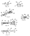
- FIG. 4 is a perspective view of a femoral positioner according to one embodiment of the invention.
- FIG. 5 is a top elevational view of the femoral positioner shown in FIG. 4.
- FIG. 6 is an enlarged cross-sectional view of a portion A in FIG. 5.
- FIG. 7 is a top elevational view of an augment in accordance with one embodiment of the invention.
- FIG. 8 is a side elevational view of the augment shown in FIG. 7.
- FIG. 9 is a perspective view of a spacer block in accordance with a further embodiment of the invention.
- FIG. 10 is a top elevational view of the spacer block shown in FIG. 9.
- FIG. 11 is a side elevational view of the spacer block illustrated in FIG. 9
- FIG. 12 is a cross-sectional view of the spacer block depicted in FIGS. 9 and 10 taken along line B-B.
-
- Referring to the drawings, which show a
femoral positioner 50 that can be used with a femoral resection guide, such as theguides positioner 50 includes asurface alignment plate 52 that is configured to rest on the resected surface R of the tibia, like thepositioner 26 shown in FIG. 2. Thealignment plate 52 defines aslot 54 that can engage a pin disposed within the medullary canal of the tibia (not shown) to align the plate with the resected tibial plateau in a known manner. - A
connector plate 56 is arranged parallel with thesurface alignment plate 52 and is configured to engage a mating feature in the resection guide. For instance, theconnector plate 56 can engage theslot 23 in the main body of theresection guide 20 shown in FIG. 2, or theslot 34 or other mating feature in theguide 32. A base 58 integrally spans between theplates bore 60 to receive an alignment rod (not shown) that can be used to check ligament tension during the instrumentation procedure. - The
femoral positioner 50 is used to position the femur relative to the resected end R of the tibia. When the femur is properly positioned, the resection guide can be mounted on the exposed end of the femur and the necessary cuts made at the proper location on the bone. While thepositioner 50 may be properly sized to achieve these results for some patients, the majority of the cases will require some augmentation for the surface alignment plate. In some cases, the necessary augmentation is simply to close the space between thealignment plate 52 and the posterior surface of the femur when the knee is flexed, as shown in FIG. 2. In other cases, the surface of either the femur or the tibia has surface defects that compromise the stable support of thefemoral positioner 50. - In either case, an augment, such as the augment 70 shown in FIGS. 7 and 8 may be necessary. The augment 70 includes a
mating surface 72 and anopposite surface 75. Themating surface 72 contacts thesurface alignment plate 52 of thepositioner 50, while theopposite surface 75 contacts the bone. In the most basic case, theopposite surface 75 is flat and parallel to themating surface 72. The thickness between these two surfaces can vary as necessary to fill the expected flexion/extension gap. Nominally,several augments 70 can be provided, each having different thicknesses. Where the augment 70 serves as a shim or spacer, the augment will normally be supported on the femoral-facing surface 62a of the positioner 50 (FIG. 6). - In other cases, the
surface 75 of the augment 70 can include contours, such as thecontours 76 shown in dashed lines. These contours are configured to match defects in the bone against which the augment bears. Where the defects are in the tibia, the augment will be mounted to the underside or the tibia-facing surface 62b of the positioner 50 (FIG. 6). Thecontours 76 fill the bone defects and ensure that themating surface 72 will be supported in a proper parallel orientation. - In order to facilitate mounting and removal of the augment 70 from the
positioner 50, means for removably coupling the components together are provided that incorporate a resilient member. In the preferred embodiment, thesurface alignment plate 52 is provided with a pair ofbores 64 on opposite sides of thenotch 54. The augment 70 includes a mating pair ofpins 74 that are sized to be received within a corresponding one of the bores. As shown in the detail of FIG. 6, each of the bores defines aninternal groove 66 configured to receive an elastomeric O-ring 68. Eachpin 74 is sized to pass through thebore 64 into frictional contact with the O-ring 68. The O-ring provides a tight elastomeric fit so that the pins are not easily dislodged from the bores during normal manipulation of thefemoral positioner 50. Each pin can be provided with a groove (not shown) to receive the O-ring when the pin is properly positioned within the bore. - In the preferred embodiment, the O-
ring groove 66 is offset toward the tibial surface 62b. Thebore 64 has a diameter on either side of thegroove 66 that provides a close running fit for thepin 74. The O-ring defines an inner diameter that is less than the diameter of the bore. Thus, the tip 74a of the pin can be tapered to facilitate being pushed through the O-ring 66. The base of thebore 64 at the tibial side can be provided with achamfer 65 to further facilitate placement of the pin into the bore from the underside of thefemoral positioner 50. - The augment 70 can also be used with a spacer block, such as the
spacer block 80 shown in FIGS. 9-12. Thespacer block 88 includes aspacer body 82 connected to ahandle 84. The block defines anotch 83 therein that serves the same function as thenotch 54 in thefemoral positioner 50 discussed above. Thehandle 84 defines a number ofangled bores 85 configured for receiving an alignment rod (not shown). Thespacer block 80 can be used in a conventional manner to verify the flexion and extension gaps when the resection guide is mounted to the femur, or after the femoral implant has been mounted on the finished distal end of the femur. - In order to accommodate a variety of joint anatomies, the
body 82 of the spacer block defines a pair ofbores 90 passing from thetibial surface 87 to thefemoral surface 88. The bores are sized to receive thepins 74 of an appropriate augment 70. In accordance with the invention, the bores are provided with O-ring grooves and O-rings to firmly hold the pins within the bores. - In one feature of the embodiment, the
bores 90 are provided with two grooves 92a, 92b and two O-rings 94a, 94b. One O-ring 94a is positioned near thefemoral surface 88 and the other O-ring 94b is positioned near thetibial surface 87. It is contemplated that thepins 74 of the augment 70 have a predetermined height from themating surface 72 that is calibrated to fit thebores 64 in thefemoral positioner 50. Since thesurface alignment plate 52 of the positioner is thinner than thebody 82 of thespacer block 80, the height of thepins 74 is less than the thickness of the spacer block. Consequently, in order to orient an O-ring in a location where they can fully engage the pins, two O-rings 94a, 94b are provided, with a corresponding one offset to each surface of the spacer block. - In an alternative feature, the
bore 90 can define alarger bore portion 90a and a smaller bore portion 90b. Thelarger portion 90a is adjacent thefemoral surface 88, while the smaller portion 90b opens at thetibial surface 87. - While the described embodiment uses O-rings to provide the temporary fixation of the augment, the O-rings can be replaced with other resiliently gripping components. For instance, a slitted membrane can span the
bores
Claims (10)
- A system for establishing a prosthetic gap between first and second bones at a joint comprising:an instrument for positioning within the gap between the first and second bones, said instrument having a first surface facing the first bone and a second surface facing the second bone, and defining at least one bore between said first and second surfaces; andan augment for filling the gap when coupled to said instrument, said augment including at least one pin sized to be received within said at least one bore with said augment in contact with either said first surface or said second surface.
- The system for establishing a prosthetic gap of claim 1, wherein said instrument is a femoral positioner that includes a surface alignment plate configured to engage the tibia and a connector plate configured to engage a femoral resection guide, said surface alignment plate defining said at least one bore.
- The system for establishing a prosthetic gap of claim 1, wherein said instrument is a spacer block having a spacer body and a handle projecting therefrom, said spacer block defining said at least one bore.
- The system for establishing a prosthetic gap of claim 1, wherein said bore includes a resilient member disposed therein, said resilient member configured to resiliently engage said pin when said pin extends through said bore.
- The system for establishing a prosthetic gap of claim 4, wherein said bore defines an internal groove, and said resilient member is an O-ring mounted within said groove.
- The system for establishing a prosthetic gap of claim 5, wherein:said bore defines a pair of internal grooves, one each adjacent each of said first and second surfaces; andfurther wherein said resilient member includes an O-ring mounted within each of said pair of grooves.
- The system for establishing a prosthetic gap of claim 1, wherein said augment includes a mating surface for contacting said instrument when said pin is within said bore, and an opposite surface that is substantially parallel to said first or second surface of said instrument.
- The system for establishing a prosthetic gap of claim 1, wherein said augment includes a mating surface for contacting said instrument when said pin is within said bore, and an opposite surface for contacting one of the first or second bones when said mating surface contacts said instrument, said opposite surface defining a contour substantially similar to the contour of the first or second bones.
- A system for establishing a prosthetic gap between first and second bones at a joint comprising:an instrument for positioning within the gap between the first and second bones;an augment for filling the gap when coupled to said instrument; andmeans for removably coupling said augment to said instrument including a resilient member disposed between said augment and said instrument.
- A system for establishing a prosthetic gap between first and second bones at a joint comprising:an instrument for positioning within the gap between the first and second bones, said instrument having a first surface facing the first bone and a second surface facing the second bone;an augment for filling the gap when coupled to said instrument; andmeans for engaging the augment to the instrument adjacent either said first surface or said second surface.
Applications Claiming Priority (2)
| Application Number | Priority Date | Filing Date | Title |
|---|---|---|---|
| US748449 | 1991-08-22 | ||
| US10/748,449 US8025663B2 (en) | 2003-12-30 | 2003-12-30 | Augments for surgical instruments |
Publications (1)
| Publication Number | Publication Date |
|---|---|
| EP1550416A1 true EP1550416A1 (en) | 2005-07-06 |
Family
ID=34574767
Family Applications (1)
| Application Number | Title | Priority Date | Filing Date |
|---|---|---|---|
| EP04258129A Withdrawn EP1550416A1 (en) | 2003-12-30 | 2004-12-24 | Instrument augments for filling a bone joint gap |
Country Status (4)
| Country | Link |
|---|---|
| US (1) | US8025663B2 (en) |
| EP (1) | EP1550416A1 (en) |
| JP (1) | JP4959132B2 (en) |
| AU (1) | AU2004242486B2 (en) |
Cited By (7)
| Publication number | Priority date | Publication date | Assignee | Title |
|---|---|---|---|---|
| US7766969B2 (en) | 2005-12-05 | 2010-08-03 | Zimmer, Inc. | Modular progressive implant for a joint articulation surface |
| US7881768B2 (en) | 1998-09-14 | 2011-02-01 | The Board Of Trustees Of The Leland Stanford Junior University | Assessing the condition of a joint and devising treatment |
| US8036729B2 (en) | 1998-09-14 | 2011-10-11 | The Board Of Trustees Of The Leland Stanford Junior University | Assessing the condition of a joint and devising treatment |
| US8265730B2 (en) | 1998-09-14 | 2012-09-11 | The Board Of Trustees Of The Leland Stanford Junior University | Assessing the condition of a joint and preventing damage |
| US9286686B2 (en) | 1998-09-14 | 2016-03-15 | The Board Of Trustees Of The Leland Stanford Junior University | Assessing the condition of a joint and assessing cartilage loss |
| EP2617376A4 (en) * | 2010-09-13 | 2017-09-20 | Nakashima Medical Co., Ltd. | Bone resection jig used in surgical operation to replace artificial knee joint |
| EP3821845A4 (en) * | 2018-07-10 | 2022-03-09 | Corentec Co., Ltd. | Gap gauge and unit capable of checking flexion gap prior to cutting of posterior femur |
Families Citing this family (12)
| Publication number | Priority date | Publication date | Assignee | Title |
|---|---|---|---|---|
| CA2764002A1 (en) * | 2009-05-29 | 2010-12-02 | Smith & Nephew, Inc. | Methods and apparatus for performing knee arthroplasty |
| US20110270327A1 (en) * | 2010-03-09 | 2011-11-03 | Vot, Llc | Implant guide and method of use |
| US8663234B2 (en) | 2011-08-01 | 2014-03-04 | Zimmer, Inc. | Combination ligament tensioner and alignment device |
| WO2013063386A1 (en) | 2011-10-27 | 2013-05-02 | Smith & Nephew, Inc. | Devices and methods for performing knee arthroplasty |
| CN104955421A (en) | 2012-10-18 | 2015-09-30 | 史密夫和内修有限公司 | Alignment devices and methods |
| US11291437B2 (en) | 2016-12-22 | 2022-04-05 | Orthosensor Inc. | Tilting surgical tensor to support at least one bone cut |
| US11266512B2 (en) | 2016-12-22 | 2022-03-08 | Orthosensor Inc. | Surgical apparatus to support installation of a prosthetic component and method therefore |
| US11284873B2 (en) | 2016-12-22 | 2022-03-29 | Orthosensor Inc. | Surgical tensor where each distraction mechanism is supported and aligned by at least two guide shafts |
| US11185425B2 (en) | 2016-12-22 | 2021-11-30 | Orthosensor Inc. | Surgical tensor configured to distribute loading through at least two pivot points |
| US11399818B2 (en) | 2016-12-22 | 2022-08-02 | Orthosensor Inc. | Surgical apparatus to support installation of a prosthetic component with reduced alignment error |
| US11344421B2 (en) | 2018-08-13 | 2022-05-31 | Smith & Nephew, Inc. | Methods and instrumentation for balancing of ligaments in flexion |
| KR20210051778A (en) | 2019-10-31 | 2021-05-10 | 현대자동차주식회사 | An electrolyte membrane containing catalytic metal with improved electrical insulating property and a method for preparation thereof |
Citations (10)
| Publication number | Priority date | Publication date | Assignee | Title |
|---|---|---|---|---|
| US4738254A (en) | 1981-12-31 | 1988-04-19 | Biomedical Engineering Trust | Positioner for surgical instruments |
| US5520695A (en) * | 1992-02-14 | 1996-05-28 | Johnson & Johnson Professional, Inc. | Instruments for use in knee replacement surgery |
| WO1997021389A1 (en) * | 1995-12-08 | 1997-06-19 | Wright Medical Technology, Inc. | Distal femoral resection and re-cut instrumentation |
| US5649929A (en) * | 1995-07-10 | 1997-07-22 | Callaway; George Hadley | Knee joint flexion-gap distraction device |
| WO1998025526A1 (en) * | 1996-12-10 | 1998-06-18 | Memento S.A. | Ancillary equipment for preparing the setting of a knee prosthesis |
| WO1999009900A1 (en) * | 1997-08-25 | 1999-03-04 | Depuy Orthopaedics, Inc. | Low friction saw slot |
| EP0919195A1 (en) * | 1997-11-28 | 1999-06-02 | Sulzer Orthopädie AG | Tool assembly for a prosthetic knee |
| US6056754A (en) * | 1994-09-02 | 2000-05-02 | Hudson Surgical Design, Inc. | Method and apparatus for patella resection and guide handle |
| US6458135B1 (en) * | 2001-02-02 | 2002-10-01 | Howmedica Osteonics Corp. | Femoral guide for implanting a femoral knee prosthesis and method |
| US6575980B1 (en) * | 1997-01-28 | 2003-06-10 | New York Society For The Ruptured And Crippled Maintaining The Hospital For Special Surgery | Method and apparatus for femoral resection |
Family Cites Families (26)
| Publication number | Priority date | Publication date | Assignee | Title |
|---|---|---|---|---|
| US2460470A (en) * | 1946-11-27 | 1949-02-01 | Rogers Samuel Perry | Holding tool |
| US4487203A (en) * | 1981-11-03 | 1984-12-11 | Androphy Gary W | Triplanar knee resection method |
| US4653488A (en) * | 1982-02-18 | 1987-03-31 | Howmedica, Inc. | Prosthetic knee implantation |
| US4721104A (en) * | 1985-12-02 | 1988-01-26 | Dow Corning Wright Corporation | Femoral surface shaping apparatus for posterior-stabilized knee implants |
| US5275603A (en) * | 1992-02-20 | 1994-01-04 | Wright Medical Technology, Inc. | Rotationally and angularly adjustable tibial cutting guide and method of use |
| CA2098081A1 (en) * | 1992-08-13 | 1994-02-14 | Terry L. Dietz | Alignment guide and method |
| US5464406A (en) * | 1992-12-09 | 1995-11-07 | Ritter; Merrill A. | Instrumentation for revision surgery |
| JP3121171B2 (en) * | 1993-03-30 | 2000-12-25 | ファナック株式会社 | Non-powered chuck for robot hand |
| US5425490A (en) * | 1994-01-18 | 1995-06-20 | Goble; E. Marlowe | Instrument with dual holding feature |
| US5540696A (en) * | 1995-01-06 | 1996-07-30 | Zimmer, Inc. | Instrumentation for use in orthopaedic surgery |
| US5609642A (en) * | 1995-02-15 | 1997-03-11 | Smith & Nephew Richards Inc. | Tibial trial prosthesis and bone preparation system |
| US5735904A (en) | 1995-07-05 | 1998-04-07 | Pappas; Michael J. | Spacer for establishng prosthetic gap and ligamentous tension |
| US5639113A (en) * | 1995-07-21 | 1997-06-17 | Textron Inc. | Mounting assembly for air bag |
| US5733290A (en) * | 1995-12-21 | 1998-03-31 | Johnson & Johnson Professional, Inc. | Quick-release tibial alignment handle |
| CA2193451C (en) * | 1995-12-21 | 2005-11-01 | Diana F. Mccue | Instrument system for knee prosthesis implantation with universal handle or slap hammer |
| US5653714A (en) * | 1996-02-22 | 1997-08-05 | Zimmer, Inc. | Dual slide cutting guide |
| US5931838A (en) * | 1997-01-28 | 1999-08-03 | Vito; Raymond P. | Fixation assembly for orthopedic applications |
| US5976147A (en) * | 1997-07-11 | 1999-11-02 | Johnson & Johnson Professional, Inc | Modular instrumentation for bone preparation and implant trial reduction of orthopedic implants |
| JPH11113940A (en) * | 1997-10-09 | 1999-04-27 | Tsunenori Takei | Resect-assisting utensil for knee joint |
| US6159215A (en) * | 1997-12-19 | 2000-12-12 | Depuy Acromed, Inc. | Insertion instruments and method for delivering a vertebral body spacer |
| US6022377A (en) * | 1998-01-20 | 2000-02-08 | Sulzer Orthopedics Inc. | Instrument for evaluating balance of knee joint |
| US6443991B1 (en) | 1998-09-21 | 2002-09-03 | Depuy Orthopaedics, Inc. | Posterior stabilized mobile bearing knee |
| US6478800B1 (en) * | 2000-05-08 | 2002-11-12 | Depuy Acromed, Inc. | Medical installation tool |
| AU2002235351A1 (en) * | 2001-01-26 | 2002-08-06 | Osteotech, Inc. | Implant insertion tool |
| GB0119541D0 (en) | 2001-08-10 | 2001-10-03 | Depuy Int Ltd | Guide for locating femur resection plane |
| US7935118B2 (en) * | 2002-06-21 | 2011-05-03 | Depuy Products, Inc. | Prosthesis removal cutting guide, cutting tool and method |
-
2003
- 2003-12-30 US US10/748,449 patent/US8025663B2/en not_active Expired - Fee Related
-
2004
- 2004-12-23 AU AU2004242486A patent/AU2004242486B2/en active Active
- 2004-12-24 EP EP04258129A patent/EP1550416A1/en not_active Withdrawn
- 2004-12-28 JP JP2004380767A patent/JP4959132B2/en active Active
Patent Citations (10)
| Publication number | Priority date | Publication date | Assignee | Title |
|---|---|---|---|---|
| US4738254A (en) | 1981-12-31 | 1988-04-19 | Biomedical Engineering Trust | Positioner for surgical instruments |
| US5520695A (en) * | 1992-02-14 | 1996-05-28 | Johnson & Johnson Professional, Inc. | Instruments for use in knee replacement surgery |
| US6056754A (en) * | 1994-09-02 | 2000-05-02 | Hudson Surgical Design, Inc. | Method and apparatus for patella resection and guide handle |
| US5649929A (en) * | 1995-07-10 | 1997-07-22 | Callaway; George Hadley | Knee joint flexion-gap distraction device |
| WO1997021389A1 (en) * | 1995-12-08 | 1997-06-19 | Wright Medical Technology, Inc. | Distal femoral resection and re-cut instrumentation |
| WO1998025526A1 (en) * | 1996-12-10 | 1998-06-18 | Memento S.A. | Ancillary equipment for preparing the setting of a knee prosthesis |
| US6575980B1 (en) * | 1997-01-28 | 2003-06-10 | New York Society For The Ruptured And Crippled Maintaining The Hospital For Special Surgery | Method and apparatus for femoral resection |
| WO1999009900A1 (en) * | 1997-08-25 | 1999-03-04 | Depuy Orthopaedics, Inc. | Low friction saw slot |
| EP0919195A1 (en) * | 1997-11-28 | 1999-06-02 | Sulzer Orthopädie AG | Tool assembly for a prosthetic knee |
| US6458135B1 (en) * | 2001-02-02 | 2002-10-01 | Howmedica Osteonics Corp. | Femoral guide for implanting a femoral knee prosthesis and method |
Cited By (11)
| Publication number | Priority date | Publication date | Assignee | Title |
|---|---|---|---|---|
| US7881768B2 (en) | 1998-09-14 | 2011-02-01 | The Board Of Trustees Of The Leland Stanford Junior University | Assessing the condition of a joint and devising treatment |
| US8036729B2 (en) | 1998-09-14 | 2011-10-11 | The Board Of Trustees Of The Leland Stanford Junior University | Assessing the condition of a joint and devising treatment |
| US8112142B2 (en) | 1998-09-14 | 2012-02-07 | The Board Of Trustees Of The Leland Stanford Junior University | Assessing the condition of a joint and devising treatment |
| USRE43282E1 (en) | 1998-09-14 | 2012-03-27 | The Board Of Trustees Of The Leland Stanford Junior University | Assessing the condition of a joint and devising treatment |
| US8265730B2 (en) | 1998-09-14 | 2012-09-11 | The Board Of Trustees Of The Leland Stanford Junior University | Assessing the condition of a joint and preventing damage |
| US8306601B2 (en) | 1998-09-14 | 2012-11-06 | The Board Of Trustees Of The Leland Stanford Junior University | Assessing the condition of a joint and devising treatment |
| US8862202B2 (en) | 1998-09-14 | 2014-10-14 | The Board Of Trustees Of The Leland Stanford Junior University | Assessing the condition of a joint and preventing damage |
| US9286686B2 (en) | 1998-09-14 | 2016-03-15 | The Board Of Trustees Of The Leland Stanford Junior University | Assessing the condition of a joint and assessing cartilage loss |
| US7766969B2 (en) | 2005-12-05 | 2010-08-03 | Zimmer, Inc. | Modular progressive implant for a joint articulation surface |
| EP2617376A4 (en) * | 2010-09-13 | 2017-09-20 | Nakashima Medical Co., Ltd. | Bone resection jig used in surgical operation to replace artificial knee joint |
| EP3821845A4 (en) * | 2018-07-10 | 2022-03-09 | Corentec Co., Ltd. | Gap gauge and unit capable of checking flexion gap prior to cutting of posterior femur |
Also Published As
| Publication number | Publication date |
|---|---|
| AU2004242486B2 (en) | 2010-04-29 |
| US20050143744A1 (en) | 2005-06-30 |
| JP2005193048A (en) | 2005-07-21 |
| AU2004242486A1 (en) | 2005-07-14 |
| US8025663B2 (en) | 2011-09-27 |
| JP4959132B2 (en) | 2012-06-20 |
Similar Documents
| Publication | Publication Date | Title |
|---|---|---|
| US8025663B2 (en) | Augments for surgical instruments | |
| AU2009213053B2 (en) | Instruments and methods for flexion gap adjustment | |
| US20190046215A1 (en) | Instruments and methods in performing kinematically-aligned total knee arthroplasty | |
| EP0754439B1 (en) | Spacer for establishing prosthetic gap and ligamentous tension | |
| US5879354A (en) | Prosthetic implant | |
| US8663234B2 (en) | Combination ligament tensioner and alignment device | |
| US7686812B2 (en) | Method for setting the rotational position of a femoral component | |
| CA2571322C (en) | Systems and processes for determining proper superior-inferior joint line positioning | |
| US20140156019A1 (en) | Prosthesis and implementation system | |
| US20060015113A1 (en) | Optimizing patellar femoral mechanics through alternative depth referencing | |
| JPH0548699B2 (en) | ||
| US20130310841A1 (en) | Femoral Sizing Devices and Procedures for Use in Knee Surgery | |
| US20230285032A1 (en) | Surgical instrument | |
| CN112367940A (en) | Clearance gauge and unit capable of confirming flexion clearance before femoral rear end resection | |
| WO2006112911A2 (en) | Unicondylar knee implant and instrument system | |
| US20240016628A1 (en) | Spacer blocks, systems and methods for trialing knee joint | |
| US20230165683A1 (en) | Hinge Knee Assembly Guide | |
| US20190298536A1 (en) | Modular Gap Balancing Block | |
| Bonnin et al. | Unicompartmental knee arthroplasty—Technical principles |
Legal Events
| Date | Code | Title | Description |
|---|---|---|---|
| PUAI | Public reference made under article 153(3) epc to a published international application that has entered the european phase |
Free format text: ORIGINAL CODE: 0009012 |
|
| AK | Designated contracting states |
Kind code of ref document: A1 Designated state(s): AT BE BG CH CY CZ DE DK EE ES FI FR GB GR HU IE IS IT LI LT LU MC NL PL PT RO SE SI SK TR |
|
| AX | Request for extension of the european patent |
Extension state: AL BA HR LV MK YU |
|
| 17P | Request for examination filed |
Effective date: 20050720 |
|
| AKX | Designation fees paid |
Designated state(s): AT BE BG CH CY CZ DE DK EE ES FI FR GB GR HU IE IS IT LI LT LU MC NL PL PT RO SE SI SK TR |
|
| 17Q | First examination report despatched |
Effective date: 20070423 |
|
| STAA | Information on the status of an ep patent application or granted ep patent |
Free format text: STATUS: THE APPLICATION IS DEEMED TO BE WITHDRAWN |
|
| 18D | Application deemed to be withdrawn |
Effective date: 20150107 |