EP1550883A2 - Apparatus and method for displaying sectional planes of target object utilizing 3-dimensional ultrasound data - Google Patents
Apparatus and method for displaying sectional planes of target object utilizing 3-dimensional ultrasound data Download PDFInfo
- Publication number
- EP1550883A2 EP1550883A2 EP04030404A EP04030404A EP1550883A2 EP 1550883 A2 EP1550883 A2 EP 1550883A2 EP 04030404 A EP04030404 A EP 04030404A EP 04030404 A EP04030404 A EP 04030404A EP 1550883 A2 EP1550883 A2 EP 1550883A2
- Authority
- EP
- European Patent Office
- Prior art keywords
- data
- sectional plane
- target object
- image
- coordinates
- Prior art date
- Legal status (The legal status is an assumption and is not a legal conclusion. Google has not performed a legal analysis and makes no representation as to the accuracy of the status listed.)
- Granted
Links
Images


Classifications
-
- A—HUMAN NECESSITIES
- A61—MEDICAL OR VETERINARY SCIENCE; HYGIENE
- A61B—DIAGNOSIS; SURGERY; IDENTIFICATION
- A61B8/00—Diagnosis using ultrasonic, sonic or infrasonic waves
- A61B8/13—Tomography
-
- G—PHYSICS
- G06—COMPUTING; CALCULATING OR COUNTING
- G06T—IMAGE DATA PROCESSING OR GENERATION, IN GENERAL
- G06T19/00—Manipulating 3D models or images for computer graphics
-
- A—HUMAN NECESSITIES
- A61—MEDICAL OR VETERINARY SCIENCE; HYGIENE
- A61B—DIAGNOSIS; SURGERY; IDENTIFICATION
- A61B8/00—Diagnosis using ultrasonic, sonic or infrasonic waves
- A61B8/46—Ultrasonic, sonic or infrasonic diagnostic devices with special arrangements for interfacing with the operator or the patient
- A61B8/461—Displaying means of special interest
- A61B8/463—Displaying means of special interest characterised by displaying multiple images or images and diagnostic data on one display
-
- A—HUMAN NECESSITIES
- A61—MEDICAL OR VETERINARY SCIENCE; HYGIENE
- A61B—DIAGNOSIS; SURGERY; IDENTIFICATION
- A61B8/00—Diagnosis using ultrasonic, sonic or infrasonic waves
- A61B8/48—Diagnostic techniques
- A61B8/483—Diagnostic techniques involving the acquisition of a 3D volume of data
-
- A—HUMAN NECESSITIES
- A61—MEDICAL OR VETERINARY SCIENCE; HYGIENE
- A61B—DIAGNOSIS; SURGERY; IDENTIFICATION
- A61B8/00—Diagnosis using ultrasonic, sonic or infrasonic waves
- A61B8/52—Devices using data or image processing specially adapted for diagnosis using ultrasonic, sonic or infrasonic waves
- A61B8/5215—Devices using data or image processing specially adapted for diagnosis using ultrasonic, sonic or infrasonic waves involving processing of medical diagnostic data
- A61B8/523—Devices using data or image processing specially adapted for diagnosis using ultrasonic, sonic or infrasonic waves involving processing of medical diagnostic data for generating planar views from image data in a user selectable plane not corresponding to the acquisition plane
-
- G—PHYSICS
- G01—MEASURING; TESTING
- G01S—RADIO DIRECTION-FINDING; RADIO NAVIGATION; DETERMINING DISTANCE OR VELOCITY BY USE OF RADIO WAVES; LOCATING OR PRESENCE-DETECTING BY USE OF THE REFLECTION OR RERADIATION OF RADIO WAVES; ANALOGOUS ARRANGEMENTS USING OTHER WAVES
- G01S15/00—Systems using the reflection or reradiation of acoustic waves, e.g. sonar systems
- G01S15/88—Sonar systems specially adapted for specific applications
- G01S15/89—Sonar systems specially adapted for specific applications for mapping or imaging
- G01S15/8906—Short-range imaging systems; Acoustic microscope systems using pulse-echo techniques
- G01S15/8993—Three dimensional imaging systems
-
- G—PHYSICS
- G01—MEASURING; TESTING
- G01S—RADIO DIRECTION-FINDING; RADIO NAVIGATION; DETERMINING DISTANCE OR VELOCITY BY USE OF RADIO WAVES; LOCATING OR PRESENCE-DETECTING BY USE OF THE REFLECTION OR RERADIATION OF RADIO WAVES; ANALOGOUS ARRANGEMENTS USING OTHER WAVES
- G01S7/00—Details of systems according to groups G01S13/00, G01S15/00, G01S17/00
- G01S7/52—Details of systems according to groups G01S13/00, G01S15/00, G01S17/00 of systems according to group G01S15/00
- G01S7/52017—Details of systems according to groups G01S13/00, G01S15/00, G01S17/00 of systems according to group G01S15/00 particularly adapted to short-range imaging
- G01S7/52023—Details of receivers
- G01S7/52044—Scan converters
-
- G—PHYSICS
- G01—MEASURING; TESTING
- G01S—RADIO DIRECTION-FINDING; RADIO NAVIGATION; DETERMINING DISTANCE OR VELOCITY BY USE OF RADIO WAVES; LOCATING OR PRESENCE-DETECTING BY USE OF THE REFLECTION OR RERADIATION OF RADIO WAVES; ANALOGOUS ARRANGEMENTS USING OTHER WAVES
- G01S7/00—Details of systems according to groups G01S13/00, G01S15/00, G01S17/00
- G01S7/52—Details of systems according to groups G01S13/00, G01S15/00, G01S17/00 of systems according to group G01S15/00
- G01S7/52017—Details of systems according to groups G01S13/00, G01S15/00, G01S17/00 of systems according to group G01S15/00 particularly adapted to short-range imaging
- G01S7/52053—Display arrangements
- G01S7/52057—Cathode ray tube displays
- G01S7/5206—Two-dimensional coordinated display of distance and direction; B-scan display
- G01S7/52063—Sector scan display
-
- G—PHYSICS
- G01—MEASURING; TESTING
- G01S—RADIO DIRECTION-FINDING; RADIO NAVIGATION; DETERMINING DISTANCE OR VELOCITY BY USE OF RADIO WAVES; LOCATING OR PRESENCE-DETECTING BY USE OF THE REFLECTION OR RERADIATION OF RADIO WAVES; ANALOGOUS ARRANGEMENTS USING OTHER WAVES
- G01S7/00—Details of systems according to groups G01S13/00, G01S15/00, G01S17/00
- G01S7/52—Details of systems according to groups G01S13/00, G01S15/00, G01S17/00 of systems according to group G01S15/00
- G01S7/52017—Details of systems according to groups G01S13/00, G01S15/00, G01S17/00 of systems according to group G01S15/00 particularly adapted to short-range imaging
- G01S7/52053—Display arrangements
- G01S7/52057—Cathode ray tube displays
- G01S7/52074—Composite displays, e.g. split-screen displays; Combination of multiple images or of images and alphanumeric tabular information
-
- G—PHYSICS
- G01—MEASURING; TESTING
- G01S—RADIO DIRECTION-FINDING; RADIO NAVIGATION; DETERMINING DISTANCE OR VELOCITY BY USE OF RADIO WAVES; LOCATING OR PRESENCE-DETECTING BY USE OF THE REFLECTION OR RERADIATION OF RADIO WAVES; ANALOGOUS ARRANGEMENTS USING OTHER WAVES
- G01S7/00—Details of systems according to groups G01S13/00, G01S15/00, G01S17/00
- G01S7/52—Details of systems according to groups G01S13/00, G01S15/00, G01S17/00 of systems according to group G01S15/00
- G01S7/52017—Details of systems according to groups G01S13/00, G01S15/00, G01S17/00 of systems according to group G01S15/00 particularly adapted to short-range imaging
- G01S7/52053—Display arrangements
- G01S7/52057—Cathode ray tube displays
- G01S7/52073—Production of cursor lines, markers or indicia by electronic means
-
- G—PHYSICS
- G06—COMPUTING; CALCULATING OR COUNTING
- G06T—IMAGE DATA PROCESSING OR GENERATION, IN GENERAL
- G06T2219/00—Indexing scheme for manipulating 3D models or images for computer graphics
- G06T2219/008—Cut plane or projection plane definition
Definitions
- the present invention relates to an apparatus and method for displaying sectional planes of a target object utilizing 3-dimensional (3D) ultrasound data. More particularly, the present invention relates to an apparatus and method for displaying sectional planes of a target object utilizing 3D ultrasound data in order to display the target object in real time.
- a 3D ultrasound diagnostic device acquires the 3D ultrasound data of a target object by using a probe.
- the 3D ultrasound diagnostic device displays a 3D image of the target object on a screen of a display device by converting conical coordinates of the acquired data to Cartesian coordinates suitable for display (scan conversion).
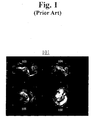
- An Image area of the target object displayed on the screen of a display device through the scan conversion and rendering is called a "view.”
- An example of the view is illustrated in Fig. 1.
- the view 101 includes: a 3D ultrasound image 102 of the target object; a 2D ultrasound image 103 for an A sectional plane representing a front side of the 3D ultrasound image 103; a 2D ultrasound image 104 for a B sectional plane representing a lateral side of the 3D ultrasound image 103; and a 2D ultrasound image 105 for a C sectional plane representing a top side of the 3D ultrasound image 102.
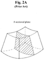
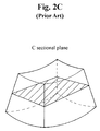
- Figs. 2A to 2C show the A, B and C sectional planes in a 3D ultrasound image for the target object.
- a solid line represents the target object and dashed planes represent the A, B and C sectional planes in Figs. 2A, 2B and 2C, respectively.
- the conventional 3D ultrasound diagnostic device mentioned above has the following problems.
- the conventional 3D ultrasound diagnostic device has the problem in that a prolonged time is required to perform a conversion process of the 3D data in order to obtain a desired type from the 3D data.
- the acquired data are not stored as 3D data according to the conventional ultrasound diagnostic device, a problem exists in that the 3D information of the target object should be acquired whenever the target object is diagnosed.
- the conventional ultrasound diagnostic device directly displays an image of information related to organs of a patient on a monitor or the like.
- the patient can be diagnosed and the condition of the patient can be analyzed only when the patient is present. That is, since the 3D data acquired from the target object are not stored, when the patient is not present, a clinical diagnosis can be performed based on just a past diagnosis picture or calling the patient again later.
- the conventional 3D ultrasound device does not provide images of the 3D sectional planes (e.g. coronal, sagital or axial plane) that is sufficient for diagnosis.
- the 3D ultrasound diagnostic device has been used to satisfy human curiosity rather than for a substantial medical examination of the patient by using the 3D ultrasound data.
- the conventional 3D ultrasound diagnostic device has been focused to 3-dimensionally displaying the target object instead of displaying the sectional planes necessary to examine the patient. Even if the conventional 3D ultrasound diagnostic device displays the image of the sectional planes, that image is only for 3D image of the target object and a specific image of the A, B or C sectional plane is merely displayed.
- an apparatus displaying a target object by using 3D ultrasound data including: a scan conversion unit for performing scan conversion to convert conical coordinates of 3D data to Cartesian coordinates for display on a screen of a display device; and a rendering unit for rendering multiple sectional plane images, which are based on the scan-converted 3D data, parallel with a reference sectional plane.
- a method for displaying a target object by using 3D ultrasound data including the steps of: storing indices matched with Cartesian coordinate of a screen in a display device to display a 3D image of the target object and operation resulting values of operations to convert Cartesian coordinates to conical coordinates coordinate in a geometric look-up table storage unit; receiving reference sectional plane information from an interface device, receiving 3D data of the target object from a probe or a 3D data storage device, and determining whether a current display region displaying an ultrasound image based on the 3D data of the target object is different from a previous display region on the screen; calculating the display region to display the image on the screen when the display region is changed; scan-converting 3D data of the target object by retrieving the operation resulting values from the geometric look-up table storage unit in order to convert Cartesian coordinates to conical coordinates corresponding to the calculated display region; and rendering multiple sectional plane images based on the scan-converted 3D data,
- a method for displaying slice images of a target object by using 3D ultrasound data including the steps of: setting a reference sectional plane of the target object to be displayed; acquiring the 3D ultrasound data of the target object; displaying the reference sectional plane image; drawing a line on the displayed reference sectional plane for displaying a desired oblique sectional plane; and displaying the desired oblique sectional plane perpendicular to the reference sectional plane taken along the line by using an anti-aliasing method.
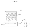
- Fig. 3A is a diagram illustrating a real-time ultrasound diagnostic system 300 in accordance with the preferred embodiment of the present invention.
- the real-time ultrasound diagnostic system 300 includes a probe 301, a display device 303 and a body 302.
- the probe 301 is used to acquire 3D data of a target object to be displayed.
- a mechanical scanning process (scan by moving a mechanical arm or rotating a stepping motor) or a hand-free process (scan by a user's hand) may be applied to the probe 301.
- the display device 303 e.g., a monitor
- any type of display device could be used.
- the body 302 processes the 3D data acquired from the probe 301 to be displayed on a display region of the display device 303. Then, the data processing is carried out in a rendering device for a 3D ultrasound diagnostic system included in the body 302. Hereinafter, the rendering device for the 3D ultrasound diagnostic system will be described.
- Fig. 3B is a block diagram illustrating the rendering device 310 for the 3D ultrasound diagnostic system in accordance with the preferred embodiment of the present invention.
- the rendering device 310 for the 3D ultrasound diagnostic system 300 includes an interface device 318, a determination unit 312, a display region calculation unit 131, a scan conversion unit 314, a geometric look-up table storage unit 311, a rendering look-up table storage unit 315, a rendering unit 316 and a data storing device 317.
- the interface device 318 receives a view operation command, which is inputted from a user or is automatically set.
- the view operation command essentially commands how to display and process the 3D data acquired from the probe 301 and then outputs after appropriately converting the commands.
- the view operation command may include commands related to a reference sectional plane of the target object to be displayed, a screen layout, a display region and the like. The operation of the interface device 318 for the above commands will be described.
- the interface device 318 receives the information of a reference sectional plane from the user. It then outputs a command so that a plurality of sectional planes of the target object parallel with the reference sectional plane is displayed in a vertical direction to the reference sectional plane
- the reference sectional plane is selectively determined from one of the sectional planes corresponding to the A, B and C sectional planes by the user.
- the interface device 318 receives the information of the screen layout from the user and then outputs a command so that the sectional plane images are displayed according to the information.
- the screen layout which is a configuration figure representing how many sectional plane images are displayed on the screen of the display device 303, can be automatically determined according the number of the sectional plane images of the target object to be displayed.
- the interface device 318 receives the information of the display region from the user and outputs a command so that an image corresponding to the display region is displayed only on the screen of the display device.
- the display region which indicates the size of an image of the target object to be displayed on the screen of the display device, can be set directly on the display device 303 or by inputting coordinates through a mouse or the like by the user. According to the above configuration, since the scan conversion of the 3D ultrasound data of the target object corresponding to a region, which is not substantially displayed, is not required, a data processing speed can be improved. A detailed description will be mentioned later.
- the determination unit 312 determines whether the 3D data of the target object is received from the probe. Or, the 3D data storage device 317 in accordance with that of the display region is changed on the basis of the information of the display region from the interface device 318. More particularly, if it is required that a current image of the target object has to be displayed in real time whenever the probe acquires the data of the target object, the 3D data is received from the probe 301. If it is required that the scan is virtually performed by using the data stored beforehand, the 3D data of the target object is received from the data storage device 317, which will be described later.
- the display region is changed when the user enlarges the display region or the displayed 3D image becomes rotated, moved or expanded. Even if the display region is not changed when the target object is first scanned, it can be determined that the display region may be changed.
- the determination unit 312 when the display region is changed, the determination unit 312 outputs the information related to the 3D data of the target object and the display region to the display region calculation unit 313. When the display region is not changed, the determination unit 312 outputs the information related to the 3D data of the target object and the display region to the rendering look-up table storage unit 315. A case outputted to the rendering look-up table storage unit 315 will be described later.
- the display region calculation unit 313 calculates Cartesian coordinates of x, y and z in the displayed region in which the ultrasound images 102 to 105 as the view 101 illustrated in Fig. 1 are substantially displayed.
- the display region calculation unit 313 outputs the 3D data of the target object received through the determination unit 312 without any special process.
- the scan conversion unit 314 receives conical coordinates of the 3D data of the target object and the Cartesian coordinates of the x, y and z calculated in the display region calculation unit 313. It then converts the Cartesian coordinates to the conical coordinates of the 3D data of the target object based on the Cartesian coordinates of x, y and z (Scan Conversion).
- the reason for converting the data is because the 3D ultrasound data received from the probe 301 is not based on the Cartesian coordinates but rather based on the conical coordinates.
- the display region displayed on the display device is based on the Cartesian coordinates.
- a complicated mathematical operation such as an arc tangent operation should be carried out. Whenever the 3D data of the target object is received, if the arc tangent operation is carried out, it requires a long operation time. Therefore, the target object cannot be displayed in real time.
- a geometric look-up table which stores indices matched with the 3D Cartesian coordinates of the screen and arc tangent operation resulting values corresponding to each index of 3D data.
- the geometric look-up table is stored in the geometric look-up table storage unit 311.
- the Cartesian coordinates of the display region can be rapidly scan converted to the conical coordinates of the 3D data of the target object for a 3D rendering process. This is so that the image of the target object can be displayed in real time.
- the geometric look-up table should be produced before the 3D data of the target object is received from the probe 301 in accordance with the present invention.
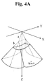
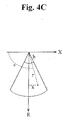
- Fig. 4A is a diagram showing the relation between the conical coordinates and the Cartesian coordinates.
- Fig. 4B is a diagram illustrating an arbitrary 3D data shown in Fig. 4A in a Y-Z Cartesian coordinates.
- Fig. 4C is a diagram illustrating an arbitrary 3D data shown in Fig. 4A in a X-R Cartesian coordinates.
- the axes of X, Y and Z are to configure a 3D Cartesian coordinates in which the image of the target object can be displayed.
- R axis is an axis perpendicular to the X axis from a portion in which the 3D ultrasound image is acquired.
- ⁇ represents a scan viewing angle, which corresponds to a swing angle range of a stepping motor in the probe, ranging from 0° to 180°;
- ⁇ represents a probe viewing angle, which corresponds to a width angle range of a 2D image scanned from the probe 301, ranging from 0° to 180°;
- r represents a distance from a portion in which the ultrasound image is acquired to an arbitrary 3D data;
- a represents a distance from an angular point of the scan viewing angle to an angular point of the probe viewing angle;
- b represents a distance from an angular point of the probe viewing point to the portion in which the ultrasound image is acquired.
- x, y and z represent the overall values of X, Y and Z axes.
- Equation 1 In order to obtain the conical coordinates of ⁇ and ⁇ from Equation 1, the arc tangent operations of tan -1 ( y / z ) and tan -1 ( x / R ) have to be first performed.
- the x, y and z in the arc tangent equation are set values corresponding to the Cartesian coordinates of the screen of the display device.
- R is calculated from the x, y and z as shown in Equation 1.
- the following tables 1A and 1B show calculations of R and r.
- r is calculated by performing a parallel processing for arbitrary 4 numbers of z existing in the X axis and r.
- m1 [y4, y3, y2, y1]
- Input y to m1 m5 m1 x [y4, y3, y2, y1]
- Input z to m2 m6 m2 x [z4, z3, z2, z1]
- m0 [x4, x3, x2, x1]
- Input x to m0 m4 m0 x [x4, x3, x2, x1]
- m4 is a
- the geometric look-up table includes:
- the scan conversion unit 314 retrieves the index matched with the 3D conical coordinates and the resulting values of the arc tangent operations corresponding to the index by using the geometric look-up table stored in the geometric look-up table storage unit 311, which is previously produced.
- the retrieved resulting value of the arc tangent operation is applied to the Equation 1, the conical coordinates of ( ⁇ , ⁇ 1, r1), ( ⁇ 2, ⁇ 2, r2), ... , ( ⁇ n, ⁇ n, m) corresponding to the coordinates of (x1, y1, z1), (x2, y2, z2), ... , (xn, yn, zn) can be acquired.
- the scan conversion unit 314 converts the Cartesian coordinates of display region to the conical coordinates of the 3D data. It then outputs the converted 3D data, the conical coordinates in which the 3D data are located and the index retrieved from the geometric look-up table storage unit 311.
- the scan conversion unit 314 performs the scan conversion after finding the conical coordinates in which the 3D data of the target object are located. This can be done by performing the parallel processing of the x, y, z and R, which are previously set, by using the resulting values of the arc tangent operation included in the geometric look-up table storage unit 311 (instead of directly performing the arc tangent operation requiring a long operation time).
- the speed for scan-converting the Cartesian coordinates of the display region to the conical coordinates of the 3D data of target object can be improved.
- the rendering look-up table storage unit 315 receives the data from the scan conversion unit 314 if the determination unit 312 determines that the display region is changed (and from the determination unit 312). In case of receiving the data from the scan conversion unit 314, the index and the conical coordinates corresponding to the 3D data are received. Then, a rendering look-up table including the received index and the conical coordinates is produced and stored. Thereafter, the scan-converted 3D data are outputted.
- the reason for producing and storing the rendering look-up table is as follows.
- the Cartesain coordinates corresponding to the previous display region are retrieved. Then, the conical coordinates of the 3D data corresponding to the Cartesian coordinates are outputted.
- the conical coordinates of the 3D data of a new target object which are scan-converted from the Cartesian coordinates of the display region, are identically located with the Cartesian coordinates of the display region of the prior target object.
- the 3D data of a first target object located in the conical coordinates of ( ⁇ n, ⁇ n, m) and the 3D data of a second target object located in the conical coordinates of ( ⁇ n, ⁇ n, m) are scan-converted from identical Cartesian coordinate values of (xn, yn, zn) of display region (even if the target object is changed)
- the indices matched with the conical coordinates of the 3D data are identical to each other. As such, it is not required to pass the display region calculation unit 313 and the scan conversion unit 314.
- an operation frequently changing the display region such as continuous movement or enlargement of the displayed image can be performed. Since performing the scan conversion together with generating and storing the rendering look-up table at each time can give more loads to the system, the data can be transmitted from the scan conversion unit 314 and the rendering unit 316 without producing the rendering look-up table in the rendering look-up table storage unit 315.
- the rendering unit 316 renders as many as the number of layouts selected by the interface device 318 by using the 3D data of the target object received from the rendering look-up table storage unit 315 and the scan conversion unit 314.
- the rendering unit 316 displays an image of multiple sectional planes of the target object by projecting the received 3D data to the 3D coordinates of the display region. If the image is exceeded over one screen because the number of the sectional planes of the layout is too many, the image of the next sectional plane can be shown by using a scroll function of the windows or the like.
- the multiple sectional planes are the plurality of sectional planes of the target object parallel with a reference sectional plane in the vertical direction of the reference sectional plane
- a process for rendering the 3D data is carried out identical to the direct volume rendering process, which is typically used. As such, a detailed explanation will be omitted herein.
- the multiple sectional planes can be displayed according to a distance from the reference sectional plane If necessary, the multiple sectional planes can be displayed according to an absolute depth from a surface of the target object. Also, the user can adjust the distance between the sectional planes through the interface device. This is so that the diagnosis can be carried out by showing the sectional plane images for a more minute depth.
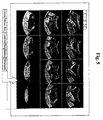
- Fig. 5 is a photograph showing ultrasound images of the multiple sectional planes displayed after performing the rendering.
- B and C represent the reference sectional planes of the A, B and C sectional planes, respectively.
- the displayed images are changed by which one of the reference sectional planes is selected by the user.
- various view operation commands which process the displayed image, are denoted at the bottom portion. The user can zoom in/out, delete or move the displayed image (as the image is edited in a picture plate of the Windows) by using the view operation commands.
- the user can find the desired image by moving the probe showing the displayed multiple sectional plane images.
- the sectional plane image of the target object is displayed in real time.
- the real-time status is stopped and the 3D data can be stored in the data storage device 317. Therefore, even if the target object does not exist afterwards, the target object can be virtually scanned by using the stored data.
- the determination unit 312 receives the 3D data of the target object from the 3D data storage device 317. If it is requested to display the current sectional plane images of the target image by acquiring the 3D data of the target object in real time, the determination unit 312 receives the 3D data of the target object from the probe 301. If it is requested to virtually scan the target object by using the previously stored data, the 3D data of the target object are received from the 3D data storage device 317.
- the 3D data storage device 317 may include various volatile storage devices and/or non-volatile storage devices.
- the non-volatile storage device may include a read only memory (ROM), a programmable read only memory (PROM), an electrically programmable read only memory (EPROM) and an electrically erasable programmable read only memory.
- the volatile storage device may include a random access memory (RAM), a synchronous RAM (SRAM), a dynamic RAM (DRAM), a synchronous DRAM (SDRAM), a double data rate SDRAM (DDR SDRAM) and a direct RAM bus (DRRAM).
- RAM random access memory
- SRAM synchronous RAM
- DRAM dynamic RAM
- SDRAM synchronous DRAM
- DDR SDRAM double data rate SDRAM
- DRRAM direct RAM bus
- a memory device such as a magnetic disk drive, a floppy disk drive, a tape drive, a Zip drive, a flash memory card, a memory stick, compact disk ROM (CD-ROM), a CD recordable drive (CD-R), a CD rewriteable drive (CD-RW drive), a digital versatile ROM drive (DVD ROM) or the like.
- a memory device such as a magnetic disk drive, a floppy disk drive, a tape drive, a Zip drive, a flash memory card, a memory stick, compact disk ROM (CD-ROM), a CD recordable drive (CD-R), a CD rewriteable drive (CD-RW drive), a digital versatile ROM drive (DVD ROM) or the like.
- CD-ROM compact disk ROM
- CD-R CD recordable drive
- CD-RW drive CD rewriteable drive
- DVD ROM digital versatile ROM drive
- the storage device is not limited only to the above storage devices.
- the user can display the multiple sectional plane images by using the stored 3D data, that is, through the virtual scan. Since the procedure processing the 3D data of the target object received from the 3D data storage device 317 is identical to the procedure processing the 3D data of the target object received from the probe 301, a detailed explanation will be omitted herein.
- the number of the layouts to be displayed is equal to the number of the layouts used in acquiring the 3D data.
- the number of the layouts means the number of sectional planes that the user wants to see. As such, if the user intends to see an image of different sectional plane or different depth from the stored data, the required data can be generated and rendered by using an interpolation or the like.
- An oblique sectional plane view which will be described later, can be applied to the displayed image.
- the data can be used to the next operation by storing the final result.
- the movement, enlargement or reduction in the image of the multiple sectional planes can be implemented through an image processing technique without performing the process (as described in Fig. 3B) for improving the processing speed.
- the user can identify a set of sectional plane images representing different locations for each scan direction at once in real time by using the multiple sectional plane images. This is so that the diagnosis can be rapidly and accurately implemented.
- the user can better accurately determine whether a displayed portion corresponds to the desired data.
- An ultrasound diagnostic system scans the target object by moving the probe with a hand's movement. It is possible that an inaccurate location is scanned due to the hand's movement.
- the user can identify the desired image through the real-time multiple sectional plane images and accurately perform the diagnosis through various image processes again in the multiple sectional plane images of a static state by storing the desired volume data.
- the multiple sectional plane views can be displayed the same as the target object exists and the oblique sectional plane view can be displayed.
- the operator can perform various image processes for the displayed image and the oblique sectional plane view function. This is so that the desired image can be more freely displayed.
- the conventional 3D ultrasound diagnostic system displays A sectional plane, B sectional plane and C sectional plane, which perpendicularly section an image of the 3D data at a specific location as illustrated in Fig. 1 and shows an arbitrary sectional plane through rotation of the displayed sectional plane
- the sectional plane desired to be seen by the user cannot be freely displayed.
- the present invention provides the oblique sectional plane view function capable of making the desired sectional plane to be directly seen at an image of a reference sectional plane by the user.
- the user draws an arbitrary straight line or curved line on the reference sectional plane. Then, a plane or a curved surface extended in a vertical direction of the reference sectional plane from the drawn straight line or curved line will be finally displayed in accordance with the oblique sectional plane image display method of the present invention.
- the selectable sectional plane image can be displayed by using a conventional 3D data acquisition method (not the above real-time method) and the 3D data, which have been already stored in the storage medium.
- the user determines whether the arbitrary line is represented with the straight line (line mode) or the curved line (contour mode) at the step 602.
- the reason why one line of the straight and curved lines is selected is because an anti-alias method can be different according to each line.
- the coordinates of a mouse pointer at that time is stored in a buffer at step 603.
- the mouse is used as an example to draw the arbitrary line.
- another input device such as a touch pad or the like, can be used instead of the mouse.
- a line processing is performed. If the line type is the curved line, it is moved to a step processing the mouse movement at step 604. In order to display the straight line, start coordinates and end coordinates of the mouse pointer are only required. On the other hand, in order to display the curved line, the overall coordinates are required in moving the mouse. Thus, the processes are different from each other.
- the line mode indicating the straight line is on standby until a mouse up event generated when a click button of the mouse is released is generated.
- the overall coordinates in moving the mouse are continuously stored in a buffer (hereinafter, referred to as an oblique buffer) at the step 605.
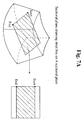
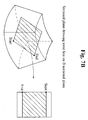
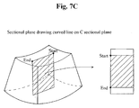
- a desired sectional plane in the displayed A sectional plane is indicated (as shown in Fig. 7A).
- a starting point is a point that the user starts to draw the line and an ending point is a point that the user ends to draw the line (as shown in Fig. 7A).
- a dashed region is displayed after an anti-aliasing process is performed.
- Figs. 7B and 7C show the Band C sectional planes.
- Fig. 7D shows the sectional plane obtained by drawing the curved lines (as illustrated in Fig. 7A) on the A sectional plane.
- the lines are not consecutively drawn. Also, since the image information of the monitor screen is represented through 2-dimensionally arrayed dots, if the dots are of the small number, the lines may not be smooth due to a jagged staircase effect. As shown in Fig. 8A, even though the user tries to represent the straight line in a horizontal direction of the reference sectional plan, the user may not see the straight line but the dashed region due to the aliasing phenomenon. Figs.
- An anti-aliasing method which is introduced for solving the above problem, is an image processing technique smoothly representing the image by adding dots of an intermediate color of the background and the line between each dot.
- a selective anti-aliasing technique can be employed instead of the general anti-aliasing technique in accordance with the present invention.
- the selective anti-aliasing technique is not to apply the anti-aliasing technique to the overall segment data of the lines but to apply the anti-aliasing technique only to the segment data in which the aliasing is generated by a regulated rule.
- the selective anti-aliasing technique is classified according to slopes of the segments of the lines.
- the slope of the straight line is calculated and then the anti-aliasing method is automatically set and used.
- the coordinate values in the oblique buffer are used as the aliased data.
- a line interpolation calculation is performed to produce the coordinate data between the first coordinates and the last coordinates in the case of the line mode at the step 607.
- the coordinate data are determined whether the data corresponds to the aliased data by the slope whose coordinates is previously calculated as a reference to thereby detect the aliased data.
- the interpolated coordinates are stored in the oblique buffer.
- a rendering process is carried out by rotating a loop as many as the number of the coordinates of the oblique buffer, which are previously stored at the step 609.
- the coordinates are determined whether the coordinates are the aliased coordinates or not by carrying out the rendering process for each coordinates in a direction of the depth.
- An anti-aliasing method for the aliased coordinates is carried out as shown in Fig. 9.
- a rendering process is carried out at each scan line.
- the aliasing phenomenon is removed through the previous scan line value and an averaging calculation operation. The above operation is expressed as follows:
- the anti-aliasing processing is carried out for overall data of a depth direction at the step 611.
- the data passing the steps 609 to 611 are stored in an image buffer at the step 612.
- the steps 609 to 612 are repeatedly carried out as many as the number of the oblique buffers at the step 613.
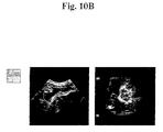
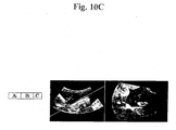
- the oblique sectional plane of the target object will be displayed by means of the above steps, as shown in Fig. 10.
- Fig. 10A and 10B shows the displays of sectional plane images in a vertical direction of the straight line and the curved line drawn on the A sectional plane image.
- the arbitrary straight line is automatically drawn on the reference sectional plane image beforehand. This is so that it is possible that the A sectional plane image perpendicular to the straight line is displayed.
- the straight line is indicated on the reference sectional plane image (e.g., the A sectional plane image)
- the lines on the image are rotated and the sectional plane image can be displayed in a vertical direction of the straight line.
- the target object can be scanned in real time by largely increasing the speed for performing the scan conversion of the 3D ultrasound data of the target object. Since the 3D information acquired by using the ultrasound is stored, even if the target object does not exist, the virtual scan is possible by using the stored data. Therefore, it is substantially helpful to a clinic and to a doctor treating his/her patient.
- the various multiple sectional plane images can be displayed differently from the prior art displaying the only reference sectional plane image of the target object and the user can select and display the desired slice image. Accordingly, it is very helpful in diagnosing the target object by using the ultrasound such as the ultrasound diagnostic device.
Abstract
Description
In accordance with an aspect of the present invention, there is provided an apparatus displaying a target object by using 3D ultrasound data, including: a scan conversion unit for performing scan conversion to convert conical coordinates of 3D data to Cartesian coordinates for display on a screen of a display device; and a rendering unit for rendering multiple sectional plane images, which are based on the scan-converted 3D data, parallel with a reference sectional plane.
In accordance with another aspect of the present invention, there is provided a method for displaying a target object by using 3D ultrasound data, including the steps of: storing indices matched with Cartesian coordinate of a screen in a display device to display a 3D image of the target object and operation resulting values of operations to convert Cartesian coordinates to conical coordinates coordinate in a geometric look-up table storage unit; receiving reference sectional plane information from an interface device, receiving 3D data of the target object from a probe or a 3D data storage device, and determining whether a current display region displaying an ultrasound image based on the 3D data of the target object is different from a previous display region on the screen; calculating the display region to display the image on the screen when the display region is changed; scan-converting 3D data of the target object by retrieving the operation resulting values from the geometric look-up table storage unit in order to convert Cartesian coordinates to conical coordinates corresponding to the calculated display region; and rendering multiple sectional plane images based on the scan-converted 3D data, wherein the multiple sectional plane images are parallel with a reference sectional plane in a vertical direction to the reference sectional plane.
In accordance with further another aspect of the present invention, there is provided a method for displaying slice images of a target object by using 3D ultrasound data, including the steps of: setting a reference sectional plane of the target object to be displayed; acquiring the 3D ultrasound data of the target object; displaying the reference sectional plane image; drawing a line on the displayed reference sectional plane for displaying a desired oblique sectional plane; and displaying the desired oblique sectional plane perpendicular to the reference sectional plane taken along the line by using an anti-aliasing method.
| m1 = [y4, y3, y2, y1] | Input y to m1 |
| m5 = m1 x [y4, y3, y2, y1] | m5 is a square of y |
| m2 = [z4, z3, z2, z1 ] | Input z to m2 |
| m6 = m2 x [z4, z3, z2, z1] | m6 is a square of z |
| m7 = m5 + m6 | m7 is equal to y2 + z2 |
| m3 = sqrt(m7) | m3 is a square root of y2 + z2 |
| m8 = m3 - a | m8 is [R4, R3, R2, R1] |
| m0 = [x4, x3, x2, x1] | Input x to m0 |
| m4 = m0 x [x4, x3, x2, x1] | m4 is a square of x |
| m5 = [R4, R3, R2, R1] | Input R to m5 |
| m5 = m5 x [R4, R3, R2, R1] | m5 is a square of R |
| m9 = m4 + m5 | m9 is equal to x2 + R2 |
| m10 = sqrt(m9) | m10 is a square root of x2 + R2 |
| m11 =m10-b | m11 is [r4, r3, r2, r1] |
Claims (16)
- An apparatus for displaying a target object by using 3-dimensional (3D) ultrasound data, comprising:a scan conversion unit for performing scan conversion to convert Cartesian coordinates for display on a screen of a display device to conical coordinates of 3D data; anda rendering unit for rendering multiple sectional plane images, based on the scan-converted 3D data, parallel with a reference sectional plane
- The apparatus as recited in claim 1, further comprising:wherein the scan conversion is carried out by retrieving the indices and the operation resulting values.a determination unit for receiving information of the reference sectional plane from an interface device, receiving the conical coordinates of the 3D data from a probe or a 3D data storage device, and determining whether a current display region displaying an image based on the 3D data of the target object is changed from a display region displaying a previous image on the screen;a display region calculation unit for calculating the display region to display the image on the screen when the display region is changed; anda geometric look-up table storage unit for storing indices of 3D data matched with Cartesian coordinates of the screen and resulting values of operations to convert the Cartesian coordinates to the conical coordinates,
- The apparatus as recited in claim 2, wherein a line is arbitrarily drawn on the reference sectional plane in order to display a desired sectional plane perpendicular to the reference sectional plane taken along the line, and wherein the rendering unit renders an image of the desired sectional plane through an anti-aliasing method.
- The apparatus as recited in claim 3, wherein the anti-aliasing method is carried out by retrieving an aliased portion in the desired section plane
- The apparatus as recited in claim 2, wherein the multiple sectional plane images are displayed in real time in an ultrasound diagnostic device.
- The apparatus as recited in claim 2, wherein a desired display layout for displaying the multiple sectional plane images is selected through the interface device, and wherein the rendering unit renders the multiple sectional plane images based on the scan-converted 3D data to be fitted in the selected display layout.
- A method for displaying a target object by using 3D ultrasound data, comprising the steps of:wherein the multiple sectional plane images are parallel with a reference sectional plane in a vertical direction to the reference sectional planestoring indices of 3D data matched with Cartesian coordinates of a screen in a display device to display a 3D image of the target object and resulting values of operations to convert Cartesian coordinates to conical coordinates in a geometric look-up table storage unit;receiving information of a reference sectional plane from an interface device, receiving 3D data of the target object from a probe or a 3D data storage device, and determining whether a current display region displaying an ultrasound image based on the 3D data of the target object is different from a previous display region on the screen;calculating the display region to display the image on the screen when the display region is changed;scan-converting 3D data of the target object by retrieving the resulting values from the geometric look-up table storage unit in order to convert the Cartesian coordinates corresponding to the calculated display region to the conical coordinates of the 3D data of the target object ; andrendering multiple sectional plane images based on the scan-converted 3D data,
- The method as recited in claim 7, further comprising the steps of:drawing a line on the reference sectional plane for displaying a desired sectional plan; anddisplaying the desired sectional plane perpendicular to the reference sectional plane taken along the line by using an anti-aliasing method.
- The method as recited in claim 7, further comprising the step of moving or editing an image displayed on the screen.
- The method as recited in claim 7, wherein the multiple sectional plane images are displayed in real time in an ultrasound diagnostic device.
- The method as recited in claim 7, wherein a desired display layout for displaying the multiple sectional plane images is selected through the interface device, and wherein the rendering step is performed by rendering the multiple sectional plane images based on the scan-converted 3D data to be fitted in the selected display layout.
- The method as recited in claim 8, wherein the anti-aliasing method is a selective anti-aliasing method for retrieving an aliased portion and performing the anti-aliasing method only for the aliased portion.
- A method for displaying slice images of a target object by using 3D ultrasound data, comprising the steps of:setting a reference sectional plane of the target object to be displayed;acquiring the 3D ultrasound data of the target object;displaying the reference sectional plane image;drawing a line on the displayed reference sectional plane for displaying a desired sectional plan; anddisplaying the desired sectional plane perpendicular to the reference sectional plane taken along the line by using an anti-aliasing method.
- The method as recited in claim 13, wherein the anti-aliasing method is a selective anti-alias method retrieving an aliased portion and performing the anti-aliasing method only for the aliased portion.
- The method as recited in claim 14, wherein the selective anti-aliasing method determines whether the 3D data are aliased or not by using a slop of the drawn line.
- The method as recited in claim 12, wherein the 3D ultrasound data are stored in a storage medium beforehand.
Priority Applications (1)
| Application Number | Priority Date | Filing Date | Title |
|---|---|---|---|
| EP10153704A EP2180340B1 (en) | 2003-12-31 | 2004-12-22 | Apparatus and method for displaying sectional planes of target object utilizing 3-dimensional ultrasound data |
Applications Claiming Priority (4)
| Application Number | Priority Date | Filing Date | Title |
|---|---|---|---|
| KR2003101188 | 2003-12-31 | ||
| KR20030101188 | 2003-12-31 | ||
| KR2004091704 | 2004-11-11 | ||
| KR1020040091704A KR100751852B1 (en) | 2003-12-31 | 2004-11-11 | Apparatus and method for displaying slices of a target object utilizing 3 dimensional ultrasound data thereof |
Related Child Applications (1)
| Application Number | Title | Priority Date | Filing Date |
|---|---|---|---|
| EP10153704.1 Division-Into | 2010-02-16 |
Publications (3)
| Publication Number | Publication Date |
|---|---|
| EP1550883A2 true EP1550883A2 (en) | 2005-07-06 |
| EP1550883A3 EP1550883A3 (en) | 2005-09-28 |
| EP1550883B1 EP1550883B1 (en) | 2010-03-24 |
Family
ID=34576058
Family Applications (2)
| Application Number | Title | Priority Date | Filing Date |
|---|---|---|---|
| EP04030404A Expired - Fee Related EP1550883B1 (en) | 2003-12-31 | 2004-12-22 | Apparatus and method for displaying sectional planes of target object utilizing 3-dimensional ultrasound data |
| EP10153704A Expired - Fee Related EP2180340B1 (en) | 2003-12-31 | 2004-12-22 | Apparatus and method for displaying sectional planes of target object utilizing 3-dimensional ultrasound data |
Family Applications After (1)
| Application Number | Title | Priority Date | Filing Date |
|---|---|---|---|
| EP10153704A Expired - Fee Related EP2180340B1 (en) | 2003-12-31 | 2004-12-22 | Apparatus and method for displaying sectional planes of target object utilizing 3-dimensional ultrasound data |
Country Status (6)
| Country | Link |
|---|---|
| US (1) | US7803112B2 (en) |
| EP (2) | EP1550883B1 (en) |
| JP (1) | JP4659446B2 (en) |
| KR (1) | KR100751852B1 (en) |
| CN (1) | CN100459940C (en) |
| DE (2) | DE602004026150D1 (en) |
Cited By (3)
| Publication number | Priority date | Publication date | Assignee | Title |
|---|---|---|---|---|
| EP2335596A1 (en) * | 2009-12-15 | 2011-06-22 | Medison Co., Ltd. | Ultrasound system and method of selecting slice image from three-dimensional ultrasound image |
| EP2455754A3 (en) * | 2010-11-18 | 2013-04-24 | Samsung Medison Co., Ltd. | Ultrasound System and Method for Providing Enlarged Image |
| EP2700364A2 (en) * | 2012-08-20 | 2014-02-26 | Samsung Medison Co., Ltd. | Method and apparatus for managing and displaying ultrasound image |
Families Citing this family (37)
| Publication number | Priority date | Publication date | Assignee | Title |
|---|---|---|---|---|
| CN100446007C (en) * | 2005-08-18 | 2008-12-24 | 鸿富锦精密工业(深圳)有限公司 | Method for implementing stagewise cutaway view |
| KR101126917B1 (en) * | 2005-10-13 | 2012-03-22 | 삼성메디슨 주식회사 | Image processing system and method for forming oblique slice images using 3 dimension images |
| KR100880125B1 (en) * | 2005-10-17 | 2009-01-23 | 주식회사 메디슨 | Image processing system and method for forming 3-dimension images using multiple sectional plane images |
| US20070249935A1 (en) * | 2006-04-20 | 2007-10-25 | General Electric Company | System and method for automatically obtaining ultrasound image planes based on patient specific information |
| US9612142B2 (en) | 2006-04-27 | 2017-04-04 | General Electric Company | Method and system for measuring flow through a heart valve |
| US20070255139A1 (en) * | 2006-04-27 | 2007-11-01 | General Electric Company | User interface for automatic multi-plane imaging ultrasound system |
| KR100947826B1 (en) * | 2006-05-24 | 2010-03-18 | 주식회사 메디슨 | Apparatus and method for displaying an ultrasound image |
| KR100923431B1 (en) * | 2006-06-26 | 2009-10-27 | 주식회사 메디슨 | Apparatus and method for displaying an ultrasound image |
| US8286079B2 (en) * | 2006-09-19 | 2012-10-09 | Siemens Medical Solutions Usa, Inc. | Context aware user interface for medical diagnostic imaging, such as ultrasound imaging |
| CN101290684B (en) * | 2007-04-19 | 2012-07-18 | 深圳迈瑞生物医疗电子股份有限公司 | Three-dimensional ultrasound pattern rapid plotting method and apparatus |
| JP5231840B2 (en) * | 2007-04-23 | 2013-07-10 | 株式会社東芝 | Ultrasonic diagnostic apparatus and control program |
| CN101292883B (en) * | 2007-04-23 | 2012-07-04 | 深圳迈瑞生物医疗电子股份有限公司 | Ultrasonic three-dimensional quick imaging method and apparatus |
| KR101009782B1 (en) * | 2008-10-28 | 2011-01-19 | (주)메디슨 | Ultrasound system and method providing wide image mode |
| EP2193747B8 (en) * | 2008-12-02 | 2015-06-17 | Samsung Medison Co., Ltd. | Ultrasound system and method of providing orientation help view |
| KR101120726B1 (en) * | 2009-08-27 | 2012-04-12 | 삼성메디슨 주식회사 | Ultrasound system and method of providing a plurality of slice plane images |
| KR101194282B1 (en) * | 2010-05-17 | 2012-10-24 | 삼성메디슨 주식회사 | Display system and display method of ultrasound apparatus |
| KR101194285B1 (en) * | 2010-08-24 | 2012-10-24 | 삼성메디슨 주식회사 | 3d ultrasound system for provide beam direction and method for operating 3d ultrasound system |
| JP5688197B2 (en) | 2010-08-31 | 2015-03-25 | ビー−ケー メディカル エーピーエス | 3D display of 2D ultrasound images |
| CN102397082B (en) * | 2010-09-17 | 2013-05-08 | 深圳迈瑞生物医疗电子股份有限公司 | Method and device for generating direction indicating diagram and ultrasonic three-dimensional imaging method and system |
| KR101286401B1 (en) * | 2010-11-11 | 2013-07-15 | 삼성메디슨 주식회사 | Ultrasound system and method for providing preview image |
| US8922554B2 (en) | 2011-03-18 | 2014-12-30 | Siemens Medical Solutions Usa, Inc. | Three-dimensional reconstruction for irregular ultrasound sampling grids |
| US8834376B2 (en) | 2012-02-28 | 2014-09-16 | Her Majesty The Queen In Right Of Canada As Represented By The Minister Of Health | Dispersive ultrasound technology as a diagnostic device for traumatic brain injuries |
| US9498188B2 (en) * | 2012-07-20 | 2016-11-22 | Fujifilm Sonosite, Inc. | Enhanced ultrasound imaging apparatus and associated methods of work flow |
| KR101538658B1 (en) | 2012-11-20 | 2015-07-22 | 삼성메디슨 주식회사 | Medical image display method and apparatus |
| WO2015076508A1 (en) | 2013-11-21 | 2015-05-28 | Samsung Medison Co., Ltd. | Method and apparatus for displaying ultrasound image |
| KR102315351B1 (en) * | 2014-10-07 | 2021-10-20 | 삼성메디슨 주식회사 | Imaging apparatus and controlling method of the same |
| KR102388130B1 (en) * | 2015-01-12 | 2022-04-19 | 삼성메디슨 주식회사 | Apparatus and method for displaying medical image |
| KR102551252B1 (en) * | 2015-11-11 | 2023-07-05 | 삼성메디슨 주식회사 | Ultrasonic diagnostic apparatus and operating method for the same |
| KR101701772B1 (en) * | 2016-08-18 | 2017-02-03 | (주) 성산연구소 | Method and apparatus for overlaying 2d drawing at ultrasonic waves image |
| CN106600695B (en) * | 2016-12-29 | 2020-04-10 | 深圳开立生物医疗科技股份有限公司 | Three-dimensional body reconstruction method and system |
| TWI639414B (en) * | 2017-11-17 | 2018-11-01 | 財團法人國家同步輻射研究中心 | Projection matching method for x-ray tomography |
| KR101900776B1 (en) * | 2017-12-14 | 2018-09-20 | 한국과학기술정보연구원 | Method and apparatus for visualizing of multi-slice |
| CN108294780A (en) * | 2018-01-31 | 2018-07-20 | 深圳开立生物医疗科技股份有限公司 | ultrasonic three-dimensional imaging method, ultrasonic three-dimensional imaging system and device |
| TWI648035B (en) * | 2018-03-22 | 2019-01-21 | 亞洲大學 | Minimal cut algorithm for spine segmentation |
| CN111047676B (en) * | 2018-10-12 | 2023-04-25 | 中国移动通信集团广西有限公司 | Image rendering method, device and storage medium |
| CN111110272B (en) * | 2019-12-31 | 2022-12-23 | 深圳开立生物医疗科技股份有限公司 | Ultrasonic image measurement information display method, device and equipment and readable storage medium |
| CN111583381B (en) * | 2020-05-06 | 2024-03-01 | 网易(杭州)网络有限公司 | Game resource map rendering method and device and electronic equipment |
Citations (3)
| Publication number | Priority date | Publication date | Assignee | Title |
|---|---|---|---|---|
| US5396890A (en) * | 1993-09-30 | 1995-03-14 | Siemens Medical Systems, Inc. | Three-dimensional scan converter for ultrasound imaging |
| US6374674B1 (en) * | 1998-10-14 | 2002-04-23 | Kabushiki Kaisha Toshiba | Ultrasonic diagnostic apparatus |
| US20040138560A1 (en) * | 2002-12-02 | 2004-07-15 | Gianluca Paladini | Real-time scan conversion and rendering of ultrasound data |
Family Cites Families (12)
| Publication number | Priority date | Publication date | Assignee | Title |
|---|---|---|---|---|
| NO943214D0 (en) * | 1994-08-30 | 1994-08-30 | Vingmed Sound As | Method of ultrasound imaging |
| JP3361692B2 (en) | 1996-05-10 | 2003-01-07 | ジーイー横河メディカルシステム株式会社 | Ultrasound diagnostic equipment |
| JP3862793B2 (en) * | 1996-11-19 | 2006-12-27 | 株式会社日立メディコ | Ultrasonic probe and ultrasonic diagnostic apparatus using the same |
| US6139498A (en) * | 1998-12-29 | 2000-10-31 | Ge Diasonics Israel, Ltd. | Ultrasound system performing simultaneous parallel computer instructions |
| US6102861A (en) | 1999-04-23 | 2000-08-15 | General Electric Company | Method and apparatus for three-dimensional ultrasound imaging using surface-enhanced volume rendering |
| US6607488B1 (en) * | 2000-03-02 | 2003-08-19 | Acuson Corporation | Medical diagnostic ultrasound system and method for scanning plane orientation |
| US6798907B1 (en) * | 2001-01-24 | 2004-09-28 | Advanced Digital Systems, Inc. | System, computer software product and method for transmitting and processing handwritten data |
| JP2003325513A (en) * | 2002-05-16 | 2003-11-18 | Aloka Co Ltd | Ultrasonic diagnostic apparatus |
| US6676605B2 (en) * | 2002-06-07 | 2004-01-13 | Diagnostic Ultrasound | Bladder wall thickness measurement system and methods |
| US7620220B2 (en) * | 2003-03-21 | 2009-11-17 | Boston Scientific Scimed, Inc. | Scan conversion of medical imaging data from polar format to cartesian format |
| US7436402B2 (en) * | 2004-09-01 | 2008-10-14 | Medison Co., Ltd. | Rendering apparatus and method for a real-time 3D ultrasound diagnostic system |
| KR100697728B1 (en) * | 2004-10-22 | 2007-03-21 | 주식회사 메디슨 | Apparatus and method for improving quality of an ultrasound sectional plane image |
-
2004
- 2004-11-11 KR KR1020040091704A patent/KR100751852B1/en active IP Right Grant
- 2004-12-08 US US11/006,609 patent/US7803112B2/en not_active Expired - Fee Related
- 2004-12-16 JP JP2004365067A patent/JP4659446B2/en not_active Expired - Fee Related
- 2004-12-22 EP EP04030404A patent/EP1550883B1/en not_active Expired - Fee Related
- 2004-12-22 EP EP10153704A patent/EP2180340B1/en not_active Expired - Fee Related
- 2004-12-22 DE DE602004026150T patent/DE602004026150D1/en active Active
- 2004-12-22 DE DE602004031392T patent/DE602004031392D1/en active Active
- 2004-12-31 CN CNB2004101044770A patent/CN100459940C/en not_active Expired - Fee Related
Patent Citations (3)
| Publication number | Priority date | Publication date | Assignee | Title |
|---|---|---|---|---|
| US5396890A (en) * | 1993-09-30 | 1995-03-14 | Siemens Medical Systems, Inc. | Three-dimensional scan converter for ultrasound imaging |
| US6374674B1 (en) * | 1998-10-14 | 2002-04-23 | Kabushiki Kaisha Toshiba | Ultrasonic diagnostic apparatus |
| US20040138560A1 (en) * | 2002-12-02 | 2004-07-15 | Gianluca Paladini | Real-time scan conversion and rendering of ultrasound data |
Non-Patent Citations (4)
| Title |
|---|
| KREEGER K A ET AL: "Mixing translucent polygons with volumes" VISUALIZATION '99. PROCEEDINGS SAN FRANCISCO, CA, USA 24-29 OCT. 1999, PISCATAWAY, NJ, USA,IEEE, US, 24 October 1999 (1999-10-24), pages 191-525, XP010364952 ISBN: 0-7803-5897-X * |
| NIKOLOV S I ET AL: "Real time 3D visualization of ultrasonic data using a standard PC" ULTRASONICS, IPC SCIENCE AND TECHNOLOGY PRESS LTD. GUILDFORD, GB, vol. 41, no. 6, August 2003 (2003-08), pages 421-426, XP004437390 ISSN: 0041-624X * |
| ROBB R A: "THREE-DIMENSIONAL VISUALIZATION IN MEDICINE AND BIOLOGY" HANDBOOK OF MEDICAL IMAGING, 1 September 2000 (2000-09-01), pages 685-712, XP002270429 * |
| SAKAS G ET AL: "Interactive visualization of large scalar voxel fields" PROCEEDINGS OF THE VISUALIZATION CONFERENCE. BOSTON, OCT. 19 - 23, 1992, LOS ALAMITOS, IEEE COMP. SOC. PRESS, US, vol. CONF. 3, 19 October 1992 (1992-10-19), pages 29-36, XP010029602 ISBN: 0-8186-2897-9 * |
Cited By (5)
| Publication number | Priority date | Publication date | Assignee | Title |
|---|---|---|---|---|
| EP2335596A1 (en) * | 2009-12-15 | 2011-06-22 | Medison Co., Ltd. | Ultrasound system and method of selecting slice image from three-dimensional ultrasound image |
| EP2455754A3 (en) * | 2010-11-18 | 2013-04-24 | Samsung Medison Co., Ltd. | Ultrasound System and Method for Providing Enlarged Image |
| EP2700364A2 (en) * | 2012-08-20 | 2014-02-26 | Samsung Medison Co., Ltd. | Method and apparatus for managing and displaying ultrasound image |
| EP2700364A3 (en) * | 2012-08-20 | 2014-07-02 | Samsung Medison Co., Ltd. | Method and apparatus for managing and displaying ultrasound image |
| US9332965B2 (en) | 2012-08-20 | 2016-05-10 | Samsung Medison Co., Ltd. | Method and apparatus for managing and displaying ultrasound image according to an observation operation |
Also Published As
| Publication number | Publication date |
|---|---|
| EP1550883A3 (en) | 2005-09-28 |
| DE602004031392D1 (en) | 2011-03-24 |
| DE602004026150D1 (en) | 2010-05-06 |
| JP4659446B2 (en) | 2011-03-30 |
| EP2180340A1 (en) | 2010-04-28 |
| CN1636521A (en) | 2005-07-13 |
| US20050187474A1 (en) | 2005-08-25 |
| CN100459940C (en) | 2009-02-11 |
| US7803112B2 (en) | 2010-09-28 |
| JP2005193021A (en) | 2005-07-21 |
| EP2180340B1 (en) | 2011-02-09 |
| KR100751852B1 (en) | 2007-08-27 |
| KR20050069878A (en) | 2005-07-05 |
| EP1550883B1 (en) | 2010-03-24 |
Similar Documents
| Publication | Publication Date | Title |
|---|---|---|
| EP1550883B1 (en) | Apparatus and method for displaying sectional planes of target object utilizing 3-dimensional ultrasound data | |
| EP3003161B1 (en) | Method for 3d acquisition of ultrasound images | |
| US6461298B1 (en) | Three-dimensional imaging system | |
| JP4864354B2 (en) | Ultrasound system | |
| US6515657B1 (en) | Ultrasonic imager | |
| JP5265850B2 (en) | User interactive method for indicating a region of interest | |
| JP4742304B2 (en) | Ultrasound cross-sectional image improvement apparatus and method | |
| EP1600891A1 (en) | Ultrasonic diagnostic apparatus and image processing method | |
| US20080072151A1 (en) | Context aware user interface for medical diagnostic imaging, such as ultrasound imaging | |
| JP2007296330A (en) | User interface for automatic multi-plane imaging ultrasound system | |
| US20060250395A1 (en) | Apparatus and method for rendering volume data | |
| JP2007275588A (en) | Cross reference measurement for diagnostic medical imaging | |
| WO2006022815A1 (en) | View assistance in three-dimensional ultrasound imaging | |
| JP2010530777A (en) | System and method for labeling a three-dimensional volume image on a two-dimensional display of an ultrasound imaging system | |
| JP2001167251A (en) | Medical image processor | |
| US20070255138A1 (en) | Method and apparatus for 3D visualization of flow jets | |
| JP3352613B2 (en) | Ultrasound image diagnostic equipment | |
| US6429862B1 (en) | Three-dimensional image processing apparatus | |
| JP2000296129A (en) | Ultrasonograph | |
| JPH06215153A (en) | Image processor | |
| EP4238534A1 (en) | Method for determining object area from three-dimensional model, and three-dimensional model processing device | |
| US7436402B2 (en) | Rendering apparatus and method for a real-time 3D ultrasound diagnostic system | |
| JP2002306481A (en) | Ultrasonic image processor | |
| JP4575089B2 (en) | Rendering apparatus and method for real-time three-dimensional ultrasonic diagnostic system | |
| EP1632789A1 (en) | Rendering apparatus and method for a real-time 3D ultrasound diagnostic system |
Legal Events
| Date | Code | Title | Description |
|---|---|---|---|
| PUAI | Public reference made under article 153(3) epc to a published international application that has entered the european phase |
Free format text: ORIGINAL CODE: 0009012 |
|
| AK | Designated contracting states |
Kind code of ref document: A2 Designated state(s): AT BE BG CH CY CZ DE DK EE ES FI FR GB GR HU IE IS IT LI LT LU MC NL PL PT RO SE SI SK TR |
|
| AX | Request for extension of the european patent |
Extension state: AL BA HR LV MK YU |
|
| PUAL | Search report despatched |
Free format text: ORIGINAL CODE: 0009013 |
|
| AK | Designated contracting states |
Kind code of ref document: A3 Designated state(s): AT BE BG CH CY CZ DE DK EE ES FI FR GB GR HU IE IS IT LI LT LU MC NL PL PT RO SE SI SK TR |
|
| AX | Request for extension of the european patent |
Extension state: AL BA HR LV MK YU |
|
| RIC1 | Information provided on ipc code assigned before grant |
Ipc: 7G 01S 7/52 B Ipc: 7G 06T 17/40 B Ipc: 7G 01S 15/89 A |
|
| 17P | Request for examination filed |
Effective date: 20051108 |
|
| AKX | Designation fees paid |
Designated state(s): DE FR IT |
|
| 17Q | First examination report despatched |
Effective date: 20070122 |
|
| GRAP | Despatch of communication of intention to grant a patent |
Free format text: ORIGINAL CODE: EPIDOSNIGR1 |
|
| GRAS | Grant fee paid |
Free format text: ORIGINAL CODE: EPIDOSNIGR3 |
|
| GRAA | (expected) grant |
Free format text: ORIGINAL CODE: 0009210 |
|
| AK | Designated contracting states |
Kind code of ref document: B1 Designated state(s): DE FR IT |
|
| REF | Corresponds to: |
Ref document number: 602004026150 Country of ref document: DE Date of ref document: 20100506 Kind code of ref document: P |
|
| PLBE | No opposition filed within time limit |
Free format text: ORIGINAL CODE: 0009261 |
|
| STAA | Information on the status of an ep patent application or granted ep patent |
Free format text: STATUS: NO OPPOSITION FILED WITHIN TIME LIMIT |
|
| 26N | No opposition filed |
Effective date: 20101228 |
|
| PG25 | Lapsed in a contracting state [announced via postgrant information from national office to epo] |
Ref country code: IT Free format text: LAPSE BECAUSE OF FAILURE TO SUBMIT A TRANSLATION OF THE DESCRIPTION OR TO PAY THE FEE WITHIN THE PRESCRIBED TIME-LIMIT Effective date: 20100324 |
|
| REG | Reference to a national code |
Ref country code: FR Ref legal event code: PLFP Year of fee payment: 12 |
|
| REG | Reference to a national code |
Ref country code: FR Ref legal event code: PLFP Year of fee payment: 13 |
|
| REG | Reference to a national code |
Ref country code: FR Ref legal event code: PLFP Year of fee payment: 14 |
|
| REG | Reference to a national code |
Ref country code: FR Ref legal event code: PLFP Year of fee payment: 15 |
|
| PGFP | Annual fee paid to national office [announced via postgrant information from national office to epo] |
Ref country code: DE Payment date: 20191105 Year of fee payment: 16 |
|
| PGFP | Annual fee paid to national office [announced via postgrant information from national office to epo] |
Ref country code: IT Payment date: 20191216 Year of fee payment: 16 Ref country code: FR Payment date: 20191107 Year of fee payment: 16 |
|
| REG | Reference to a national code |
Ref country code: DE Ref legal event code: R119 Ref document number: 602004026150 Country of ref document: DE |
|
| PG25 | Lapsed in a contracting state [announced via postgrant information from national office to epo] |
Ref country code: IT Free format text: LAPSE BECAUSE OF NON-PAYMENT OF DUE FEES Effective date: 20201222 Ref country code: FR Free format text: LAPSE BECAUSE OF NON-PAYMENT OF DUE FEES Effective date: 20201231 |
|
| PG25 | Lapsed in a contracting state [announced via postgrant information from national office to epo] |
Ref country code: DE Free format text: LAPSE BECAUSE OF NON-PAYMENT OF DUE FEES Effective date: 20210701 |