EP1555039A2 - Respiratory mask with forehead support - Google Patents
Respiratory mask with forehead support Download PDFInfo
- Publication number
- EP1555039A2 EP1555039A2 EP04024718A EP04024718A EP1555039A2 EP 1555039 A2 EP1555039 A2 EP 1555039A2 EP 04024718 A EP04024718 A EP 04024718A EP 04024718 A EP04024718 A EP 04024718A EP 1555039 A2 EP1555039 A2 EP 1555039A2
- Authority
- EP
- European Patent Office
- Prior art keywords
- connecting element
- guide
- respiratory mask
- mask according
- relative
- Prior art date
- Legal status (The legal status is an assumption and is not a legal conclusion. Google has not performed a legal analysis and makes no representation as to the accuracy of the status listed.)
- Granted
Links
- 210000001061 forehead Anatomy 0.000 title claims description 25
- 230000000241 respiratory effect Effects 0.000 title claims description 17
- 230000029058 respiratory gaseous exchange Effects 0.000 claims abstract description 21
- 230000008878 coupling Effects 0.000 claims description 7
- 238000010168 coupling process Methods 0.000 claims description 7
- 238000005859 coupling reaction Methods 0.000 claims description 7
- 238000007789 sealing Methods 0.000 claims description 4
- 238000006073 displacement reaction Methods 0.000 description 2
- 230000010354 integration Effects 0.000 description 2
- 230000006978 adaptation Effects 0.000 description 1
- 238000005452 bending Methods 0.000 description 1
- 230000005540 biological transmission Effects 0.000 description 1
- 238000010276 construction Methods 0.000 description 1
- 210000000887 face Anatomy 0.000 description 1
- 210000003128 head Anatomy 0.000 description 1
- 238000001746 injection moulding Methods 0.000 description 1
- 238000004519 manufacturing process Methods 0.000 description 1
- 230000008719 thickening Effects 0.000 description 1
- 238000009423 ventilation Methods 0.000 description 1
Images


Classifications
-
- A—HUMAN NECESSITIES
- A61—MEDICAL OR VETERINARY SCIENCE; HYGIENE
- A61M—DEVICES FOR INTRODUCING MEDIA INTO, OR ONTO, THE BODY; DEVICES FOR TRANSDUCING BODY MEDIA OR FOR TAKING MEDIA FROM THE BODY; DEVICES FOR PRODUCING OR ENDING SLEEP OR STUPOR
- A61M16/00—Devices for influencing the respiratory system of patients by gas treatment, e.g. mouth-to-mouth respiration; Tracheal tubes
- A61M16/06—Respiratory or anaesthetic masks
- A61M16/0605—Means for improving the adaptation of the mask to the patient
- A61M16/0616—Means for improving the adaptation of the mask to the patient with face sealing means comprising a flap or membrane projecting inwards, such that sealing increases with increasing inhalation gas pressure
-
- A—HUMAN NECESSITIES
- A61—MEDICAL OR VETERINARY SCIENCE; HYGIENE
- A61M—DEVICES FOR INTRODUCING MEDIA INTO, OR ONTO, THE BODY; DEVICES FOR TRANSDUCING BODY MEDIA OR FOR TAKING MEDIA FROM THE BODY; DEVICES FOR PRODUCING OR ENDING SLEEP OR STUPOR
- A61M16/00—Devices for influencing the respiratory system of patients by gas treatment, e.g. mouth-to-mouth respiration; Tracheal tubes
- A61M16/06—Respiratory or anaesthetic masks
- A61M16/0605—Means for improving the adaptation of the mask to the patient
- A61M16/0633—Means for improving the adaptation of the mask to the patient with forehead support
- A61M16/0644—Means for improving the adaptation of the mask to the patient with forehead support having the means for adjusting its position
-
- A—HUMAN NECESSITIES
- A61—MEDICAL OR VETERINARY SCIENCE; HYGIENE
- A61M—DEVICES FOR INTRODUCING MEDIA INTO, OR ONTO, THE BODY; DEVICES FOR TRANSDUCING BODY MEDIA OR FOR TAKING MEDIA FROM THE BODY; DEVICES FOR PRODUCING OR ENDING SLEEP OR STUPOR
- A61M16/00—Devices for influencing the respiratory system of patients by gas treatment, e.g. mouth-to-mouth respiration; Tracheal tubes
- A61M16/0057—Pumps therefor
- A61M16/0066—Blowers or centrifugal pumps
-
- A—HUMAN NECESSITIES
- A61—MEDICAL OR VETERINARY SCIENCE; HYGIENE
- A61M—DEVICES FOR INTRODUCING MEDIA INTO, OR ONTO, THE BODY; DEVICES FOR TRANSDUCING BODY MEDIA OR FOR TAKING MEDIA FROM THE BODY; DEVICES FOR PRODUCING OR ENDING SLEEP OR STUPOR
- A61M16/00—Devices for influencing the respiratory system of patients by gas treatment, e.g. mouth-to-mouth respiration; Tracheal tubes
- A61M16/08—Bellows; Connecting tubes ; Water traps; Patient circuits
- A61M16/0816—Joints or connectors
- A61M16/0825—Joints or connectors with ball-sockets
Definitions
- the invention relates to a breathing mask comprising a mask body, a hose connection and at least one Has sealing element and provided with a forehead support that is positionable relative to the mask body is arranged.
- Such breathing masks can be used as nasal masks as well be designed as full-face masks.
- such respiratory masks have a movable forehead support, the optimal positioning of the mask on different shaped faces of each patient supported.
- the movement of the forehead support takes place relative to the mask body by pivoting a transverse axis or by pivoting about a vertical Axis.
- the object of the present invention is a respiratory mask the type mentioned in the introduction to construct such that an adjustment for the forehead support both a has high functionality as well as in a simple manner integrated the geometric design of the mask body can be.
- a the forehead support with the mask main body coupling connecting element flexible and relative to a Guide is arranged so displaceable that the connecting element Predictably far out of the leadership and relative to the leadership in at least two different ones Positioning is locked.
- the displaceable arrangement of the connecting element in the leadership such that, depending on the respective Arresting a different wide protruding from the Guidance is realized, allows direct adjustment the breathing mask on the patient's face.
- the connecting element is formed spirally.
- the connecting element as a link chain provided with a rigid tail is trained.
- a simple mechanical realization can be achieved be that a locking element for locking the Connecting element relative to the guide at least one Has projection and at least one recess.
- Connecting element has a control button.
- a structurally simple realization using Bending stresses within the connecting element can thereby take place that the connecting element relative to the guide can be locked by a resilient tension.
- a direct adjustment of the forehead support on the In particular, the patient's face is achieved by that one of the leadership outstanding end of the connecting element substantially perpendicular to a ground plane of the mask body runs.
- a fixation of the forehead support remote from the end of the Connecting element can be effected in that the connecting element in the area of his forehead support facing away End at least one adapted to a fixing pin FixierausEnglishung having.
- a fixation of the connecting element in at least two different fixation positions can be achieved be that the connecting element at least two Has FixierausEnglishlessness.
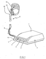
- Fig. 1 shows the basic structure of a device for ventilation.
- a device housing (1) with control panel (2) and display (3) is in a device interior arranged a breathing gas pump.
- a breathing gas pump is in a device interior arranged a breathing gas pump.
- a coupling (4) is a breathing gas hose (5) connected.
- the breathing gas hose (5) can be an additional pressure measuring hose (6) run, the via a pressure input port (7) with the Device housing (1) is connectable.
- the device housing (1) has an interface (8).
- an expiratory element 9 arranged in the region of the device housing (1) facing away from expansion the breathing gas hose (5) is an expiratory element (9) arranged.
- An exhalation valve can also be used become.
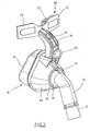
- Fig. 1 also shows a breathing mask (10), which as Nasal mask is formed.
- a fixation in the area of a Head of a patient can be done via a hood (11).
- the breathing mask (10) has a hose coupling (12).
- the hose coupling (12) for the not shown Breathing gas hose (5) is with a mask body (13) the breathing mask (10) connected via a joint (14), the ball joint is formed.
- the joint (14) consists of a the hose coupling (12) connected inner part (15) and an outer shell connected to the mask base body (13) (16).
- the inner part (15) is at least partially formed spherical segment-like and the outer shell (16) extends along at least a part of the spherical segment-like Surface of the inner part (15).
- a sealing element (17) arranged the at least partially formed as a lip seal is.
- a connecting element (18) is about a connecting element (18), the at least partially supported by a guide (19), is a forehead support (20) with the mask main body (13) coupled.
- the forehead rest (20) has a carrier (21) on, which holds a forehead pad (22).
- the connecting element (18) is within the leadership (19) in at least two different Positions can be locked. A catch as well a positioning of the connecting element (18) takes place using a control button (23). When pressing the Control button (23), the lock is released and the connecting element (18) can be moved within the guide (19) become. After releasing the control button (23) a renewed locking of the connecting element takes place (18).
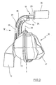
- the first band (24) is positionable within the guide (19), the second band (25) runs along one outer boundary of the guide (19).
- the band (25) points in Area of an end piece (26) on side bars (27) in Side grooves of the guide (19) intervene.
- About the tail (26), a displacement of the connecting element (18) take place.
- the band (24) serves essentially for support.
- Fig. 3 illustrates that during a displacement of the connecting element (18) relative to the guide (19) positioning the forehead support (20) substantially perpendicular to a ground plane (29) of the breathing mask (10). These Arrangement supports the direct position specification of Forehead support (20).
- FIG. 4 shows the structure of the breathing mask (10) according to FIG. 3 corresponding to viewing direction IV in Fig. 3. It can be seen in particular the substantially symmetrical structure relative to the in Fig. 4 perpendicular center plane.
- Fig. 5 illustrates a vertical section through the Respiratory mask (10) according to FIG. 4. It can be seen, for example, that the bands (24, 25) within the guide of a Transverse element (30) are supported relative to each other.
- the Cross element (30) is in two parts by projections (31, 32) formed, each starting from the bands (24, 25) extend in directions facing each other and have a matched shape, so that the Protrusions (31, 32) partially engage with each other.
- FIG. 6 shows an embodiment in which the guide (19) separately and for connection to a not shown Maskengrund stresses (13) is formed.
- the connecting element (18) is similar to band and with an internal stress realized a leaf spring.
- the connecting element (18) extends through a recess (33) of the guide (19) through.
- In the region of the recess (33) is a as Part of the guide (19) formed projection (34) arranged, the at a corresponding positioning of the connecting element (18) in a recess (35) of the connecting element (18) engages and thereby a lock the connecting element (18) relative to the guide (19) performs.
- a plurality of recesses (35) arranged one behind the other so that depending on the selection of the respective locking positioning the connecting element (18) different far out of the recess (25) protrudes and thereby different distances of the forehead support (20) realized relative to the mask body (13).
- the fixing pin (37) is in particular thought of the fixing pin (37) in one out the FixierausEnglishung outstanding area with an edge thickening to provide.
- the connecting element (18) provided with two Fixieraus strictlystead (36). hereby it is possible a respective Fixierposition réelle pretend.
- Vorgebbarkeit it is possible in Dependence on the length of the recess (33) in Direction of the forehead support (20) protruding end of the Connecting element (18) the fixation of the recess (33) applied end of the connecting element (18) in such a way to pretend that the curvature of the connecting element (18) between the recess (33) and the fixing recess (36) lies within a predefinable interval and in particular excessive deflection is avoided.
Abstract
Description
Die Erfindung betrifft eine Atemmaske, die einen Maskengrundkörper, einen Schlauchanschluß sowie mindestens ein Dichtelement aufweist und die mit einer Stirnstütze versehen ist, die relativ zum Maskengrundkörper positionierbar angeordnet ist.The invention relates to a breathing mask comprising a mask body, a hose connection and at least one Has sealing element and provided with a forehead support that is positionable relative to the mask body is arranged.
Derartige Atemmasken können sowohl als Nasalmasken als auch als Vollgesichtsmasken ausgebildet sein. Typischerweise verfügen derartige Atemmasken über eine bewegliche Stirnstütze, die eine optimale Positionierung der Maske auf unterschiedlich geformten Gesichtern der jeweiligen Patienten unterstützt. Üblicherweise erfolgt die Bewegung der Stirnstütze relativ zum Maskengrundkörper durch ein Schwenken um eine Querachse oder durch ein Schwenken um eine senkrechte Achse. Such breathing masks can be used as nasal masks as well be designed as full-face masks. typically, such respiratory masks have a movable forehead support, the optimal positioning of the mask on different shaped faces of each patient supported. Usually, the movement of the forehead support takes place relative to the mask body by pivoting a transverse axis or by pivoting about a vertical Axis.
Nachteilig sowohl beim Schwenken der Stirnstütze relativ zu einer Querachse als auch beim Schwenken um eine senkrechte Achse herum ist es, daß derartige Bewegungen nur indirekt den Abstand zwischen der Stirnstütze und dem Maskengrundkörper festlegen.A disadvantage both when pivoting the forehead support relative to a transverse axis and when pivoting about a vertical Axis around it is that such movements only indirectly the distance between the forehead support and the mask body establish.
Bekannt ist es darüber hinaus, eine Verstellung der Stirnstütze relativ zum Maskengrundkörper entsprechend der DE 101 55 152 unter Verwendung von Stangen vorzunehmen. Die Verwendung derartiger Stangen oder die Verwendung von Schrauben führt aber zu Integrationsproblemen bei der Einführung dieser Bauelemente in die Maskengeometrie.It is known, moreover, an adjustment of the forehead rest relative to the mask body according to DE 101 55 152 using rods. The Use of such rods or the use of But screw leads to integration problems during the introduction of these components in the mask geometry.
Aufgabe der vorliegenden Erfindung ist es, eine Atemmaske der einleitend genannten Art derart zu konstruieren, daß eine Verstelleinrichtung für die Stirnstütze sowohl eine hohe Funktionalität aufweist als auch in einfacher Weise in die geometrische Gestaltung des Maskengrundkörpers integriert werden kann.The object of the present invention is a respiratory mask the type mentioned in the introduction to construct such that an adjustment for the forehead support both a has high functionality as well as in a simple manner integrated the geometric design of the mask body can be.
Diese Aufgabe wird erfindungsgemäß dadurch gelöst, daß ein die Stirnstütze mit dem Maskengrundkörper koppelndes Verbindungselement flexibel ausgebildet und relativ zu einer Führung derart verschieblich angeordnet ist, daß das Verbindungselement vorgebbar weit aus der Führung herausragt und relativ zur Führung in mindestens zwei unterschiedlichen Positionierungen arretierbar ist.This object is achieved in that a the forehead support with the mask main body coupling connecting element flexible and relative to a Guide is arranged so displaceable that the connecting element Predictably far out of the leadership and relative to the leadership in at least two different ones Positioning is locked.
Die verschiebliche Anordnung des Verbindungselementes in der Führung derart, daß in Abhängigkeit von der jeweiligen Arretierung ein unterschiedlich weites Herausragen aus der Führung realisiert ist, ermöglicht eine direkte Verstellbarkeit der Atemmaske auf dem Gesicht des Patienten. Durch die flexible Ausbildung des verbindungselementes ist es möglich, eine Integration in die gerundete Kontur des Maskengrundkörpers vorzunehmen.The displaceable arrangement of the connecting element in the leadership such that, depending on the respective Arresting a different wide protruding from the Guidance is realized, allows direct adjustment the breathing mask on the patient's face. By it is the flexible design of the connecting element possible, an integration in the rounded contour of the mask body make.
Eine spritzgußtechnische Herstellung der verwendeten Bauteile wird dadurch unterstützt, daß das Verbindungselement bandartig ausgebildet ist.An injection molding production of the components used is supported by the fact that the connecting element is formed band-like.
Gemäß einer anderen Ausführungsform ist auch daran gedacht, daß das Verbindungselement spiralartig ausgebildet ist.According to another embodiment, it is also intended that the connecting element is formed spirally.
Darüber hinaus ist es auch möglich, daß das Verbindungselement als eine mit einem steifen Endstück versehene Gliederkette ausgebildet ist.In addition, it is also possible that the connecting element as a link chain provided with a rigid tail is trained.
Eine Anpassung an einen typischen Formverlauf einer Atemmaske erfolgt dadurch, daß die Führung eine gekrümmte Führungsbahn für das Verbindungselement aufweist.An adaptation to a typical shape of a breathing mask takes place in that the guide a curved guideway having for the connecting element.
Eine einfache mechanische Realisierung kann dadurch erreicht werden, daß ein Arretierelement zur Arretierung des Verbindungselementes relativ zur Führung mindestens einen Vorsprung und mindestens eine Ausnehmung aufweist.A simple mechanical realization can be achieved be that a locking element for locking the Connecting element relative to the guide at least one Has projection and at least one recess.
Eine gute Bedienbarkeit wird dadurch unterstützt, daß das Verbindungselement eine Bedientaste aufweist.Good usability is supported by the fact that the Connecting element has a control button.
Eine konstruktiv einfache Realisierung unter Nutzung von Biegespannungen innerhalb des Verbindungselementes kann dadurch erfolgen, daß das Verbindungselement relativ zur Führung durch eine federnde Verspannung arretierbar ist.A structurally simple realization using Bending stresses within the connecting element can thereby take place that the connecting element relative to the guide can be locked by a resilient tension.
Eine erhöhte mechanische Stabilität sowie eine verbesserte Führungsgenauigkeit können dadurch erreicht werden, daß das Verbindungselement zwei relativ zueinander im wesentlichen parallel verlaufende Bänder aufweist.An increased mechanical stability as well as an improved Guidance accuracy can be achieved by the Connecting element two relative to each other substantially having parallel bands.
Insbesondere ist daran gedacht, daß eines der Bänder zur Führung und das andere der Bänder zur Abstützung des Verbindungselementes ausgebildet ist.In particular, it is thought that one of the bands for Guide and the other of the bands for supporting the connecting element is trained.
Eine direkte Verstellmöglichkeit der Stirnstütze auf dem Gesicht des Patienten wird insbesondere dadurch erreicht, daß ein aus der Führung herausragendes Ende des Verbindungselementes im wesentlichen senkrecht zu einer Grundebene des Maskengrundkörpers verläuft.A direct adjustment of the forehead support on the In particular, the patient's face is achieved by that one of the leadership outstanding end of the connecting element substantially perpendicular to a ground plane of the mask body runs.
Eine Fixierung des der Stirnstütze abgewandten Endes des Verbindungselementes kann dadurch erfolgen, daß das Verbindungselement im Bereich seines der Stirnstütze abgewandten Endes mindestens eine an einen Fixierzapfen angepaßte Fixierausnehmung aufweist.A fixation of the forehead support remote from the end of the Connecting element can be effected in that the connecting element in the area of his forehead support facing away End at least one adapted to a fixing pin Fixierausnehmung having.
Eine Fixierung des Verbindungselementes in mindestens zwei unterschiedlichen Fixierungspositionen kann dadurch erreicht werden, daß das Verbindungselement mindestens zwei Fixierausnehmungen aufweist.A fixation of the connecting element in at least two different fixation positions can be achieved be that the connecting element at least two Has Fixierausnehmungen.
In den Zeichnungen sind Ausführungsbeispiele der Erfindung schematisch dargestellt. Es zeigen:
- Fig. 1
- Eine perspektivische Darstellung eines Beamtungsgerätes mit Verbindungsschlauch zu einer Beatmungsmaske,
- Fig. 2
- eine perspektivische Darstellung einer Atemmaske mit Stirnstütze, bei der ein Verbindungselement zwischen der Stirnstütze und einem Maskengrundkörper flexibel ausgebildet und in einer Schiene geführt ist,
- Fig. 3
- eine perspektivische Darstellung einer anderen Atemmaske, bei der das Verbindungselement zwischen der Stirnstütze und dem Maskengrundkörper aus zwei mit einem Abstand parallel zueinander geführten flexiblen Bändern ausgebildet ist,
- Fig. 4
- eine weitere Darstellung der Atemmaske gemäß Fig. 3,
- Fig. 5
- ein Querschnitt gemäß Schnittlinie V-V in Fig. 4,
- Fig. 6
- eine Ausführungsform, bei der das Verbindungselement blattfederartig ausgebildet und in einer Führung arretiert ist und
- Fig. 7
- eine gegenüber Fig. 6 abgewandelte Ausführungsform mit zweifacher verstellbarer Fixierung des Verbindungselementes.
- Fig. 1
- A perspective view of an official device with connecting tube to a respiratory mask,
- Fig. 2
- 3 is a perspective view of a breathing mask with forehead rest, in which a connecting element between the forehead rest and a mask main body is flexibly formed and guided in a rail,
- Fig. 3
- a perspective view of another breathing mask in which the connecting element between the forehead support and the mask main body is formed of two with a distance parallel to each other guided flexible bands,
- Fig. 4
- a further illustration of the breathing mask according to FIG. 3,
- Fig. 5
- a cross section along section line VV in Fig. 4,
- Fig. 6
- an embodiment in which the connecting element is formed like a leaf spring and locked in a guide and
- Fig. 7
- a comparison with FIG. 6 modified embodiment with double adjustable fixation of the connecting element.
Fig. 1 zeigt den grundsätzlichen Aufbau einer Vorrichtung zur Beatmung. Im Bereich eines Gerätegehäuses (1) mit Bedienfeld (2) sowie Anzeige (3) ist in einem Geräteinnenraum eine Atemgaspumpe angeordnet. Über eine Kopplung (4) wird ein Atemgasschlauch (5) angeschlossen. Entlang des Atemgasschlauches (5) kann ein zusätzlicher Druckmeßschlauch (6) verlaufen, der über einen Druckeingangsstutzen (7) mit dem Gerätegehäuse (1) verbindbar ist. Zur Ermöglichung einer Datenübertragung weist das Gerätegehäuse (1) eine Schnittstelle (8) auf. Fig. 1 shows the basic structure of a device for ventilation. In the area of a device housing (1) with control panel (2) and display (3) is in a device interior arranged a breathing gas pump. About a coupling (4) is a breathing gas hose (5) connected. Along the breathing gas hose (5) can be an additional pressure measuring hose (6) run, the via a pressure input port (7) with the Device housing (1) is connectable. To enable one Data transmission, the device housing (1) has an interface (8).
Im Bereich einer dem Gerätegehäuse (1) abgewandten Ausdehnung des Atemgasschlauches (5) ist ein Ausatmungselement (9) angeordnet. Ebenfalls kann ein Ausatemventil verwendet werden.In the region of the device housing (1) facing away from expansion the breathing gas hose (5) is an expiratory element (9) arranged. An exhalation valve can also be used become.
Fig. 1 zeigt darüber hinaus eine Atemmaske (10), die als Nasalmaske ausgebildet ist. Eine Fixierung im Bereich eines Kopfes eines Patienten kann über eine Kopfhaube (11) erfolgen. Im Bereich ihrer dem Atemgasschlauch (5) zugewandten Ausdehnung weist die Atemmaske (10) eine Schlauchkupplung (12) auf.Fig. 1 also shows a breathing mask (10), which as Nasal mask is formed. A fixation in the area of a Head of a patient can be done via a hood (11). In the area of their breathing gas hose (5) facing Expansion, the breathing mask (10) has a hose coupling (12).
Aus Fig. 2 ist der Aufbau der Atemmaske (10) im Detail zu erkennen. Die Schlauchkupplung (12) für den nicht dargestellten Atemgasschlauch (5) ist mit einem Maskengrundkörper (13) der Atemmaske (10) über ein Gelenk (14) verbunden, das kugelgelenkartig ausgebildet ist. Beim dargestellten Ausführungsbeispiel besteht das Gelenk (14) aus einem mit der Schlauchkupplung (12) verbundenen Innenteil (15) sowie einer mit dem Maskengrundkörper (13) verbundenen Außenschale (16). Das Innenteil (15) ist wenigstens bereichsweise kugelsegmentartig ausgebildet und die Außenschale (16) erstreckt sich entlang wenigstens eines Teiles der kugelsegmentartigen Oberfläche des Innenteiles (15).From Fig. 2, the structure of the breathing mask (10) in detail to detect. The hose coupling (12) for the not shown Breathing gas hose (5) is with a mask body (13) the breathing mask (10) connected via a joint (14), the ball joint is formed. When presented Embodiment, the joint (14) consists of a the hose coupling (12) connected inner part (15) and an outer shell connected to the mask base body (13) (16). The inner part (15) is at least partially formed spherical segment-like and the outer shell (16) extends along at least a part of the spherical segment-like Surface of the inner part (15).
Am Maskengrundkörper (13) ist zur Abdichtung relativ zu einem Gesicht eines Patienten ein Dichtelement (17) angeordnet, das mindestens bereichsweise als Lippendichtung ausgebildet ist. Über ein Verbindungselement (18), das mindestens bereichsweise von einer Führung (19) gehaltert ist, wird eine Stirnstütze (20) mit dem Maskengrundkörper (13) gekoppelt. Die Stirnstütze (20) weist einen Träger (21) auf, der ein Stirnpolster (22) haltert. At the mask main body (13) is for sealing relative to a Face of a patient a sealing element (17) arranged the at least partially formed as a lip seal is. About a connecting element (18), the at least partially supported by a guide (19), is a forehead support (20) with the mask main body (13) coupled. The forehead rest (20) has a carrier (21) on, which holds a forehead pad (22).
Bei dem in Fig. 2 dargestellten Ausführungsbeispiel ist die Führung (19) ausgehend vom Maskengrundkörper (13) in eine von der Schlauchkupplung (12) wegweisende Richtung gekrümmt ausgebildet. wenigstens bereichsweise innerhalb der Führung (19) verläuft das Verbindungselement (18), das flexibel und bandartig konstruiert ist. Das Verbindungselement (18) ist innerhalb der Führung (19) in mindestens zwei unterschiedlichen Positionierungen arretierbar. Eine Arretierung sowie eine Positionierung des Verbindungselementes (18) erfolgt unter Verwendung einer Bedientaste (23). Beim Drücken der Bedientaste (23) wird die Arretierung gelöst und das Verbindungselement (18) kann innerhalb der Führung (19) verschoben werden. Nach einem Loslassen der Bedientaste (23) erfolgt eine erneute Arretierung des Verbindungselementes (18).In the embodiment shown in Fig. 2, the Guide (19) starting from the mask body (13) in a curved from the hose coupling (12) pioneering direction educated. at least partially within the leadership (19) extends the connecting element (18), the flexible and is constructed like a ribbon. The connecting element (18) is within the leadership (19) in at least two different Positions can be locked. A catch as well a positioning of the connecting element (18) takes place using a control button (23). When pressing the Control button (23), the lock is released and the connecting element (18) can be moved within the guide (19) become. After releasing the control button (23) a renewed locking of the connecting element takes place (18).
Bei der in Fig. 3 dargestellten Ausführungsform ist das Verbindungselement (18) aus zwei relativ zueinander im wesentlichen parallel verlaufenden Bändern (24, 25) ausgebildet. Das erste Band (24) ist innerhalb der Führung (19) positionierbar, das zweite Band (25) verläuft entlang einer äußeren Begrenzung der Führung (19). Das Band (25) weist im Bereich eines Endstückes (26) Seitenstege (27) auf, die in Seitennuten der Führung (19) eingreifen. Über das Endstück (26) kann ein Verschieben des Verbindungselementes (18) erfolgen. Das Band (24) dient im wesentlichen zur Abstützung.In the embodiment shown in Fig. 3 is the Connecting element (18) of two relative to each other substantially formed parallel strips (24, 25). The first band (24) is positionable within the guide (19), the second band (25) runs along one outer boundary of the guide (19). The band (25) points in Area of an end piece (26) on side bars (27) in Side grooves of the guide (19) intervene. About the tail (26), a displacement of the connecting element (18) take place. The band (24) serves essentially for support.
Fig. 3 veranschaulicht, daß bei einer Verschiebung des Verbindungselementes (18) relativ zur Führung (19) eine Positionierung der Stirnstütze (20) im wesentlichen senkrecht zu einer Grundebene (29) der Atemmaske (10) erfolgt. Diese Anordnung unterstützt die direkte Positionsvorgabe der Stirnstütze (20). Fig. 3 illustrates that during a displacement of the connecting element (18) relative to the guide (19) positioning the forehead support (20) substantially perpendicular to a ground plane (29) of the breathing mask (10). These Arrangement supports the direct position specification of Forehead support (20).
Fig. 4 zeigt den Aufbau der Atemmaske (10) gemäß Fig. 3 entsprechend Blickrichtung IV in Fig. 3. Zu erkennen ist insbesondere der im wesentlichen symmetrische Aufbau relativ zu der in Fig. 4 senkrecht verlaufenden Mittelebene.4 shows the structure of the breathing mask (10) according to FIG. 3 corresponding to viewing direction IV in Fig. 3. It can be seen in particular the substantially symmetrical structure relative to the in Fig. 4 perpendicular center plane.
Fig. 5 veranschaulicht einen Vertikalschnitt durch die Atemmaske (10) gemäß Fig. 4. Zu erkennen ist beispielsweise, daß die Bänder (24, 25) innerhalb der Führung von einem Querelement (30) relativ zueinander abgestützt sind. Das Querelement (30) ist zweiteilig von Vorsprüngen (31, 32) ausgebildet, die sich jeweils ausgehend von den Bändern (24, 25) in einander zugewandte Richtungen erstrecken und eine aneinander angepaßte Formgebung aufweisen, so daß die Vorsprünge (31, 32) bereichsweise ineinander eingreifen.Fig. 5 illustrates a vertical section through the Respiratory mask (10) according to FIG. 4. It can be seen, for example, that the bands (24, 25) within the guide of a Transverse element (30) are supported relative to each other. The Cross element (30) is in two parts by projections (31, 32) formed, each starting from the bands (24, 25) extend in directions facing each other and have a matched shape, so that the Protrusions (31, 32) partially engage with each other.
Fig. 6 zeigt eine Ausführungsform, bei der die Führung (19) separat und zur Verbindung mit einem nicht dargestellten Maskengrundkörper (13) ausgebildet ist. Das Verbindungselement (18) ist bandartig und mit einer Eigenspannung ähnlich einer Blattfeder realisiert. Das Verbindungselement (18) erstreckt sich dabei durch eine Ausnehmung (33) der Führung (19) hindurch. Im Bereich der Ausnehmung (33) ist ein als Teil der Führung (19) ausgebildeter Vorsprung (34) angeordnet, der bei einer entsprechenden Positionierung des Verbindungselementes (18) in eine Ausnehmung (35) des Verbindungselementes (18) eingreift und hierdurch eine Arretierung des Verbindungselementes (18) relativ zur Führung (19) vornimmt.6 shows an embodiment in which the guide (19) separately and for connection to a not shown Maskengrundkörper (13) is formed. The connecting element (18) is similar to band and with an internal stress realized a leaf spring. The connecting element (18) extends through a recess (33) of the guide (19) through. In the region of the recess (33) is a as Part of the guide (19) formed projection (34) arranged, the at a corresponding positioning of the connecting element (18) in a recess (35) of the connecting element (18) engages and thereby a lock the connecting element (18) relative to the guide (19) performs.
In einer Längsrichtung des Verbindungselementes (18) sind mehrere Ausnehmungen (35) hintereinander angeordnet, so daß in Abhängigkeit von der Auswahl der jeweiligen Arretierungspositionierung das Verbindungselement (18) unterschiedlich weit aus der Ausnehmung (25) heraussteht und hierdurch unterschiedliche Abstände der Stirnstütze (20) relativ zum Maskengrundkörper (13) realisiert.In a longitudinal direction of the connecting element (18) a plurality of recesses (35) arranged one behind the other so that depending on the selection of the respective locking positioning the connecting element (18) different far out of the recess (25) protrudes and thereby different distances of the forehead support (20) realized relative to the mask body (13).
Grundsätzlich ist es möglich, die in Fig. 6 schematisch dargestellte Konstruktion mit einer Verkleidung im Bereich des Verbindungselementes (18) zu versehen, so daß eine harmonische Konturüberleitung zu einer Gestaltung des Maskengrundkörpers (13) gewährleistet ist. Eine Fixierung des Verbindungselementes (18) innerhalb der Ausnehmung (33) erfolgt aufgrund der blattfederartigen Spannung innerhalb des Verbindungselementes (18), die aus dem in Fig. 6 erkennbaren gebogenen Verlauf des Verbindungselementes (18) resultiert.In principle, it is possible that in Fig. 6 schematically illustrated construction with a panel in the area of the connecting element (18) to provide, so that a harmonious Contouring to a design of the mask body (13). A fixation of the Connecting element (18) within the recess (33) due to the leaf spring-like tension within the Connecting element (18) which can be seen from the in Fig. 6 curved course of the connecting element (18) results.
Gemäß der Ausführungsform in Fig. 6 ist das Verbindungselement (18) im Bereich seines der Ausnehmung (33) abgewandten Endes mit eine Fixierausnehmung (36) versehen, die einen Fixierzapfen (37) umschließt, der beim dargestellten Ausführungsbeispiel als Teil der Führung (19) ausgebildet ist. Zur Verhinderung eines ungewollten Trennens des Verbindungselementes (18) und des Fixierzapfens (37) ist insbesondere daran gedacht, den Fixierzapfen (37) in einem aus der Fixierausnehmung herausragenden Bereich mit einer Randverdickung zu versehen.According to the embodiment in Fig. 6, the connecting element (18) in the region of its the recess (33) facing away End provided with a Fixierausnehmung (36) having a Fixing pin (37) encloses, in the illustrated embodiment is formed as part of the guide (19). To prevent accidental disconnection of the connecting element (18) and the fixing pin (37) is in particular thought of the fixing pin (37) in one out the Fixierausnehmung outstanding area with an edge thickening to provide.
Gemäß der Ausführungsform in Fig. 7 ist das Verbindungselement (18) mit zwei Fixierausnehmungen (36) versehen. Hierdurch ist es möglich, eine jeweilige Fixierpositionierung vorzugeben. Durch diese Vorgebbarkeit ist es möglich, in Abhängigkeit von der Länge des aus der Ausnehmung (33) in Richtung auf die Stirnstütze (20) herausstehenden Endes des Verbindungselementes (18) die Fixierung des der Ausnehmung (33) angewandten Endes des Verbindungselementes (18) derart vorzugeben, daß die Wölbung des Verbindungselementes (18) zwischen der Ausnehmung (33) und der Fixierausnehmung (36) innerhalb eines vorgebbaren Intervalles liegt und insbesondere eine zu starke Durchbiegung vermieden wird.According to the embodiment in Fig. 7, the connecting element (18) provided with two Fixierausnehmungen (36). hereby it is possible a respective Fixierpositionierung pretend. By this Vorgebbarkeit it is possible in Dependence on the length of the recess (33) in Direction of the forehead support (20) protruding end of the Connecting element (18) the fixation of the recess (33) applied end of the connecting element (18) in such a way to pretend that the curvature of the connecting element (18) between the recess (33) and the fixing recess (36) lies within a predefinable interval and in particular excessive deflection is avoided.
Claims (13)
Applications Claiming Priority (2)
| Application Number | Priority Date | Filing Date | Title |
|---|---|---|---|
| DE102004002870 | 2004-01-19 | ||
| DE102004002870.2A DE102004002870B4 (en) | 2004-01-19 | 2004-01-19 | Respiratory mask with forehead support |
Publications (3)
| Publication Number | Publication Date |
|---|---|
| EP1555039A2 true EP1555039A2 (en) | 2005-07-20 |
| EP1555039A3 EP1555039A3 (en) | 2005-07-27 |
| EP1555039B1 EP1555039B1 (en) | 2006-08-30 |
Family
ID=34609614
Family Applications (1)
| Application Number | Title | Priority Date | Filing Date |
|---|---|---|---|
| EP04024718A Active EP1555039B1 (en) | 2004-01-19 | 2004-10-16 | Respiratory mask with forehead support |
Country Status (4)
| Country | Link |
|---|---|
| US (1) | US7549422B2 (en) |
| EP (1) | EP1555039B1 (en) |
| AT (1) | ATE337816T1 (en) |
| DE (2) | DE102004002870B4 (en) |
Cited By (10)
| Publication number | Priority date | Publication date | Assignee | Title |
|---|---|---|---|---|
| WO2006074517A1 (en) * | 2005-01-12 | 2006-07-20 | Resmed Limited | Forehead supports for facial masks |
| WO2008036627A1 (en) * | 2006-09-19 | 2008-03-27 | Nellcor Puritan Bennett Llc | Adjustment system for a mask apparatus for use in a breathing assistance system |
| EP2005986A3 (en) * | 2007-06-22 | 2009-03-04 | ResMed Limited | Flexible forehead support |
| US7810499B2 (en) | 2006-09-19 | 2010-10-12 | Nellcor Puritan Bennett Llc | Gas exhaust system for a mask apparatus for use in a breathing assistance system |
| US7823589B2 (en) | 2006-09-19 | 2010-11-02 | Nellcor Puritan Bennett Llc | Ball joint for a mask apparatus for use in a breathing assistance system |
| US9662467B2 (en) | 2000-10-19 | 2017-05-30 | Resmed R&D Germany Gmbh | Breathing mask for feeding a breathing gas to a mask user and discharge device for discharging breathing gas |
| US9757534B2 (en) | 2001-10-22 | 2017-09-12 | Resmed R&D Germany Gmbh | Breathing mask arrangement as well as an application device and a forehead support device for same |
| US10039893B2 (en) | 2004-06-16 | 2018-08-07 | Resmed Limited | Respiratory mask assembly |
| US10058671B2 (en) | 2001-10-22 | 2018-08-28 | Resmed R&D Germany Gmbh | Application device for a breathing mask arrangement |
| US10195385B2 (en) | 2001-09-07 | 2019-02-05 | Resmed Limited | Forehead pad for respiratory mask |
Families Citing this family (27)
| Publication number | Priority date | Publication date | Assignee | Title |
|---|---|---|---|---|
| DE10201682A1 (en) | 2002-01-17 | 2003-07-31 | Map Medizin Technologie Gmbh | The breathing mask arrangement |
| EP3108919B1 (en) | 2002-12-06 | 2020-09-09 | Fisher & Paykel Healthcare Limited | System for delivery of pressurized gases |
| ATE526053T1 (en) | 2004-09-03 | 2011-10-15 | Weinmann G Geraete Med | BREATHING MASK |
| DE102005031541A1 (en) * | 2004-09-03 | 2006-04-13 | Weinmann Geräte für Medizin GmbH + Co. KG | Respiration mask for use by patient, has body made of rigid material, bulged portion, which serves for attachment to patient`s face, and forehead support to position mask in head region of patient |
| DE102005041716A1 (en) * | 2004-09-03 | 2006-04-20 | Weinmann Geräte für Medizin GmbH + Co. KG | Respiratory mask for use with respirator, has body with connecting piece, which is connected with respiratory tube, where components such as bayonet teeth and ribs, are mechanically code connected with one another |
| DE102005041717B4 (en) * | 2004-09-03 | 2021-11-04 | Löwenstein Medical Technology S.A. | Breathing mask with flow guide structures |
| US7665465B2 (en) * | 2005-03-25 | 2010-02-23 | Ric Investments, Llc | Headgear assembly for a respiratory support system |
| US8245711B2 (en) * | 2005-08-15 | 2012-08-21 | Ric Investments, Llc | Patient interface with adjustable cushion |
| NZ612787A (en) | 2005-10-25 | 2015-01-30 | Resmed Ltd | Interchangeable mask assembly |
| US20080053446A1 (en) * | 2006-03-31 | 2008-03-06 | Tiara Medical Systems, Inc. | Adjustable cpap mask assembly |
| CN102512739B (en) * | 2006-06-16 | 2015-11-25 | 瑞思迈有限公司 | The forehead supports of face shield |
| DE102007050369A1 (en) * | 2006-10-24 | 2008-04-30 | Weinmann Geräte für Medizin GmbH + Co. KG | Helmet type holding device for attaching air mask i.e. continuous positives airway pressure therapy mask, has band connected with central section rests at head of wearer, where band ends extend away from central section to air mask |
| US8875709B2 (en) * | 2007-05-10 | 2014-11-04 | Resmed Limited | Mask assembly |
| US9707367B2 (en) * | 2007-06-21 | 2017-07-18 | Resmed Limited | Auto-adjusting mask stabilizer |
| WO2010133218A2 (en) * | 2009-05-18 | 2010-11-25 | Weinmann Geräte für Medizin GmbH + Co. KG | Respiratory device comprising a fastening system |
| EP2435120B1 (en) | 2009-05-29 | 2019-08-21 | ResMed Pty Ltd | Nasal mask system |
| CA2833106C (en) | 2011-04-15 | 2019-08-27 | Fisher & Paykel Healthcare Limited | Interface comprising a rolling nasal bridge portion |
| US9669178B2 (en) * | 2011-05-17 | 2017-06-06 | Koninklijke Philips N.V. | Flexible member adjustable forehead support |
| EP2726132B1 (en) | 2011-07-01 | 2018-10-10 | Fisher & Paykel Healthcare Limited | Nasal mask interface assembly |
| USD693459S1 (en) | 2011-09-16 | 2013-11-12 | Fisher & Paykel Healthcare Limited | Patient interface assembly |
| EP3549629B1 (en) * | 2013-04-11 | 2021-08-25 | Fisher & Paykel Healthcare Limited | Flexible mask coupling |
| TWI544947B (en) * | 2014-11-03 | 2016-08-11 | Hsiner Co Ltd | Breathing mask |
| CN105617502A (en) * | 2014-11-06 | 2016-06-01 | 新广业股份有限公司 | Breathing mask |
| CN104906676B (en) * | 2015-06-23 | 2017-11-14 | 北京怡和嘉业医疗科技股份有限公司 | A kind of face shield assembly |
| USD882066S1 (en) | 2016-05-13 | 2020-04-21 | Fisher & Paykel Healthcare Limited | Frame for a breathing mask |
| CN106861002A (en) * | 2017-01-06 | 2017-06-20 | 北京怡和嘉业医疗科技股份有限公司 | A kind of breathing mask connector and breathing mask |
| US11819612B2 (en) | 2019-10-10 | 2023-11-21 | Fisher & Paykel Healthcare Limited | Respiratory mask system |
Citations (3)
| Publication number | Priority date | Publication date | Assignee | Title |
|---|---|---|---|---|
| US6530373B1 (en) * | 2000-08-04 | 2003-03-11 | Mallinckrodt Inc. | Respirator mask |
| EP1334742A2 (en) * | 2001-09-07 | 2003-08-13 | Resmed Limited | Mask assembly |
| WO2003082406A2 (en) * | 2002-03-22 | 2003-10-09 | Invacare Corporation | Nasal mask |
Family Cites Families (6)
| Publication number | Priority date | Publication date | Assignee | Title |
|---|---|---|---|---|
| AUPQ104099A0 (en) * | 1999-06-18 | 1999-07-08 | Resmed Limited | Forehead support for facial mask |
| DE19817332C2 (en) * | 1997-04-29 | 2002-11-14 | Georg Haushalter | oxygen mask |
| DE50111169D1 (en) * | 2000-11-14 | 2006-11-16 | Weinmann G Geraete Med | Respiratory mask with a forehead support |
| DE50214539D1 (en) * | 2001-10-22 | 2010-08-26 | Map Medizin Technologie Gmbh | Medical mask |
| DE10201682A1 (en) * | 2002-01-17 | 2003-07-31 | Map Medizin Technologie Gmbh | The breathing mask arrangement |
| US7069932B2 (en) * | 2002-09-06 | 2006-07-04 | Ric Investments, Llc. | Patient interface with forehead support system |
-
2004
- 2004-01-19 DE DE102004002870.2A patent/DE102004002870B4/en not_active Expired - Lifetime
- 2004-10-16 DE DE502004001334T patent/DE502004001334D1/en active Active
- 2004-10-16 AT AT04024718T patent/ATE337816T1/en not_active IP Right Cessation
- 2004-10-16 EP EP04024718A patent/EP1555039B1/en active Active
-
2005
- 2005-01-18 US US11/038,783 patent/US7549422B2/en active Active
Patent Citations (3)
| Publication number | Priority date | Publication date | Assignee | Title |
|---|---|---|---|---|
| US6530373B1 (en) * | 2000-08-04 | 2003-03-11 | Mallinckrodt Inc. | Respirator mask |
| EP1334742A2 (en) * | 2001-09-07 | 2003-08-13 | Resmed Limited | Mask assembly |
| WO2003082406A2 (en) * | 2002-03-22 | 2003-10-09 | Invacare Corporation | Nasal mask |
Cited By (20)
| Publication number | Priority date | Publication date | Assignee | Title |
|---|---|---|---|---|
| US9662467B2 (en) | 2000-10-19 | 2017-05-30 | Resmed R&D Germany Gmbh | Breathing mask for feeding a breathing gas to a mask user and discharge device for discharging breathing gas |
| US10596342B2 (en) | 2000-10-19 | 2020-03-24 | Resmed R&D Germany Gmbh | Breathing mask for feeding a breathing gas to a mask user and discharge device for discharging breathing gas |
| US10195385B2 (en) | 2001-09-07 | 2019-02-05 | Resmed Limited | Forehead pad for respiratory mask |
| US10245403B2 (en) | 2001-10-22 | 2019-04-02 | RedMed R&D Germany GmbH | Breathing mask arrangement as well as an application device and a forehead support device for same |
| US10058671B2 (en) | 2001-10-22 | 2018-08-28 | Resmed R&D Germany Gmbh | Application device for a breathing mask arrangement |
| US9889266B2 (en) | 2001-10-22 | 2018-02-13 | Resmed R&D Germany Gmbh | Breathing mask arrangement as well as an application device and a forehead support device for same |
| US9757534B2 (en) | 2001-10-22 | 2017-09-12 | Resmed R&D Germany Gmbh | Breathing mask arrangement as well as an application device and a forehead support device for same |
| US10039893B2 (en) | 2004-06-16 | 2018-08-07 | Resmed Limited | Respiratory mask assembly |
| US10668241B2 (en) | 2004-06-16 | 2020-06-02 | ResMed Pty Ltd | Cushion for a respiratory mask assembly |
| US11071839B2 (en) | 2004-06-16 | 2021-07-27 | ResMed Pty Ltd | Cushion for a respiratory mask assembly |
| US11529489B2 (en) | 2004-06-16 | 2022-12-20 | ResMed Pty Ltd | Cushion for a respiratory mask assembly |
| WO2006074517A1 (en) * | 2005-01-12 | 2006-07-20 | Resmed Limited | Forehead supports for facial masks |
| US10076627B2 (en) | 2005-01-12 | 2018-09-18 | Resmed Limited | Forehead supports for facial masks |
| US7861718B2 (en) | 2006-09-19 | 2011-01-04 | Nellcor Puritan Bennett Llc | Adjustment system for a mask apparatus for use in a breathing assistance system |
| US7823589B2 (en) | 2006-09-19 | 2010-11-02 | Nellcor Puritan Bennett Llc | Ball joint for a mask apparatus for use in a breathing assistance system |
| US7810499B2 (en) | 2006-09-19 | 2010-10-12 | Nellcor Puritan Bennett Llc | Gas exhaust system for a mask apparatus for use in a breathing assistance system |
| WO2008036627A1 (en) * | 2006-09-19 | 2008-03-27 | Nellcor Puritan Bennett Llc | Adjustment system for a mask apparatus for use in a breathing assistance system |
| US8720443B2 (en) | 2007-06-22 | 2014-05-13 | Resmed Limited | Flexible forehead support |
| US10173024B2 (en) | 2007-06-22 | 2019-01-08 | Resmed Limited | Flexible forehead support |
| EP2005986A3 (en) * | 2007-06-22 | 2009-03-04 | ResMed Limited | Flexible forehead support |
Also Published As
| Publication number | Publication date |
|---|---|
| US20050155603A1 (en) | 2005-07-21 |
| ATE337816T1 (en) | 2006-09-15 |
| DE102004002870B4 (en) | 2017-01-19 |
| US7549422B2 (en) | 2009-06-23 |
| DE102004002870A1 (en) | 2005-08-11 |
| EP1555039A3 (en) | 2005-07-27 |
| EP1555039B1 (en) | 2006-08-30 |
| DE502004001334D1 (en) | 2006-10-12 |
Similar Documents
| Publication | Publication Date | Title |
|---|---|---|
| DE102004002870B4 (en) | Respiratory mask with forehead support | |
| DE102004002125B4 (en) | Apparatus for ventilation | |
| EP1524003A1 (en) | Respiratory mask | |
| EP1632262B1 (en) | Respiratory device | |
| DE2365725C3 (en) | Pressure limiting device, in particular for anesthesia machines | |
| EP0276024B1 (en) | Connection system for gas conduits with plug-in connectors for respirators or anaesthesia devices | |
| EP1314446B1 (en) | Breathing mask | |
| EP1205205B1 (en) | Respiratory mask with forehead support | |
| DE112010001519B4 (en) | Atraumatic nasal tube for noninvasive respiratory support (NIV-CPAP) | |
| EP1202767B1 (en) | Endoscope-type device, especially for emergency intubation | |
| DE10057883C1 (en) | Nasal ventilation mask | |
| DE60022520T2 (en) | LARYNX MASK | |
| EP1508347A1 (en) | Mask assembly with headgear | |
| DE19962515A1 (en) | Breathing mask securement centers round head strap pulled back through eyelet to extent limited by adjustable limiting band coupled to returned strap sector for wearer comfort. | |
| DE102011120217A1 (en) | Nose adapter system for CPAP ventilation | |
| EP2783728B1 (en) | Therapy device for the treatment of respiratory diseases | |
| DE102005030300B3 (en) | Trachea tube, comprises a tube shaped section with a movable plate, and a spherical linkage | |
| DE2848645A1 (en) | TRACHEAL HOSE ARRANGEMENT | |
| DE1949923A1 (en) | Splint for surgical purposes for connecting broken bone parts | |
| EP2428244B1 (en) | Breathing mask | |
| DE202020102697U1 (en) | Sighting device | |
| DE3311411A1 (en) | INSTRUMENT COMBINATION FOR DIVERS | |
| DE102012004359B4 (en) | Ball joint with two ball segments | |
| EP3727540B1 (en) | Tracheal cannula and method for producing same | |
| EP3144026A1 (en) | Multi-part breathing mask, associated nose closure element and related combination of a hose connecting element and a coupling element |
Legal Events
| Date | Code | Title | Description |
|---|---|---|---|
| PUAI | Public reference made under article 153(3) epc to a published international application that has entered the european phase |
Free format text: ORIGINAL CODE: 0009012 |
|
| PUAL | Search report despatched |
Free format text: ORIGINAL CODE: 0009013 |
|
| AK | Designated contracting states |
Kind code of ref document: A2 Designated state(s): AT BE BG CH CY CZ DE DK EE ES FI FR GB GR HU IE IT LI LU MC NL PL PT RO SE SI SK TR |
|
| AX | Request for extension of the european patent |
Extension state: AL HR LT LV MK |
|
| AK | Designated contracting states |
Kind code of ref document: A3 Designated state(s): AT BE BG CH CY CZ DE DK EE ES FI FR GB GR HU IE IT LI LU MC NL PL PT RO SE SI SK TR |
|
| AX | Request for extension of the european patent |
Extension state: AL HR LT LV MK |
|
| 17P | Request for examination filed |
Effective date: 20050628 |
|
| AKX | Designation fees paid |
Designated state(s): AT BE BG CH CY CZ DE DK EE ES FI FR GB GR HU IE IT LI LU MC NL PL PT RO SE SI SK TR |
|
| GRAP | Despatch of communication of intention to grant a patent |
Free format text: ORIGINAL CODE: EPIDOSNIGR1 |
|
| GRAS | Grant fee paid |
Free format text: ORIGINAL CODE: EPIDOSNIGR3 |
|
| GRAA | (expected) grant |
Free format text: ORIGINAL CODE: 0009210 |
|
| AK | Designated contracting states |
Kind code of ref document: B1 Designated state(s): AT BE BG CH CY CZ DE DK EE ES FI FR GB GR HU IE IT LI LU MC NL PL PT RO SE SI SK TR |
|
| PG25 | Lapsed in a contracting state [announced via postgrant information from national office to epo] |
Ref country code: IT Free format text: LAPSE BECAUSE OF FAILURE TO SUBMIT A TRANSLATION OF THE DESCRIPTION OR TO PAY THE FEE WITHIN THE PRESCRIBED TIME-LIMIT;WARNING: LAPSES OF ITALIAN PATENTS WITH EFFECTIVE DATE BEFORE 2007 MAY HAVE OCCURRED AT ANY TIME BEFORE 2007. THE CORRECT EFFECTIVE DATE MAY BE DIFFERENT FROM THE ONE RECORDED. Effective date: 20060830 Ref country code: FI Free format text: LAPSE BECAUSE OF FAILURE TO SUBMIT A TRANSLATION OF THE DESCRIPTION OR TO PAY THE FEE WITHIN THE PRESCRIBED TIME-LIMIT Effective date: 20060830 Ref country code: CZ Free format text: LAPSE BECAUSE OF FAILURE TO SUBMIT A TRANSLATION OF THE DESCRIPTION OR TO PAY THE FEE WITHIN THE PRESCRIBED TIME-LIMIT Effective date: 20060830 Ref country code: IE Free format text: LAPSE BECAUSE OF FAILURE TO SUBMIT A TRANSLATION OF THE DESCRIPTION OR TO PAY THE FEE WITHIN THE PRESCRIBED TIME-LIMIT Effective date: 20060830 Ref country code: GB Free format text: LAPSE BECAUSE OF FAILURE TO SUBMIT A TRANSLATION OF THE DESCRIPTION OR TO PAY THE FEE WITHIN THE PRESCRIBED TIME-LIMIT Effective date: 20060830 Ref country code: NL Free format text: LAPSE BECAUSE OF FAILURE TO SUBMIT A TRANSLATION OF THE DESCRIPTION OR TO PAY THE FEE WITHIN THE PRESCRIBED TIME-LIMIT Effective date: 20060830 Ref country code: RO Free format text: LAPSE BECAUSE OF FAILURE TO SUBMIT A TRANSLATION OF THE DESCRIPTION OR TO PAY THE FEE WITHIN THE PRESCRIBED TIME-LIMIT Effective date: 20060830 Ref country code: SI Free format text: LAPSE BECAUSE OF FAILURE TO SUBMIT A TRANSLATION OF THE DESCRIPTION OR TO PAY THE FEE WITHIN THE PRESCRIBED TIME-LIMIT Effective date: 20060830 Ref country code: PL Free format text: LAPSE BECAUSE OF FAILURE TO SUBMIT A TRANSLATION OF THE DESCRIPTION OR TO PAY THE FEE WITHIN THE PRESCRIBED TIME-LIMIT Effective date: 20060830 Ref country code: SK Free format text: LAPSE BECAUSE OF FAILURE TO SUBMIT A TRANSLATION OF THE DESCRIPTION OR TO PAY THE FEE WITHIN THE PRESCRIBED TIME-LIMIT Effective date: 20060830 |
|
| REG | Reference to a national code |
Ref country code: GB Ref legal event code: FG4D Free format text: NOT ENGLISH |
|
| REG | Reference to a national code |
Ref country code: CH Ref legal event code: EP |
|
| REG | Reference to a national code |
Ref country code: IE Ref legal event code: FG4D Free format text: LANGUAGE OF EP DOCUMENT: GERMAN |
|
| REF | Corresponds to: |
Ref document number: 502004001334 Country of ref document: DE Date of ref document: 20061012 Kind code of ref document: P |
|
| PG25 | Lapsed in a contracting state [announced via postgrant information from national office to epo] |
Ref country code: MC Free format text: LAPSE BECAUSE OF NON-PAYMENT OF DUE FEES Effective date: 20061031 |
|
| PG25 | Lapsed in a contracting state [announced via postgrant information from national office to epo] |
Ref country code: DK Free format text: LAPSE BECAUSE OF FAILURE TO SUBMIT A TRANSLATION OF THE DESCRIPTION OR TO PAY THE FEE WITHIN THE PRESCRIBED TIME-LIMIT Effective date: 20061130 Ref country code: SE Free format text: LAPSE BECAUSE OF FAILURE TO SUBMIT A TRANSLATION OF THE DESCRIPTION OR TO PAY THE FEE WITHIN THE PRESCRIBED TIME-LIMIT Effective date: 20061130 Ref country code: BG Free format text: LAPSE BECAUSE OF FAILURE TO SUBMIT A TRANSLATION OF THE DESCRIPTION OR TO PAY THE FEE WITHIN THE PRESCRIBED TIME-LIMIT Effective date: 20061130 |
|
| PG25 | Lapsed in a contracting state [announced via postgrant information from national office to epo] |
Ref country code: ES Free format text: LAPSE BECAUSE OF FAILURE TO SUBMIT A TRANSLATION OF THE DESCRIPTION OR TO PAY THE FEE WITHIN THE PRESCRIBED TIME-LIMIT Effective date: 20061211 |
|
| PG25 | Lapsed in a contracting state [announced via postgrant information from national office to epo] |
Ref country code: PT Free format text: LAPSE BECAUSE OF FAILURE TO SUBMIT A TRANSLATION OF THE DESCRIPTION OR TO PAY THE FEE WITHIN THE PRESCRIBED TIME-LIMIT Effective date: 20070206 |
|
| NLV1 | Nl: lapsed or annulled due to failure to fulfill the requirements of art. 29p and 29m of the patents act | ||
| GBV | Gb: ep patent (uk) treated as always having been void in accordance with gb section 77(7)/1977 [no translation filed] |
Effective date: 20060830 |
|
| REG | Reference to a national code |
Ref country code: IE Ref legal event code: FD4D |
|
| EN | Fr: translation not filed | ||
| PLBE | No opposition filed within time limit |
Free format text: ORIGINAL CODE: 0009261 |
|
| STAA | Information on the status of an ep patent application or granted ep patent |
Free format text: STATUS: NO OPPOSITION FILED WITHIN TIME LIMIT |
|
| 26N | No opposition filed |
Effective date: 20070531 |
|
| BERE | Be: lapsed |
Owner name: WEINMANN GERATE FUR MEDIZIN G.M.B.H. & CO. KG Effective date: 20061031 |
|
| PG25 | Lapsed in a contracting state [announced via postgrant information from national office to epo] |
Ref country code: AT Free format text: LAPSE BECAUSE OF NON-PAYMENT OF DUE FEES Effective date: 20061016 |
|
| PG25 | Lapsed in a contracting state [announced via postgrant information from national office to epo] |
Ref country code: FR Free format text: LAPSE BECAUSE OF FAILURE TO SUBMIT A TRANSLATION OF THE DESCRIPTION OR TO PAY THE FEE WITHIN THE PRESCRIBED TIME-LIMIT Effective date: 20070511 Ref country code: GR Free format text: LAPSE BECAUSE OF FAILURE TO SUBMIT A TRANSLATION OF THE DESCRIPTION OR TO PAY THE FEE WITHIN THE PRESCRIBED TIME-LIMIT Effective date: 20061201 |
|
| PG25 | Lapsed in a contracting state [announced via postgrant information from national office to epo] |
Ref country code: EE Free format text: LAPSE BECAUSE OF FAILURE TO SUBMIT A TRANSLATION OF THE DESCRIPTION OR TO PAY THE FEE WITHIN THE PRESCRIBED TIME-LIMIT Effective date: 20060830 |
|
| PG25 | Lapsed in a contracting state [announced via postgrant information from national office to epo] |
Ref country code: HU Free format text: LAPSE BECAUSE OF FAILURE TO SUBMIT A TRANSLATION OF THE DESCRIPTION OR TO PAY THE FEE WITHIN THE PRESCRIBED TIME-LIMIT Effective date: 20070301 Ref country code: TR Free format text: LAPSE BECAUSE OF FAILURE TO SUBMIT A TRANSLATION OF THE DESCRIPTION OR TO PAY THE FEE WITHIN THE PRESCRIBED TIME-LIMIT Effective date: 20060830 Ref country code: LU Free format text: LAPSE BECAUSE OF NON-PAYMENT OF DUE FEES Effective date: 20061016 |
|
| PG25 | Lapsed in a contracting state [announced via postgrant information from national office to epo] |
Ref country code: FR Free format text: LAPSE BECAUSE OF FAILURE TO SUBMIT A TRANSLATION OF THE DESCRIPTION OR TO PAY THE FEE WITHIN THE PRESCRIBED TIME-LIMIT Effective date: 20060830 Ref country code: CY Free format text: LAPSE BECAUSE OF FAILURE TO SUBMIT A TRANSLATION OF THE DESCRIPTION OR TO PAY THE FEE WITHIN THE PRESCRIBED TIME-LIMIT Effective date: 20060830 |
|
| REG | Reference to a national code |
Ref country code: CH Ref legal event code: PL |
|
| PG25 | Lapsed in a contracting state [announced via postgrant information from national office to epo] |
Ref country code: BE Free format text: LAPSE BECAUSE OF FAILURE TO SUBMIT A TRANSLATION OF THE DESCRIPTION OR TO PAY THE FEE WITHIN THE PRESCRIBED TIME-LIMIT Effective date: 20061031 |
|
| PG25 | Lapsed in a contracting state [announced via postgrant information from national office to epo] |
Ref country code: LI Free format text: LAPSE BECAUSE OF NON-PAYMENT OF DUE FEES Effective date: 20081031 Ref country code: CH Free format text: LAPSE BECAUSE OF NON-PAYMENT OF DUE FEES Effective date: 20081031 |
|
| REG | Reference to a national code |
Ref country code: DE Ref legal event code: R082 Ref document number: 502004001334 Country of ref document: DE Representative=s name: MARX, THOMAS, DR., DE Ref country code: DE Ref legal event code: R081 Ref document number: 502004001334 Country of ref document: DE Owner name: LOEWENSTEIN MEDICAL TECHNOLOGY S.A., LU Free format text: FORMER OWNER: WEINMANN GERAETE FUER MEDIZIN GMBH & CO. KG, 22525 HAMBURG, DE |
|
| P01 | Opt-out of the competence of the unified patent court (upc) registered |
Effective date: 20230524 |
|
| PGFP | Annual fee paid to national office [announced via postgrant information from national office to epo] |
Ref country code: DE Payment date: 20231018 Year of fee payment: 20 |