EP1555156B1 - Control apparatus for transmission-equipped hybrid vehicle - Google Patents
Control apparatus for transmission-equipped hybrid vehicle Download PDFInfo
- Publication number
- EP1555156B1 EP1555156B1 EP05007783A EP05007783A EP1555156B1 EP 1555156 B1 EP1555156 B1 EP 1555156B1 EP 05007783 A EP05007783 A EP 05007783A EP 05007783 A EP05007783 A EP 05007783A EP 1555156 B1 EP1555156 B1 EP 1555156B1
- Authority
- EP
- European Patent Office
- Prior art keywords
- engine
- motor
- gear
- drive power
- speed
- Prior art date
- Legal status (The legal status is an assumption and is not a legal conclusion. Google has not performed a legal analysis and makes no representation as to the accuracy of the status listed.)
- Expired - Lifetime
Links
Images


Classifications
-
- B—PERFORMING OPERATIONS; TRANSPORTING
- B60—VEHICLES IN GENERAL
- B60K—ARRANGEMENT OR MOUNTING OF PROPULSION UNITS OR OF TRANSMISSIONS IN VEHICLES; ARRANGEMENT OR MOUNTING OF PLURAL DIVERSE PRIME-MOVERS IN VEHICLES; AUXILIARY DRIVES FOR VEHICLES; INSTRUMENTATION OR DASHBOARDS FOR VEHICLES; ARRANGEMENTS IN CONNECTION WITH COOLING, AIR INTAKE, GAS EXHAUST OR FUEL SUPPLY OF PROPULSION UNITS IN VEHICLES
- B60K6/00—Arrangement or mounting of plural diverse prime-movers for mutual or common propulsion, e.g. hybrid propulsion systems comprising electric motors and internal combustion engines ; Control systems therefor, i.e. systems controlling two or more prime movers, or controlling one of these prime movers and any of the transmission, drive or drive units Informative references: mechanical gearings with secondary electric drive F16H3/72; arrangements for handling mechanical energy structurally associated with the dynamo-electric machine H02K7/00; machines comprising structurally interrelated motor and generator parts H02K51/00; dynamo-electric machines not otherwise provided for in H02K see H02K99/00
- B60K6/20—Arrangement or mounting of plural diverse prime-movers for mutual or common propulsion, e.g. hybrid propulsion systems comprising electric motors and internal combustion engines ; Control systems therefor, i.e. systems controlling two or more prime movers, or controlling one of these prime movers and any of the transmission, drive or drive units Informative references: mechanical gearings with secondary electric drive F16H3/72; arrangements for handling mechanical energy structurally associated with the dynamo-electric machine H02K7/00; machines comprising structurally interrelated motor and generator parts H02K51/00; dynamo-electric machines not otherwise provided for in H02K see H02K99/00 the prime-movers consisting of electric motors and internal combustion engines, e.g. HEVs
- B60K6/22—Arrangement or mounting of plural diverse prime-movers for mutual or common propulsion, e.g. hybrid propulsion systems comprising electric motors and internal combustion engines ; Control systems therefor, i.e. systems controlling two or more prime movers, or controlling one of these prime movers and any of the transmission, drive or drive units Informative references: mechanical gearings with secondary electric drive F16H3/72; arrangements for handling mechanical energy structurally associated with the dynamo-electric machine H02K7/00; machines comprising structurally interrelated motor and generator parts H02K51/00; dynamo-electric machines not otherwise provided for in H02K see H02K99/00 the prime-movers consisting of electric motors and internal combustion engines, e.g. HEVs characterised by apparatus, components or means specially adapted for HEVs
- B60K6/36—Arrangement or mounting of plural diverse prime-movers for mutual or common propulsion, e.g. hybrid propulsion systems comprising electric motors and internal combustion engines ; Control systems therefor, i.e. systems controlling two or more prime movers, or controlling one of these prime movers and any of the transmission, drive or drive units Informative references: mechanical gearings with secondary electric drive F16H3/72; arrangements for handling mechanical energy structurally associated with the dynamo-electric machine H02K7/00; machines comprising structurally interrelated motor and generator parts H02K51/00; dynamo-electric machines not otherwise provided for in H02K see H02K99/00 the prime-movers consisting of electric motors and internal combustion engines, e.g. HEVs characterised by apparatus, components or means specially adapted for HEVs characterised by the transmission gearings
- B60K6/365—Arrangement or mounting of plural diverse prime-movers for mutual or common propulsion, e.g. hybrid propulsion systems comprising electric motors and internal combustion engines ; Control systems therefor, i.e. systems controlling two or more prime movers, or controlling one of these prime movers and any of the transmission, drive or drive units Informative references: mechanical gearings with secondary electric drive F16H3/72; arrangements for handling mechanical energy structurally associated with the dynamo-electric machine H02K7/00; machines comprising structurally interrelated motor and generator parts H02K51/00; dynamo-electric machines not otherwise provided for in H02K see H02K99/00 the prime-movers consisting of electric motors and internal combustion engines, e.g. HEVs characterised by apparatus, components or means specially adapted for HEVs characterised by the transmission gearings with the gears having orbital motion
-
- B—PERFORMING OPERATIONS; TRANSPORTING
- B60—VEHICLES IN GENERAL
- B60W—CONJOINT CONTROL OF VEHICLE SUB-UNITS OF DIFFERENT TYPE OR DIFFERENT FUNCTION; CONTROL SYSTEMS SPECIALLY ADAPTED FOR HYBRID VEHICLES; ROAD VEHICLE DRIVE CONTROL SYSTEMS FOR PURPOSES NOT RELATED TO THE CONTROL OF A PARTICULAR SUB-UNIT
- B60W20/00—Control systems specially adapted for hybrid vehicles
- B60W20/30—Control strategies involving selection of transmission gear ratio
-
- B—PERFORMING OPERATIONS; TRANSPORTING
- B60—VEHICLES IN GENERAL
- B60K—ARRANGEMENT OR MOUNTING OF PROPULSION UNITS OR OF TRANSMISSIONS IN VEHICLES; ARRANGEMENT OR MOUNTING OF PLURAL DIVERSE PRIME-MOVERS IN VEHICLES; AUXILIARY DRIVES FOR VEHICLES; INSTRUMENTATION OR DASHBOARDS FOR VEHICLES; ARRANGEMENTS IN CONNECTION WITH COOLING, AIR INTAKE, GAS EXHAUST OR FUEL SUPPLY OF PROPULSION UNITS IN VEHICLES
- B60K6/00—Arrangement or mounting of plural diverse prime-movers for mutual or common propulsion, e.g. hybrid propulsion systems comprising electric motors and internal combustion engines ; Control systems therefor, i.e. systems controlling two or more prime movers, or controlling one of these prime movers and any of the transmission, drive or drive units Informative references: mechanical gearings with secondary electric drive F16H3/72; arrangements for handling mechanical energy structurally associated with the dynamo-electric machine H02K7/00; machines comprising structurally interrelated motor and generator parts H02K51/00; dynamo-electric machines not otherwise provided for in H02K see H02K99/00
- B60K6/20—Arrangement or mounting of plural diverse prime-movers for mutual or common propulsion, e.g. hybrid propulsion systems comprising electric motors and internal combustion engines ; Control systems therefor, i.e. systems controlling two or more prime movers, or controlling one of these prime movers and any of the transmission, drive or drive units Informative references: mechanical gearings with secondary electric drive F16H3/72; arrangements for handling mechanical energy structurally associated with the dynamo-electric machine H02K7/00; machines comprising structurally interrelated motor and generator parts H02K51/00; dynamo-electric machines not otherwise provided for in H02K see H02K99/00 the prime-movers consisting of electric motors and internal combustion engines, e.g. HEVs
- B60K6/22—Arrangement or mounting of plural diverse prime-movers for mutual or common propulsion, e.g. hybrid propulsion systems comprising electric motors and internal combustion engines ; Control systems therefor, i.e. systems controlling two or more prime movers, or controlling one of these prime movers and any of the transmission, drive or drive units Informative references: mechanical gearings with secondary electric drive F16H3/72; arrangements for handling mechanical energy structurally associated with the dynamo-electric machine H02K7/00; machines comprising structurally interrelated motor and generator parts H02K51/00; dynamo-electric machines not otherwise provided for in H02K see H02K99/00 the prime-movers consisting of electric motors and internal combustion engines, e.g. HEVs characterised by apparatus, components or means specially adapted for HEVs
- B60K6/40—Arrangement or mounting of plural diverse prime-movers for mutual or common propulsion, e.g. hybrid propulsion systems comprising electric motors and internal combustion engines ; Control systems therefor, i.e. systems controlling two or more prime movers, or controlling one of these prime movers and any of the transmission, drive or drive units Informative references: mechanical gearings with secondary electric drive F16H3/72; arrangements for handling mechanical energy structurally associated with the dynamo-electric machine H02K7/00; machines comprising structurally interrelated motor and generator parts H02K51/00; dynamo-electric machines not otherwise provided for in H02K see H02K99/00 the prime-movers consisting of electric motors and internal combustion engines, e.g. HEVs characterised by apparatus, components or means specially adapted for HEVs characterised by the assembly or relative disposition of components
-
- B—PERFORMING OPERATIONS; TRANSPORTING
- B60—VEHICLES IN GENERAL
- B60K—ARRANGEMENT OR MOUNTING OF PROPULSION UNITS OR OF TRANSMISSIONS IN VEHICLES; ARRANGEMENT OR MOUNTING OF PLURAL DIVERSE PRIME-MOVERS IN VEHICLES; AUXILIARY DRIVES FOR VEHICLES; INSTRUMENTATION OR DASHBOARDS FOR VEHICLES; ARRANGEMENTS IN CONNECTION WITH COOLING, AIR INTAKE, GAS EXHAUST OR FUEL SUPPLY OF PROPULSION UNITS IN VEHICLES
- B60K6/00—Arrangement or mounting of plural diverse prime-movers for mutual or common propulsion, e.g. hybrid propulsion systems comprising electric motors and internal combustion engines ; Control systems therefor, i.e. systems controlling two or more prime movers, or controlling one of these prime movers and any of the transmission, drive or drive units Informative references: mechanical gearings with secondary electric drive F16H3/72; arrangements for handling mechanical energy structurally associated with the dynamo-electric machine H02K7/00; machines comprising structurally interrelated motor and generator parts H02K51/00; dynamo-electric machines not otherwise provided for in H02K see H02K99/00
- B60K6/20—Arrangement or mounting of plural diverse prime-movers for mutual or common propulsion, e.g. hybrid propulsion systems comprising electric motors and internal combustion engines ; Control systems therefor, i.e. systems controlling two or more prime movers, or controlling one of these prime movers and any of the transmission, drive or drive units Informative references: mechanical gearings with secondary electric drive F16H3/72; arrangements for handling mechanical energy structurally associated with the dynamo-electric machine H02K7/00; machines comprising structurally interrelated motor and generator parts H02K51/00; dynamo-electric machines not otherwise provided for in H02K see H02K99/00 the prime-movers consisting of electric motors and internal combustion engines, e.g. HEVs
- B60K6/42—Arrangement or mounting of plural diverse prime-movers for mutual or common propulsion, e.g. hybrid propulsion systems comprising electric motors and internal combustion engines ; Control systems therefor, i.e. systems controlling two or more prime movers, or controlling one of these prime movers and any of the transmission, drive or drive units Informative references: mechanical gearings with secondary electric drive F16H3/72; arrangements for handling mechanical energy structurally associated with the dynamo-electric machine H02K7/00; machines comprising structurally interrelated motor and generator parts H02K51/00; dynamo-electric machines not otherwise provided for in H02K see H02K99/00 the prime-movers consisting of electric motors and internal combustion engines, e.g. HEVs characterised by the architecture of the hybrid electric vehicle
- B60K6/48—Parallel type
- B60K6/485—Motor-assist type
-
- B—PERFORMING OPERATIONS; TRANSPORTING
- B60—VEHICLES IN GENERAL
- B60K—ARRANGEMENT OR MOUNTING OF PROPULSION UNITS OR OF TRANSMISSIONS IN VEHICLES; ARRANGEMENT OR MOUNTING OF PLURAL DIVERSE PRIME-MOVERS IN VEHICLES; AUXILIARY DRIVES FOR VEHICLES; INSTRUMENTATION OR DASHBOARDS FOR VEHICLES; ARRANGEMENTS IN CONNECTION WITH COOLING, AIR INTAKE, GAS EXHAUST OR FUEL SUPPLY OF PROPULSION UNITS IN VEHICLES
- B60K6/00—Arrangement or mounting of plural diverse prime-movers for mutual or common propulsion, e.g. hybrid propulsion systems comprising electric motors and internal combustion engines ; Control systems therefor, i.e. systems controlling two or more prime movers, or controlling one of these prime movers and any of the transmission, drive or drive units Informative references: mechanical gearings with secondary electric drive F16H3/72; arrangements for handling mechanical energy structurally associated with the dynamo-electric machine H02K7/00; machines comprising structurally interrelated motor and generator parts H02K51/00; dynamo-electric machines not otherwise provided for in H02K see H02K99/00
- B60K6/20—Arrangement or mounting of plural diverse prime-movers for mutual or common propulsion, e.g. hybrid propulsion systems comprising electric motors and internal combustion engines ; Control systems therefor, i.e. systems controlling two or more prime movers, or controlling one of these prime movers and any of the transmission, drive or drive units Informative references: mechanical gearings with secondary electric drive F16H3/72; arrangements for handling mechanical energy structurally associated with the dynamo-electric machine H02K7/00; machines comprising structurally interrelated motor and generator parts H02K51/00; dynamo-electric machines not otherwise provided for in H02K see H02K99/00 the prime-movers consisting of electric motors and internal combustion engines, e.g. HEVs
- B60K6/50—Architecture of the driveline characterised by arrangement or kind of transmission units
- B60K6/54—Transmission for changing ratio
- B60K6/547—Transmission for changing ratio the transmission being a stepped gearing
-
- B—PERFORMING OPERATIONS; TRANSPORTING
- B60—VEHICLES IN GENERAL
- B60L—PROPULSION OF ELECTRICALLY-PROPELLED VEHICLES; SUPPLYING ELECTRIC POWER FOR AUXILIARY EQUIPMENT OF ELECTRICALLY-PROPELLED VEHICLES; ELECTRODYNAMIC BRAKE SYSTEMS FOR VEHICLES IN GENERAL; MAGNETIC SUSPENSION OR LEVITATION FOR VEHICLES; MONITORING OPERATING VARIABLES OF ELECTRICALLY-PROPELLED VEHICLES; ELECTRIC SAFETY DEVICES FOR ELECTRICALLY-PROPELLED VEHICLES
- B60L15/00—Methods, circuits, or devices for controlling the traction-motor speed of electrically-propelled vehicles
- B60L15/20—Methods, circuits, or devices for controlling the traction-motor speed of electrically-propelled vehicles for control of the vehicle or its driving motor to achieve a desired performance, e.g. speed, torque, programmed variation of speed
- B60L15/2045—Methods, circuits, or devices for controlling the traction-motor speed of electrically-propelled vehicles for control of the vehicle or its driving motor to achieve a desired performance, e.g. speed, torque, programmed variation of speed for optimising the use of energy
-
- B—PERFORMING OPERATIONS; TRANSPORTING
- B60—VEHICLES IN GENERAL
- B60L—PROPULSION OF ELECTRICALLY-PROPELLED VEHICLES; SUPPLYING ELECTRIC POWER FOR AUXILIARY EQUIPMENT OF ELECTRICALLY-PROPELLED VEHICLES; ELECTRODYNAMIC BRAKE SYSTEMS FOR VEHICLES IN GENERAL; MAGNETIC SUSPENSION OR LEVITATION FOR VEHICLES; MONITORING OPERATING VARIABLES OF ELECTRICALLY-PROPELLED VEHICLES; ELECTRIC SAFETY DEVICES FOR ELECTRICALLY-PROPELLED VEHICLES
- B60L50/00—Electric propulsion with power supplied within the vehicle
- B60L50/10—Electric propulsion with power supplied within the vehicle using propulsion power supplied by engine-driven generators, e.g. generators driven by combustion engines
- B60L50/16—Electric propulsion with power supplied within the vehicle using propulsion power supplied by engine-driven generators, e.g. generators driven by combustion engines with provision for separate direct mechanical propulsion
-
- B—PERFORMING OPERATIONS; TRANSPORTING
- B60—VEHICLES IN GENERAL
- B60L—PROPULSION OF ELECTRICALLY-PROPELLED VEHICLES; SUPPLYING ELECTRIC POWER FOR AUXILIARY EQUIPMENT OF ELECTRICALLY-PROPELLED VEHICLES; ELECTRODYNAMIC BRAKE SYSTEMS FOR VEHICLES IN GENERAL; MAGNETIC SUSPENSION OR LEVITATION FOR VEHICLES; MONITORING OPERATING VARIABLES OF ELECTRICALLY-PROPELLED VEHICLES; ELECTRIC SAFETY DEVICES FOR ELECTRICALLY-PROPELLED VEHICLES
- B60L7/00—Electrodynamic brake systems for vehicles in general
- B60L7/10—Dynamic electric regenerative braking
- B60L7/14—Dynamic electric regenerative braking for vehicles propelled by ac motors
-
- B—PERFORMING OPERATIONS; TRANSPORTING
- B60—VEHICLES IN GENERAL
- B60W—CONJOINT CONTROL OF VEHICLE SUB-UNITS OF DIFFERENT TYPE OR DIFFERENT FUNCTION; CONTROL SYSTEMS SPECIALLY ADAPTED FOR HYBRID VEHICLES; ROAD VEHICLE DRIVE CONTROL SYSTEMS FOR PURPOSES NOT RELATED TO THE CONTROL OF A PARTICULAR SUB-UNIT
- B60W10/00—Conjoint control of vehicle sub-units of different type or different function
- B60W10/04—Conjoint control of vehicle sub-units of different type or different function including control of propulsion units
- B60W10/06—Conjoint control of vehicle sub-units of different type or different function including control of propulsion units including control of combustion engines
-
- B—PERFORMING OPERATIONS; TRANSPORTING
- B60—VEHICLES IN GENERAL
- B60W—CONJOINT CONTROL OF VEHICLE SUB-UNITS OF DIFFERENT TYPE OR DIFFERENT FUNCTION; CONTROL SYSTEMS SPECIALLY ADAPTED FOR HYBRID VEHICLES; ROAD VEHICLE DRIVE CONTROL SYSTEMS FOR PURPOSES NOT RELATED TO THE CONTROL OF A PARTICULAR SUB-UNIT
- B60W10/00—Conjoint control of vehicle sub-units of different type or different function
- B60W10/04—Conjoint control of vehicle sub-units of different type or different function including control of propulsion units
- B60W10/08—Conjoint control of vehicle sub-units of different type or different function including control of propulsion units including control of electric propulsion units, e.g. motors or generators
-
- B—PERFORMING OPERATIONS; TRANSPORTING
- B60—VEHICLES IN GENERAL
- B60W—CONJOINT CONTROL OF VEHICLE SUB-UNITS OF DIFFERENT TYPE OR DIFFERENT FUNCTION; CONTROL SYSTEMS SPECIALLY ADAPTED FOR HYBRID VEHICLES; ROAD VEHICLE DRIVE CONTROL SYSTEMS FOR PURPOSES NOT RELATED TO THE CONTROL OF A PARTICULAR SUB-UNIT
- B60W10/00—Conjoint control of vehicle sub-units of different type or different function
- B60W10/10—Conjoint control of vehicle sub-units of different type or different function including control of change-speed gearings
- B60W10/11—Stepped gearings
-
- B—PERFORMING OPERATIONS; TRANSPORTING
- B60—VEHICLES IN GENERAL
- B60W—CONJOINT CONTROL OF VEHICLE SUB-UNITS OF DIFFERENT TYPE OR DIFFERENT FUNCTION; CONTROL SYSTEMS SPECIALLY ADAPTED FOR HYBRID VEHICLES; ROAD VEHICLE DRIVE CONTROL SYSTEMS FOR PURPOSES NOT RELATED TO THE CONTROL OF A PARTICULAR SUB-UNIT
- B60W10/00—Conjoint control of vehicle sub-units of different type or different function
- B60W10/24—Conjoint control of vehicle sub-units of different type or different function including control of energy storage means
- B60W10/26—Conjoint control of vehicle sub-units of different type or different function including control of energy storage means for electrical energy, e.g. batteries or capacitors
-
- B—PERFORMING OPERATIONS; TRANSPORTING
- B60—VEHICLES IN GENERAL
- B60W—CONJOINT CONTROL OF VEHICLE SUB-UNITS OF DIFFERENT TYPE OR DIFFERENT FUNCTION; CONTROL SYSTEMS SPECIALLY ADAPTED FOR HYBRID VEHICLES; ROAD VEHICLE DRIVE CONTROL SYSTEMS FOR PURPOSES NOT RELATED TO THE CONTROL OF A PARTICULAR SUB-UNIT
- B60W20/00—Control systems specially adapted for hybrid vehicles
-
- B—PERFORMING OPERATIONS; TRANSPORTING
- B60—VEHICLES IN GENERAL
- B60W—CONJOINT CONTROL OF VEHICLE SUB-UNITS OF DIFFERENT TYPE OR DIFFERENT FUNCTION; CONTROL SYSTEMS SPECIALLY ADAPTED FOR HYBRID VEHICLES; ROAD VEHICLE DRIVE CONTROL SYSTEMS FOR PURPOSES NOT RELATED TO THE CONTROL OF A PARTICULAR SUB-UNIT
- B60W30/00—Purposes of road vehicle drive control systems not related to the control of a particular sub-unit, e.g. of systems using conjoint control of vehicle sub-units, or advanced driver assistance systems for ensuring comfort, stability and safety or drive control systems for propelling or retarding the vehicle
- B60W30/18—Propelling the vehicle
- B60W30/188—Controlling power parameters of the driveline, e.g. determining the required power
- B60W30/1882—Controlling power parameters of the driveline, e.g. determining the required power characterised by the working point of the engine, e.g. by using engine output chart
-
- B—PERFORMING OPERATIONS; TRANSPORTING
- B60—VEHICLES IN GENERAL
- B60L—PROPULSION OF ELECTRICALLY-PROPELLED VEHICLES; SUPPLYING ELECTRIC POWER FOR AUXILIARY EQUIPMENT OF ELECTRICALLY-PROPELLED VEHICLES; ELECTRODYNAMIC BRAKE SYSTEMS FOR VEHICLES IN GENERAL; MAGNETIC SUSPENSION OR LEVITATION FOR VEHICLES; MONITORING OPERATING VARIABLES OF ELECTRICALLY-PROPELLED VEHICLES; ELECTRIC SAFETY DEVICES FOR ELECTRICALLY-PROPELLED VEHICLES
- B60L2210/00—Converter types
- B60L2210/40—DC to AC converters
-
- B—PERFORMING OPERATIONS; TRANSPORTING
- B60—VEHICLES IN GENERAL
- B60L—PROPULSION OF ELECTRICALLY-PROPELLED VEHICLES; SUPPLYING ELECTRIC POWER FOR AUXILIARY EQUIPMENT OF ELECTRICALLY-PROPELLED VEHICLES; ELECTRODYNAMIC BRAKE SYSTEMS FOR VEHICLES IN GENERAL; MAGNETIC SUSPENSION OR LEVITATION FOR VEHICLES; MONITORING OPERATING VARIABLES OF ELECTRICALLY-PROPELLED VEHICLES; ELECTRIC SAFETY DEVICES FOR ELECTRICALLY-PROPELLED VEHICLES
- B60L2240/00—Control parameters of input or output; Target parameters
- B60L2240/10—Vehicle control parameters
- B60L2240/12—Speed
-
- B—PERFORMING OPERATIONS; TRANSPORTING
- B60—VEHICLES IN GENERAL
- B60L—PROPULSION OF ELECTRICALLY-PROPELLED VEHICLES; SUPPLYING ELECTRIC POWER FOR AUXILIARY EQUIPMENT OF ELECTRICALLY-PROPELLED VEHICLES; ELECTRODYNAMIC BRAKE SYSTEMS FOR VEHICLES IN GENERAL; MAGNETIC SUSPENSION OR LEVITATION FOR VEHICLES; MONITORING OPERATING VARIABLES OF ELECTRICALLY-PROPELLED VEHICLES; ELECTRIC SAFETY DEVICES FOR ELECTRICALLY-PROPELLED VEHICLES
- B60L2240/00—Control parameters of input or output; Target parameters
- B60L2240/40—Drive Train control parameters
- B60L2240/42—Drive Train control parameters related to electric machines
- B60L2240/423—Torque
-
- B—PERFORMING OPERATIONS; TRANSPORTING
- B60—VEHICLES IN GENERAL
- B60L—PROPULSION OF ELECTRICALLY-PROPELLED VEHICLES; SUPPLYING ELECTRIC POWER FOR AUXILIARY EQUIPMENT OF ELECTRICALLY-PROPELLED VEHICLES; ELECTRODYNAMIC BRAKE SYSTEMS FOR VEHICLES IN GENERAL; MAGNETIC SUSPENSION OR LEVITATION FOR VEHICLES; MONITORING OPERATING VARIABLES OF ELECTRICALLY-PROPELLED VEHICLES; ELECTRIC SAFETY DEVICES FOR ELECTRICALLY-PROPELLED VEHICLES
- B60L2240/00—Control parameters of input or output; Target parameters
- B60L2240/40—Drive Train control parameters
- B60L2240/44—Drive Train control parameters related to combustion engines
- B60L2240/441—Speed
-
- B—PERFORMING OPERATIONS; TRANSPORTING
- B60—VEHICLES IN GENERAL
- B60L—PROPULSION OF ELECTRICALLY-PROPELLED VEHICLES; SUPPLYING ELECTRIC POWER FOR AUXILIARY EQUIPMENT OF ELECTRICALLY-PROPELLED VEHICLES; ELECTRODYNAMIC BRAKE SYSTEMS FOR VEHICLES IN GENERAL; MAGNETIC SUSPENSION OR LEVITATION FOR VEHICLES; MONITORING OPERATING VARIABLES OF ELECTRICALLY-PROPELLED VEHICLES; ELECTRIC SAFETY DEVICES FOR ELECTRICALLY-PROPELLED VEHICLES
- B60L2240/00—Control parameters of input or output; Target parameters
- B60L2240/40—Drive Train control parameters
- B60L2240/44—Drive Train control parameters related to combustion engines
- B60L2240/443—Torque
-
- B—PERFORMING OPERATIONS; TRANSPORTING
- B60—VEHICLES IN GENERAL
- B60L—PROPULSION OF ELECTRICALLY-PROPELLED VEHICLES; SUPPLYING ELECTRIC POWER FOR AUXILIARY EQUIPMENT OF ELECTRICALLY-PROPELLED VEHICLES; ELECTRODYNAMIC BRAKE SYSTEMS FOR VEHICLES IN GENERAL; MAGNETIC SUSPENSION OR LEVITATION FOR VEHICLES; MONITORING OPERATING VARIABLES OF ELECTRICALLY-PROPELLED VEHICLES; ELECTRIC SAFETY DEVICES FOR ELECTRICALLY-PROPELLED VEHICLES
- B60L2240/00—Control parameters of input or output; Target parameters
- B60L2240/40—Drive Train control parameters
- B60L2240/48—Drive Train control parameters related to transmissions
- B60L2240/486—Operating parameters
-
- B—PERFORMING OPERATIONS; TRANSPORTING
- B60—VEHICLES IN GENERAL
- B60L—PROPULSION OF ELECTRICALLY-PROPELLED VEHICLES; SUPPLYING ELECTRIC POWER FOR AUXILIARY EQUIPMENT OF ELECTRICALLY-PROPELLED VEHICLES; ELECTRODYNAMIC BRAKE SYSTEMS FOR VEHICLES IN GENERAL; MAGNETIC SUSPENSION OR LEVITATION FOR VEHICLES; MONITORING OPERATING VARIABLES OF ELECTRICALLY-PROPELLED VEHICLES; ELECTRIC SAFETY DEVICES FOR ELECTRICALLY-PROPELLED VEHICLES
- B60L2240/00—Control parameters of input or output; Target parameters
- B60L2240/40—Drive Train control parameters
- B60L2240/52—Drive Train control parameters related to converters
- B60L2240/525—Temperature of converter or components thereof
-
- B—PERFORMING OPERATIONS; TRANSPORTING
- B60—VEHICLES IN GENERAL
- B60L—PROPULSION OF ELECTRICALLY-PROPELLED VEHICLES; SUPPLYING ELECTRIC POWER FOR AUXILIARY EQUIPMENT OF ELECTRICALLY-PROPELLED VEHICLES; ELECTRODYNAMIC BRAKE SYSTEMS FOR VEHICLES IN GENERAL; MAGNETIC SUSPENSION OR LEVITATION FOR VEHICLES; MONITORING OPERATING VARIABLES OF ELECTRICALLY-PROPELLED VEHICLES; ELECTRIC SAFETY DEVICES FOR ELECTRICALLY-PROPELLED VEHICLES
- B60L2240/00—Control parameters of input or output; Target parameters
- B60L2240/40—Drive Train control parameters
- B60L2240/54—Drive Train control parameters related to batteries
- B60L2240/545—Temperature
-
- B—PERFORMING OPERATIONS; TRANSPORTING
- B60—VEHICLES IN GENERAL
- B60L—PROPULSION OF ELECTRICALLY-PROPELLED VEHICLES; SUPPLYING ELECTRIC POWER FOR AUXILIARY EQUIPMENT OF ELECTRICALLY-PROPELLED VEHICLES; ELECTRODYNAMIC BRAKE SYSTEMS FOR VEHICLES IN GENERAL; MAGNETIC SUSPENSION OR LEVITATION FOR VEHICLES; MONITORING OPERATING VARIABLES OF ELECTRICALLY-PROPELLED VEHICLES; ELECTRIC SAFETY DEVICES FOR ELECTRICALLY-PROPELLED VEHICLES
- B60L2270/00—Problem solutions or means not otherwise provided for
- B60L2270/10—Emission reduction
- B60L2270/12—Emission reduction of exhaust
-
- B—PERFORMING OPERATIONS; TRANSPORTING
- B60—VEHICLES IN GENERAL
- B60L—PROPULSION OF ELECTRICALLY-PROPELLED VEHICLES; SUPPLYING ELECTRIC POWER FOR AUXILIARY EQUIPMENT OF ELECTRICALLY-PROPELLED VEHICLES; ELECTRODYNAMIC BRAKE SYSTEMS FOR VEHICLES IN GENERAL; MAGNETIC SUSPENSION OR LEVITATION FOR VEHICLES; MONITORING OPERATING VARIABLES OF ELECTRICALLY-PROPELLED VEHICLES; ELECTRIC SAFETY DEVICES FOR ELECTRICALLY-PROPELLED VEHICLES
- B60L2270/00—Problem solutions or means not otherwise provided for
- B60L2270/10—Emission reduction
- B60L2270/14—Emission reduction of noise
- B60L2270/145—Structure borne vibrations
-
- B—PERFORMING OPERATIONS; TRANSPORTING
- B60—VEHICLES IN GENERAL
- B60W—CONJOINT CONTROL OF VEHICLE SUB-UNITS OF DIFFERENT TYPE OR DIFFERENT FUNCTION; CONTROL SYSTEMS SPECIALLY ADAPTED FOR HYBRID VEHICLES; ROAD VEHICLE DRIVE CONTROL SYSTEMS FOR PURPOSES NOT RELATED TO THE CONTROL OF A PARTICULAR SUB-UNIT
- B60W2510/00—Input parameters relating to a particular sub-units
- B60W2510/06—Combustion engines, Gas turbines
- B60W2510/0638—Engine speed
-
- B—PERFORMING OPERATIONS; TRANSPORTING
- B60—VEHICLES IN GENERAL
- B60W—CONJOINT CONTROL OF VEHICLE SUB-UNITS OF DIFFERENT TYPE OR DIFFERENT FUNCTION; CONTROL SYSTEMS SPECIALLY ADAPTED FOR HYBRID VEHICLES; ROAD VEHICLE DRIVE CONTROL SYSTEMS FOR PURPOSES NOT RELATED TO THE CONTROL OF A PARTICULAR SUB-UNIT
- B60W2510/00—Input parameters relating to a particular sub-units
- B60W2510/24—Energy storage means
- B60W2510/242—Energy storage means for electrical energy
- B60W2510/244—Charge state
-
- B—PERFORMING OPERATIONS; TRANSPORTING
- B60—VEHICLES IN GENERAL
- B60W—CONJOINT CONTROL OF VEHICLE SUB-UNITS OF DIFFERENT TYPE OR DIFFERENT FUNCTION; CONTROL SYSTEMS SPECIALLY ADAPTED FOR HYBRID VEHICLES; ROAD VEHICLE DRIVE CONTROL SYSTEMS FOR PURPOSES NOT RELATED TO THE CONTROL OF A PARTICULAR SUB-UNIT
- B60W2520/00—Input parameters relating to overall vehicle dynamics
- B60W2520/10—Longitudinal speed
-
- B—PERFORMING OPERATIONS; TRANSPORTING
- B60—VEHICLES IN GENERAL
- B60W—CONJOINT CONTROL OF VEHICLE SUB-UNITS OF DIFFERENT TYPE OR DIFFERENT FUNCTION; CONTROL SYSTEMS SPECIALLY ADAPTED FOR HYBRID VEHICLES; ROAD VEHICLE DRIVE CONTROL SYSTEMS FOR PURPOSES NOT RELATED TO THE CONTROL OF A PARTICULAR SUB-UNIT
- B60W2540/00—Input parameters relating to occupants
- B60W2540/10—Accelerator pedal position
-
- F—MECHANICAL ENGINEERING; LIGHTING; HEATING; WEAPONS; BLASTING
- F16—ENGINEERING ELEMENTS AND UNITS; GENERAL MEASURES FOR PRODUCING AND MAINTAINING EFFECTIVE FUNCTIONING OF MACHINES OR INSTALLATIONS; THERMAL INSULATION IN GENERAL
- F16H—GEARING
- F16H61/00—Control functions within control units of change-speed- or reversing-gearings for conveying rotary motion ; Control of exclusively fluid gearing, friction gearing, gearings with endless flexible members or other particular types of gearing
- F16H61/02—Control functions within control units of change-speed- or reversing-gearings for conveying rotary motion ; Control of exclusively fluid gearing, friction gearing, gearings with endless flexible members or other particular types of gearing characterised by the signals used
- F16H61/0202—Control functions within control units of change-speed- or reversing-gearings for conveying rotary motion ; Control of exclusively fluid gearing, friction gearing, gearings with endless flexible members or other particular types of gearing characterised by the signals used the signals being electric
- F16H61/0204—Control functions within control units of change-speed- or reversing-gearings for conveying rotary motion ; Control of exclusively fluid gearing, friction gearing, gearings with endless flexible members or other particular types of gearing characterised by the signals used the signals being electric for gearshift control, e.g. control functions for performing shifting or generation of shift signal
- F16H61/0213—Control functions within control units of change-speed- or reversing-gearings for conveying rotary motion ; Control of exclusively fluid gearing, friction gearing, gearings with endless flexible members or other particular types of gearing characterised by the signals used the signals being electric for gearshift control, e.g. control functions for performing shifting or generation of shift signal characterised by the method for generating shift signals
-
- Y—GENERAL TAGGING OF NEW TECHNOLOGICAL DEVELOPMENTS; GENERAL TAGGING OF CROSS-SECTIONAL TECHNOLOGIES SPANNING OVER SEVERAL SECTIONS OF THE IPC; TECHNICAL SUBJECTS COVERED BY FORMER USPC CROSS-REFERENCE ART COLLECTIONS [XRACs] AND DIGESTS
- Y02—TECHNOLOGIES OR APPLICATIONS FOR MITIGATION OR ADAPTATION AGAINST CLIMATE CHANGE
- Y02T—CLIMATE CHANGE MITIGATION TECHNOLOGIES RELATED TO TRANSPORTATION
- Y02T10/00—Road transport of goods or passengers
- Y02T10/10—Internal combustion engine [ICE] based vehicles
- Y02T10/40—Engine management systems
-
- Y—GENERAL TAGGING OF NEW TECHNOLOGICAL DEVELOPMENTS; GENERAL TAGGING OF CROSS-SECTIONAL TECHNOLOGIES SPANNING OVER SEVERAL SECTIONS OF THE IPC; TECHNICAL SUBJECTS COVERED BY FORMER USPC CROSS-REFERENCE ART COLLECTIONS [XRACs] AND DIGESTS
- Y02—TECHNOLOGIES OR APPLICATIONS FOR MITIGATION OR ADAPTATION AGAINST CLIMATE CHANGE
- Y02T—CLIMATE CHANGE MITIGATION TECHNOLOGIES RELATED TO TRANSPORTATION
- Y02T10/00—Road transport of goods or passengers
- Y02T10/60—Other road transportation technologies with climate change mitigation effect
- Y02T10/62—Hybrid vehicles
-
- Y—GENERAL TAGGING OF NEW TECHNOLOGICAL DEVELOPMENTS; GENERAL TAGGING OF CROSS-SECTIONAL TECHNOLOGIES SPANNING OVER SEVERAL SECTIONS OF THE IPC; TECHNICAL SUBJECTS COVERED BY FORMER USPC CROSS-REFERENCE ART COLLECTIONS [XRACs] AND DIGESTS
- Y02—TECHNOLOGIES OR APPLICATIONS FOR MITIGATION OR ADAPTATION AGAINST CLIMATE CHANGE
- Y02T—CLIMATE CHANGE MITIGATION TECHNOLOGIES RELATED TO TRANSPORTATION
- Y02T10/00—Road transport of goods or passengers
- Y02T10/60—Other road transportation technologies with climate change mitigation effect
- Y02T10/64—Electric machine technologies in electromobility
-
- Y—GENERAL TAGGING OF NEW TECHNOLOGICAL DEVELOPMENTS; GENERAL TAGGING OF CROSS-SECTIONAL TECHNOLOGIES SPANNING OVER SEVERAL SECTIONS OF THE IPC; TECHNICAL SUBJECTS COVERED BY FORMER USPC CROSS-REFERENCE ART COLLECTIONS [XRACs] AND DIGESTS
- Y02—TECHNOLOGIES OR APPLICATIONS FOR MITIGATION OR ADAPTATION AGAINST CLIMATE CHANGE
- Y02T—CLIMATE CHANGE MITIGATION TECHNOLOGIES RELATED TO TRANSPORTATION
- Y02T10/00—Road transport of goods or passengers
- Y02T10/60—Other road transportation technologies with climate change mitigation effect
- Y02T10/70—Energy storage systems for electromobility, e.g. batteries
-
- Y—GENERAL TAGGING OF NEW TECHNOLOGICAL DEVELOPMENTS; GENERAL TAGGING OF CROSS-SECTIONAL TECHNOLOGIES SPANNING OVER SEVERAL SECTIONS OF THE IPC; TECHNICAL SUBJECTS COVERED BY FORMER USPC CROSS-REFERENCE ART COLLECTIONS [XRACs] AND DIGESTS
- Y02—TECHNOLOGIES OR APPLICATIONS FOR MITIGATION OR ADAPTATION AGAINST CLIMATE CHANGE
- Y02T—CLIMATE CHANGE MITIGATION TECHNOLOGIES RELATED TO TRANSPORTATION
- Y02T10/00—Road transport of goods or passengers
- Y02T10/60—Other road transportation technologies with climate change mitigation effect
- Y02T10/7072—Electromobility specific charging systems or methods for batteries, ultracapacitors, supercapacitors or double-layer capacitors
-
- Y—GENERAL TAGGING OF NEW TECHNOLOGICAL DEVELOPMENTS; GENERAL TAGGING OF CROSS-SECTIONAL TECHNOLOGIES SPANNING OVER SEVERAL SECTIONS OF THE IPC; TECHNICAL SUBJECTS COVERED BY FORMER USPC CROSS-REFERENCE ART COLLECTIONS [XRACs] AND DIGESTS
- Y02—TECHNOLOGIES OR APPLICATIONS FOR MITIGATION OR ADAPTATION AGAINST CLIMATE CHANGE
- Y02T—CLIMATE CHANGE MITIGATION TECHNOLOGIES RELATED TO TRANSPORTATION
- Y02T10/00—Road transport of goods or passengers
- Y02T10/60—Other road transportation technologies with climate change mitigation effect
- Y02T10/72—Electric energy management in electromobility
-
- Y—GENERAL TAGGING OF NEW TECHNOLOGICAL DEVELOPMENTS; GENERAL TAGGING OF CROSS-SECTIONAL TECHNOLOGIES SPANNING OVER SEVERAL SECTIONS OF THE IPC; TECHNICAL SUBJECTS COVERED BY FORMER USPC CROSS-REFERENCE ART COLLECTIONS [XRACs] AND DIGESTS
- Y02—TECHNOLOGIES OR APPLICATIONS FOR MITIGATION OR ADAPTATION AGAINST CLIMATE CHANGE
- Y02T—CLIMATE CHANGE MITIGATION TECHNOLOGIES RELATED TO TRANSPORTATION
- Y02T10/00—Road transport of goods or passengers
- Y02T10/80—Technologies aiming to reduce greenhouse gasses emissions common to all road transportation technologies
- Y02T10/84—Data processing systems or methods, management, administration
-
- Y—GENERAL TAGGING OF NEW TECHNOLOGICAL DEVELOPMENTS; GENERAL TAGGING OF CROSS-SECTIONAL TECHNOLOGIES SPANNING OVER SEVERAL SECTIONS OF THE IPC; TECHNICAL SUBJECTS COVERED BY FORMER USPC CROSS-REFERENCE ART COLLECTIONS [XRACs] AND DIGESTS
- Y10—TECHNICAL SUBJECTS COVERED BY FORMER USPC
- Y10S—TECHNICAL SUBJECTS COVERED BY FORMER USPC CROSS-REFERENCE ART COLLECTIONS [XRACs] AND DIGESTS
- Y10S903/00—Hybrid electric vehicles, HEVS
- Y10S903/902—Prime movers comprising electrical and internal combustion motors
- Y10S903/903—Prime movers comprising electrical and internal combustion motors having energy storing means, e.g. battery, capacitor
- Y10S903/904—Component specially adapted for hev
- Y10S903/909—Gearing
- Y10S903/91—Orbital, e.g. planetary gears
-
- Y—GENERAL TAGGING OF NEW TECHNOLOGICAL DEVELOPMENTS; GENERAL TAGGING OF CROSS-SECTIONAL TECHNOLOGIES SPANNING OVER SEVERAL SECTIONS OF THE IPC; TECHNICAL SUBJECTS COVERED BY FORMER USPC CROSS-REFERENCE ART COLLECTIONS [XRACs] AND DIGESTS
- Y10—TECHNICAL SUBJECTS COVERED BY FORMER USPC
- Y10S—TECHNICAL SUBJECTS COVERED BY FORMER USPC CROSS-REFERENCE ART COLLECTIONS [XRACs] AND DIGESTS
- Y10S903/00—Hybrid electric vehicles, HEVS
- Y10S903/902—Prime movers comprising electrical and internal combustion motors
- Y10S903/903—Prime movers comprising electrical and internal combustion motors having energy storing means, e.g. battery, capacitor
- Y10S903/904—Component specially adapted for hev
- Y10S903/915—Specific drive or transmission adapted for hev
- Y10S903/917—Specific drive or transmission adapted for hev with transmission for changing gear ratio
- Y10S903/919—Stepped shift
-
- Y—GENERAL TAGGING OF NEW TECHNOLOGICAL DEVELOPMENTS; GENERAL TAGGING OF CROSS-SECTIONAL TECHNOLOGIES SPANNING OVER SEVERAL SECTIONS OF THE IPC; TECHNICAL SUBJECTS COVERED BY FORMER USPC CROSS-REFERENCE ART COLLECTIONS [XRACs] AND DIGESTS
- Y10—TECHNICAL SUBJECTS COVERED BY FORMER USPC
- Y10S—TECHNICAL SUBJECTS COVERED BY FORMER USPC CROSS-REFERENCE ART COLLECTIONS [XRACs] AND DIGESTS
- Y10S903/00—Hybrid electric vehicles, HEVS
- Y10S903/902—Prime movers comprising electrical and internal combustion motors
- Y10S903/903—Prime movers comprising electrical and internal combustion motors having energy storing means, e.g. battery, capacitor
- Y10S903/945—Characterized by control of gearing, e.g. control of transmission ratio
-
- Y—GENERAL TAGGING OF NEW TECHNOLOGICAL DEVELOPMENTS; GENERAL TAGGING OF CROSS-SECTIONAL TECHNOLOGIES SPANNING OVER SEVERAL SECTIONS OF THE IPC; TECHNICAL SUBJECTS COVERED BY FORMER USPC CROSS-REFERENCE ART COLLECTIONS [XRACs] AND DIGESTS
- Y10—TECHNICAL SUBJECTS COVERED BY FORMER USPC
- Y10S—TECHNICAL SUBJECTS COVERED BY FORMER USPC CROSS-REFERENCE ART COLLECTIONS [XRACs] AND DIGESTS
- Y10S903/00—Hybrid electric vehicles, HEVS
- Y10S903/902—Prime movers comprising electrical and internal combustion motors
- Y10S903/903—Prime movers comprising electrical and internal combustion motors having energy storing means, e.g. battery, capacitor
- Y10S903/951—Assembly or relative location of components
Definitions
- the invention relates to a control apparatus according to the preamble of claim 1 for a transmission-equipped hybrid vehicle having an engine, an electric motor, and a transmission. More particularly, the invention relates to a control apparatus that improve fuel efficiency, emission characteristics, dynamics, etc.
- a hybrid vehicle has an engine and an electric motor as drive power sources.
- the electric motor is preferably used not only to produce vehicle-driving torque but also as an electric power generator.
- the electric motor is often termed motor-generator.
- the hybrid vehicle is able to improve fuel economy and the like by efficiently operating the engine and the electric motor.
- a mechanical distribution type hybrid vehicle in which an engine and two electric motors are connected to a planetary gear unit has now been commercialized.
- This type of hybrid vehicle does not have a transmission.
- a hybrid vehicle in which an engine, an electric motor, and a transmission are connected has also been proposed, as disclosed in, for example, JP-A-0 8-168104 .
- Systems equipped with continuous transmissions instead of stepwise transmissions (a type of transmission that selects one of a plurality of gear speeds) have also been proposed.
- speed change characteristics of the automatic transmission are set so as to correspond to the vehicle speed and the amount of accelerator operation. Based on the speed change characteristics, a gear speed of the transmission is determined.
- a generally termed MMT multi-mode manual transmission, that is, a transmission system where a clutch pedal is removed and clutch connecting/disconnecting operations are automatically performed by an actuator) also uses the speed change characteristics of the automatic transmission in a similar fashion to determine a gear speed.
- a transmission-equipped hybrid vehicle as mentioned above can be constructed by adding to a system in which an engine and a transmission are connected as mentioned above, an electric motor that produces torque to add to the drive power of the engine.
- an electric motor that produces torque to add to the drive power of the engine.
- EP 913 287 A discloses a generic control apparatus having an engine and a motor as vehicle drive power sources and having, between the engine and a vehicle drive wheel, a transmission that changes drive power transmission by selection from a plurality of gear speeds.
- the control apparatus comprises detection means for detecting a drive power requested for the vehicle, and control means for setting a gear speed of the transmission such that an efficiency of regenerative braking performed by the motor maximizes when the requested drive power is negative.
- US 5 720 690 A discloses a similar control apparatus according to the preamble of claim 1.
- control apparatus it is one object of the invention to further develop a control apparatus according to the preamble of claim 1 such that it is capable of appropriately controlling a hybrid vehicle having a transmission in terms of efficiency, emission characteristics, vehicle dynamics, etc.
- the invention provides a control apparatus for a hybrid vehicle having an engine and a motor as vehicle drive power sources and having, between the engine and a drive wheel, a transmission capable of changing drive power transmission by selection from a plurality of gear speeds.
- a gear speed of the transmission is set such that an efficiency of regenerative braking performed by the motor maximizes.
- the efficiency of the motor regenerative braking changes in accordance with the gear speed of the transmission. For example, when the engine is turned following the motor (i.e., when the engine is turned by the motor), selection of a less gear ratio reduces the turning resistance on the side of the engine, and therefore increases the regenerative braking efficiency on the side of the motor. Taking this fact into consideration, the apparatus of this aspect of the invention selects a gear speed such that the efficiency of regenerative braking maximizes. Therefore, improvements can be achieved in fuel economy and emissions.
- the gear speed selected varies in accordance with whether an operation of the engine is stopped or not during a regenerative operation of the motor.
- This aspect is intended for a construction in which the engine operation can be stopped by a clutch or the like.
- the turning resistance on the side of the engine decreases and the regenerative braking efficiency on the side of the motor increases with decreases in the gear ratio as stated above.
- the turning resistance on the side of the engine does not need to be taken into consideration, so that a gear speed such that the efficiency on the side of the motor increases is selected.
- FIG. 1 is a block diagram of a construction of a direct-coupled hybrid vehicle equipped with a transmission.
- a hybrid vehicle 1 has an engine 3 and a motor-generator 5 as drive power sources. The engine 3 and the motor-generator 5 are interconnected.
- the motor-generator 5 is connected to an automatic transmission 7.
- the automatic transmission 7 is connected to drive wheels (not shown).
- the motor-generator 5, when functioning as an electric motor, receives electric power from a battery 9 to produce drive power. When functioning as an electric power generator, the motor-generator 5 is turned by output from the engine to generate electric power, and sends the generated power to the battery 9.
- the motor-generator 5 is not restricted by the layout shown in FIG. 1 .
- the motor-generator 5 may be provided at a drive wheel-side of the automatic transmission 7.
- the motor-generator 5 may be connected to an engine output shaft or the like, or to an input/output shaft of the transmission or the like, via a clutch.
- a generally termed MMT multi-mode manual transmission
- the MMT does not employ a clutch pedal but has an actuator for automatically performing clutch operations for a driving person.
- the MMT automatically determines a gear speed through the use of a control apparatus, as is the case with an automatic transmission.
- the invention is applicable not only to automatic transmissions but also to any other transmission in a similar fashion as long as the transmission is capable of selecting a gear speed from a plurality of gear speeds.
- the engine 3, the motor-generator 5 and the automatic transmission 7 are controlled by a hybrid ECU 11.
- the hybrid ECU 11 may be formed by either a single computer or a plurality of computers.
- an engine control portion 13, a motor-generator control portion 15, and an automatic transmission control portion 17 may be formed by three separate ECUs.
- the hybrid ECU 11 receives input of an amount of accelerator operation performed by a driving person from an accelerator sensor 21, input of vehicle speed from a vehicle speed sensor 23, input of engine revolution speed from an engine revolution speed sensor 27, and input of a detection signal indicating a state of charge of the battery from a battery sensor 25. Using such input information, the hybrid ECU 11 appropriately operates the engine 3, the motor-generator 5, and the automatic transmission 7 based on the running state of the vehicle, the operation performed by the driving person, and the state of charge of the battery.
- controls may be performed as in a conventional automatic transmission-equipped vehicle that is not a hybrid vehicle. That is, a speed change map set in accordance with the vehicle speed and the amount of accelerator operation is pre-stored. In accordance with the speed change map, a gear speed is determined, and the transmission is controlled.
- a motor-generator as a torque assist device is added. Therefore, if the automatic transmission is controlled through the use of a conventional speed change map, high-efficiency operation of the hybrid vehicle cannot be performed. For example, let it be assumed that the driving person suddenly depresses an accelerator pedal so that a considerable increase in the vehicle drive power is requested. In this case, it is conceivable to increase the motor output or perform a downshift of gears in the construction shown in FIG. 1 .
- a drive power control is performed by adjusting and controlling the engine 3, the motor-generator 5, and the automatic transmission 7 corresponding to the requested drive power of the vehicle.
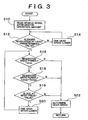
- a drive power control as described below is performed by the hybrid ECU 11.
- the hybrid ECU 11 reads a vehicle speed and an accelerator operation amount in S10, and then selects a gear speed (for a high speed) of a least gear ratio that allows at least a predetermined value of engine revolution speed in S12 and S14.
- the predetermined value (engine revolution speed lower limit) is set to a low value within a range in which engine torque fluctuation does not adversely affect the vehicle behavior, vibration, etc. For example, the predetermined value is set to about 1200 rpm. More specifically, it is determined in S12 whether the engine revolution speed is at least the predetermined value. If NO in S12, the gear speed is shifted to the next gear speed toward the low speed (in a gear ratio increasing direction) in S14. The process then returns to S12. If YES in S12, the process proceeds to S16.
- the gear speed set in S12 and S14 will be referred to as "provisionally set gear speed”.
- a requested drive power it is determined whether a requested drive power can be achieved singly by engine output.
- the requested drive power is determined based on the accelerator operation amount and the vehicle speed.
- the vehicle speed read in S10 and the provisionally set gear speed set in S12 and S14 are used to determine an engine revolution speed occurring when the provisionally set gear speed is adopted. Then, a maximum engine torque Temax corresponding to the engine revolution speed is determined. The value Temax is obtained by conversion into torque that acts on a drive shaft.
- the maximum engine torque Temax is set to a value at which the engine energy efficiency maximizes. That is, if the engine torque is increased while a certain engine revolution is maintained, the energy efficiency gradually increases to a maximum. If the engine torque is further increased, the energy efficiency decreases. The value Temax is set to this maximum point.
- the requested drive power is compared with the value Temax. If the value Temax is greater than or equal to the requested drive power, the requested drive power can be achieved singly by engine output. That is, if the determination in S16 is negative, the process proceeds to S22, in which a gear speed is determined. The gear speed selected in S12 and S14 is adopted without changing it. Then, the hybrid ECU 11 causes the engine 3 to produce the requested drive power.
- the determination in S16 becomes affirmative.
- the engine revolution speed occurring when the provisionally set gear speed is determined, and a maximum motor torque Tmmax is determined.
- the value Tmmax is also a value obtained by conversion into torque that acts on the drive shaft.
- the requested drive power is compared with Temax+Tmmax. If Temax+Tmmax is greater than or equal to the requested drive power, the requested drive power can be achieved by engine output and motor output. That is, if the determination in S18 is negative, the process proceeds to S22, in which a gear speed is determined. The gear speed selected in S12 and S14 is adopted without changing it. Then, the hybrid ECU 11 causes the engine 3 and the motor-generator 5 to produce the requested drive power. In this step, the hybrid ECU 11 causes the engine 3 to produce the maximum torque Temax, and causes the motor-generator 5 to produce a drive power that cannot be covered by the maximum torque of the engine 3, that is, a drive power equal to the shortfall from the requested drive power.
- step S18 If the requested drive power cannot be achieved even by the combination of engine output and motor output, the determination in S18 becomes affirmative.
- the process subsequently proceeds to S20, in which the gear speed is changed to the next gear speed toward the low gear side (toward the gear ratio increasing side). That is, in S20, the provisionally set gear speed set in S12 and S14 is changed by one gear speed. Subsequently, the process proceeds to step S16 to repeat similar processing.
- a priority sequence in the drive power adjusting control is determined as in the sequence of engine output, motor output, and gear speed, in this embodiment.
- the requested drive power is achieved through adjustment in accordance with the priority sequence. More specifically, a gear speed of a smallest possible gear ratio is provisionally set. If the requested drive power can be provided by engine output with the provisionally set gear speed, engine output is used. If the requested drive power is higher, torque assist by the electric motor is performed. If the requested drive power is even higher, the transmission is shifted to a lower-speed gear.
- the gear speed is set to a lower speed, and the engine torque is set to a higher value. Therefore, the engine can be highly efficiently operated in a low-speed and high-load state, thereby improving fuel economy.
- the hybrid ECU 11 changes the transmission speed based on factors that affect the motor control and, in particular, a factor that has effect on the amount of torque assist provided by the motor-generator 5.
- the factors having effect on the amount of torque assist include, for example, SOC (state of charge of a battery), battery temperature, inverter temperature, etc. It is to be noted that, depending on the values of these parameters, the torque that can be supplied from the side of the motor increases or decreases. Taking such changes in the torque, a gear speed of the transmission is set in this embodiment.
- FIG. 3 illustrates a control process in accordance with this embodiment, wherein SOC is used as a factor that affects the amount of torque assist.
- the process illustrated in FIG. 3 includes the control process illustrated in FIG. 2 , and also S19 following S18.
- S19 the SOC of the battery is determined.
- the SOC is expressed by, for example, the ratio of the amount of electricity stored at the time of performance of this control process to the amount of electricity stored in a full storage state.
- the SOC is determined by using battery voltage and current and, preferably, by also using battery temperature as needed. It is also possible to input an SOC determined by a separate battery ECU or the like into the hybrid ECU.
- the SOC at the time of performance of this control process is compared with a preset value. If the SOC is at most the preset value (i.e., if the SOC is equal to or less than the preset value), the process proceeds to S20, in which the gear speed is changed to the next speed toward the low speed side. If it is determined in S19 that the SOC is greater than the preset value, the process proceeds to S22, in which the gear speed is determined.
- this embodiment sets a gear speed based on a factor that has effect on the amount of torque assist or the torque assist capability of the motor-generator 5. Therefore, it becomes possible to secure a stable assist torque supplying capability and prevent a reduction in vehicle dynamics caused by an insufficient torque. Furthermore, it becomes possible to prevent deterioration of the battery or the like.
- the constructions of a hybrid vehicle and its control apparatus may be substantially the same as those in the first embodiment.
- the control process executed by the hybrid ECU 11 is improved, so that efficiency and fuel economy can be further improved.
- the hybrid ECU 11 selects a gear speed of a least gear ratio (a higher gear speed) within such a range that the requested drive power can be achieved by engine output and motor output while the present vehicle speed is maintained. Then, with the selected gear speed, the engine is operated in a predetermined high-efficiency operating state. The difference between the engine output and the requested drive power is compensated by drive power assist based on an electric power consuming movement (driving) of the motor, or, in the case of a surplus of power (from the engine), is regenerated into an electric power by electric power regenerating operation of the motor.
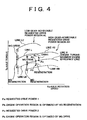
- FIG. 4 is a diagram indicating a specific example of the control process in this embodiment, in which the horizontal axis indicates axle rotation speed Np and the vertical axis indicates axle torque Tp.
- a requested drive power region AL achievable by a low gear and a requested drive power region AH achievable by a high gear are indicated.
- a central line L indicates engine torque (converted into axle torque; the same applies in the following description) produced when the engine is operated at a maximum efficiency with the low gear being set.
- a region upper limit line LU is located higher than the line L by a maximum value of motor drive torque.
- a region lower limit line LB is located lower than the line L by a maximum value of motor regenerative torque.
- the region AL is defined as a range such that the requested drive power can be achieved with the low gear.
- a central line H indicates engine torques produced when the engine is operated at a maximum efficiency with the high gear being set.
- a region upper limit line HU is located higher than the line H by a maximum value of motor drive torque.
- a region lower limit line HB is located lower than the line H by a maximum value of motor regenerative torque.
- the hybrid ECU 11 controls the transmission, the engine, and the motor as follows. That is, as described above, the hybrid ECU 11 selects a gear speed of a least gear ratio within the range such that the requested drive power can be achieved by engine output (maximum-efficiency operation) and motor output at the present vehicle speed.
- the combination of the requested drive power and the axle rotation speed is at a point Pa in FIG. 4 .
- the point Pa is contained only in the high gear-achievable requested drive power range AH. Therefore, the high gear is selected.
- the combination of the requested drive power and the axle rotation speed is at a point Pc in FIG. 4 .
- the point PC belongs to both the region AL and the region AH, so that either gear can be selected.
- the hybrid ECU 11 selects the gear speed of the less gear ratio, that is, the high gear.
- the aforementioned gear speed selecting process can be expressed by using expression (1): Temax i ⁇ v - Tm regenerative max i ⁇ v ⁇ requested drive power ⁇ Temax i ⁇ v + Tm drive max i ⁇ v
- Temax (i, v) is a torque (converted into an axle torque; the same applies hereinafter) produced during the maximum-efficiency operating state of the engine at the gear speed i and the vehicle speed v.
- Tm regenerative max (i, v) and Tm drive max (i, v) are a maximum value of regenerative torque and a maximum value of drive torque at the gear speed i and the vehicle speed v (however, if the motor is provided at the wheel side of the transmission, the motor torque is not affected by the gear ratio).
- a gear speed i of a least gear ratio that satisfies expression (1) is selected.
- the flow of the gear selecting process may be substantially the same as the flow illustrated in FIG. 2 . That is, based on the vehicle speed, a gear speed of a least gear ratio that provides an engine revolution speed that is higher than or equal to a predetermined lower-limit revolution speed is provisionally set. If expression (1) is satisfied at the provisionally set gear speed, the gear speed is immediately adopted. If the expression is not satisfied, the gear speed is changed to the next gear speed toward the low speed side. This process is continued until expression (1) is satisfied. As a result, a highest gear speed that allows for the requested drive power is selected.
- the number of gear speeds is two
- a similar gear selecting process is applicable to a transmission having more than two gear speeds.
- the combination of the requested drive power and the axle rotation speed is at a point Pa in the example of FIG. 4 .
- the engine is operated at a point Pb on the line H.
- the line H indicates torques output during the maximum-efficiency operating state of the engine with the high gear, as mentioned above. Since the engine output is greater than the requested drive power, the difference therebetween is absorbed by the regenerative operation of the motor. The electric power obtained by the regeneration is stored into the battery.
- the combination of the requested drive power and the axle rotation speed is at a point Pc in FIG. 4 .
- the engine is operated at a point Pd on the line H. Since the engine output is less than the requested drive power, the shortfall from the requested drive power is compensated by the drive operation of the motor. In this case, electric power is extracted from the battery.
- this embodiment selects an engine operation region and a gear speed so as to maximize the engine efficiency with the aid of the regenerative operation of the motor-generator or the drive operation of the motor-generator. Therefore, the embodiment is able to operate the engine at high efficiency and improve fuel economy.
- an engine operation region and a gear speed are selected such that the engine is operated at a maximum efficiency.
- an engine operation region and a gear speed are selected such that the multiplication product of the engine efficiency and the transmission rate of the transmission apparatus maximizes.
- the line H prescribes the output torque during the maximum-efficiency operating state of the engine.
- a line where the "engine efficiency ⁇ transmission rate of the transmission apparatus" maximizes is used in this modification.
- the transmission rate of the transmission apparatus is determined in accordance with the gear speed and the axle rotation speed.
- This embodiment is able to achieve maximum-efficiency operation of not only the engine but also the transmission system, and therefore allow a further improvement in fuel economy.
- an engine operation region and a gear speed are selected such that the emission characteristic is optimized. That is, taking it into consideration that emissions vary depending on the engine operation region, an operation region is selected such that the emission characteristic becomes good.
- the engine of the hybrid vehicle is assumed to be a diesel engine.
- the emission characteristic is bad in extracting a portion of exhaust gas from the exhaust system of the engine and returning the portion of exhaust gas to the intake system. Therefore, this region is avoided in selecting an engine operation region and a gear speed.
- this embodiment sets a gear speed of the transmission and an operation region of the engine so as to avoid the emission deterioration region, that is, so that the engine is operated in a good emission region. Therefore, the emission characteristic can be improved.
- regenerative braking is basically performed by the motor-generator, and the obtained electric power is stored into the battery.
- the invention is intended for a transmission-equipped hybrid vehicle.
- the invention sets a gear speed on the side of the transmission so that the efficiency of the regenerative braking on the side of the motor maximizes.
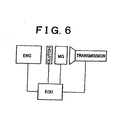
- This embodiment is applied to, for example, a control apparatus for a hybrid vehicle as illustrated in FIG. 6 .
- a motor-generator is disposed between an engine and a transmission.
- a clutch is interposed between a rotating shaft of the motor and a rotating shaft of the engine.
- the control apparatus determines whether the engine is turning or is stopped. If the clutch is connected, the engine is operating in a fuel-cut state. Conversely, if the clutch is disconnected, the engine is stopped.
- the control apparatus selects a gear speed of a least gear ratio. Therefore, the amount of engine turning resistance transmitted decreases, and the efficiency of regenerative braking increases. Conversely, when the engine is stopped, a gear speed that maximizes the efficiency of the motor-generator is selected. If the engine is stopped, there is no effect caused by engine turning resistance. Therefore, the aforementioned gear speed selection maximizes the efficiency of regenerative braking.
- the control apparatus controls the shift to the gear speed selected as described above. Furthermore, the control apparatus causes the motor-generator to perform regenerative braking.
- this embodiment sets a different gear speed depending on whether to operate or stop the engine, so that the efficiency of regenerative braking can be increased in both modes. Therefore, fuel economy and emission characteristic can be improved.
- the invention makes it possible to select an appropriate gear speed at which the engine and the motor can be efficiency operated in a transmission-equipped hybrid vehicle. Therefore, improvements can be achieved in efficiency, emissions, vehicle dynamics, etc.
- control means is implemented as a programmed general purpose computer. It will be appreciated by those skilled in the art that the control means can be implemented using a single special purpose integrated circuit (e.g., ASIC) having a main or central processor section for overall, system-level control, and separate sections dedicated to performing various different specific computations, functions and other processes under control of the central processor section.
- the control means also can be a plurality of separate dedicated or programmable integrated or other electronic circuits or devices (e.g., hardwired electronic or logic circuits such as discrete element circuits, or programmable logic devices such as PLDs, PLAs, PALs or the like).
- the control means can be implemented using a suitably programmed general purpose computer, e.g., a microprocessor, microcontroller or other processor device (CPU or MPU), either alone or in conjunction with one or more peripheral (e.g., integrated circuit) data and signal processing devices.
- a suitably programmed general purpose computer e.g., a microprocessor, microcontroller or other processor device (CPU or MPU), either alone or in conjunction with one or more peripheral (e.g., integrated circuit) data and signal processing devices.
- CPU or MPU processor device
- peripheral e.g., integrated circuit
Description
- The invention relates to a control apparatus according to the preamble of
claim 1 for a transmission-equipped hybrid vehicle having an engine, an electric motor, and a transmission. More particularly, the invention relates to a control apparatus that improve fuel efficiency, emission characteristics, dynamics, etc. - A hybrid vehicle has an engine and an electric motor as drive power sources. The electric motor is preferably used not only to produce vehicle-driving torque but also as an electric power generator. In this respect, the electric motor is often termed motor-generator. The hybrid vehicle is able to improve fuel economy and the like by efficiently operating the engine and the electric motor.
- A mechanical distribution type hybrid vehicle in which an engine and two electric motors are connected to a planetary gear unit has now been commercialized. This type of hybrid vehicle does not have a transmission. In contrast, a hybrid vehicle in which an engine, an electric motor, and a transmission are connected has also been proposed, as disclosed in, for example,
JP-A-0 8-168104 - In the aforementioned mechanical distribution type hybrid apparatus, optimization in terms of fuel economy and the like is pursued by controlling the operation states of the engine and the electric motors. However, this type of hybrid apparatus does not have a transmission for selecting from gear speeds.
- With regard to a vehicle that is not a hybrid vehicle, speed change characteristics of the automatic transmission are set so as to correspond to the vehicle speed and the amount of accelerator operation. Based on the speed change characteristics, a gear speed of the transmission is determined. A generally termed MMT (multi-mode manual transmission, that is, a transmission system where a clutch pedal is removed and clutch connecting/disconnecting operations are automatically performed by an actuator) also uses the speed change characteristics of the automatic transmission in a similar fashion to determine a gear speed.
- A transmission-equipped hybrid vehicle as mentioned above can be constructed by adding to a system in which an engine and a transmission are connected as mentioned above, an electric motor that produces torque to add to the drive power of the engine. However, if the speed change characteristics of an automatic transmission intended only for use with a conventional engine are immediately applied to the transmission-equipped hybrid vehicle although the electric motor is added to the hybrid vehicle, it is impossible to select a gear speed that allows most efficient operation, and it is difficult to perform appropriate controls regarding efficiency, emissions, vehicle dynamics, etc.
-
EP 913 287 A -
US 5 720 690 A discloses a similar control apparatus according to the preamble ofclaim 1. - Accordingly, it is one object of the invention to further develop a control apparatus according to the preamble of
claim 1 such that it is capable of appropriately controlling a hybrid vehicle having a transmission in terms of efficiency, emission characteristics, vehicle dynamics, etc. - This object is solved by an apparatus according to the
patent claim 1. - Further advantageous developments are defined in the dependent claims.
- Therefore, the invention provides a control apparatus for a hybrid vehicle having an engine and a motor as vehicle drive power sources and having, between the engine and a drive wheel, a transmission capable of changing drive power transmission by selection from a plurality of gear speeds. When the drive power requested for the vehicle is negative, a gear speed of the transmission is set such that an efficiency of regenerative braking performed by the motor maximizes.
- In a hybrid vehicle equipped with a transmission, the efficiency of the motor regenerative braking changes in accordance with the gear speed of the transmission. For example, when the engine is turned following the motor (i.e., when the engine is turned by the motor), selection of a less gear ratio reduces the turning resistance on the side of the engine, and therefore increases the regenerative braking efficiency on the side of the motor. Taking this fact into consideration, the apparatus of this aspect of the invention selects a gear speed such that the efficiency of regenerative braking maximizes. Therefore, improvements can be achieved in fuel economy and emissions.
- The gear speed selectedvaries in accordance with whether an operation of the engine is stopped or not during a regenerative operation of the motor. This aspect is intended for a construction in which the engine operation can be stopped by a clutch or the like. When the engine is turning, the turning resistance on the side of the engine decreases and the regenerative braking efficiency on the side of the motor increases with decreases in the gear ratio as stated above. When the engine is not turning, the turning resistance on the side of the engine does not need to be taken into consideration, so that a gear speed such that the efficiency on the side of the motor increases is selected. Thus, by selecting different gear speeds in accordance with whether the engine is turning or not, further improvements can be achieved in fuel economy and emissions.
- The foregoing object, and further features and advantages of the invention will become apparent from the following description of preferred embodiments with reference to the accompanying drawings, in which like numerals are used to represent like elements and wherein:
-
FIG. 1 is a block diagram illustrating an overall construction of a hybrid vehicle in accordance with an embodiment not forming part of the invention; -
FIG. 2 is a flowchart illustrating a control process executed by a hybrid ECU shown inFIG. 1 ; -
FIG. 3 is a flowchart illustrating a second embodiment not forming part of the invention of the control process executed by the hybrid ECU shown inFIG. 1 ; -
FIG. 4 is a diagram indicating a control process of a hybrid vehicle in accordance with another embodiment not forming part of the invention; -
FIG. 5 is a diagram indicating a modification of the control process illustrated inFIG. 4 ; and -
FIG. 6 is a diagram of a hybrid vehicle for illustrating an example of the control process executed when the requested drive power with respect to the vehicle is negative. -
FIG. 1 is a block diagram of a construction of a direct-coupled hybrid vehicle equipped with a transmission. Ahybrid vehicle 1 has anengine 3 and a motor-generator 5 as drive power sources. Theengine 3 and the motor-generator 5 are interconnected. The motor-generator 5 is connected to anautomatic transmission 7. Theautomatic transmission 7 is connected to drive wheels (not shown). The motor-generator 5, when functioning as an electric motor, receives electric power from abattery 9 to produce drive power. When functioning as an electric power generator, the motor-generator 5 is turned by output from the engine to generate electric power, and sends the generated power to thebattery 9. - Within the scope of the invention, the motor-
generator 5 is not restricted by the layout shown inFIG. 1 . For example, the motor-generator 5 may be provided at a drive wheel-side of theautomatic transmission 7. Furthermore, the motor-generator 5 may be connected to an engine output shaft or the like, or to an input/output shaft of the transmission or the like, via a clutch. - Still further, a generally termed MMT (multi-mode manual transmission) may be disposed in place of the
automatic transmission 7. Unlike a conventional manual transmission, the MMT does not employ a clutch pedal but has an actuator for automatically performing clutch operations for a driving person. Based on mode settings, the MMT automatically determines a gear speed through the use of a control apparatus, as is the case with an automatic transmission. Thus, the invention is applicable not only to automatic transmissions but also to any other transmission in a similar fashion as long as the transmission is capable of selecting a gear speed from a plurality of gear speeds. - The
engine 3, the motor-generator 5 and theautomatic transmission 7 are controlled by ahybrid ECU 11. The hybrid ECU 11 may be formed by either a single computer or a plurality of computers. For example, anengine control portion 13, a motor-generator control portion 15, and an automatictransmission control portion 17 may be formed by three separate ECUs. - The
hybrid ECU 11 receives input of an amount of accelerator operation performed by a driving person from anaccelerator sensor 21, input of vehicle speed from avehicle speed sensor 23, input of engine revolution speed from an enginerevolution speed sensor 27, and input of a detection signal indicating a state of charge of the battery from abattery sensor 25. Using such input information, thehybrid ECU 11 appropriately operates theengine 3, the motor-generator 5, and theautomatic transmission 7 based on the running state of the vehicle, the operation performed by the driving person, and the state of charge of the battery. - Let it be assumed herein that the system shown in
FIG. 1 is not provided with a motor-generator. In this case, controls may be performed as in a conventional automatic transmission-equipped vehicle that is not a hybrid vehicle. That is, a speed change map set in accordance with the vehicle speed and the amount of accelerator operation is pre-stored. In accordance with the speed change map, a gear speed is determined, and the transmission is controlled. - In this embodiment, a motor-generator as a torque assist device is added. Therefore, if the automatic transmission is controlled through the use of a conventional speed change map, high-efficiency operation of the hybrid vehicle cannot be performed. For example, let it be assumed that the driving person suddenly depresses an accelerator pedal so that a considerable increase in the vehicle drive power is requested. In this case, it is conceivable to increase the motor output or perform a downshift of gears in the construction shown in
FIG. 1 . In this invention, a drive power control is performed by adjusting and controlling theengine 3, the motor-generator 5, and theautomatic transmission 7 corresponding to the requested drive power of the vehicle. In this embodiment, a drive power control as described below is performed by thehybrid ECU 11. - Referring to
FIG. 2 , thehybrid ECU 11 reads a vehicle speed and an accelerator operation amount in S10, and then selects a gear speed (for a high speed) of a least gear ratio that allows at least a predetermined value of engine revolution speed in S12 and S14. The predetermined value (engine revolution speed lower limit) is set to a low value within a range in which engine torque fluctuation does not adversely affect the vehicle behavior, vibration, etc. For example, the predetermined value is set to about 1200 rpm. More specifically, it is determined in S12 whether the engine revolution speed is at least the predetermined value. If NO in S12, the gear speed is shifted to the next gear speed toward the low speed (in a gear ratio increasing direction) in S14. The process then returns to S12. If YES in S12, the process proceeds to S16. The gear speed set in S12 and S14 will be referred to as "provisionally set gear speed". - In S16, it is determined whether a requested drive power can be achieved singly by engine output. The requested drive power is determined based on the accelerator operation amount and the vehicle speed. In this flowchart, the vehicle speed read in S10 and the provisionally set gear speed set in S12 and S14 are used to determine an engine revolution speed occurring when the provisionally set gear speed is adopted. Then, a maximum engine torque Temax corresponding to the engine revolution speed is determined. The value Temax is obtained by conversion into torque that acts on a drive shaft.
- In this embodiment, the maximum engine torque Temax is set to a value at which the engine energy efficiency maximizes. That is, if the engine torque is increased while a certain engine revolution is maintained, the energy efficiency gradually increases to a maximum. If the engine torque is further increased, the energy efficiency decreases. The value Temax is set to this maximum point.
- In S16, the requested drive power is compared with the value Temax. If the value Temax is greater than or equal to the requested drive power, the requested drive power can be achieved singly by engine output. That is, if the determination in S16 is negative, the process proceeds to S22, in which a gear speed is determined. The gear speed selected in S12 and S14 is adopted without changing it. Then, the
hybrid ECU 11 causes theengine 3 to produce the requested drive power. - If the requested drive power cannot be achieved singly by engine output, the determination in S16 becomes affirmative. Subsequently in S18, it is determined whether the requested drive power can be achieved by engine output and motor output. In this step, the engine revolution speed occurring when the provisionally set gear speed is determined, and a maximum motor torque Tmmax is determined. The value Tmmax is also a value obtained by conversion into torque that acts on the drive shaft.
- In S18, the requested drive power is compared with Temax+Tmmax. If Temax+Tmmax is greater than or equal to the requested drive power, the requested drive power can be achieved by engine output and motor output. That is, if the determination in S18 is negative, the process proceeds to S22, in which a gear speed is determined. The gear speed selected in S12 and S14 is adopted without changing it. Then, the
hybrid ECU 11 causes theengine 3 and the motor-generator 5 to produce the requested drive power. In this step, thehybrid ECU 11 causes theengine 3 to produce the maximum torque Temax, and causes the motor-generator 5 to produce a drive power that cannot be covered by the maximum torque of theengine 3, that is, a drive power equal to the shortfall from the requested drive power. - If the requested drive power cannot be achieved even by the combination of engine output and motor output, the determination in S18 becomes affirmative. The process subsequently proceeds to S20, in which the gear speed is changed to the next gear speed toward the low gear side (toward the gear ratio increasing side). That is, in S20, the provisionally set gear speed set in S12 and S14 is changed by one gear speed. Subsequently, the process proceeds to step S16 to repeat similar processing.
- As can be understood from the foregoing description, a priority sequence in the drive power adjusting control is determined as in the sequence of engine output, motor output, and gear speed, in this embodiment. The requested drive power is achieved through adjustment in accordance with the priority sequence. More specifically, a gear speed of a smallest possible gear ratio is provisionally set. If the requested drive power can be provided by engine output with the provisionally set gear speed, engine output is used. If the requested drive power is higher, torque assist by the electric motor is performed. If the requested drive power is even higher, the transmission is shifted to a lower-speed gear.
- Through this control, the gear speed is set to a lower speed, and the engine torque is set to a higher value. Therefore, the engine can be highly efficiently operated in a low-speed and high-load state, thereby improving fuel economy.
- Furthermore, until the motor torque reaches a maximum, the requested drive power is achieved through torque assist by the motor without a downshift of the gear speed. Therefore, frequent downshifts are avoided, so that drivability can be improved. Still further, if the number of downshifts is small, the influence of sharp changes in engine revolution speed due to downshifts on emissions (problem in the AF controllability) can be reduced, so that an improvement can be achieved in emissions.
- Next, a preferred control process executed by the
hybrid ECU 11 in this embodiment will be described. In this process, thehybrid ECU 11 changes the transmission speed based on factors that affect the motor control and, in particular, a factor that has effect on the amount of torque assist provided by the motor-generator 5. - The factors having effect on the amount of torque assist include, for example, SOC (state of charge of a battery), battery temperature, inverter temperature, etc. It is to be noted that, depending on the values of these parameters, the torque that can be supplied from the side of the motor increases or decreases. Taking such changes in the torque, a gear speed of the transmission is set in this embodiment.
-
FIG. 3 illustrates a control process in accordance with this embodiment, wherein SOC is used as a factor that affects the amount of torque assist. The process illustrated inFIG. 3 includes the control process illustrated inFIG. 2 , and also S19 following S18. In S19, the SOC of the battery is determined. The SOC is expressed by, for example, the ratio of the amount of electricity stored at the time of performance of this control process to the amount of electricity stored in a full storage state. The SOC is determined by using battery voltage and current and, preferably, by also using battery temperature as needed. It is also possible to input an SOC determined by a separate battery ECU or the like into the hybrid ECU. - In S19, the SOC at the time of performance of this control process is compared with a preset value. If the SOC is at most the preset value (i.e., if the SOC is equal to or less than the preset value), the process proceeds to S20, in which the gear speed is changed to the next speed toward the low speed side. If it is determined in S19 that the SOC is greater than the preset value, the process proceeds to S22, in which the gear speed is determined.
- Thus, this embodiment sets a gear speed based on a factor that has effect on the amount of torque assist or the torque assist capability of the motor-
generator 5. Therefore, it becomes possible to secure a stable assist torque supplying capability and prevent a reduction in vehicle dynamics caused by an insufficient torque. Furthermore, it becomes possible to prevent deterioration of the battery or the like. - Another embodiment will next be described. In this embodiment, the constructions of a hybrid vehicle and its control apparatus may be substantially the same as those in the first embodiment. In the second embodiment, the control process executed by the
hybrid ECU 11 is improved, so that efficiency and fuel economy can be further improved. - In this embodiment, the
hybrid ECU 11 selects a gear speed of a least gear ratio (a higher gear speed) within such a range that the requested drive power can be achieved by engine output and motor output while the present vehicle speed is maintained. Then, with the selected gear speed, the engine is operated in a predetermined high-efficiency operating state. The difference between the engine output and the requested drive power is compensated by drive power assist based on an electric power consuming movement (driving) of the motor, or, in the case of a surplus of power (from the engine), is regenerated into an electric power by electric power regenerating operation of the motor. -
FIG. 4 is a diagram indicating a specific example of the control process in this embodiment, in which the horizontal axis indicates axle rotation speed Np and the vertical axis indicates axle torque Tp. In the diagram, a requested drive power region AL achievable by a low gear and a requested drive power region AH achievable by a high gear are indicated. - In the region AL, a central line L indicates engine torque (converted into axle torque; the same applies in the following description) produced when the engine is operated at a maximum efficiency with the low gear being set. A region upper limit line LU is located higher than the line L by a maximum value of motor drive torque. A region lower limit line LB is located lower than the line L by a maximum value of motor regenerative torque. In this embodiment, the region AL is defined as a range such that the requested drive power can be achieved with the low gear. In the high gear-achievable requested drive power region AH, a central line H indicates engine torques produced when the engine is operated at a maximum efficiency with the high gear being set. A region upper limit line HU is located higher than the line H by a maximum value of motor drive torque. A region lower limit line HB is located lower than the line H by a maximum value of motor regenerative torque. It should be noted herein that the region AH of the high gear and the region AL of the low gear have different shapes and positions corresponding to their different gear ratios.
- In the example indicated in
FIG. 4 , thehybrid ECU 11 controls the transmission, the engine, and the motor as follows. That is, as described above, thehybrid ECU 11 selects a gear speed of a least gear ratio within the range such that the requested drive power can be achieved by engine output (maximum-efficiency operation) and motor output at the present vehicle speed. - For example, let it be assumed that the combination of the requested drive power and the axle rotation speed (vehicle speed) is at a point Pa in
FIG. 4 . In this case, the point Pa is contained only in the high gear-achievable requested drive power range AH. Therefore, the high gear is selected. - Furthermore, let it be assumed that the combination of the requested drive power and the axle rotation speed is at a point Pc in
FIG. 4 . In this case, the point PC belongs to both the region AL and the region AH, so that either gear can be selected. Thehybrid ECU 11 selects the gear speed of the less gear ratio, that is, the high gear. - The aforementioned gear speed selecting process can be expressed by using expression (1):

- Temax (i, v) is a torque (converted into an axle torque; the same applies hereinafter) produced during the maximum-efficiency operating state of the engine at the gear speed i and the vehicle speed v. Tm regenerative max (i, v) and Tm drive max (i, v) are a maximum value of regenerative torque and a maximum value of drive torque at the gear speed i and the vehicle speed v (however, if the motor is provided at the wheel side of the transmission, the motor torque is not affected by the gear ratio). In this embodiment, a gear speed i of a least gear ratio that satisfies expression (1) is selected.
- The flow of the gear selecting process may be substantially the same as the flow illustrated in
FIG. 2 . That is, based on the vehicle speed, a gear speed of a least gear ratio that provides an engine revolution speed that is higher than or equal to a predetermined lower-limit revolution speed is provisionally set. If expression (1) is satisfied at the provisionally set gear speed, the gear speed is immediately adopted. If the expression is not satisfied, the gear speed is changed to the next gear speed toward the low speed side. This process is continued until expression (1) is satisfied. As a result, a highest gear speed that allows for the requested drive power is selected. - Although in the example indicated in
FIG. 4 , the number of gear speeds is two, a similar gear selecting process is applicable to a transmission having more than two gear speeds. - An engine control and a motor control at the selected gear speed will next be described. In this embodiment, the engine is operated in a high-efficiency operating state, and the difference between the engine output and the requested drive power is compensated by the drive operation of the motor or the regenerative operation of the motor as mentioned above.
- For a specific description, let it be assumed that the combination of the requested drive power and the axle rotation speed is at a point Pa in the example of
FIG. 4 . In this case, the engine is operated at a point Pb on the line H. The line H indicates torques output during the maximum-efficiency operating state of the engine with the high gear, as mentioned above. Since the engine output is greater than the requested drive power, the difference therebetween is absorbed by the regenerative operation of the motor. The electric power obtained by the regeneration is stored into the battery. - Furthermore, let it be assumed that the combination of the requested drive power and the axle rotation speed is at a point Pc in
FIG. 4 . In this case, the engine is operated at a point Pd on the line H. Since the engine output is less than the requested drive power, the shortfall from the requested drive power is compensated by the drive operation of the motor. In this case, electric power is extracted from the battery. - As is apparent from the foregoing description, this embodiment selects an engine operation region and a gear speed so as to maximize the engine efficiency with the aid of the regenerative operation of the motor-generator or the drive operation of the motor-generator. Therefore, the embodiment is able to operate the engine at high efficiency and improve fuel economy.
- A modification of the foregoing embodiment will be described. In the foregoing embodiment, an engine operation region and a gear speed are selected such that the engine is operated at a maximum efficiency. In this modification, an engine operation region and a gear speed are selected such that the multiplication product of the engine efficiency and the transmission rate of the transmission apparatus maximizes.
- In the example indicated in
FIG. 4 , the line H prescribes the output torque during the maximum-efficiency operating state of the engine. Instead of the line H, a line where the "engine efficiency × transmission rate of the transmission apparatus" maximizes is used in this modification. The transmission rate of the transmission apparatus is determined in accordance with the gear speed and the axle rotation speed. - This embodiment is able to achieve maximum-efficiency operation of not only the engine but also the transmission system, and therefore allow a further improvement in fuel economy.
- Another modification of the embodiment will be described. In this modification, an engine operation region and a gear speed are selected such that the emission characteristic is optimized. That is, taking it into consideration that emissions vary depending on the engine operation region, an operation region is selected such that the emission characteristic becomes good.
- In a specific example indicated in
FIG. 5 , the engine of the hybrid vehicle is assumed to be a diesel engine. As indicated inFIG. 5 , in a low-speed and high-load region of a diesel engine, there is a region where the emission characteristic is bad in extracting a portion of exhaust gas from the exhaust system of the engine and returning the portion of exhaust gas to the intake system. Therefore, this region is avoided in selecting an engine operation region and a gear speed. - For example, let it be assumed that the combination of the axle rotation speed and the requested drive power is at a point Pe in
FIG. 5 . If the engine is operated at a maximum-efficiency point (Pf on the line H), the operation point enters the emission deterioration region. To avoid this, a point Pg indicated in the diagram is selected as an operation region. In this case, the engine output is insufficient for the requested drive power, so that the amount of shortfall is compensated by motor output (drive). - As is apparent from the foregoing description, this embodiment sets a gear speed of the transmission and an operation region of the engine so as to avoid the emission deterioration region, that is, so that the engine is operated in a good emission region. Therefore, the emission characteristic can be improved.
- While controls performed in a case where the requested drive power is mainly positive have been described above, a preferable control in a case where the requested drive power is negative will be described below.
- When the requested drive power is negative, regenerative braking is basically performed by the motor-generator, and the obtained electric power is stored into the battery. The invention is intended for a transmission-equipped hybrid vehicle. When the requested drive power is negative, the invention sets a gear speed on the side of the transmission so that the efficiency of the regenerative braking on the side of the motor maximizes.
- Next, an example of the transmission control performed when the requested drive power is negative will be described. A hybrid vehicle designed so as to be able to stop engine revolution is assumed herein. This embodiment according to the present invention selects a gear speed at which the regeneration efficiency maximizes. The optimal gear speed set varies depending on whether to stop engine operation.
- This embodiment is applied to, for example, a control apparatus for a hybrid vehicle as illustrated in
FIG. 6 . A motor-generator is disposed between an engine and a transmission. A clutch is interposed between a rotating shaft of the motor and a rotating shaft of the engine. - When the requested drive power is negative, the control apparatus determines whether the engine is turning or is stopped. If the clutch is connected, the engine is operating in a fuel-cut state. Conversely, if the clutch is disconnected, the engine is stopped.
- When the engine is operating, the control apparatus selects a gear speed of a least gear ratio. Therefore, the amount of engine turning resistance transmitted decreases, and the efficiency of regenerative braking increases. Conversely, when the engine is stopped, a gear speed that maximizes the efficiency of the motor-generator is selected. If the engine is stopped, there is no effect caused by engine turning resistance. Therefore, the aforementioned gear speed selection maximizes the efficiency of regenerative braking. The control apparatus controls the shift to the gear speed selected as described above. Furthermore, the control apparatus causes the motor-generator to perform regenerative braking.
- Thus, this embodiment sets a different gear speed depending on whether to operate or stop the engine, so that the efficiency of regenerative braking can be increased in both modes. Therefore, fuel economy and emission characteristic can be improved.
- As is apparent from the foregoing embodiment, the invention makes it possible to select an appropriate gear speed at which the engine and the motor can be efficiency operated in a transmission-equipped hybrid vehicle. Therefore, improvements can be achieved in efficiency, emissions, vehicle dynamics, etc.
- In the illustrated embodiment, the control means (hybrid ECU 11) is implemented as a programmed general purpose computer. It will be appreciated by those skilled in the art that the control means can be implemented using a single special purpose integrated circuit (e.g., ASIC) having a main or central processor section for overall, system-level control, and separate sections dedicated to performing various different specific computations, functions and other processes under control of the central processor section. The control means also can be a plurality of separate dedicated or programmable integrated or other electronic circuits or devices (e.g., hardwired electronic or logic circuits such as discrete element circuits, or programmable logic devices such as PLDs, PLAs, PALs or the like). The control means can be implemented using a suitably programmed general purpose computer, e.g., a microprocessor, microcontroller or other processor device (CPU or MPU), either alone or in conjunction with one or more peripheral (e.g., integrated circuit) data and signal processing devices. In general, any device or assembly of devices on which a finite state machine capable of implementing the procedures described herein can be used as the control means. A distributed processing architecture can be used for maximum data/signal processing capability and speed.
- While the invention has been described with reference to the preferred embodiment thereof, it is to be understood that the invention is not limited to the preferred embodiment or construction. On the contrary, the invention is intended to cover various modifications and equivalent arrangements. In addition, while the various elements of the preferred embodiments are shown in various combinations and configurations, which are exemplary, other combinations and configurations, including more, less or only a single element, are also within the scope of the invention.
Claims (3)
- A control apparatus having an engine (3) and a motor (5) as vehicle drive power sources and having, between the engine (3) and a vehicle drive wheel, a transmission (7) that changes drive power transmission by selection from a plurality of gear speeds, the control apparatus comprising:detection means (21, 23) for detecting a drive power requested for the vehicle; andcontrol means (11) for setting a gear speed of the transmission (7) such that an efficiency of regenerative braking performed by the motor (5) maximizes when the requested drive power is negative,characterized in thatthe gear speed selected varies in accordance with whether or not an operation of the engine (3) is at a stop during a regenerative operation of the motor (5).
- A control apparatus according to claim 1, wherein the control means (11) selects a gear speed of a least gear ratio during an operation of the engine (3).
- A control apparatus according to claim 1, wherein the control means (11) selects a gear speed such that a drive efficiency of the motor (5) maximizes during a stop of operation of the engine (3).
Applications Claiming Priority (3)
| Application Number | Priority Date | Filing Date | Title |
|---|---|---|---|
| JP32907899A JP2001146121A (en) | 1999-11-19 | 1999-11-19 | Control device for hybrid vehicle with transmission |
| JP32907899 | 1999-11-19 | ||
| EP00123650A EP1101650B1 (en) | 1999-11-19 | 2000-10-30 | Control apparatus for transmission-equipped hybrid vehicle |
Related Parent Applications (1)
| Application Number | Title | Priority Date | Filing Date |
|---|---|---|---|
| EP00123650A Division EP1101650B1 (en) | 1999-11-19 | 2000-10-30 | Control apparatus for transmission-equipped hybrid vehicle |
Publications (3)
| Publication Number | Publication Date |
|---|---|
| EP1555156A2 EP1555156A2 (en) | 2005-07-20 |
| EP1555156A3 EP1555156A3 (en) | 2006-02-01 |
| EP1555156B1 true EP1555156B1 (en) | 2008-08-27 |
Family
ID=18217387
Family Applications (2)
| Application Number | Title | Priority Date | Filing Date |
|---|---|---|---|
| EP00123650A Expired - Lifetime EP1101650B1 (en) | 1999-11-19 | 2000-10-30 | Control apparatus for transmission-equipped hybrid vehicle |
| EP05007783A Expired - Lifetime EP1555156B1 (en) | 1999-11-19 | 2000-10-30 | Control apparatus for transmission-equipped hybrid vehicle |
Family Applications Before (1)
| Application Number | Title | Priority Date | Filing Date |
|---|---|---|---|
| EP00123650A Expired - Lifetime EP1101650B1 (en) | 1999-11-19 | 2000-10-30 | Control apparatus for transmission-equipped hybrid vehicle |
Country Status (5)
| Country | Link |
|---|---|
| US (2) | US6867509B1 (en) |
| EP (2) | EP1101650B1 (en) |
| JP (1) | JP2001146121A (en) |
| CN (3) | CN100408368C (en) |
| DE (2) | DE60040105D1 (en) |
Families Citing this family (80)
| Publication number | Priority date | Publication date | Assignee | Title |
|---|---|---|---|---|
| US9193268B2 (en) * | 2001-03-27 | 2015-11-24 | General Electric Company | Hybrid energy power management system and method |
| JP3827980B2 (en) * | 2001-09-21 | 2006-09-27 | 本田技研工業株式会社 | Control device for hybrid vehicle |
| JP3666438B2 (en) * | 2001-10-11 | 2005-06-29 | 日産自動車株式会社 | Control device for hybrid vehicle |
| FR2833888B1 (en) * | 2001-12-20 | 2004-03-19 | Renault | METHOD FOR CONTROLLING A HYBRID DRIVE SYSTEM AND ASSOCIATED DRIVE SYSTEM |
| EP1356972B1 (en) * | 2002-04-08 | 2007-07-04 | Ford Global Technologies, LLC | Method for controlling a hybrid vehicle drivetrain |
| US20040034460A1 (en) * | 2002-08-13 | 2004-02-19 | Folkerts Charles Henry | Powertrain control system |
| DE10257285A1 (en) * | 2002-12-07 | 2004-06-24 | Robert Bosch Gmbh | Control circuit setting operating point for road vehicle drive-train uses mapping diagram with three-dimensional plot with several degrees of freedom and has several control modules connected together |
| JP3852402B2 (en) | 2002-12-25 | 2006-11-29 | トヨタ自動車株式会社 | Control device for hybrid drive |
| DE10318738A1 (en) * | 2003-04-25 | 2004-11-11 | Daimlerchrysler Ag | Control of an electric motor |
| JP3963868B2 (en) * | 2003-06-23 | 2007-08-22 | トヨタ自動車株式会社 | Control device for hybrid drive |
| US7216729B2 (en) * | 2003-09-19 | 2007-05-15 | Ford Global Technologies, Llc | Method and system of requesting engine on/off state in a hybrid electric vehicle |
| JP3928624B2 (en) * | 2004-03-12 | 2007-06-13 | トヨタ自動車株式会社 | Control device for hybrid vehicle |
| DE102004016473A1 (en) * | 2004-03-31 | 2005-10-20 | Bosch Gmbh Robert | Flow control of functions on interacting devices |
| US7090613B2 (en) * | 2004-05-15 | 2006-08-15 | General Motors Corporation | Method of providing electric motor torque reserve in a hybrid electric vehicle |
| JP4360492B2 (en) * | 2004-08-05 | 2009-11-11 | 本田技研工業株式会社 | Shift control device for continuously variable transmission in hybrid vehicle |
| CA2479890A1 (en) * | 2004-09-27 | 2006-03-27 | Samuel Beaudoin | High efficiency generator system and continuously variable transmission therefor |
| JP4301224B2 (en) * | 2005-02-16 | 2009-07-22 | トヨタ自動車株式会社 | Automobile and control method thereof |
| US7543454B2 (en) * | 2005-03-14 | 2009-06-09 | Zero Emission Systems, Inc. | Method and auxiliary system for operating a comfort subsystem for a vehicle |
| US7600595B2 (en) * | 2005-03-14 | 2009-10-13 | Zero Emission Systems, Inc. | Electric traction |
| JP4494266B2 (en) * | 2005-03-28 | 2010-06-30 | 三菱ふそうトラック・バス株式会社 | Shift control device for hybrid vehicle |
| JP2006275097A (en) * | 2005-03-28 | 2006-10-12 | Mitsubishi Fuso Truck & Bus Corp | Vehicular shift control device |
| JP4792817B2 (en) * | 2005-05-31 | 2011-10-12 | いすゞ自動車株式会社 | Automatic transmission control device |
| US7607505B2 (en) * | 2005-08-12 | 2009-10-27 | Tai-Her Yang | Energy storage type of differential mixed power distribution system |
| US7479091B2 (en) * | 2005-08-15 | 2009-01-20 | Tai-Her Yang | Engine running at fixed speed incorporated controllable transmission power system |
| DE102005047940A1 (en) * | 2005-10-06 | 2007-04-12 | Volkswagen Ag | Torque controlling method for e.g. passenger car, involves impressing combustion engine torque in one phase for specific time by electromotive torque so that resulted entire drive torque corresponds to desired torque |
| US7780562B2 (en) * | 2006-01-09 | 2010-08-24 | General Electric Company | Hybrid vehicle and method of assembling same |
| JP2007191097A (en) * | 2006-01-20 | 2007-08-02 | Fujitsu Ten Ltd | Vehicle control device and vehicle control method |
| DE102006004280A1 (en) * | 2006-01-31 | 2007-08-02 | Robert Bosch Gmbh | Process for continually monitoring the momentum of a hybrid drive comprises reducing the permissible total momentum by the actual momentum of an electric drive and creating a permissible momentum of an internal combustion engine |
| US7921945B2 (en) * | 2006-02-21 | 2011-04-12 | Clean Emissions Technologies, Inc. | Vehicular switching, including switching traction modes and shifting gears while in electric traction mode |
| US8668035B2 (en) | 2006-03-14 | 2014-03-11 | Clean Emissions Technologies, Inc. | Electric traction system and method |
| US8565969B2 (en) | 2007-04-03 | 2013-10-22 | Clean Emissions Technologies, Inc. | Over the road/traction/cabin comfort retrofit |
| DE102007011410A1 (en) * | 2006-03-14 | 2007-11-08 | Mitsubishi Fuso Truck and Bus Corp., Kawasaki | Control unit for a hybrid electric vehicle |
| US8323145B2 (en) * | 2006-03-29 | 2012-12-04 | GM Global Technology Operations LLC | Hybrid powertrain optimum ratio selection |
| US8050831B2 (en) * | 2006-04-07 | 2011-11-01 | Ford Global Technologies, Llc | Vehicle engine speed control for a continuously variable transmission |
| JPWO2008026480A1 (en) | 2006-08-30 | 2010-01-21 | アイシン精機株式会社 | Vehicle drive source control device |
| US7921950B2 (en) * | 2006-11-10 | 2011-04-12 | Clean Emissions Technologies, Inc. | Electric traction retrofit |
| JP4100445B1 (en) * | 2007-01-10 | 2008-06-11 | トヨタ自動車株式会社 | Hybrid drive apparatus, vehicle including the same, and control method thereof |
| JP5151160B2 (en) * | 2007-01-26 | 2013-02-27 | トヨタ自動車株式会社 | Control device for vehicle drive device |
| JP4379484B2 (en) * | 2007-04-06 | 2009-12-09 | 株式会社デンソー | Vehicle system |
| EP2003318B1 (en) * | 2007-06-14 | 2011-08-10 | Continental Automotive GmbH | A system for running an internal combustion engine |
| JP4238927B1 (en) * | 2007-09-07 | 2009-03-18 | トヨタ自動車株式会社 | Control device for automatic transmission for vehicle |
| US7792628B2 (en) * | 2007-09-27 | 2010-09-07 | Ford Global Technologies, Llc | Electrical assist for reducing emissions and torsion response delay in a hybrid electric vehicle |
| US8078371B2 (en) * | 2007-10-31 | 2011-12-13 | GM Global Technology Operations LLC | Method and apparatus to monitor output of an electro-mechanical transmission |
| US7726430B2 (en) * | 2007-12-04 | 2010-06-01 | Tai-Her Yang | Energy storage type of differential hybrid power distribution system |
| US9758146B2 (en) * | 2008-04-01 | 2017-09-12 | Clean Emissions Technologies, Inc. | Dual mode clutch pedal for vehicle |
| DE102008001159A1 (en) * | 2008-04-14 | 2009-10-15 | Robert Bosch Gmbh | Method and control module for controlling the drive mode of a hybrid drive to prevent jerking |
| US20090321156A1 (en) * | 2008-06-25 | 2009-12-31 | Ford Global Technologies, Llc | Hybrid automotive powertrain system and method of operating same |
| US8055422B2 (en) * | 2008-08-08 | 2011-11-08 | GM Global Technology Operations LLC | Vehicle deceleration rate control method and apparatus |
| US9168825B2 (en) * | 2009-05-15 | 2015-10-27 | Ford Global Technologies, Llc | Hybrid electric vehicle and method for controlling a powertrain therein |
| US8616312B2 (en) * | 2009-08-28 | 2013-12-31 | Eaton Corporation | Hybrid electric vehicle battery thermal management |
| US9631528B2 (en) | 2009-09-03 | 2017-04-25 | Clean Emissions Technologies, Inc. | Vehicle reduced emission deployment |
| WO2011039770A2 (en) | 2009-09-15 | 2011-04-07 | Kpit Cummins Infosystems Ltd. | Method of converting vehicle into hybrid vehicle |
| US8423214B2 (en) | 2009-09-15 | 2013-04-16 | Kpit Cummins Infosystems, Ltd. | Motor assistance for a hybrid vehicle |
| JP5774592B2 (en) | 2009-09-15 | 2015-09-09 | ケーピーアイティ テクノロジーズ リミテッド | Hybrid vehicle motor assistance based on predicted driving range |
| MX2012003116A (en) | 2009-09-15 | 2012-06-19 | Kpit Cummins Infosystems Ltd | Method of providing assistance for a hybrid vehicle based on user input. |
| US9296290B2 (en) * | 2010-03-26 | 2016-03-29 | Ford Global Technologies, Llc | Multiple-ratio transmission downshift strategy for hybrid electric vehicle powertrains |
| US9145048B2 (en) * | 2010-03-31 | 2015-09-29 | General Electric Company | Apparatus for hybrid engine control and method of manufacture same |
| KR101271477B1 (en) * | 2010-07-08 | 2013-06-05 | 한국체인공업 주식회사 | load sensing type automatic transmission system of electric vehicle for agricultural |
| US9403532B2 (en) * | 2010-07-09 | 2016-08-02 | Allison Transmission, Inc. | Closed-loop transmission integration with forward and/or reverse assist system |
| DE102011002541A1 (en) * | 2011-01-12 | 2012-07-12 | Zf Friedrichshafen Ag | Method for operating a hybrid drive and control device of a hybrid drive |
| US8676455B2 (en) * | 2011-02-15 | 2014-03-18 | Eaton Corporation | Methods and systems for selecting or maintaining an efficient gear or gear ratio |
| US8666577B2 (en) | 2012-04-26 | 2014-03-04 | Ford Global Technologies, Llc | Economic cruise control |
| US8897943B2 (en) * | 2013-03-15 | 2014-11-25 | Deere & Company | Battery electric hybrid drive for a combine harvester |
| WO2014174605A1 (en) | 2013-04-24 | 2014-10-30 | 三菱電機株式会社 | Transmission control device and transmission control method |
| US20150102752A1 (en) * | 2013-10-10 | 2015-04-16 | Electro-Motive Diesel, Inc. | Braking system for vehicle |
| US9637114B2 (en) | 2014-04-08 | 2017-05-02 | Ford Global Technologies, Llc | Step-ratio transmission control for a hybrid vehicle |
| US9403523B2 (en) * | 2014-08-13 | 2016-08-02 | Ford Global Technologies, Llc | Methods and systems for adjusting hybrid vehicle efficiency |
| JP6244477B2 (en) * | 2014-11-04 | 2017-12-06 | 本田技研工業株式会社 | Charge control device and charge control method |
| DE102015213580A1 (en) * | 2015-07-20 | 2017-01-26 | Siemens Aktiengesellschaft | Propeller drive and vehicle, in particular aircraft |
| JP6593044B2 (en) * | 2015-09-09 | 2019-10-23 | いすゞ自動車株式会社 | Hybrid vehicle and control method thereof |
| JP2017094829A (en) * | 2015-11-20 | 2017-06-01 | いすゞ自動車株式会社 | Hybrid vehicle and control method therefor |
| US20170174219A1 (en) * | 2015-12-18 | 2017-06-22 | Cnh Industrial America Llc | Auto-efficiency mode for power shift transmissions |
| US10000203B2 (en) | 2016-01-13 | 2018-06-19 | Ford Global Technologies, Llc | EV mode shift strategy for hybrid vehicle |
| US9783188B2 (en) * | 2016-01-13 | 2017-10-10 | Ford Global Technologies, Llc | EV mode shift strategy for hybrid vehicle |
| CN106314128A (en) * | 2016-09-22 | 2017-01-11 | 芜湖联合新能源重卡产业技术研究院有限公司 | Hybrid power rescue car chassis structure |
| JP6982543B2 (en) * | 2018-05-15 | 2021-12-17 | 本田技研工業株式会社 | Hybrid vehicle drive |
| CN109050348B (en) * | 2018-08-16 | 2021-12-21 | 北京航空航天大学 | Control method and system for simulating flameout condition of engine of fuel vehicle of electric vehicle and electric vehicle |
| CN109552073B (en) * | 2018-11-22 | 2020-08-14 | 宁波洁程汽车科技有限公司 | Range extender controller system and method for charging device |
| JP7298565B2 (en) * | 2020-08-07 | 2023-06-27 | トヨタ自動車株式会社 | Electric car |
| JP2023153579A (en) * | 2022-04-05 | 2023-10-18 | マツダ株式会社 | Gear shift control device of vehicle |
Family Cites Families (26)
| Publication number | Priority date | Publication date | Assignee | Title |
|---|---|---|---|---|
| DE4217668C1 (en) | 1992-05-28 | 1993-05-06 | Daimler Benz Ag | Method for controlling a hybrid drive that drives a vehicle |
| DE4324010C2 (en) * | 1993-07-17 | 1995-05-11 | Daimler Benz Ag | Method for controlling the torque output of a hybrid drive driving a vehicle |
| US5495912A (en) | 1994-06-03 | 1996-03-05 | The United States Of America As Represented By The Administrator Of The U.S. Environmental Protection Agency | Hybrid powertrain vehicle |
| US5562566A (en) | 1994-10-03 | 1996-10-08 | Yang; Tai-Her | Distributed differential mixing combined power system |
| USRE37743E1 (en) | 1994-10-03 | 2002-06-11 | Tai-Her Yang | Distributed differential mixing combined power system |
| JP3173304B2 (en) | 1994-12-09 | 2001-06-04 | トヨタ自動車株式会社 | Internal combustion engine torque control device |
| DE19505431B4 (en) | 1995-02-17 | 2010-04-29 | Bayerische Motoren Werke Aktiengesellschaft | Power control system for motor vehicles with a plurality of power converting components |
| US5842534A (en) * | 1995-05-31 | 1998-12-01 | Frank; Andrew A. | Charge depletion control method and apparatus for hybrid powered vehicles |
| US5720690A (en) * | 1995-06-16 | 1998-02-24 | Aisin Aw Co., Ltd. | Shift control system for controlling a transmission of a vehicle having an engine and a motor generator drive source |
| JPH099407A (en) | 1995-06-16 | 1997-01-10 | Aisin Aw Co Ltd | Controller of drive power for vehicle |
| JP3414059B2 (en) * | 1995-07-19 | 2003-06-09 | アイシン・エィ・ダブリュ株式会社 | Vehicle drive system |
| JP3171079B2 (en) * | 1995-07-24 | 2001-05-28 | トヨタ自動車株式会社 | Vehicle drive control device |
| US5841201A (en) * | 1996-02-29 | 1998-11-24 | Toyota Jidosha Kabushiki Kaisha | Hybrid vehicle drive system having a drive mode using both engine and electric motor |
| US5547433A (en) * | 1996-05-09 | 1996-08-20 | Yang; Tai-Her | Distributed differential coupling combined power system |
| JP2843883B2 (en) * | 1996-05-22 | 1999-01-06 | 本田技研工業株式会社 | Control device for hybrid vehicle |
| JP3780568B2 (en) | 1996-07-05 | 2006-05-31 | トヨタ自動車株式会社 | Control device for hybrid vehicle |
| JPH114506A (en) | 1997-06-12 | 1999-01-06 | Aqueous Res:Kk | Car generator |
| US6367570B1 (en) | 1997-10-17 | 2002-04-09 | Electromotive Inc. | Hybrid electric vehicle with electric motor providing strategic power assist to load balance internal combustion engine |
| JPH11125328A (en) * | 1997-10-27 | 1999-05-11 | Honda Motor Co Ltd | Hybrid vehicle |
| US5959420A (en) * | 1997-12-01 | 1999-09-28 | Chrysler Corporation | Heat engine and electric motor torque distribution strategy for a hybrid electric vehicle |
| US5943918A (en) * | 1997-12-01 | 1999-08-31 | Chrysler Corporation | Powertrain system for a hybrid electric vehicle |
| US5993350A (en) * | 1997-12-01 | 1999-11-30 | Lawrie; Robert E. | Automated manual transmission clutch controller |
| US6006620A (en) * | 1997-12-01 | 1999-12-28 | Chrysler Corporation | Automated manual transmission controller |
| JPH11180173A (en) | 1997-12-19 | 1999-07-06 | Mitsubishi Motors Corp | Driving unit for hybrid electric vehicle |
| DE19801792A1 (en) * | 1998-01-19 | 1999-07-22 | Volkswagen Ag | Method for controlling a drive system of a motor vehicle with automatic swing-utility (SNA) |
| JP3003675B2 (en) | 1998-07-07 | 2000-01-31 | 株式会社デンソー | Control device for hybrid electric vehicle |
-
1999
- 1999-11-19 JP JP32907899A patent/JP2001146121A/en active Pending
-
2000
- 2000-10-23 US US09/694,021 patent/US6867509B1/en not_active Expired - Fee Related
- 2000-10-30 DE DE60040105T patent/DE60040105D1/en not_active Expired - Lifetime
- 2000-10-30 EP EP00123650A patent/EP1101650B1/en not_active Expired - Lifetime
- 2000-10-30 EP EP05007783A patent/EP1555156B1/en not_active Expired - Lifetime
- 2000-10-30 DE DE60040049T patent/DE60040049D1/en not_active Expired - Lifetime
- 2000-11-17 CN CNB2004100819300A patent/CN100408368C/en not_active Expired - Fee Related
- 2000-11-17 CN CN2004100819298A patent/CN1636787B/en not_active Expired - Fee Related
- 2000-11-17 CN CNB001285459A patent/CN1209253C/en not_active Expired - Fee Related
-
2002
- 2002-10-25 US US10/279,830 patent/US6781251B2/en not_active Expired - Fee Related
Also Published As
| Publication number | Publication date |
|---|---|
| CN1636787A (en) | 2005-07-13 |
| US20030085577A1 (en) | 2003-05-08 |
| EP1101650A3 (en) | 2004-06-02 |
| CN1296889A (en) | 2001-05-30 |
| US6781251B2 (en) | 2004-08-24 |
| CN100408368C (en) | 2008-08-06 |
| DE60040105D1 (en) | 2008-10-09 |
| EP1101650B1 (en) | 2008-08-27 |
| JP2001146121A (en) | 2001-05-29 |
| DE60040049D1 (en) | 2008-10-09 |
| EP1555156A3 (en) | 2006-02-01 |
| CN1636787B (en) | 2011-10-19 |
| CN1636784A (en) | 2005-07-13 |
| EP1555156A2 (en) | 2005-07-20 |
| CN1209253C (en) | 2005-07-06 |
| EP1101650A2 (en) | 2001-05-23 |
| US6867509B1 (en) | 2005-03-15 |
Similar Documents
| Publication | Publication Date | Title |
|---|---|---|
| EP1555156B1 (en) | Control apparatus for transmission-equipped hybrid vehicle | |
| JP3401181B2 (en) | Drive control device for hybrid vehicle | |
| US8255137B2 (en) | Vehicle and control method thereof | |
| JP4066974B2 (en) | Power output device and automobile equipped with the same | |
| US7632212B2 (en) | Hybrid vehicle and control method of the same | |
| JP4277849B2 (en) | Hybrid vehicle and control method thereof | |
| US8204639B2 (en) | Hybrid vehicle and control method thereof | |
| US8050831B2 (en) | Vehicle engine speed control for a continuously variable transmission | |
| US20090306843A1 (en) | Hybrid vehicle and control method thereof | |
| JPWO2013042177A1 (en) | Vehicle driving force control device | |
| JP4222332B2 (en) | Hybrid vehicle and control method thereof | |
| EP1118492B1 (en) | Vehicle control device | |
| EP2119611B1 (en) | Control device of a vehicle, control method and recording medium bearing a program implementing the method | |
| JP4466635B2 (en) | POWER OUTPUT DEVICE, ITS CONTROL METHOD, AND VEHICLE | |
| KR100737003B1 (en) | Method for determining optimal drive point in series and parallel hybrid car | |
| JP3601508B2 (en) | Hybrid vehicle with stepped transmission | |
| JP2006077600A (en) | Power output device, automobile equipped with it and method of controlling power output device | |
| JP2006341848A (en) | Controller for hybrid vehicle with transmission | |
| JP3800218B2 (en) | Shift control device for hybrid vehicle | |
| JP5917866B2 (en) | Vehicle control device | |
| JP4254764B2 (en) | Automobile and control method thereof | |
| US11851045B2 (en) | Series hybrid vehicle control method and series hybrid vehicle control device | |
| JP4453699B2 (en) | Vehicle and control method thereof | |
| CN114286768A (en) | Control method for series hybrid vehicle and series hybrid vehicle |
Legal Events
| Date | Code | Title | Description |
|---|---|---|---|
| PUAI | Public reference made under article 153(3) epc to a published international application that has entered the european phase |
Free format text: ORIGINAL CODE: 0009012 |
|
| 17P | Request for examination filed |
Effective date: 20050408 |
|
| AC | Divisional application: reference to earlier application |
Ref document number: 1101650 Country of ref document: EP Kind code of ref document: P |
|
| AK | Designated contracting states |
Kind code of ref document: A2 Designated state(s): AT BE CH CY DE DK ES FI FR GB GR IE IT LI LU MC NL PT SE |
|
| AX | Request for extension of the european patent |
Extension state: AL LV MK |
|
| PUAL | Search report despatched |
Free format text: ORIGINAL CODE: 0009013 |
|
| AK | Designated contracting states |
Kind code of ref document: A3 Designated state(s): AT BE CH CY DE DK ES FI FR GB GR IE IT LI LU MC NL PT SE |
|
| AX | Request for extension of the european patent |
Extension state: AL LV MK |
|
| AKX | Designation fees paid |
Designated state(s): DE FR GB |
|
| GRAP | Despatch of communication of intention to grant a patent |
Free format text: ORIGINAL CODE: EPIDOSNIGR1 |
|
| RIC1 | Information provided on ipc code assigned before grant |
Ipc: B60W 10/10 20060101AFI20071106BHEP Ipc: B60K 6/547 20071001ALI20071106BHEP Ipc: B60K 6/48 20071001ALI20071106BHEP |
|
| GRAS | Grant fee paid |
Free format text: ORIGINAL CODE: EPIDOSNIGR3 |
|
| GRAA | (expected) grant |
Free format text: ORIGINAL CODE: 0009210 |
|
| RIN1 | Information on inventor provided before grant (corrected) |
Inventor name: OKADA, DAIMONC/O DAIHATSU MOTOR CO., LTD. Inventor name: SUZUKI, NAOTOTOYOTA JIDOSHA KABUSHIKI KAISHA Inventor name: TAKAOKA, TOSHIFUMITOYOTA JIDOSHA KABUSHIKI KAISHA Inventor name: SUZUKI, TAKASHITOYOTA JIDOSHA KABUSHIKI KAISHA |
|
| AC | Divisional application: reference to earlier application |
Ref document number: 1101650 Country of ref document: EP Kind code of ref document: P |
|
| AK | Designated contracting states |
Kind code of ref document: B1 Designated state(s): DE FR GB |
|
| REG | Reference to a national code |
Ref country code: GB Ref legal event code: FG4D |
|
| REF | Corresponds to: |
Ref document number: 60040105 Country of ref document: DE Date of ref document: 20081009 Kind code of ref document: P |
|
| PLBE | No opposition filed within time limit |
Free format text: ORIGINAL CODE: 0009261 |
|
| STAA | Information on the status of an ep patent application or granted ep patent |
Free format text: STATUS: NO OPPOSITION FILED WITHIN TIME LIMIT |
|
| 26N | No opposition filed |
Effective date: 20090528 |
|
| REG | Reference to a national code |
Ref country code: GB Ref legal event code: 746 Effective date: 20130717 |
|
| REG | Reference to a national code |
Ref country code: DE Ref legal event code: R084 Ref document number: 60040105 Country of ref document: DE Effective date: 20130717 |
|
| PGFP | Annual fee paid to national office [announced via postgrant information from national office to epo] |
Ref country code: DE Payment date: 20141023 Year of fee payment: 15 Ref country code: FR Payment date: 20141008 Year of fee payment: 15 Ref country code: GB Payment date: 20141029 Year of fee payment: 15 |
|
| REG | Reference to a national code |
Ref country code: DE Ref legal event code: R119 Ref document number: 60040105 Country of ref document: DE |
|
| GBPC | Gb: european patent ceased through non-payment of renewal fee |
Effective date: 20151030 |
|
| PG25 | Lapsed in a contracting state [announced via postgrant information from national office to epo] |
Ref country code: DE Free format text: LAPSE BECAUSE OF NON-PAYMENT OF DUE FEES Effective date: 20160503 Ref country code: GB Free format text: LAPSE BECAUSE OF NON-PAYMENT OF DUE FEES Effective date: 20151030 |
|
| REG | Reference to a national code |
Ref country code: FR Ref legal event code: ST Effective date: 20160630 |
|
| PG25 | Lapsed in a contracting state [announced via postgrant information from national office to epo] |
Ref country code: FR Free format text: LAPSE BECAUSE OF NON-PAYMENT OF DUE FEES Effective date: 20151102 |