EP1559356A2 - Three roll tissue dispenser - Google Patents
Three roll tissue dispenser Download PDFInfo
- Publication number
- EP1559356A2 EP1559356A2 EP05250329A EP05250329A EP1559356A2 EP 1559356 A2 EP1559356 A2 EP 1559356A2 EP 05250329 A EP05250329 A EP 05250329A EP 05250329 A EP05250329 A EP 05250329A EP 1559356 A2 EP1559356 A2 EP 1559356A2
- Authority
- EP
- European Patent Office
- Prior art keywords
- dispenser
- dispensing mechanism
- mandrel
- dispensing
- housing
- Prior art date
- Legal status (The legal status is an assumption and is not a legal conclusion. Google has not performed a legal analysis and makes no representation as to the accuracy of the status listed.)
- Granted
Links
Images


Classifications
-
- A—HUMAN NECESSITIES
- A47—FURNITURE; DOMESTIC ARTICLES OR APPLIANCES; COFFEE MILLS; SPICE MILLS; SUCTION CLEANERS IN GENERAL
- A47K—SANITARY EQUIPMENT NOT OTHERWISE PROVIDED FOR; TOILET ACCESSORIES
- A47K10/00—Body-drying implements; Toilet paper; Holders therefor
- A47K10/24—Towel dispensers, e.g. for piled-up or folded textile towels; Toilet-paper dispensers; Dispensers for piled-up or folded textile towels provided or not with devices for taking-up soiled towels as far as not mechanically driven
- A47K10/32—Dispensers for paper towels or toilet-paper
- A47K10/34—Dispensers for paper towels or toilet-paper dispensing from a web, e.g. with mechanical dispensing means
- A47K10/38—Dispensers for paper towels or toilet-paper dispensing from a web, e.g. with mechanical dispensing means the web being rolled up with or without tearing edge
- A47K10/3836—Dispensers for paper towels or toilet-paper dispensing from a web, e.g. with mechanical dispensing means the web being rolled up with or without tearing edge with roll spindles which are supported at one side
-
- A—HUMAN NECESSITIES
- A47—FURNITURE; DOMESTIC ARTICLES OR APPLIANCES; COFFEE MILLS; SPICE MILLS; SUCTION CLEANERS IN GENERAL
- A47K—SANITARY EQUIPMENT NOT OTHERWISE PROVIDED FOR; TOILET ACCESSORIES
- A47K10/00—Body-drying implements; Toilet paper; Holders therefor
- A47K10/24—Towel dispensers, e.g. for piled-up or folded textile towels; Toilet-paper dispensers; Dispensers for piled-up or folded textile towels provided or not with devices for taking-up soiled towels as far as not mechanically driven
- A47K10/32—Dispensers for paper towels or toilet-paper
- A47K10/34—Dispensers for paper towels or toilet-paper dispensing from a web, e.g. with mechanical dispensing means
- A47K10/36—Dispensers for paper towels or toilet-paper dispensing from a web, e.g. with mechanical dispensing means with mechanical dispensing, roll switching or cutting devices
- A47K10/3687—Dispensers for paper towels or toilet-paper dispensing from a web, e.g. with mechanical dispensing means with mechanical dispensing, roll switching or cutting devices with one or more reserve rolls
-
- A—HUMAN NECESSITIES
- A47—FURNITURE; DOMESTIC ARTICLES OR APPLIANCES; COFFEE MILLS; SPICE MILLS; SUCTION CLEANERS IN GENERAL
- A47K—SANITARY EQUIPMENT NOT OTHERWISE PROVIDED FOR; TOILET ACCESSORIES
- A47K10/00—Body-drying implements; Toilet paper; Holders therefor
- A47K10/24—Towel dispensers, e.g. for piled-up or folded textile towels; Toilet-paper dispensers; Dispensers for piled-up or folded textile towels provided or not with devices for taking-up soiled towels as far as not mechanically driven
- A47K10/32—Dispensers for paper towels or toilet-paper
- A47K10/34—Dispensers for paper towels or toilet-paper dispensing from a web, e.g. with mechanical dispensing means
- A47K10/36—Dispensers for paper towels or toilet-paper dispensing from a web, e.g. with mechanical dispensing means with mechanical dispensing, roll switching or cutting devices
- A47K10/3631—The cutting devices being driven manually
- A47K10/3637—The cutting devices being driven manually using a crank or handle
-
- A—HUMAN NECESSITIES
- A47—FURNITURE; DOMESTIC ARTICLES OR APPLIANCES; COFFEE MILLS; SPICE MILLS; SUCTION CLEANERS IN GENERAL
- A47K—SANITARY EQUIPMENT NOT OTHERWISE PROVIDED FOR; TOILET ACCESSORIES
- A47K10/00—Body-drying implements; Toilet paper; Holders therefor
- A47K10/24—Towel dispensers, e.g. for piled-up or folded textile towels; Toilet-paper dispensers; Dispensers for piled-up or folded textile towels provided or not with devices for taking-up soiled towels as far as not mechanically driven
- A47K10/32—Dispensers for paper towels or toilet-paper
- A47K10/34—Dispensers for paper towels or toilet-paper dispensing from a web, e.g. with mechanical dispensing means
- A47K10/36—Dispensers for paper towels or toilet-paper dispensing from a web, e.g. with mechanical dispensing means with mechanical dispensing, roll switching or cutting devices
- A47K2010/3675—Braking devices
Definitions
- the invention disclosed herein relates to the dispensing of paper web material, such as toilet tissue or paper towel, from at least one roll of paper web material contained within a dispenser. More particularly, the invention disclosed herein relates to a mechanism to limit the amount of force that a user is able to apply to mechanisms within the dispenser to prevent the user from damaging the dispenser.
- the inventive concepts will be described hereinafter primarily in relation to toilet tissue dispensers and dispensing tissue from toilet tissue rolls. It is to be realized that the inventive concepts described herein have applications to other types of paper web materials in addition to toilet tissue, including, but not limited to, paper towels.
- tissue dispensers for example toilet tissue dispensers
- many tissue dispensers are designed to maximize the amount of tissue held therein.
- An example of such a dispenser is a large roll tissue dispenser utilizing a single, large roll of tissue material, such as is disclosed in U.S. Patent 5,833,169.
- Another example is the type of tissue dispenser disclosed in U.S.
- Patents 6,648,267 and 6,491,251 where a plurality of rolls of tissue are supported on a rotatable device within a housing to dispense tissue from one roll, while the remaining rolls are held in a reserve position waiting to be moved into a dispensing position once the roll currently at the dispensing position is completely or substantially depleted.
- a turning knob is provided that allows a user to rotate the spindle upon which the tissue roll is disposed, thereby rotating the tissue roll.
- the provision of a turning knob so a user can rotate the roll is necessary when the tail end of the tissue is not hanging through the dispensing opening of the housing, but is instead disposed within the housing where it is difficult or impossible for the user to access.
- the knob allows the user to rotate the roll to bring the tail end of the tissue back to the dispensing opening.
- Patents 6,648,267 and 6,491,251 includes a user actuation disk through which a user is able to rotate the spider upon which a plurality of tissue rolls are disposed in order to bring a new roll into a dispensing position once the roll currently at the dispensing position is completely or substantially depleted.
- the dispenser can be damaged if excessive torque is applied to the turning knob or actuation disk of such dispensers. For example, if a paper jam or mechanical mechanism jam occurs in the dispenser, and the user attempts to overcome the jam by forcefully rotating the turning knob or actuation disk, damage to the dispenser can occur if the applied force is large enough. Further, in the dispenser disclosed in U.S. Patents 6,648,267 and 6,491,251, if the roll currently at the dispensing position is not sufficiently depleted, and the user attempts to force a new roll to the dispensing position, damage to the dispenser can occur.
- an improved paper web material dispenser for example a roll tissue dispenser, that has a user actuation mechanism, where the dispenser is designed to prevent excessive force that is applied to the user actuation mechanism from damaging the dispenser.
- the invention relates to improvements to a paper web material dispenser, for example a roll tissue dispenser or a roll paper towel dispenser, that has a user actuation mechanism for rotating a dispensing mechanism of the dispenser.
- a dispenser according to the invention is designed to prevent excessive force that is applied to the user actuation mechanism from causing damage to components of the dispenser connected to the user actuation mechanism.
- a dispenser according to the invention is able to limit the torque that is applied to the dispensing mechanism of the dispenser when a user applies an excessive force to the user actuation mechanism.
- the torque applied to the dispensing mechanism is kept below a level that would be sufficient to cause damage to the dispensing mechanism or portions thereof.
- the concepts of the invention can be applied to numerous types of paper web material dispensers.
- the concepts of the invention have particular use with a tissue dispenser that is designed to hold multiple, e.g. three or four, tissue rolls, and where the dispenser is designed to permit the rolls to be brought sequentially to a dispensing position upon complete or substantial depletion of tissue from the roll that is currently at the dispensing position.
- the rolls used with the preferred dispenser are preferably reduced core tissue rolls, where each roll has first and second core sections that are spaced apart from each other to form a gap between facing ends thereof so that the total length of the core sections is less than the width of the tissue wound onto the core sections. Reduced core tissue rolls are disclosed in U.S. Patents 6,648,267 and 6,491,251.
- a paper web material dispenser comprises a housing having a housing interior, and a dispensing mechanism disposed within the housing interior and mounted for rotation about an axis.
- the dispensing mechanism is configured to support at least one roll of paper web material thereon.
- a user actuation mechanism is accessible from outside the housing, with the user actuation mechanism being supported by the dispenser for movement relative to the housing.
- a drive mechanism connects the actuation mechanism to the dispensing mechanism, and a slip clutch mechanism is provided that is configured to prevent rotation of the dispensing mechanism when the actuation mechanism is actuated with a force that exceeds a predetermined limit.
- a paper web material dispenser comprises a housing having a housing interior, and a dispensing mechanism disposed within the housing interior and mounted for rotation about an axis.
- the dispensing mechanism is configured to support at least one roll of paper web material thereon.
- a user actuation mechanism is accessible from outside the housing, with the user actuation mechanism being supported by the dispenser for movement relative to the housing.
- a toilet tissue dispenser comprises a housing having a housing interior, a dispensing mechanism disposed within the housing interior and mounted for rotation about an axis.
- the dispensing mechanism is configured to support at least one roll of toilet tissue thereon.
- a rotatable actuation disk is supported by the dispenser on the outside of the housing for rotation relative to the housing.
- a drive mechanism connects the actuation disk to the dispensing mechanism, and the drive mechanism includes a torque limiting mechanism that is configured to prevent rotation of the dispensing mechanism when a torque applied to the actuation disk exceeds a predetermined limit.
- a paper web material dispenser comprises a housing having a housing interior, and a dispensing mechanism disposed within the housing interior and mounted for rotation about an axis.
- the dispensing mechanism includes a plate, and a plurality of mandrels fixed to the plate and projecting therefrom in a direction generally parallel to the rotation axis of the dispensing mechanism.
- Each mandrel is configured to support a roll of paper web material thereon, and each mandrel comprises a first mandrel section and a second mandrel section.
- the first mandrel section has a radial dimension that is greater than a radial dimension of the second mandrel section, and each mandrel includes a ledge between the first and second mandrel sections.
- the ledge has a radial dimension that is equal to the difference between the radial dimension of the first mandrel section and the radial dimension of the second mandrel section.
- a stop is disposed within the housing interior, where the stop includes a portion that projects radially into a rotation path of the mandrels, and where the radial distance that the stop projects into the rotation path is approximately equal to the radial dimension of the ledge.
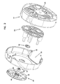
- a paper web material dispenser 10 that incorporates the concepts of the invention is illustrated in Figures 1-3.
- the illustrated dispenser 10 is a three roll toilet tissue dispenser.
- a first roll is accessible for dispensing tissue while the second and third rolls are generally inaccessible until the first roll is completely depleted or substantially depleted.
- the dispenser then permits access to the second roll so that it can dispense tissue.
- the dispenser then permits access to the third roll so that it can dispense tissue.
- completely depleted and substantially depleted as used in this patent application mean all or a sufficient amount of tissue has been removed from a roll at the dispensing position to allow transfer to the next roll.
- depleted will hereinafter be used, it being understood that this term encompasses both complete depletion of tissue as well as depletion to an extent that permits transfer to the next roll.
- dispenser 10 is described as a three roll toilet tissue dispenser, the concepts described herein can be used on tissue dispensers having a smaller, e.g. one, or larger, e.g. four, number of rolls, as well as on dispensers that dispense other types of paper web material, such as paper towel dispensers.
- the dispenser 10 comprises a housing formed by a front cover 12, and a rear housing 14 that together define a housing interior.
- the rear housing 14 is configured for attachment to a wall or other support surface.
- the front cover 12 is pivotally connected to the rear housing 14 for pivoting movement relative to the rear housing between a closed position, shown in Figure 3, and an open position (not shown).
- the front cover 12 is pivotable to the open position to provide access to the housing interior and the tissue rolls held therein, and to allow replenishment of the rolls.
- Pivotal attachment of the front cover 12 to the rear housing 14 is provided by pivots 16 (shown in Figures 1, 8 and 9) on the rear housing 14 and flanges 18 on the front cover 12 with holes that receive the pivots 16.
- pivots 16 shown in Figures 1, 8 and 9
- flanges 18 on the front cover 12 with holes that receive the pivots 16.
- a suitable locking mechanism 22 known to persons of skill in the art, is provided to maintain the cover at the closed position and deter access to the housing interior during use of the dispenser.
- the post 32 is sized to fit over the support post 24.
- the interior of the post 32 includes a boss 36 with a pin 38 that fits into a hole 40 formed in the end of the post 24.
- This construction rotatably supports the dispensing mechanism 28 on the support post 24 and the rear housing 14.
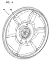
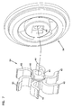
- the front side of the front cover 12 is recessed 42 and a user actuation mechanism in the form of an actuation disk 44 is rotatably disposed in the recess 42.
- the disk 44 has a stabilizing flange 46 extending from the rear thereof that, as best shown in Figure 3, engages the base of the recess 42 to stabilize rotation of the disk 44.
- the disk 44 includes a cylindrical drive boss 48 that surrounds a boss 50.
- the interior of the drive boss 48 is provided with teeth 52 that form part of a drive mechanism connecting the actuation disk 44 to the dispensing mechanism 28 so as to rotate the dispensing mechanism 28 upon rotation of the disk 44.
- Rotation of the disk 44 is facilitated by handles 45 formed on the front side of the disk.
- the drive mechanism also includes a torque limiting mechanism 54, a ratchet 56, and drive teeth 58 on the post 32.
- the torque limiting mechanism 54 is configured to automatically disconnect the dispensing mechanism 28 from the actuation disk 44 when the actuation disk is rotated with a torque that exceeds a predetermined limit, and which automatically reconnects the dispensing mechanism and the actuation disk when the torque on the actuation disk falls below the predetermined limit.
- the torque limiting mechanism 54 is in the form of a slip clutch mechanism that prevents rotation of the dispensing mechanism when the actuation disk is actuated with a force that exceeds the predetermined limit.
- the torque limiting mechanism 54 is seen to include a hub 60 with a plurality of arms 62 projecting outwardly therefrom.
- the illustrated embodiment utilizes six arms 62, although a larger or smaller number of arms could be used.
- the arms 62 which are preferably formed of a flexible, resilient plastic, for example nylon or acetal, are curved in the intended direction of rotation of the disk 44 (the rotation direction is indicated by an arrow in Figure 4).
- the hub 60 is able to fit within the boss 48, and the ends of the arms 62 are engaged with the teeth 52.
- the ends of the arms 62 will flex out of the teeth 52 when the torque on the disk 44 exceeds a predetermined limit.
- the arms 62 will automatically flex out of the teeth 52 at a torque limit of between approximately 50-60 in/lbs, which, in this disclosed embodiment, is roughly equivalent to 15 lbs of force applied to the handle 45.
- Americans with Disabilities Act (ADA) guidelines recommend that approximately 5 lbs of force applied to the handle 45 be sufficient to rotate the disk 44 when the dispenser is functioning properly.
- the dispensing mechanism 28 When the arms flex out of the teeth, the dispensing mechanism 28 is disconnected from the disk 44 whereby rotation of the disk 44 will no longer be transmitted to remaining portions of the drive mechanism so that the dispensing mechanism will not be rotated. However, when the torque falls below the predetermined limit, the arms 62 will automatically flex back into engagement with the teeth 52, thereby reconnecting the dispensing mechanism 28 and the disk 44 so that rotation of the disk results in rotation of the dispensing mechanism.
- the drive teeth 68 of the ratchet 56 are engaged with the drive teeth 58 formed at the end of the post 32.
- the drive teeth 58 like the drive teeth 68, each have a drive face 74 and sloped, non-driving faces 76 between the drive faces 74.
- the torque limiting mechanism 54 fits within the boss 48, with the arms 62 thereof engaged with the teeth 52.
- the ratchet 56 is supported within a boss 76 on the front cover 12, and the boss 50 extends through and beyond the torque limiting mechanism 54 and ratchet 56.
- a screw 78 is inserted into the boss 50 and tightens to the boss 50, but does not tighten to the torque limiting mechanism 54 or ratchet 56. Therefore, the disk 44, boss 50 and screw 78 will turn freely relative to the torque limiting mechanism 54 and ratchet 56 when torques above the predetermined limit are applied.
- the dispenser 10 is configured so that rotation of the disk 44 in one direction only can result in rotation of the dispensing mechanism 28.
- rotation of the disk 44 in a clockwise direction can result in rotation of the dispensing mechanism in a corresponding clockwise direction.
- Rotation of the disk 44 in a counterclockwise direction will not rotate the dispensing mechanism because the drive faces 70 of the drive teeth on the ratchet 56 and the drive faces 74 of the drive teeth 58 on the end of the post 32 will not engage due to the configuration of the drive teeth 58, 68.
- clockwise rotation of the disk 44 can result in rotation of the dispensing mechanism, because the drive faces 70 of the drive teeth on the ratchet 56 and the drive faces 74 of the drive teeth 58 on the end of the post 32 will engage.
- rotation of the dispensing mechanism will only occur if the torque on the disk 44 is below the predetermined limit. Malfunctions in the operation of the dispensing mechanism 28 can cause the torque to increase above the predetermined limit. For example, the dispensing mechanism could become jammed due to a mechanical malfunction or due to tissue paper. Alternatively, a tissue roll that is currently at the dispensing position may not be sufficiently depleted, as will be discussed further below, thereby preventing rotation of the dispensing mechanism.
- the flexible arms 62 of the torque limiting mechanism 54 will cause the disk 44 to rotate or slip relative to the torque limiting mechanism when the applied torque exceeds the predetermined limit. This prevents the excessive force from being applied to the remainder of the drive mechanism and to the dispensing mechanism, thereby avoiding potential damage to the dispenser.
- the mandrels 34a-c which are identical in construction, each project from the plate 30 in a direction that is generally parallel to the axis of rotation of the dispensing mechanism.
- Each mandrel 34a-c is designed to support a tissue roll during use, so the size of the mandrels should be chosen to permit the cores of the tissue rolls to fit over the mandrels and permit rotation of the core relative to the mandrel when tissue is being pulled from each roll.
- the mandrels are preferably designed for use with reduced core tissue rolls.
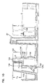
- Reduced core tissue rolls are rolls having cores comprised of first and second core sections 100, 102 (shown in Figure 10) that are spaced apart from each other to form a gap between facing ends thereof so that the total length of the core sections is less than the width of the tissue wound onto the core sections. Reduced core tissue rolls are described in U.S. Patents 6,648,267 and 6,491,251.
- Each mandrel 34a-c comprises a first mandrel section 104 fixed to the plate 30, a second mandrel section 106 extending from the first mandrel section 104, and a ledge 108.
- the first mandrel section 104 has a maximum radial dimension r 1 (i.e. a maximum dimension measured along the radial axis) that is greater than the maximum radial dimension r 2 of the second mandrel section 106.
- the difference in the sizes of the mandrel sections 104, 106 creates the ledge 108, whose radial dimension r 3 is equal to the difference between r 1 and r 2 .
- the ledges 108 face radially outwardly for a purpose to be described below.
- the core section 100 is received on the mandrel section 104 in a relatively close fitting relation.
- the core section 102 which is the same diameter as the core section 100, is received loosely on the mandrel section 106. This permits the core section 102 to be pushed inwardly toward the post 32, as shown in Figure 10, during rotation of the dispensing mechanism 28 to bring a new roll into the dispensing position upon depletion of a roll at the dispensing position.
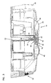
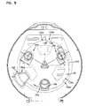
- a stop 110 is fixed to the back plate 26 of the rear housing 14.
- the stop 110 projects in the same general direction as the mandrels 34a-c, and includes a base portion 112 and a deflecting portion 114 that projects radially inwardly toward the post 32 into the rotation path of the mandrels 34a-c.
- the distance d 1 that the deflecting portion 114 projects into the rotation path is approximately equal to the radial dimension of the ledge 108.
- the mandrel section 106 has a maximum length, l 1 , measured along its axis of projection, and the deflecting portion 114 has a maximum height, h 1 , that is less than the maximum length of the second mandrel section 106.
- Figure 8 illustrates the mandrel 34a at the dispensing position (e.g. positioned directly above the dispensing opening 20), with a depleted roll of tissue on the mandrel so that only the core sections 100, 102 remain.
- the plate 30 is rotated in a clockwise direction in order to bring a new roll disposed on the mandrel 34c into the dispensing position
- the mandrel 34a approaches the stop 110.
- the core section 102 engages the deflecting portion 114, which pushes the core section 102 inwardly toward the post 32.
- the mandrel section 104 passes under the deflecting portion 114. In this manner, the mandrel 34a with the depleted roll thereon can pass by the stop 110 to bring the roll disposed on the mandrel 34c into the dispensing position.
- the stop 110 will prevent the new roll from being brought to the dispensing position until the roll on the mandrel 34a is sufficiently depleted to permit enough movement of the core section 102 inwardly toward the post 32 to permit the mandrel 34a to pass by the stop 110.
- the stop 110 will prevent such an action.
- the user faced with the stopping action of the stop 110, tries to force further rotation of the dispensing mechanism by rotating the actuation disk 44 even harder, damage could occur to the dispenser 10, for example the drive mechanism, portions of the dispensing mechanism 28, or the stop 110, if the applied torque is large enough.
- the torque limiting mechanism 54 will disconnect the driving force of the disk 44 from the remainder of the dispenser prior to the torque level reaching an amount at which damage to the dispenser can occur. As a result, damage to the dispenser is prevented.
- the stop 110 further comprises a detent spring 118 that includes a detent finger 120 engaged with the perimeter edge 122 of the plate 30, as best shown in Figures 8 and 10.
- the finger 120 is resiliently biased into engagement with the perimeter edge 122 in order to maintain contact with the edge 122 as the plate 30 rotates.
- the edge 122 is provided with a plurality of detents 124a, 124b, 124c that cooperate with the detent finger 120 to help retain the mandrels 34a-c at the dispensing position.
- Figures 8 and 10 illustrate the detent finger 120 within the detent 124a.
- Each detent 124a-c includes a front stop surface 126 and a ramp surface 128.
- the stop surface 126 engages with the finger 120 to prevent counterclockwise rotation of the plate 30.
- the ramp surface 128 allows the finger 120 to leave the detent when the plate 30 is rotated clockwise when bringing a new roll to the dispensing position.
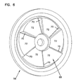
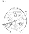
- the perimeter edge 122 of the plate 30 is non-circular.
- the shape of the edge 122 is such that it has three lobes 130a, 130b, 130c that have a radius greater than the radius of the edge 122 between the lobes 130a-c.
- the mandrels 34a-c are positioned adjacent the edge 122 at the smaller radiused portions of the plate 30 between the mandrels 34a-c, while the detents 124a-c are positioned at the lobes 130a-c, respectively.
- the shape of the edge 122 is such that the edge acts like a cam for the detent finger 120.
- the finger 120 rides on the smaller radiused portions of the edge 122. As the next mandrel gets closer to the dispensing position, the radius of the edge 122 increases and pushes on the finger 120 with increasing force. Eventually, the finger 120 snaps into place into the detent 124a-c to hold the mandrel at the dispensing position to dispense the new roll.
- each mandrel 34a-c has features designed to keep the core sections 100, 102 separated when tissue is depleted.
- each mandrel 34a-c includes a tab 140 formed thereon at the intersection of the mandrel sections 104, 106.
- the tab 140 projects radially inwardly.
- a sloped surface 142 extends between the mandrel section 106 and the tab 140. Further, as seen in Figure 10, there is a small difference x between the radially inwardmost surface of the mandrel section 106 and the radially inwardmost surface of the mandrel section 104.
- the core section 100 rides on the sloped surface 142 so that the core section 100 can clear the tab 140.
- the core sections 100, 102 will be arranged as shown in Figure 10, with the core section 100 below the tab 140 and the core section 102 above the tab 140.
- the tab 140 limits movement of the core section 100 toward the core section 102, while the sloped surface 142 and tab 140 prevent the core section 102 from dropping down toward the core section 100. The result is that the core sections 100, 102 are kept separated. By keeping the core sections separated, the stop 110 will function as intended.
Abstract
Description
Claims (26)
- A paper web material dispenser, comprising:a housing having a housing interior;a dispensing mechanism disposed within the housing interior and mounted for rotation about an axis, the dispensing mechanism configured to support at least one roll of paper web material thereon;a user actuation mechanism accessible from outside the housing, the user actuation mechanism being supported by the dispenser for movement relative to the housing;a drive mechanism connecting the actuation mechanism to the dispensing mechanism; anda slip clutch mechanism that is configured to prevent rotation of the dispensing mechanism when the actuation mechanism is actuated with a force that exceeds a predetermined limit.
- The dispenser of claim 1, wherein the actuation mechanism is a rotatable disk, and the slip clutch mechanism is configured to limit the torque that is applied to the dispensing mechanism when the disk is rotated.
- The dispenser of claim 2, wherein the slip clutch mechanism forms part of the drive mechanism.
- The dispenser of claim 2, wherein the slip clutch mechanism is rotatable with the disk about an axis that is coaxial to the rotation axis of the dispensing mechanism.
- A paper web material dispenser, comprising:a housing having a housing interior;a dispensing mechanism disposed within the housing interior and mounted for rotation about an axis, the dispensing mechanism configured to support at least one roll of paper web material thereon;a user actuation mechanism accessible from outside the housing, the user actuation mechanism being supported by the dispenser for movement relative to the housing;a drive mechanism connecting the actuation mechanism to the dispensing mechanism; anda torque limiting mechanism that is configured to automatically disconnect the dispensing mechanism from the actuation mechanism when the actuation mechanism is actuated with a torque that exceeds a predetermined limit and that is configured to automatically reconnect the dispensing mechanism and the actuation mechanism when the torque on the actuation mechanism falls below the predetermined limit.
- The dispenser of claim 5, wherein the actuation mechanism is a rotatable disk, and the torque limiting mechanism is configured to limit the torque that is applied to the dispensing mechanism when the disk is rotated.
- The dispenser of claim 6, wherein the torque limiting mechanism forms part of the drive mechanism.
- The dispenser of claim 6, wherein the torque limiting mechanism is rotatable with the disk about an axis that is coaxial to the rotation axis of the dispensing mechanism.
- A toilet tissue dispenser, comprising:a housing having a housing interior;a dispensing mechanism disposed within the housing interior and mounted for rotation about an axis, the dispensing mechanism configured to support at least one roll of toilet tissue thereon;a rotatable actuation disk supported by the dispenser on the outside of the housing for rotation relative to the housing; anda drive mechanism connecting the actuation disk to the dispensing mechanism, the drive mechanism includes a torque limiting mechanism that is configured to prevent rotation of the dispensing mechanism when a torque applied to the actuation disk exceeds a predetermined limit.
- The dispenser of claim 9, wherein the torque limiting mechanism is rotatable with the disk about an axis that is coaxial to the rotation axis of the dispensing mechanism.
- The dispenser of claim 9, wherein the dispensing mechanism is configured to support at least three rolls of toilet tissue.
- The dispenser of claim 9, wherein the dispensing mechanism comprises a plate, a central post connected to the plate and projecting therefrom generally parallel to the rotation axis, and at least three mandrels connected to the plate and projecting therefrom generally parallel to the central post, the mandrels being equally spaced from each other on the plate.
- The dispenser of claim 9, wherein the drive mechanism is configured to rotate the dispensing mechanism is a single direction about the rotation axis.
- The dispenser of claim 13, wherein the dispensing mechanism comprises drive teeth, and wherein the drive mechanism further comprises a ratchet having drive teeth engaged with the drive teeth of the dispensing mechanism.
- The dispenser of claim 14, wherein the torque limiting mechanism is in driving engagement with the ratchet, and the actuation disk is in driving engagement with the torque limiting mechanism.
- The dispenser of claim 15, wherein the actuation disk comprises a dial with a cylindrical boss having inner gear teeth, and the torque limiting mechanism comprises a hub with a plurality of outwardly projecting arms, wherein the hub is disposed within the boss and the arms are engaged with the inner gear teeth.
- The dispenser of claim 16, wherein the outwardly projecting arms are curved in a direction of rotation of the dispensing mechanism and are flexible, wherein the arms have sufficient flexibility so that the arms will flex out of engagement with the inner gear teeth when the torque applied to the actuation disk exceeds the predetermined limit.
- The dispenser of claim 12, wherein each mandrel comprises a first mandrel portion connected to the plate, and a second mandrel portion connected to the first mandrel portion, wherein the second mandrel portion has a reduced size compared to the first mandrel portion to define a ledge on the mandrel.
- The dispenser of claim 18, wherein the ledges face outwardly away from the rotation axis.
- The dispenser of claim 12, further comprising a stop fixed to the housing and configured to engage web material rolls disposed on the mandrels.
- A paper web material dispenser, comprising:a) a housing having a housing interior;b) a dispensing mechanism disposed within the housing interior and mounted for rotation about an axis, the dispensing mechanism includes:i) a plate; andii) a plurality of mandrels fixed to the plate and projecting therefrom in a direction generally parallel to the rotation axis of the dispensing mechanism, each mandrel is configured to support a roll of paper web material thereon, and each mandrel comprises a first mandrel section and a second mandrel section, the first mandrel section having a radial dimension that is greater than a radial dimension of the second mandrel section, and each mandrel includes a ledge having a radial dimension that is equal to the difference between the radial dimension of the first mandrel section and the radial dimension of the second mandrel section;c) a stop disposed within the housing interior, the stop includes a portion that projects radially into a rotation path of the mandrels, and where the radial distance that the stop projects into the rotation path is approximately equal to the radial dimension of the ledge.
- The dispenser of claim 21, wherein the second mandrel section has a maximum length measured along its axis of projection, and the portion of the stop that projects radially into the rotation path has a maximum height that is less than the maximum length of the second mandrel section.
- The dispenser of claim 21, wherein the ledges are positioned to face radially outwardly.
- The dispenser of claim 21, comprising three mandrels.
- The dispenser of claim 24, wherein the plate includes a non-circular perimeter edge having three lobes.
- The dispenser of claim 25, wherein the mandrels are positioned on the plate between the lobes.
Applications Claiming Priority (2)
| Application Number | Priority Date | Filing Date | Title |
|---|---|---|---|
| US769321 | 2004-01-30 | ||
| US10/769,321 US7014140B2 (en) | 2004-01-30 | 2004-01-30 | Three roll tissue dispenser |
Publications (3)
| Publication Number | Publication Date |
|---|---|
| EP1559356A2 true EP1559356A2 (en) | 2005-08-03 |
| EP1559356A3 EP1559356A3 (en) | 2006-08-02 |
| EP1559356B1 EP1559356B1 (en) | 2010-07-07 |
Family
ID=34654384
Family Applications (1)
| Application Number | Title | Priority Date | Filing Date |
|---|---|---|---|
| EP05250329A Not-in-force EP1559356B1 (en) | 2004-01-30 | 2005-01-24 | Three roll tissue dispenser |
Country Status (8)
| Country | Link |
|---|---|
| US (2) | US7014140B2 (en) |
| EP (1) | EP1559356B1 (en) |
| AT (1) | ATE472962T1 (en) |
| CA (1) | CA2495163C (en) |
| DE (1) | DE602005022133D1 (en) |
| DK (1) | DK1559356T3 (en) |
| ES (1) | ES2349705T3 (en) |
| MX (1) | MXPA05001177A (en) |
Cited By (4)
| Publication number | Priority date | Publication date | Assignee | Title |
|---|---|---|---|---|
| CN109788880A (en) * | 2016-08-19 | 2019-05-21 | 阿奇通股份公司 | Sheet dispensers with spring-loaded operation trigger member |
| EP3695765A3 (en) * | 2019-02-13 | 2020-11-11 | San Jamar, Inc. | Carousel style dispenser |
| US10850938B2 (en) | 2017-10-09 | 2020-12-01 | Gpcp Ip Holdings Llc | Mechanical sheet product dispenser |
| US10952569B2 (en) | 2017-05-10 | 2021-03-23 | Gpcp Ip Holdings Llc | Premature replacement prevention or deterrence for multiple roll sheet product dispensers |
Families Citing this family (38)
| Publication number | Priority date | Publication date | Assignee | Title |
|---|---|---|---|---|
| US7014140B2 (en) * | 2004-01-30 | 2006-03-21 | Bay West Paper Corporation | Three roll tissue dispenser |
| US7461810B2 (en) * | 2004-11-12 | 2008-12-09 | Georgia-Pacifiic Consumer Products Lp | Tissue roll dispenser |
| EP1933684A1 (en) * | 2006-06-06 | 2008-06-25 | Buckeye Technologies Inc. | Versatile core size tissue dispenser |
| US7841556B2 (en) * | 2006-11-21 | 2010-11-30 | Wausau Paper Towel & Tissue, Llc | System and method for dispensing paper towel |
| WO2009075950A1 (en) * | 2007-10-22 | 2009-06-18 | The Colman Group, Inc. | Web material dispenser |
| US20110233254A1 (en) * | 2008-12-01 | 2011-09-29 | Sca Hygiene Products Ab | Dispenser |
| US8041008B2 (en) | 2009-01-29 | 2011-10-18 | The Invention Science Fund I, Llc | Diagnostic delivery service |
| US8130904B2 (en) | 2009-01-29 | 2012-03-06 | The Invention Science Fund I, Llc | Diagnostic delivery service |
| WO2010096408A1 (en) * | 2009-02-17 | 2010-08-26 | Collins Design Inc. | Reset linkage assembly for blocking shield of multi-roll paper dispenser |
| US8356767B2 (en) * | 2009-12-15 | 2013-01-22 | Sca Tissue North America Llc | Dispenser for multiple rolls of web material with automatic roll transfer, and method of loading same |
| US8479957B2 (en) * | 2010-06-25 | 2013-07-09 | Gotohti.Com Inc. | Combined toilet paper and fluid dispenser |
| US9138110B2 (en) | 2011-07-25 | 2015-09-22 | Wausau Paper Towel & Tissue, Llc | Tissue dispenser, method for dispensing tissue, and tissue dispenser insert |
| US9126802B2 (en) | 2012-04-30 | 2015-09-08 | Adc Telecommunications, Inc. | Payout spool with automatic cable disconnect/reconnect |
| WO2013165899A1 (en) | 2012-04-30 | 2013-11-07 | Adc Telecommunications, Inc. | Cable payout cassette with single layer cable storage area |
| EP2845281A4 (en) * | 2012-04-30 | 2015-12-23 | Adc Telecommunications Inc | Cable storage spool with center feed |
| US9722407B2 (en) | 2012-04-30 | 2017-08-01 | Commscope Technologies Llc | Guided cable storage assembly with switchbacks |
| US9027872B2 (en) * | 2012-07-26 | 2015-05-12 | Rosemary Flood | Free standing dispenser apparatus for rolled sheet material |
| CN102755130B (en) * | 2012-08-03 | 2014-06-04 | 金红叶纸业集团有限公司 | Storing and taking-out device for life paper |
| US10123666B2 (en) | 2012-11-30 | 2018-11-13 | Gpcp Ip Holdings Llc | System and method for reducing waste using a sheet product dispenser |
| WO2014093192A1 (en) * | 2012-12-11 | 2014-06-19 | Georgia-Pacific Consumer Products Lp | Dispenser having more than one output drive condition |
| MX2016003217A (en) | 2013-09-13 | 2016-09-29 | Wausau Paper Towel & Tissue Llc | Tissue dispenser and method for dispensing tissue. |
| DE202016102766U1 (en) | 2016-04-26 | 2016-06-30 | Kawa Abdul Sharif | Toilet paper dispenser |
| CA179934S (en) | 2018-02-23 | 2020-03-05 | Cascades Canada Ulc | Dispenser |
| CA179935S (en) | 2018-02-23 | 2020-03-05 | Cascades Canada Ulc | Dispenser |
| CA181663S (en) | 2018-05-29 | 2021-03-08 | Cascades Canada Ulc | Paper dispenser |
| CA181664S (en) | 2018-05-29 | 2021-03-08 | Cascades Canada Ulc | Paper dispenser |
| CA181854S (en) | 2018-06-07 | 2020-03-05 | Cascades Canada Ulc | Paper dispenser |
| US11529029B2 (en) * | 2018-06-12 | 2022-12-20 | Essity Hygiene And Health Aktiebolag | Support spindle assembly for a roll |
| WO2020123491A1 (en) | 2018-12-12 | 2020-06-18 | Osborne Charles Agnew Jr | Dispensing assembly for selectively dispensing a plurality of supplies of rolled sheet material |
| USD899806S1 (en) | 2019-03-28 | 2020-10-27 | San Jamar, Inc. | Roll towel dispenser lockout |
| USD1009613S1 (en) * | 2019-03-28 | 2024-01-02 | San Jamar, Inc | Roll towel dispenser lockout |
| US11083348B2 (en) | 2019-03-28 | 2021-08-10 | San Jamar, Inc. | Rolled web material dispenser material lockout systems |
| US11072513B2 (en) | 2019-03-28 | 2021-07-27 | San Jamar, Inc. | Rolled web material dispenser material lockout systems |
| US11071417B2 (en) | 2019-03-28 | 2021-07-27 | San Jamar, Inc. | Rolled web material dispenser material lockout systems |
| US11224316B2 (en) | 2019-03-28 | 2022-01-18 | San Jamar, Inc. | Rolled web material dispenser material lockout systems |
| US11406231B2 (en) | 2019-04-26 | 2022-08-09 | Dispensing Dynamics International, Inc. | Automatic roll transfer dispenser |
| CN110288771B (en) * | 2019-06-24 | 2021-09-10 | 北控滨南康健(重庆)环境工程有限公司 | Intelligent toilet paper supply system and method for public toilet |
| US11447355B2 (en) | 2020-06-03 | 2022-09-20 | San Jamar, Inc. | Rolled web material feed assembly |
Citations (1)
| Publication number | Priority date | Publication date | Assignee | Title |
|---|---|---|---|---|
| US6491251B1 (en) | 2000-03-09 | 2002-12-10 | Bay West Paper Corporation | Double core tissue roll, dispenser and method |
Family Cites Families (41)
| Publication number | Priority date | Publication date | Assignee | Title |
|---|---|---|---|---|
| US3126234A (en) * | 1964-03-24 | Rolls of paper toweling and dispensers therefor | ||
| US1108855A (en) * | 1914-01-12 | 1914-08-25 | Scovill Manufacturing Co | Reel-fixture. |
| US1716812A (en) * | 1924-06-07 | 1929-06-11 | R Hoe And Co Inc | Roll changer |
| US2299626A (en) * | 1939-08-16 | 1942-10-20 | William V Hunt | Paper roll and mounting therefor |
| US2726823A (en) * | 1952-11-20 | 1955-12-13 | American Linen Supply Co | Supply roll mounting means for dispensing cabinets |
| US2905405A (en) * | 1955-10-10 | 1959-09-22 | Crown Zellerbach Corp | Supporting and coupling means for supply rolls |
| US3085762A (en) * | 1959-02-05 | 1963-04-16 | Berkley Machine Co | Roll changing apparatus |
| US3084006A (en) * | 1960-06-13 | 1963-04-02 | Crown Zellerbach Corp | Two-roll paper dispenser |
| US3214014A (en) * | 1963-04-23 | 1965-10-26 | Towlsaver Inc | Roll of strip material having a separable core structure |
| US3211504A (en) * | 1963-11-21 | 1965-10-12 | Ind Res And Dev Corp | Dispenser for rolls of paper |
| US3294329A (en) * | 1964-01-27 | 1966-12-27 | Towlsaver Inc | Method and apparatus for dispensing strip material |
| US3381909A (en) * | 1966-01-03 | 1968-05-07 | Towlsaver Inc | Apparatus for sequentially dispensing rolls of strip material |
| US3387902A (en) * | 1967-01-03 | 1968-06-11 | Towlsaver Inc | Dispenser for sequentially dispensing rolls of tissue and the like |
| US3438589A (en) * | 1967-03-08 | 1969-04-15 | Georgia Pacific Corp | Flexible sheet material rolls having internal supporting means adapted to fall out of a dispenser automatically |
| US3433355A (en) * | 1967-06-30 | 1969-03-18 | Minnesota Mining & Mfg | Tape roll and method of making the roll |
| US3437388A (en) * | 1967-09-14 | 1969-04-08 | Georgia Pacific Corp | Dispenser for rolls of flexible sheet material |
| US3650487A (en) * | 1970-03-06 | 1972-03-21 | Steiner American Corp | Two-roll tissue dispenser |
| US4008956A (en) * | 1975-03-24 | 1977-02-22 | Xerox Corporation | Document handling system for pre-collation copying |
| CH599777A5 (en) * | 1976-12-17 | 1978-05-31 | Moelnlycke Gmbh | |
| US4179078A (en) * | 1978-10-10 | 1979-12-18 | Mansfield Donna J | Toilet paper dispenser |
| US4223964A (en) * | 1979-03-19 | 1980-09-23 | Kilgore Bobby R | Tissue holder |
| GB2104871B (en) * | 1981-08-03 | 1985-01-23 | Paperplan Hygiene Limited | A paper dispenser |
| US4522346A (en) * | 1983-12-06 | 1985-06-11 | Georgia-Pacific Corporation | Method and apparatus for dispensing web material from split core rolls |
| US4557426A (en) * | 1984-06-28 | 1985-12-10 | Siciliano Stephen J | Dispenser for toilet paper and the like |
| NL8602194A (en) | 1986-08-28 | 1988-03-16 | Edet Nederland | Multiple roll toilet paper holder - has holder casing enclosing roll support shaft mounted on rotary carrier |
| JPS6396063U (en) * | 1986-12-15 | 1988-06-21 | ||
| JPH02163247A (en) * | 1988-12-14 | 1990-06-22 | Mitsubishi Electric Corp | Facsimile device |
| GB9013034D0 (en) | 1990-06-12 | 1990-08-01 | Crisp & Wilson Ltd | Improved dispenser for disposable sheet material supplied in roll form |
| US5236141A (en) * | 1992-03-25 | 1993-08-17 | Kewin Daniel D | Tubular core assemblies for rolls of paper or other sheet material |
| US5310129A (en) * | 1993-05-17 | 1994-05-10 | James River Paper Company, Inc. | System for sequentially dispensing web material from a plurality of rolls |
| US5833169A (en) * | 1993-09-02 | 1998-11-10 | G. H. Wood & Wyant Inc. | Large roll bathroom tissue dispenser with stub roll holder |
| US5449127A (en) * | 1993-12-14 | 1995-09-12 | Davis; Robert T. | Dispenser for rolls of sheet material |
| US5605001A (en) * | 1994-03-10 | 1997-02-25 | Derk; Laura J. | Ornamental scroll device |
| US5454500A (en) * | 1994-07-05 | 1995-10-03 | Cheng-feng Chen | Toilet-paper holder |
| CA2171491C (en) * | 1995-03-10 | 2005-09-27 | John Michael Conner | Dispensing apparatus |
| US5749538A (en) * | 1995-08-02 | 1998-05-12 | Kimberly-Clark Corp. | Gravity-operated dispensing apparatus |
| US5615845A (en) * | 1996-04-03 | 1997-04-01 | Kewin; Daniel D. | Tubular core assembilies for rolls of paper or other sheet material |
| US6302352B1 (en) * | 2000-02-07 | 2001-10-16 | Albert H. Applegate | Warning tape dispenser and carrier |
| US6386479B1 (en) * | 2001-06-22 | 2002-05-14 | Kimberly-Clark Worldwide, Inc. | Coreless roll carriage unit adapter for dispensers |
| US6616087B1 (en) * | 2002-07-26 | 2003-09-09 | Shyue Jinn Chern | Rotary tape dispenser |
| US7014140B2 (en) * | 2004-01-30 | 2006-03-21 | Bay West Paper Corporation | Three roll tissue dispenser |
-
2004
- 2004-01-30 US US10/769,321 patent/US7014140B2/en active Active
-
2005
- 2005-01-24 DK DK05250329.9T patent/DK1559356T3/en active
- 2005-01-24 DE DE602005022133T patent/DE602005022133D1/en active Active
- 2005-01-24 AT AT05250329T patent/ATE472962T1/en active
- 2005-01-24 ES ES05250329T patent/ES2349705T3/en active Active
- 2005-01-24 EP EP05250329A patent/EP1559356B1/en not_active Not-in-force
- 2005-01-27 CA CA002495163A patent/CA2495163C/en active Active
- 2005-01-28 MX MXPA05001177A patent/MXPA05001177A/en active IP Right Grant
-
2006
- 2006-01-10 US US11/329,805 patent/US7114676B2/en not_active Expired - Lifetime
Patent Citations (2)
| Publication number | Priority date | Publication date | Assignee | Title |
|---|---|---|---|---|
| US6491251B1 (en) | 2000-03-09 | 2002-12-10 | Bay West Paper Corporation | Double core tissue roll, dispenser and method |
| US6648267B2 (en) | 2000-03-09 | 2003-11-18 | Bay West Paper Corporation | Double core tissue roll, dispenser and method |
Cited By (7)
| Publication number | Priority date | Publication date | Assignee | Title |
|---|---|---|---|---|
| CN109788880A (en) * | 2016-08-19 | 2019-05-21 | 阿奇通股份公司 | Sheet dispensers with spring-loaded operation trigger member |
| US10952569B2 (en) | 2017-05-10 | 2021-03-23 | Gpcp Ip Holdings Llc | Premature replacement prevention or deterrence for multiple roll sheet product dispensers |
| US11766154B2 (en) | 2017-05-10 | 2023-09-26 | Gpcp Ip Holdings Llc | Premature replacement prevention or deterrence for multiple roll sheet product dispensers |
| US10850938B2 (en) | 2017-10-09 | 2020-12-01 | Gpcp Ip Holdings Llc | Mechanical sheet product dispenser |
| US11780699B2 (en) | 2017-10-09 | 2023-10-10 | Gpcp Ip Holdings Llc | Sheet product dispenser with spring assembly |
| EP3695765A3 (en) * | 2019-02-13 | 2020-11-11 | San Jamar, Inc. | Carousel style dispenser |
| US11122942B2 (en) | 2019-02-13 | 2021-09-21 | San Jamar, Inc. | Carousel style dispenser |
Also Published As
| Publication number | Publication date |
|---|---|
| CA2495163A1 (en) | 2005-07-30 |
| DK1559356T3 (en) | 2010-10-11 |
| US20050167544A1 (en) | 2005-08-04 |
| CA2495163C (en) | 2008-11-04 |
| DE602005022133D1 (en) | 2010-08-19 |
| US7014140B2 (en) | 2006-03-21 |
| MXPA05001177A (en) | 2006-04-27 |
| US7114676B2 (en) | 2006-10-03 |
| ES2349705T3 (en) | 2011-01-10 |
| ATE472962T1 (en) | 2010-07-15 |
| US20060108467A1 (en) | 2006-05-25 |
| EP1559356A3 (en) | 2006-08-02 |
| EP1559356B1 (en) | 2010-07-07 |
Similar Documents
| Publication | Publication Date | Title |
|---|---|---|
| CA2495163C (en) | Three roll tissue dispenser | |
| CA1132950A (en) | Dual roll towel dispenser | |
| US20170188760A1 (en) | Dispenser | |
| US6354533B1 (en) | Web transfer mechanism for flexible sheet dispenser | |
| KR101159872B1 (en) | Dispenser for multiple rolls of sheet material | |
| EP1011406B1 (en) | Adapter and dispenser for coreless rolls of products | |
| US5288032A (en) | Dispenser for flexible sheet material | |
| CA2090776C (en) | Dispenser for multiple rolls of sheet material | |
| RU2546420C2 (en) | Proportioner for multiple material reels with their automatic displacement and method of proportioner loading | |
| US6491251B1 (en) | Double core tissue roll, dispenser and method | |
| EP0647423B1 (en) | Apparatus for dispensing web material from a roll | |
| US5456420A (en) | Rolled tissue dispenser | |
| EP1933684A1 (en) | Versatile core size tissue dispenser | |
| US6439502B1 (en) | Dispenser for coreless rolls of products | |
| EP1571956A1 (en) | Solid rolls dispenser | |
| CA2561424C (en) | Dispenser for rolled sheet material | |
| US7066423B2 (en) | Solid rolls dispenser | |
| US11083348B2 (en) | Rolled web material dispenser material lockout systems | |
| US20230157491A1 (en) | Dispensing Device with Restricted Towel Dispenser | |
| US20220192441A1 (en) | Paper roll dispenser | |
| CA2392332A1 (en) | Breakaway core arms for towel cabinet | |
| JPH03158990A (en) | Hopper type medal discharging device |
Legal Events
| Date | Code | Title | Description |
|---|---|---|---|
| PUAI | Public reference made under article 153(3) epc to a published international application that has entered the european phase |
Free format text: ORIGINAL CODE: 0009012 |
|
| AK | Designated contracting states |
Kind code of ref document: A2 Designated state(s): AT BE BG CH CY CZ DE DK EE ES FI FR GB GR HU IE IS IT LI LT LU MC NL PL PT RO SE SI SK TR |
|
| AX | Request for extension of the european patent |
Extension state: AL BA HR LV MK YU |
|
| PUAL | Search report despatched |
Free format text: ORIGINAL CODE: 0009013 |
|
| AK | Designated contracting states |
Kind code of ref document: A3 Designated state(s): AT BE BG CH CY CZ DE DK EE ES FI FR GB GR HU IE IS IT LI LT LU MC NL PL PT RO SE SI SK TR |
|
| AX | Request for extension of the european patent |
Extension state: AL BA HR LV MK YU |
|
| 17P | Request for examination filed |
Effective date: 20070202 |
|
| AKX | Designation fees paid |
Designated state(s): AT BE BG CH CY CZ DE DK EE ES FI FR GB GR HU IE IS IT LI LT LU MC NL PL PT RO SE SI SK TR |
|
| RAP1 | Party data changed (applicant data changed or rights of an application transferred) |
Owner name: WAUSAU PAPER TOWEL & TISSUE, LLC |
|
| 17Q | First examination report despatched |
Effective date: 20090610 |
|
| GRAP | Despatch of communication of intention to grant a patent |
Free format text: ORIGINAL CODE: EPIDOSNIGR1 |
|
| GRAC | Information related to communication of intention to grant a patent modified |
Free format text: ORIGINAL CODE: EPIDOSCIGR1 |
|
| GRAS | Grant fee paid |
Free format text: ORIGINAL CODE: EPIDOSNIGR3 |
|
| GRAA | (expected) grant |
Free format text: ORIGINAL CODE: 0009210 |
|
| AK | Designated contracting states |
Kind code of ref document: B1 Designated state(s): AT BE BG CH CY CZ DE DK EE ES FI FR GB GR HU IE IS IT LI LT LU MC NL PL PT RO SE SI SK TR |
|
| REG | Reference to a national code |
Ref country code: GB Ref legal event code: FG4D |
|
| REG | Reference to a national code |
Ref country code: CH Ref legal event code: EP |
|
| REG | Reference to a national code |
Ref country code: IE Ref legal event code: FG4D |
|
| REF | Corresponds to: |
Ref document number: 602005022133 Country of ref document: DE Date of ref document: 20100819 Kind code of ref document: P |
|
| REG | Reference to a national code |
Ref country code: SE Ref legal event code: TRGR |
|
| REG | Reference to a national code |
Ref country code: DK Ref legal event code: T3 |
|
| REG | Reference to a national code |
Ref country code: NL Ref legal event code: T3 |
|
| PG25 | Lapsed in a contracting state [announced via postgrant information from national office to epo] |
Ref country code: SI Free format text: LAPSE BECAUSE OF FAILURE TO SUBMIT A TRANSLATION OF THE DESCRIPTION OR TO PAY THE FEE WITHIN THE PRESCRIBED TIME-LIMIT Effective date: 20100707 |
|
| LTIE | Lt: invalidation of european patent or patent extension |
Effective date: 20100707 |
|
| REG | Reference to a national code |
Ref country code: ES Ref legal event code: FG2A Effective date: 20101227 |
|
| PG25 | Lapsed in a contracting state [announced via postgrant information from national office to epo] |
Ref country code: LT Free format text: LAPSE BECAUSE OF FAILURE TO SUBMIT A TRANSLATION OF THE DESCRIPTION OR TO PAY THE FEE WITHIN THE PRESCRIBED TIME-LIMIT Effective date: 20100707 |
|
| PG25 | Lapsed in a contracting state [announced via postgrant information from national office to epo] |
Ref country code: BG Free format text: LAPSE BECAUSE OF FAILURE TO SUBMIT A TRANSLATION OF THE DESCRIPTION OR TO PAY THE FEE WITHIN THE PRESCRIBED TIME-LIMIT Effective date: 20101007 Ref country code: CY Free format text: LAPSE BECAUSE OF FAILURE TO SUBMIT A TRANSLATION OF THE DESCRIPTION OR TO PAY THE FEE WITHIN THE PRESCRIBED TIME-LIMIT Effective date: 20100707 Ref country code: IS Free format text: LAPSE BECAUSE OF FAILURE TO SUBMIT A TRANSLATION OF THE DESCRIPTION OR TO PAY THE FEE WITHIN THE PRESCRIBED TIME-LIMIT Effective date: 20101107 Ref country code: PL Free format text: LAPSE BECAUSE OF FAILURE TO SUBMIT A TRANSLATION OF THE DESCRIPTION OR TO PAY THE FEE WITHIN THE PRESCRIBED TIME-LIMIT Effective date: 20100707 Ref country code: PT Free format text: LAPSE BECAUSE OF FAILURE TO SUBMIT A TRANSLATION OF THE DESCRIPTION OR TO PAY THE FEE WITHIN THE PRESCRIBED TIME-LIMIT Effective date: 20101108 |
|
| PG25 | Lapsed in a contracting state [announced via postgrant information from national office to epo] |
Ref country code: GR Free format text: LAPSE BECAUSE OF FAILURE TO SUBMIT A TRANSLATION OF THE DESCRIPTION OR TO PAY THE FEE WITHIN THE PRESCRIBED TIME-LIMIT Effective date: 20101008 |
|
| PLBE | No opposition filed within time limit |
Free format text: ORIGINAL CODE: 0009261 |
|
| STAA | Information on the status of an ep patent application or granted ep patent |
Free format text: STATUS: NO OPPOSITION FILED WITHIN TIME LIMIT |
|
| PG25 | Lapsed in a contracting state [announced via postgrant information from national office to epo] |
Ref country code: CZ Free format text: LAPSE BECAUSE OF FAILURE TO SUBMIT A TRANSLATION OF THE DESCRIPTION OR TO PAY THE FEE WITHIN THE PRESCRIBED TIME-LIMIT Effective date: 20100707 Ref country code: EE Free format text: LAPSE BECAUSE OF FAILURE TO SUBMIT A TRANSLATION OF THE DESCRIPTION OR TO PAY THE FEE WITHIN THE PRESCRIBED TIME-LIMIT Effective date: 20100707 Ref country code: SK Free format text: LAPSE BECAUSE OF FAILURE TO SUBMIT A TRANSLATION OF THE DESCRIPTION OR TO PAY THE FEE WITHIN THE PRESCRIBED TIME-LIMIT Effective date: 20100707 Ref country code: RO Free format text: LAPSE BECAUSE OF FAILURE TO SUBMIT A TRANSLATION OF THE DESCRIPTION OR TO PAY THE FEE WITHIN THE PRESCRIBED TIME-LIMIT Effective date: 20100707 |
|
| 26N | No opposition filed |
Effective date: 20110408 |
|
| REG | Reference to a national code |
Ref country code: DE Ref legal event code: R097 Ref document number: 602005022133 Country of ref document: DE Effective date: 20110408 |
|
| PG25 | Lapsed in a contracting state [announced via postgrant information from national office to epo] |
Ref country code: MC Free format text: LAPSE BECAUSE OF NON-PAYMENT OF DUE FEES Effective date: 20110131 |
|
| REG | Reference to a national code |
Ref country code: CH Ref legal event code: PL |
|
| PG25 | Lapsed in a contracting state [announced via postgrant information from national office to epo] |
Ref country code: LI Free format text: LAPSE BECAUSE OF NON-PAYMENT OF DUE FEES Effective date: 20110131 Ref country code: CH Free format text: LAPSE BECAUSE OF NON-PAYMENT OF DUE FEES Effective date: 20110131 |
|
| PG25 | Lapsed in a contracting state [announced via postgrant information from national office to epo] |
Ref country code: LU Free format text: LAPSE BECAUSE OF NON-PAYMENT OF DUE FEES Effective date: 20110124 |
|
| PG25 | Lapsed in a contracting state [announced via postgrant information from national office to epo] |
Ref country code: TR Free format text: LAPSE BECAUSE OF FAILURE TO SUBMIT A TRANSLATION OF THE DESCRIPTION OR TO PAY THE FEE WITHIN THE PRESCRIBED TIME-LIMIT Effective date: 20100707 |
|
| PG25 | Lapsed in a contracting state [announced via postgrant information from national office to epo] |
Ref country code: HU Free format text: LAPSE BECAUSE OF FAILURE TO SUBMIT A TRANSLATION OF THE DESCRIPTION OR TO PAY THE FEE WITHIN THE PRESCRIBED TIME-LIMIT Effective date: 20100707 |
|
| REG | Reference to a national code |
Ref country code: FR Ref legal event code: PLFP Year of fee payment: 12 |
|
| REG | Reference to a national code |
Ref country code: FR Ref legal event code: PLFP Year of fee payment: 13 |
|
| PGFP | Annual fee paid to national office [announced via postgrant information from national office to epo] |
Ref country code: GB Payment date: 20161228 Year of fee payment: 13 Ref country code: DK Payment date: 20161229 Year of fee payment: 13 Ref country code: IE Payment date: 20161229 Year of fee payment: 13 Ref country code: FI Payment date: 20161229 Year of fee payment: 13 |
|
| PGFP | Annual fee paid to national office [announced via postgrant information from national office to epo] |
Ref country code: NL Payment date: 20170109 Year of fee payment: 13 |
|
| PGFP | Annual fee paid to national office [announced via postgrant information from national office to epo] |
Ref country code: FR Payment date: 20170103 Year of fee payment: 13 Ref country code: SE Payment date: 20170109 Year of fee payment: 13 Ref country code: DE Payment date: 20170131 Year of fee payment: 13 |
|
| PGFP | Annual fee paid to national office [announced via postgrant information from national office to epo] |
Ref country code: AT Payment date: 20161229 Year of fee payment: 13 Ref country code: BE Payment date: 20170116 Year of fee payment: 13 |
|
| PGFP | Annual fee paid to national office [announced via postgrant information from national office to epo] |
Ref country code: ES Payment date: 20170119 Year of fee payment: 13 Ref country code: IT Payment date: 20170117 Year of fee payment: 13 |
|
| REG | Reference to a national code |
Ref country code: DE Ref legal event code: R119 Ref document number: 602005022133 Country of ref document: DE |
|
| REG | Reference to a national code |
Ref country code: DK Ref legal event code: EBP Effective date: 20180131 |
|
| REG | Reference to a national code |
Ref country code: SE Ref legal event code: EUG |
|
| REG | Reference to a national code |
Ref country code: NL Ref legal event code: MM Effective date: 20180201 |
|
| REG | Reference to a national code |
Ref country code: AT Ref legal event code: MM01 Ref document number: 472962 Country of ref document: AT Kind code of ref document: T Effective date: 20180124 |
|
| GBPC | Gb: european patent ceased through non-payment of renewal fee |
Effective date: 20180124 |
|
| PG25 | Lapsed in a contracting state [announced via postgrant information from national office to epo] |
Ref country code: SE Free format text: LAPSE BECAUSE OF NON-PAYMENT OF DUE FEES Effective date: 20180125 Ref country code: FR Free format text: LAPSE BECAUSE OF NON-PAYMENT OF DUE FEES Effective date: 20180131 Ref country code: FI Free format text: LAPSE BECAUSE OF NON-PAYMENT OF DUE FEES Effective date: 20180124 Ref country code: DE Free format text: LAPSE BECAUSE OF NON-PAYMENT OF DUE FEES Effective date: 20180801 |
|
| REG | Reference to a national code |
Ref country code: IE Ref legal event code: MM4A |
|
| REG | Reference to a national code |
Ref country code: FR Ref legal event code: ST Effective date: 20180928 |
|
| REG | Reference to a national code |
Ref country code: BE Ref legal event code: MM Effective date: 20180131 |
|
| PG25 | Lapsed in a contracting state [announced via postgrant information from national office to epo] |
Ref country code: BE Free format text: LAPSE BECAUSE OF NON-PAYMENT OF DUE FEES Effective date: 20180131 Ref country code: NL Free format text: LAPSE BECAUSE OF NON-PAYMENT OF DUE FEES Effective date: 20180201 Ref country code: GB Free format text: LAPSE BECAUSE OF NON-PAYMENT OF DUE FEES Effective date: 20180124 Ref country code: AT Free format text: LAPSE BECAUSE OF NON-PAYMENT OF DUE FEES Effective date: 20180124 |
|
| PG25 | Lapsed in a contracting state [announced via postgrant information from national office to epo] |
Ref country code: IE Free format text: LAPSE BECAUSE OF NON-PAYMENT OF DUE FEES Effective date: 20180124 Ref country code: DK Free format text: LAPSE BECAUSE OF NON-PAYMENT OF DUE FEES Effective date: 20180131 |
|
| PG25 | Lapsed in a contracting state [announced via postgrant information from national office to epo] |
Ref country code: IT Free format text: LAPSE BECAUSE OF NON-PAYMENT OF DUE FEES Effective date: 20180124 |
|
| REG | Reference to a national code |
Ref country code: ES Ref legal event code: FD2A Effective date: 20190731 |
|
| PG25 | Lapsed in a contracting state [announced via postgrant information from national office to epo] |
Ref country code: ES Free format text: LAPSE BECAUSE OF NON-PAYMENT OF DUE FEES Effective date: 20180125 |