EP1560040A2 - Vehicle backward movement assist device - Google Patents
Vehicle backward movement assist device Download PDFInfo
- Publication number
- EP1560040A2 EP1560040A2 EP05001084A EP05001084A EP1560040A2 EP 1560040 A2 EP1560040 A2 EP 1560040A2 EP 05001084 A EP05001084 A EP 05001084A EP 05001084 A EP05001084 A EP 05001084A EP 1560040 A2 EP1560040 A2 EP 1560040A2
- Authority
- EP
- European Patent Office
- Prior art keywords
- distance
- tone
- acoustic
- trailer
- ramp
- Prior art date
- Legal status (The legal status is an assumption and is not a legal conclusion. Google has not performed a legal analysis and makes no representation as to the accuracy of the status listed.)
- Withdrawn
Links
Images
Classifications
-
- B—PERFORMING OPERATIONS; TRANSPORTING
- B60—VEHICLES IN GENERAL
- B60Q—ARRANGEMENT OF SIGNALLING OR LIGHTING DEVICES, THE MOUNTING OR SUPPORTING THEREOF OR CIRCUITS THEREFOR, FOR VEHICLES IN GENERAL
- B60Q9/00—Arrangement or adaptation of signal devices not provided for in one of main groups B60Q1/00 - B60Q7/00, e.g. haptic signalling
- B60Q9/002—Arrangement or adaptation of signal devices not provided for in one of main groups B60Q1/00 - B60Q7/00, e.g. haptic signalling for parking purposes, e.g. for warning the driver that his vehicle has contacted or is about to contact an obstacle
- B60Q9/007—Arrangement or adaptation of signal devices not provided for in one of main groups B60Q1/00 - B60Q7/00, e.g. haptic signalling for parking purposes, e.g. for warning the driver that his vehicle has contacted or is about to contact an obstacle providing information about the distance to an obstacle, e.g. varying sound
-
- B—PERFORMING OPERATIONS; TRANSPORTING
- B60—VEHICLES IN GENERAL
- B60Q—ARRANGEMENT OF SIGNALLING OR LIGHTING DEVICES, THE MOUNTING OR SUPPORTING THEREOF OR CIRCUITS THEREFOR, FOR VEHICLES IN GENERAL
- B60Q9/00—Arrangement or adaptation of signal devices not provided for in one of main groups B60Q1/00 - B60Q7/00, e.g. haptic signalling
- B60Q9/002—Arrangement or adaptation of signal devices not provided for in one of main groups B60Q1/00 - B60Q7/00, e.g. haptic signalling for parking purposes, e.g. for warning the driver that his vehicle has contacted or is about to contact an obstacle
- B60Q9/004—Arrangement or adaptation of signal devices not provided for in one of main groups B60Q1/00 - B60Q7/00, e.g. haptic signalling for parking purposes, e.g. for warning the driver that his vehicle has contacted or is about to contact an obstacle using wave sensors
- B60Q9/006—Arrangement or adaptation of signal devices not provided for in one of main groups B60Q1/00 - B60Q7/00, e.g. haptic signalling for parking purposes, e.g. for warning the driver that his vehicle has contacted or is about to contact an obstacle using wave sensors using a distance sensor
-
- G—PHYSICS
- G08—SIGNALLING
- G08G—TRAFFIC CONTROL SYSTEMS
- G08G1/00—Traffic control systems for road vehicles
- G08G1/16—Anti-collision systems
- G08G1/165—Anti-collision systems for passive traffic, e.g. including static obstacles, trees
Definitions
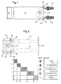
- the vehicle shown schematically in Figure 1 consists of a trailer 10, which is controlled with its rear 12 backwards to a ramp of a tractor 16 shall be.
- a simple uniform Facility 14 to facilitate, the tail 12 in the usual way with sensors 20th equipped to send their waves 22 toward a ramp and the Wave reflex received.
- the unit 14 which is self-sufficient and not in communication with the cab 16
- the sensors 20 include an evaluation circuit 26 connected to these and two signal transmitters 28,30, which are also exclusively at the rear 12 of the Auflegers 10 are located. It is an acoustic signal generator 28 and a or more optical signal transmitter 30. In the present example, two optical Signal transmitter 30 located. These are not additional Lights, but it will be the already existing outline lights or tail lights used.
- the driver also only needs to turn on the parking light to the optical signalers to light up.
- the reverse gear activated the reverse driving light or a sensor monitoring the rotation of the rear wheels the unit 14 with the evaluation circuit 26.
- the waves 22 meet at a Ramp 24 and the reflected waves are received again.
- the term will be determined in a computing unit of the evaluation circuit 26, in the distance size converted and converted into output signals. These are not for Cab delivered but at the stern 12 visually and acoustically with qualitative Differences displayed. This is done acoustically on the one hand on the side the rear 12 mounted speaker 28, which is located on the driver's side and unmistakable beeps.
- Side tail lights 30 (white forward, red red) subjected to the distance-adequate signals and made to flash.
- Fig. 2 From the lower part of Fig. 2 is an example of the quality of the signals in dependence from the distance between the stern 12 and ramp 24 in stages I to V out. At a distance of more than 3 m there is no signal, neither acoustically nor optically. Between 2 and 3 m there is a 3 Hz tone and / or a sound interval of one 1/3 second and visually a glow with about a quarter of the full luminosity. Between 1 to 2 m distance there is a 5 Hz tone and / or a sound interval of one 1/5 second and visually a glow with about half full brightness. Between a distance of 0.5 to 1 m takes place an 8 Hz tone and / or an audio interval of a 1/8 second and optically glowing with about a quarter of the full brightness. Below a distance of half a meter, there is one Continuous tone and a full light intensity as continuous lights. Of course The distances and levels chosen here by way of example may deviate from Example can be selected. You can choose finer steps or larger distances
- the system is designed for truck trailers or semi - trailers, autonomous and independently at the stern works. It's simple, inexpensive and can be done anytime be subsequently attached to the truck trailer or trailer. Nevertheless, increased the new system provides safety for the vehicle and the objects behind the vehicle. There are fewer damages and repairs. There is no Intervention in the engine control and brake system and the driver's freedom of action is not limited.
- the low-cost rig comes with two adjustable ultrasonic sensors 20 off. If there are loud noises at a maneuvering point at night are undesirable, the acoustic display can also be switched off. This can even without affecting the autonomy of the plant, from the cab over the electric lights are switched by the reverse gear twice behind each other is inserted, what at the rear on the tail lights can be recognized and tapped.
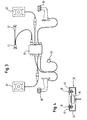
- Figure 3 illustrates the modular system for attachment to the rear of a Trailer or trailer. It is a kit of the two sensors, 20 of the evaluation circuit in a junction box 26 and the acoustic signal generator 28th specified with a cable connection set, which only in the power supply of Rear lights need to be clamped in via connections 32. The anyway mostly available rear side marker lights are not directly, but via the terminals 32 and the evaluation circuit 26 and the cable set reconnected.
- This simple and cab-independent facility is a simple, inexpensive and reliable ramp approach help.
Abstract
Description
Die vorliegende Erfindung bezieht sich auf eine Einrichtung um das Rückwärtsanfahren insbesondere mit einem Auflegerfahrzeug an eine Laderampe zu erleichtern. Im modernen Lieferverkehr spielt jede Zeitersparnis eine große Rolle. Lieferfahrzeuge sollen schnell und sicher an eine Laderampe zum Beladen oder Entladen rückwärts herangefahren werden. Hierbei werden auch immer häufiger Fahrzeuge mit Aufleger eingesetzt, weil man mit einer Zugmaschine mehrere Aufleger betreiben kann. Wenn eine Zugmaschine beispielsweise einen Aufleger an eine Laderampe heranrangiert hat, um ihn beladen zu lassen, kann mit derselben Zugmaschine ein bereits beladener Aufleger weggefahren werden.The present invention relates to a device for reversing especially with a trailer vehicle to facilitate a loading dock. In modern delivery traffic, every time saving plays a major role. delivery vehicles should quickly and safely to a loading dock for loading or unloading be moved backwards. Here are also more and more vehicles used with trailer, because with a tractor several trailer can operate. For example, when a tractor attaches a trailer to a trailer Loading ramp has been arranged to let him load, can with the same tractor an already loaded trailer be driven away.
Nun ist es schon bei schlecht zugänglichen Rampen bereits schwierig, einen normalen Lastwagen rückwärts an eine Rampe herzulenken. Umso schwieriger lässt sich dieses Manöver bei einem Gelenkzug schnell ausführen. Seit längerem werden als Anfahrhilfe für dieses Manöver Rückwärtsfahrsensoren eingesetzt. Diese messen beim Annähern an eine Laderampe den jeweils verbleibenden Abstand vom Heck des Fahrzeugs zur Rampe und zeigen diesen Abstand mit optischen oder akustischen Signalen im Fahrerhaus an. Bei Auflegern muss dann, wenn die Zugmaschine abgekoppelt wird, die Signalverbindung zum Fahrerhaus gelöst werden. Außerdem sind die bekannten Anfahrhilfen aus anderen Gründen teuer und aufwendig. Aus der DE 198 31 262 A1 ( entsprechend EP 0972679 ) ist eine Einrichtung zur Unterstützung des Fahrers eines Fahrzeuges beim Rückwärtsfahren bekannt. Hierbei wird ein zu einem Hindernis charakterisierendes Abstandssignal ausgewertet, wobei in Abhängigkeit von diesem Signal die Geschwindigkeit des Fahrzeuges automatisch beeinflusst wird. Diese Automatik wirkt auf die Geschwindigkeitsregelung und das Bremssystem des Fahrzeugs, ohne dass der Fahrer einzugreifen braucht. Das führt zu einer Kompliziertheit und Verteuerung der Anfahrhilfe. Außerdem besteht ein erhebliches Anpassungsproblem beim Wechseln des Anhängers oder Auflegers, da Motorleistung- und Einstellung des Bremssystem bei jedem Wechsel adjustiert werden müssen, um sicherzustellen, dass bei einer gewechselten Kombination von Zugmaschine und Hänger oder Aufleger die Automatik zuverlässig eingestellt ist.Now it is already difficult with difficult to access ramps, a normal Truck backwards to a ramp. The more difficult it is Perform this maneuver quickly on a articulated train. For a long time used as traction help for this maneuver reverse driving sensors. These When approaching a loading ramp, measure the remaining distance from the rear of the vehicle to the ramp and show this distance with optical or acoustic signals in the cab. With Auflegern must then, if the Tractor is disconnected, the signal connection to the cab are released. In addition, the known traction aids are expensive for other reasons consuming. From DE 198 31 262 A1 (corresponding to EP 0972679) is a device to assist the driver of a vehicle when reversing known. This becomes a distance signal characterizing an obstacle evaluated, depending on this signal, the speed of Vehicle is automatically influenced. This automatic acts on the speed control and the braking system of the vehicle without the driver intervening needs. This leads to a complexity and increase in the price of traction. In addition, there is a significant adjustment problem in changing the Trailer or Auflegers, because engine performance and adjustment of the brake system at Every change must be adjusted to ensure that when a change Combination of tractor and trailer or trailer the automatic is set reliably.
Es besteht daher die Aufgabe, eine Anfahrhilfe verfügbar zu machen, die einfach ist und wenig Aufwand erfordert. Diese Aufgabe wird erfindungsgemäß durch eine Einrichtung mit am Heck angebrachten Sensoren gelöst, deren Wellen und Wellenreflexion in einer Schaltung über Auswertung der Laufzeit den Abstand zur Rampe bestimmen und in optische und/oder akustische Signale umwandeln. Diese optischen und akustischen Signale werden am Heck des Fahrzeugzuges abgegeben, unabhängig von Einrichtungen im Fahrerhaus, an der Motorsteuerung oder der Bremsanlage nur in Abhängigkeit von dem sich ändernden Abstand vom Heck zur Rampe oder einem anderen Hindernis. Der Fahrer selbst bleibt selbst derjenige, der lenkt, den Motor beeinflusst oder bremst. Er erhält vom Heck her beim gewohnten Blick nach hinten lediglich akustische und optische Hilfesignale. Diese Hilfe wirkt unabhängig von der Konstellation einer Zugmaschine zu einem beliebigen Hänger oder Aufleger, der mit dem einfachen und autarken Hilfesystem ausgerüstet ist. Ein Wechsel bedingt keine neuen Einstellungen. Das Besondere besteht mithin in der Einfachheit, damit einer kostengünstigen Einrichtung, die auch leicht nachgerüstet werden kann und in ihrer Flexibilität. Das resultiert daraus, dass eine Auswertschaltung und die akustischen und optischen Signalgeber eine vom Fahrerhaus unabhängige Einheit am Heck des Fahrzeugs bilden.It is therefore the task of making available a traction help that is easy is and requires little effort. This object is achieved by a Device with rear-mounted sensors solved, their waves and wave reflection in a circuit via evaluation of the running time the distance to the ramp determine and convert it into optical and / or acoustic signals. This optical and acoustic signals are emitted at the rear of the vehicle platoon, irrespective of the cab equipment, the engine control or the Brake system only as a function of the changing distance from the rear to Ramp or another obstacle. The driver himself remains the one which steers, affects the engine or brakes. He receives from the rear at the usual Look behind only acoustic and optical help signals. This help works regardless of the constellation of a tractor to any Hanger or trailer equipped with the simple and self-sufficient help system is. A change does not require new settings. The special thing is Consequently, in simplicity, thus a cost-effective device that is also lightweight can be retrofitted and in their flexibility. This results from the fact that a Evaluation circuit and the acoustic and optical signal transmitter one from the cab to form an independent unit at the rear of the vehicle.
Weitere Einzelheiten, Vorteile und Merkmale der Erfindung ergeben sich aus der folgenden Beschreibung eines in der Zeichnung schematisch dargestellten Ausführungsbeispiels, sowie aus den anschließenden Ansprüchen.Further details, advantages and features of the invention will become apparent from the following description of an embodiment schematically illustrated in the drawing, as well as from the subsequent claims.
Es zeigen:
Das in Figur 1 schematisch dargestellte Fahrzeug besteht aus einem Aufleger 10,
der mit seinem Heck 12 rückwärts an eine Rampe von einer Zugmaschine 16 gesteuert
werden soll. Um dieses Anfahrmanöver mit einer einfachen einheitlichen
Einrichtung 14 zu erleichtern, ist das Heck 12 in üblicher Weise mit Sensoren 20
ausgestattet die ihre Wellen 22 in Richtung auf eine Rampe aussenden und den
Wellenreflex empfangen.The vehicle shown schematically in Figure 1 consists of a
Die eigentliche Funktionsweise geht aus Figur 2 hervor.The actual functioning is shown in FIG.
Zur Einheit 14, die autark und nicht mit dem Fahrerhaus 16 in Verbindung steht,
gehören außer den Sensoren 20 eine mit diesen verbundene Auswertschaltung 26
und zwei Signalgeber 28,30, die sich ebenfalls ausschließlich am Heck 12 des Auflegers
10 befinden. Es handelt sich um einen akustischen Signalgeber 28 und einen
oder mehrere optische Signalgeber 30. Im vorliegenden Beispiel sind zwei optische
Signalgeber 30 eingezeichnet. Es handelt sich dabei nicht um zusätzlich vorgesehen
Leuchten, sondern es werden die ohnehin vorhandenen Umrißleuchten
oder Heckbegrenzungsleuchten benutzt.To the
Der akustische Signalgeber befindet sich seitlich am Heck 12 auf der Fahrerseite und kann daher vom Fahrer gut wahrgenommen werden. Zudem wird jeder Fahrer beim Rückwärtsfahren zumeist bei offnem Fenster entweder direkt oder über den Spiegel das Heck 12 seines Fahrzeugs im Auge behalten, schon um bei dieser Fahrweise nicht andere Gegenstände oder gar Personen zu gefährden.The acoustic signal transmitter is located laterally on the rear 12 on the driver's side and therefore can be well perceived by the driver. In addition, every driver will when reversing mostly with open window either directly or via the Mirror the rear 12 of his vehicle in mind, even at this Driving not to endanger other objects or even persons.
Der Fahrer braucht auch nur das Standlicht einzuschalten, um die optischen Signalgeber
leuchten zu lassen. Sobald der Rückwartsgang eingelegt wird, aktiviert
das Rückwartsfahrlicht oder ein die Drehung der Hinterräder überwachender Sensor
die Einheit 14 mit der Auswertschaltung 26. Die Wellen 22 treffen auf eine
Rampe 24 und die reflektierten Wellen werden wieder empfangen. Die Laufzeit wird
in einer Recheneinheit der Auswertschaltung 26 bestimmt, in die Abstandgröße
umgerechnet und in Ausgabesignale umgewandelt. Diese werden aber nicht zum
Fahrerhaus geliefert, sondern am Heck 12 optisch und akustisch mit qualitativen
Unterschieden angezeigt. Dies erfolgt einerseits akustisch über den an der Seite
des Hecks 12 angebrachten Lautsprecher 28, der auf der Fahrerseite befindet und
unüberhörbar Pieptöne aussendet. Außerdem werden die zumeist ohnehin vorhandenen
seitlichen Heckbegrenzungsleuchten 30 (nach vorn weiß, nach hinten rot)
mit den abstandsadäquaten Signalen beaufschlagt und zum Blinken gebracht.The driver also only needs to turn on the parking light to the optical signalers
to light up. Once the reverse gear is engaged, activated
the reverse driving light or a sensor monitoring the rotation of the rear wheels
the
Aus dem unteren Teil der Fig. 2 geht beispielhaft die Qualität der Signale in Abhängigkeit
vom Abstand zwischen Heck 12 und Rampe 24 in Stufen I bis V hervor.
Beim Abstand von mehr als 3 m erfolgt noch kein Signal, weder akustisch noch optisch.
Zwischen 2 und 3 m erfolgt ein 3 Hz-Ton und/oder ein Tonintervall von einer
1/3 Sekunde und optisch ein Leuchten mit etwa ein Viertel der vollen Leuchtstärke.
Zwischen 1 bis 2 m Abstand erfolgt ein 5 Hz-Ton und/oder ein Tonintervall von einer
1/5 Sekunde und optisch ein Leuchten mit etwa der halben vollen Leuchtstärke.
Zwischen einem Abstand von 0,5 bis 1 m erfolgt ein 8 Hz-Ton und/oder ein Tonintervall
von einer 1/8 Sekunde und optisch ein Leuchten mit etwa ein dreiviertel der
vollen Leuchtstärke. Unterhalb eines Abstands von einem halben Meter gibt es einen
Dauerton und eine volle Lichtstärke als Dauerleuchten. Selbstverständlich
können die hier beispielhaft gewählten Abstände und Stufen auch abweichend vom
Beispiel gewählt werden. Es können feinere Stufen oder größere Abstände gewählt
werden.From the lower part of Fig. 2 is an example of the quality of the signals in dependence
from the distance between the
Wichtig ist, dass das System für LKW - Anhänger oder Aufleger, autonom und
selbstständig am Heck funktioniert. Es ist einfach, kostengünstig und kann jederzeit
nachträglich am LKW - Anhänger oder Aufleger angebracht werden. Dennoch erhöht
das neue System die Sicherheit für das Fahrzeug und die Gegenstände hinter
dem Fahrzeug. Es gibt weniger Schadensfälle und Reparaturen. Es erfolgt kein
Eingriff in die Motorsteuerung und Bremsanlage und die Handlungsfreiheit des Fahrers
ist nicht eingeschränkt. Die preiswerte Anlage kommt mit zwei justierbaren Ultraschallsensoren
20 aus. Wenn nachts an einem Rangierpunkt laute Geräusche
unerwünscht sind, lässt sich die akustische Anzeige auch abschalten. Dies kann
sogar, ohne die Autonomie der Anlage zu beieinträchtigen, vom Fahrerhaus über
die elektrische Beleuchtung umgeschaltet werden, indem der Rückwärtsgang
zweimal kurz hinter einander eingelegt wird, was am Heck über die Heckleuchten
erkannt und abgegriffen werden kann. Importantly, the system is designed for truck trailers or semi - trailers, autonomous and
independently at the stern works. It's simple, inexpensive and can be done anytime
be subsequently attached to the truck trailer or trailer. Nevertheless, increased
the new system provides safety for the vehicle and the objects behind
the vehicle. There are fewer damages and repairs. There is no
Intervention in the engine control and brake system and the driver's freedom of action
is not limited. The low-cost rig comes with two adjustable
Die Figur 3 verdeutlicht das Baukastensystem für die Anbringung am Heck eines
Aufleger oder Anhängers. Es ist ein Bausatz aus den zwei Sensoren, 20 der Auswertschaltung
in einem Anschlusskasten 26 und dem akustischen Signalgeber 28
mit einem Kabelverbindungssatz vorgegeben, der nur in die Stromversorgung der
Heckleuchten über Anschlüsse 32 eingespleist zu werden braucht. Die ohnehin
zumeist vorhanden hinteren Seitenbegrenzungsleuchten werden nicht direkt, sondern
über die Anschlüsse 32 und die Auswertschaltung 26 und dem Kabelsatz
wieder angeschlossen.Figure 3 illustrates the modular system for attachment to the rear of a
Trailer or trailer. It is a kit of the two sensors, 20 of the evaluation circuit
in a
Um einen Ultraschallsensor 36 in seinem Gehäuse 34 (Figur 4) richtig auszurichten
oder nachzujustieren ist eine Mehrpunktjustierung aus jeweils Schraube 38 und
Feder 40 vorhanden. Um die Justierung nur Fachleuten zu überlassen sind die
Schrauben 38 vorteilhafterweise nicht mit einem gewöhnlichen Schraubendreher
zu verstellen, sondern nur mit einem zu Bausatz gehörenden Schlüssel zu drehen,
der in ein entsprechendes Schloss im versenkten Kopf der Schraube 38 korrespondiert.To properly align an
Diese einfache und vom Fahrerhaus unabhängige Einrichtung ist eine einfache, preisgünstige und zuverlässige Rampenanfahrhilfe.This simple and cab-independent facility is a simple, inexpensive and reliable ramp approach help.
Claims (8)
Applications Claiming Priority (2)
| Application Number | Priority Date | Filing Date | Title |
|---|---|---|---|
| DE202004001473U DE202004001473U1 (en) | 2004-01-30 | 2004-01-30 | Ramp |
| DE202004001473U | 2004-01-30 |
Publications (2)
| Publication Number | Publication Date |
|---|---|
| EP1560040A2 true EP1560040A2 (en) | 2005-08-03 |
| EP1560040A3 EP1560040A3 (en) | 2005-08-17 |
Family
ID=32603358
Family Applications (1)
| Application Number | Title | Priority Date | Filing Date |
|---|---|---|---|
| EP05001084A Withdrawn EP1560040A3 (en) | 2004-01-30 | 2005-01-20 | Vehicle backward movement assist device |
Country Status (2)
| Country | Link |
|---|---|
| EP (1) | EP1560040A3 (en) |
| DE (1) | DE202004001473U1 (en) |
Cited By (1)
| Publication number | Priority date | Publication date | Assignee | Title |
|---|---|---|---|---|
| GB2424984A (en) * | 2005-04-06 | 2006-10-11 | Lee Bosanko | Reversing system for a vehicle housed in an under run bar |
Families Citing this family (1)
| Publication number | Priority date | Publication date | Assignee | Title |
|---|---|---|---|---|
| ITTO20080419A1 (en) * | 2008-05-30 | 2009-11-30 | System Truck S R L | RIDER ASSISTANCE SYSTEM DURING A MANEUVER OF APPROACHING A TRUCK TO A BANQUET |
Citations (6)
| Publication number | Priority date | Publication date | Assignee | Title |
|---|---|---|---|---|
| EP0381016A1 (en) * | 1989-02-01 | 1990-08-08 | Hohe Kg | External rear view mirror for a motor vehicle |
| EP0575814A1 (en) * | 1992-06-09 | 1993-12-29 | CENTRO RICERCHE FIAT Società Consortile per Azioni | Microwave distance sensor for parking vehicles |
| US6072391A (en) * | 1995-06-12 | 2000-06-06 | Toyoda Gosei Co., Ltd. | Information indicator for vehicle |
| US6326887B1 (en) * | 1998-10-13 | 2001-12-04 | Robert Bosch Gmbh | Vehicle parking aid system |
| US6380883B1 (en) * | 1998-02-23 | 2002-04-30 | Amerigon | High performance vehicle radar system |
| US20020180597A1 (en) * | 2001-05-31 | 2002-12-05 | Flick Kenneth E. | Back-up warning system in a license plate holder and related method |
-
2004
- 2004-01-30 DE DE202004001473U patent/DE202004001473U1/en not_active Expired - Lifetime
-
2005
- 2005-01-20 EP EP05001084A patent/EP1560040A3/en not_active Withdrawn
Patent Citations (6)
| Publication number | Priority date | Publication date | Assignee | Title |
|---|---|---|---|---|
| EP0381016A1 (en) * | 1989-02-01 | 1990-08-08 | Hohe Kg | External rear view mirror for a motor vehicle |
| EP0575814A1 (en) * | 1992-06-09 | 1993-12-29 | CENTRO RICERCHE FIAT Società Consortile per Azioni | Microwave distance sensor for parking vehicles |
| US6072391A (en) * | 1995-06-12 | 2000-06-06 | Toyoda Gosei Co., Ltd. | Information indicator for vehicle |
| US6380883B1 (en) * | 1998-02-23 | 2002-04-30 | Amerigon | High performance vehicle radar system |
| US6326887B1 (en) * | 1998-10-13 | 2001-12-04 | Robert Bosch Gmbh | Vehicle parking aid system |
| US20020180597A1 (en) * | 2001-05-31 | 2002-12-05 | Flick Kenneth E. | Back-up warning system in a license plate holder and related method |
Cited By (1)
| Publication number | Priority date | Publication date | Assignee | Title |
|---|---|---|---|---|
| GB2424984A (en) * | 2005-04-06 | 2006-10-11 | Lee Bosanko | Reversing system for a vehicle housed in an under run bar |
Also Published As
| Publication number | Publication date |
|---|---|
| EP1560040A3 (en) | 2005-08-17 |
| DE202004001473U1 (en) | 2004-06-24 |
Similar Documents
| Publication | Publication Date | Title |
|---|---|---|
| EP1044120B1 (en) | Warning device for an automobile | |
| DE4425419C1 (en) | Short-range ultrasonic distance warning system in a motor vehicle, especially as a parking aid | |
| DE102012024930A1 (en) | Vehicle with distance monitoring device | |
| DE102012017532A1 (en) | Method of operating a trailer or a truck with the system | |
| DE10341128A1 (en) | Device and method for detecting a current distance of a motor vehicle from an obstacle | |
| EP0993990A2 (en) | Parking-aid system | |
| DE19725656A1 (en) | Assisting method for safe overtaking in road traffic for vehicle | |
| CH680690A5 (en) | ||
| WO2006029725A1 (en) | Device for anticipating and avoiding collisions | |
| DE102016201813B3 (en) | Signaling the distance to obstacles in a remote controlled maneuvering assistance system | |
| EP2355996A1 (en) | Number plate holder | |
| WO2015055273A1 (en) | Vehicle and method for illuminating a region rearward of a vehicle | |
| DE10035124B4 (en) | Electronic distance warning system | |
| EP1560040A2 (en) | Vehicle backward movement assist device | |
| DE102011115378A1 (en) | Device for the safe approach of a water / faeces vehicle to an aircraft | |
| DE102018102398A1 (en) | Method for assisting a driver of a vehicle, in particular a utility vehicle | |
| DE4233624A1 (en) | Parking aid for large vehicles - comprises distance warning device with optical sensor system and electronic circuit controlling min. distance from vehicle rear to object | |
| DE3027493A1 (en) | Vehicle obstruction proximity detector and alarm - uses inductive transducers fore and aft and threshold alarm circuit | |
| DE19952892B4 (en) | Vehicle with electrically operated brake | |
| EP2742499B1 (en) | Rear area monitoring device for a vehicle, electronic control unit and vehicle having a rear area monitoring device | |
| DE19543457C1 (en) | Overtaking aid for commercial road vehicle | |
| DE102013008648A1 (en) | Method for automatically activating a distance warning system of a motor vehicle and distance warning system | |
| DE102010001370A1 (en) | Method for measuring the distance between an object and a motor vehicle | |
| DE102016005883B4 (en) | Method for controlling a back-up warning device of a vehicle | |
| DE10360137A1 (en) | Rangierhilfevorrichtung and method for determining an obstacle in a maneuvering |
Legal Events
| Date | Code | Title | Description |
|---|---|---|---|
| PUAI | Public reference made under article 153(3) epc to a published international application that has entered the european phase |
Free format text: ORIGINAL CODE: 0009012 |
|
| PUAL | Search report despatched |
Free format text: ORIGINAL CODE: 0009013 |
|
| AK | Designated contracting states |
Kind code of ref document: A2 Designated state(s): AT BE BG CH CY CZ DE DK EE ES FI FR GB GR HU IE IS IT LI LT LU MC NL PL PT RO SE SI SK TR |
|
| AX | Request for extension of the european patent |
Extension state: AL BA HR LV MK YU |
|
| AK | Designated contracting states |
Kind code of ref document: A3 Designated state(s): AT BE BG CH CY CZ DE DK EE ES FI FR GB GR HU IE IS IT LI LT LU MC NL PL PT RO SE SI SK TR |
|
| AX | Request for extension of the european patent |
Extension state: AL BA HR LV MK YU |
|
| RIC1 | Information provided on ipc code assigned before grant |
Ipc: 7B 60Q 1/48 B Ipc: 7G 01S 13/93 A |
|
| 17P | Request for examination filed |
Effective date: 20051213 |
|
| AKX | Designation fees paid |
Designated state(s): AT BE BG CH CY CZ DE DK EE ES FI FR GB GR HU IE IS IT LI LT LU MC NL PL PT RO SE SI SK TR |
|
| STAA | Information on the status of an ep patent application or granted ep patent |
Free format text: STATUS: THE APPLICATION IS DEEMED TO BE WITHDRAWN |
|
| 18D | Application deemed to be withdrawn |
Effective date: 20060418 |