EP1563810A1 - Dispositif chirurgical d'implantation d'une prothèse totale de hanche - Google Patents
Dispositif chirurgical d'implantation d'une prothèse totale de hanche Download PDFInfo
- Publication number
- EP1563810A1 EP1563810A1 EP05356029A EP05356029A EP1563810A1 EP 1563810 A1 EP1563810 A1 EP 1563810A1 EP 05356029 A EP05356029 A EP 05356029A EP 05356029 A EP05356029 A EP 05356029A EP 1563810 A1 EP1563810 A1 EP 1563810A1
- Authority
- EP
- European Patent Office
- Prior art keywords
- prosthesis
- femoral
- prosthetic
- cone
- implantation
- Prior art date
- Legal status (The legal status is an assumption and is not a legal conclusion. Google has not performed a legal analysis and makes no representation as to the accuracy of the status listed.)
- Granted
Links
Images


Classifications
-
- A—HUMAN NECESSITIES
- A61—MEDICAL OR VETERINARY SCIENCE; HYGIENE
- A61B—DIAGNOSIS; SURGERY; IDENTIFICATION
- A61B34/00—Computer-aided surgery; Manipulators or robots specially adapted for use in surgery
- A61B34/20—Surgical navigation systems; Devices for tracking or guiding surgical instruments, e.g. for frameless stereotaxis
-
- A—HUMAN NECESSITIES
- A61—MEDICAL OR VETERINARY SCIENCE; HYGIENE
- A61F—FILTERS IMPLANTABLE INTO BLOOD VESSELS; PROSTHESES; DEVICES PROVIDING PATENCY TO, OR PREVENTING COLLAPSING OF, TUBULAR STRUCTURES OF THE BODY, e.g. STENTS; ORTHOPAEDIC, NURSING OR CONTRACEPTIVE DEVICES; FOMENTATION; TREATMENT OR PROTECTION OF EYES OR EARS; BANDAGES, DRESSINGS OR ABSORBENT PADS; FIRST-AID KITS
- A61F2/00—Filters implantable into blood vessels; Prostheses, i.e. artificial substitutes or replacements for parts of the body; Appliances for connecting them with the body; Devices providing patency to, or preventing collapsing of, tubular structures of the body, e.g. stents
- A61F2/02—Prostheses implantable into the body
- A61F2/30—Joints
- A61F2/46—Special tools or methods for implanting or extracting artificial joints, accessories, bone grafts or substitutes, or particular adaptations therefor
- A61F2/4657—Measuring instruments used for implanting artificial joints
-
- A—HUMAN NECESSITIES
- A61—MEDICAL OR VETERINARY SCIENCE; HYGIENE
- A61F—FILTERS IMPLANTABLE INTO BLOOD VESSELS; PROSTHESES; DEVICES PROVIDING PATENCY TO, OR PREVENTING COLLAPSING OF, TUBULAR STRUCTURES OF THE BODY, e.g. STENTS; ORTHOPAEDIC, NURSING OR CONTRACEPTIVE DEVICES; FOMENTATION; TREATMENT OR PROTECTION OF EYES OR EARS; BANDAGES, DRESSINGS OR ABSORBENT PADS; FIRST-AID KITS
- A61F2/00—Filters implantable into blood vessels; Prostheses, i.e. artificial substitutes or replacements for parts of the body; Appliances for connecting them with the body; Devices providing patency to, or preventing collapsing of, tubular structures of the body, e.g. stents
- A61F2/02—Prostheses implantable into the body
- A61F2/30—Joints
- A61F2/46—Special tools or methods for implanting or extracting artificial joints, accessories, bone grafts or substitutes, or particular adaptations therefor
- A61F2/4684—Trial or dummy prostheses
-
- G—PHYSICS
- G06—COMPUTING; CALCULATING OR COUNTING
- G06T—IMAGE DATA PROCESSING OR GENERATION, IN GENERAL
- G06T7/00—Image analysis
- G06T7/70—Determining position or orientation of objects or cameras
- G06T7/73—Determining position or orientation of objects or cameras using feature-based methods
-
- A—HUMAN NECESSITIES
- A61—MEDICAL OR VETERINARY SCIENCE; HYGIENE
- A61B—DIAGNOSIS; SURGERY; IDENTIFICATION
- A61B34/00—Computer-aided surgery; Manipulators or robots specially adapted for use in surgery
- A61B34/10—Computer-aided planning, simulation or modelling of surgical operations
- A61B2034/101—Computer-aided simulation of surgical operations
- A61B2034/102—Modelling of surgical devices, implants or prosthesis
-
- A—HUMAN NECESSITIES
- A61—MEDICAL OR VETERINARY SCIENCE; HYGIENE
- A61B—DIAGNOSIS; SURGERY; IDENTIFICATION
- A61B34/00—Computer-aided surgery; Manipulators or robots specially adapted for use in surgery
- A61B34/10—Computer-aided planning, simulation or modelling of surgical operations
- A61B2034/101—Computer-aided simulation of surgical operations
- A61B2034/105—Modelling of the patient, e.g. for ligaments or bones
-
- A—HUMAN NECESSITIES
- A61—MEDICAL OR VETERINARY SCIENCE; HYGIENE
- A61B—DIAGNOSIS; SURGERY; IDENTIFICATION
- A61B34/00—Computer-aided surgery; Manipulators or robots specially adapted for use in surgery
- A61B34/20—Surgical navigation systems; Devices for tracking or guiding surgical instruments, e.g. for frameless stereotaxis
- A61B2034/2046—Tracking techniques
- A61B2034/2055—Optical tracking systems
-
- A—HUMAN NECESSITIES
- A61—MEDICAL OR VETERINARY SCIENCE; HYGIENE
- A61B—DIAGNOSIS; SURGERY; IDENTIFICATION
- A61B34/00—Computer-aided surgery; Manipulators or robots specially adapted for use in surgery
- A61B34/20—Surgical navigation systems; Devices for tracking or guiding surgical instruments, e.g. for frameless stereotaxis
- A61B2034/2072—Reference field transducer attached to an instrument or patient
-
- A—HUMAN NECESSITIES
- A61—MEDICAL OR VETERINARY SCIENCE; HYGIENE
- A61B—DIAGNOSIS; SURGERY; IDENTIFICATION
- A61B34/00—Computer-aided surgery; Manipulators or robots specially adapted for use in surgery
- A61B34/10—Computer-aided planning, simulation or modelling of surgical operations
-
- A—HUMAN NECESSITIES
- A61—MEDICAL OR VETERINARY SCIENCE; HYGIENE
- A61F—FILTERS IMPLANTABLE INTO BLOOD VESSELS; PROSTHESES; DEVICES PROVIDING PATENCY TO, OR PREVENTING COLLAPSING OF, TUBULAR STRUCTURES OF THE BODY, e.g. STENTS; ORTHOPAEDIC, NURSING OR CONTRACEPTIVE DEVICES; FOMENTATION; TREATMENT OR PROTECTION OF EYES OR EARS; BANDAGES, DRESSINGS OR ABSORBENT PADS; FIRST-AID KITS
- A61F2/00—Filters implantable into blood vessels; Prostheses, i.e. artificial substitutes or replacements for parts of the body; Appliances for connecting them with the body; Devices providing patency to, or preventing collapsing of, tubular structures of the body, e.g. stents
- A61F2/02—Prostheses implantable into the body
- A61F2/30—Joints
- A61F2/32—Joints for the hip
- A61F2/34—Acetabular cups
-
- A—HUMAN NECESSITIES
- A61—MEDICAL OR VETERINARY SCIENCE; HYGIENE
- A61F—FILTERS IMPLANTABLE INTO BLOOD VESSELS; PROSTHESES; DEVICES PROVIDING PATENCY TO, OR PREVENTING COLLAPSING OF, TUBULAR STRUCTURES OF THE BODY, e.g. STENTS; ORTHOPAEDIC, NURSING OR CONTRACEPTIVE DEVICES; FOMENTATION; TREATMENT OR PROTECTION OF EYES OR EARS; BANDAGES, DRESSINGS OR ABSORBENT PADS; FIRST-AID KITS
- A61F2/00—Filters implantable into blood vessels; Prostheses, i.e. artificial substitutes or replacements for parts of the body; Appliances for connecting them with the body; Devices providing patency to, or preventing collapsing of, tubular structures of the body, e.g. stents
- A61F2/02—Prostheses implantable into the body
- A61F2/30—Joints
- A61F2/32—Joints for the hip
- A61F2/36—Femoral heads ; Femoral endoprostheses
- A61F2/3662—Femoral shafts
-
- A—HUMAN NECESSITIES
- A61—MEDICAL OR VETERINARY SCIENCE; HYGIENE
- A61F—FILTERS IMPLANTABLE INTO BLOOD VESSELS; PROSTHESES; DEVICES PROVIDING PATENCY TO, OR PREVENTING COLLAPSING OF, TUBULAR STRUCTURES OF THE BODY, e.g. STENTS; ORTHOPAEDIC, NURSING OR CONTRACEPTIVE DEVICES; FOMENTATION; TREATMENT OR PROTECTION OF EYES OR EARS; BANDAGES, DRESSINGS OR ABSORBENT PADS; FIRST-AID KITS
- A61F2/00—Filters implantable into blood vessels; Prostheses, i.e. artificial substitutes or replacements for parts of the body; Appliances for connecting them with the body; Devices providing patency to, or preventing collapsing of, tubular structures of the body, e.g. stents
- A61F2/02—Prostheses implantable into the body
- A61F2/30—Joints
- A61F2/46—Special tools or methods for implanting or extracting artificial joints, accessories, bone grafts or substitutes, or particular adaptations therefor
- A61F2/4603—Special tools or methods for implanting or extracting artificial joints, accessories, bone grafts or substitutes, or particular adaptations therefor for insertion or extraction of endoprosthetic joints or of accessories thereof
- A61F2/4607—Special tools or methods for implanting or extracting artificial joints, accessories, bone grafts or substitutes, or particular adaptations therefor for insertion or extraction of endoprosthetic joints or of accessories thereof of hip femoral endoprostheses
-
- A—HUMAN NECESSITIES
- A61—MEDICAL OR VETERINARY SCIENCE; HYGIENE
- A61F—FILTERS IMPLANTABLE INTO BLOOD VESSELS; PROSTHESES; DEVICES PROVIDING PATENCY TO, OR PREVENTING COLLAPSING OF, TUBULAR STRUCTURES OF THE BODY, e.g. STENTS; ORTHOPAEDIC, NURSING OR CONTRACEPTIVE DEVICES; FOMENTATION; TREATMENT OR PROTECTION OF EYES OR EARS; BANDAGES, DRESSINGS OR ABSORBENT PADS; FIRST-AID KITS
- A61F2/00—Filters implantable into blood vessels; Prostheses, i.e. artificial substitutes or replacements for parts of the body; Appliances for connecting them with the body; Devices providing patency to, or preventing collapsing of, tubular structures of the body, e.g. stents
- A61F2/02—Prostheses implantable into the body
- A61F2/30—Joints
- A61F2/46—Special tools or methods for implanting or extracting artificial joints, accessories, bone grafts or substitutes, or particular adaptations therefor
- A61F2/4603—Special tools or methods for implanting or extracting artificial joints, accessories, bone grafts or substitutes, or particular adaptations therefor for insertion or extraction of endoprosthetic joints or of accessories thereof
- A61F2/4609—Special tools or methods for implanting or extracting artificial joints, accessories, bone grafts or substitutes, or particular adaptations therefor for insertion or extraction of endoprosthetic joints or of accessories thereof of acetabular cups
-
- A—HUMAN NECESSITIES
- A61—MEDICAL OR VETERINARY SCIENCE; HYGIENE
- A61F—FILTERS IMPLANTABLE INTO BLOOD VESSELS; PROSTHESES; DEVICES PROVIDING PATENCY TO, OR PREVENTING COLLAPSING OF, TUBULAR STRUCTURES OF THE BODY, e.g. STENTS; ORTHOPAEDIC, NURSING OR CONTRACEPTIVE DEVICES; FOMENTATION; TREATMENT OR PROTECTION OF EYES OR EARS; BANDAGES, DRESSINGS OR ABSORBENT PADS; FIRST-AID KITS
- A61F2/00—Filters implantable into blood vessels; Prostheses, i.e. artificial substitutes or replacements for parts of the body; Appliances for connecting them with the body; Devices providing patency to, or preventing collapsing of, tubular structures of the body, e.g. stents
- A61F2/02—Prostheses implantable into the body
- A61F2/30—Joints
- A61F2002/30001—Additional features of subject-matter classified in A61F2/28, A61F2/30 and subgroups thereof
- A61F2002/30316—The prosthesis having different structural features at different locations within the same prosthesis; Connections between prosthetic parts; Special structural features of bone or joint prostheses not otherwise provided for
- A61F2002/30535—Special structural features of bone or joint prostheses not otherwise provided for
- A61F2002/30604—Special structural features of bone or joint prostheses not otherwise provided for modular
- A61F2002/30616—Sets comprising a plurality of prosthetic parts of different sizes or orientations
-
- A—HUMAN NECESSITIES
- A61—MEDICAL OR VETERINARY SCIENCE; HYGIENE
- A61F—FILTERS IMPLANTABLE INTO BLOOD VESSELS; PROSTHESES; DEVICES PROVIDING PATENCY TO, OR PREVENTING COLLAPSING OF, TUBULAR STRUCTURES OF THE BODY, e.g. STENTS; ORTHOPAEDIC, NURSING OR CONTRACEPTIVE DEVICES; FOMENTATION; TREATMENT OR PROTECTION OF EYES OR EARS; BANDAGES, DRESSINGS OR ABSORBENT PADS; FIRST-AID KITS
- A61F2/00—Filters implantable into blood vessels; Prostheses, i.e. artificial substitutes or replacements for parts of the body; Appliances for connecting them with the body; Devices providing patency to, or preventing collapsing of, tubular structures of the body, e.g. stents
- A61F2/02—Prostheses implantable into the body
- A61F2/30—Joints
- A61F2/32—Joints for the hip
- A61F2002/3208—Bipolar or multipolar joints, e.g. having a femoral head articulating within an intermediate acetabular shell whilst said shell articulates within the natural acetabular socket or within an artificial outer shell
-
- A—HUMAN NECESSITIES
- A61—MEDICAL OR VETERINARY SCIENCE; HYGIENE
- A61F—FILTERS IMPLANTABLE INTO BLOOD VESSELS; PROSTHESES; DEVICES PROVIDING PATENCY TO, OR PREVENTING COLLAPSING OF, TUBULAR STRUCTURES OF THE BODY, e.g. STENTS; ORTHOPAEDIC, NURSING OR CONTRACEPTIVE DEVICES; FOMENTATION; TREATMENT OR PROTECTION OF EYES OR EARS; BANDAGES, DRESSINGS OR ABSORBENT PADS; FIRST-AID KITS
- A61F2/00—Filters implantable into blood vessels; Prostheses, i.e. artificial substitutes or replacements for parts of the body; Appliances for connecting them with the body; Devices providing patency to, or preventing collapsing of, tubular structures of the body, e.g. stents
- A61F2/02—Prostheses implantable into the body
- A61F2/30—Joints
- A61F2/32—Joints for the hip
- A61F2002/3233—Joints for the hip having anti-luxation means for preventing complete dislocation of the femoral head from the acetabular cup
-
- A—HUMAN NECESSITIES
- A61—MEDICAL OR VETERINARY SCIENCE; HYGIENE
- A61F—FILTERS IMPLANTABLE INTO BLOOD VESSELS; PROSTHESES; DEVICES PROVIDING PATENCY TO, OR PREVENTING COLLAPSING OF, TUBULAR STRUCTURES OF THE BODY, e.g. STENTS; ORTHOPAEDIC, NURSING OR CONTRACEPTIVE DEVICES; FOMENTATION; TREATMENT OR PROTECTION OF EYES OR EARS; BANDAGES, DRESSINGS OR ABSORBENT PADS; FIRST-AID KITS
- A61F2/00—Filters implantable into blood vessels; Prostheses, i.e. artificial substitutes or replacements for parts of the body; Appliances for connecting them with the body; Devices providing patency to, or preventing collapsing of, tubular structures of the body, e.g. stents
- A61F2/02—Prostheses implantable into the body
- A61F2/30—Joints
- A61F2/32—Joints for the hip
- A61F2/36—Femoral heads ; Femoral endoprostheses
- A61F2/3609—Femoral heads or necks; Connections of endoprosthetic heads or necks to endoprosthetic femoral shafts
- A61F2002/3611—Heads or epiphyseal parts of femur
-
- A—HUMAN NECESSITIES
- A61—MEDICAL OR VETERINARY SCIENCE; HYGIENE
- A61F—FILTERS IMPLANTABLE INTO BLOOD VESSELS; PROSTHESES; DEVICES PROVIDING PATENCY TO, OR PREVENTING COLLAPSING OF, TUBULAR STRUCTURES OF THE BODY, e.g. STENTS; ORTHOPAEDIC, NURSING OR CONTRACEPTIVE DEVICES; FOMENTATION; TREATMENT OR PROTECTION OF EYES OR EARS; BANDAGES, DRESSINGS OR ABSORBENT PADS; FIRST-AID KITS
- A61F2/00—Filters implantable into blood vessels; Prostheses, i.e. artificial substitutes or replacements for parts of the body; Appliances for connecting them with the body; Devices providing patency to, or preventing collapsing of, tubular structures of the body, e.g. stents
- A61F2/02—Prostheses implantable into the body
- A61F2/30—Joints
- A61F2/32—Joints for the hip
- A61F2/36—Femoral heads ; Femoral endoprostheses
- A61F2/3609—Femoral heads or necks; Connections of endoprosthetic heads or necks to endoprosthetic femoral shafts
- A61F2002/3625—Necks
-
- A—HUMAN NECESSITIES
- A61—MEDICAL OR VETERINARY SCIENCE; HYGIENE
- A61F—FILTERS IMPLANTABLE INTO BLOOD VESSELS; PROSTHESES; DEVICES PROVIDING PATENCY TO, OR PREVENTING COLLAPSING OF, TUBULAR STRUCTURES OF THE BODY, e.g. STENTS; ORTHOPAEDIC, NURSING OR CONTRACEPTIVE DEVICES; FOMENTATION; TREATMENT OR PROTECTION OF EYES OR EARS; BANDAGES, DRESSINGS OR ABSORBENT PADS; FIRST-AID KITS
- A61F2/00—Filters implantable into blood vessels; Prostheses, i.e. artificial substitutes or replacements for parts of the body; Appliances for connecting them with the body; Devices providing patency to, or preventing collapsing of, tubular structures of the body, e.g. stents
- A61F2/02—Prostheses implantable into the body
- A61F2/30—Joints
- A61F2/46—Special tools or methods for implanting or extracting artificial joints, accessories, bone grafts or substitutes, or particular adaptations therefor
- A61F2002/4631—Special tools or methods for implanting or extracting artificial joints, accessories, bone grafts or substitutes, or particular adaptations therefor the prosthesis being specially adapted for being cemented
-
- A—HUMAN NECESSITIES
- A61—MEDICAL OR VETERINARY SCIENCE; HYGIENE
- A61F—FILTERS IMPLANTABLE INTO BLOOD VESSELS; PROSTHESES; DEVICES PROVIDING PATENCY TO, OR PREVENTING COLLAPSING OF, TUBULAR STRUCTURES OF THE BODY, e.g. STENTS; ORTHOPAEDIC, NURSING OR CONTRACEPTIVE DEVICES; FOMENTATION; TREATMENT OR PROTECTION OF EYES OR EARS; BANDAGES, DRESSINGS OR ABSORBENT PADS; FIRST-AID KITS
- A61F2/00—Filters implantable into blood vessels; Prostheses, i.e. artificial substitutes or replacements for parts of the body; Appliances for connecting them with the body; Devices providing patency to, or preventing collapsing of, tubular structures of the body, e.g. stents
- A61F2/02—Prostheses implantable into the body
- A61F2/30—Joints
- A61F2/46—Special tools or methods for implanting or extracting artificial joints, accessories, bone grafts or substitutes, or particular adaptations therefor
- A61F2002/4632—Special tools or methods for implanting or extracting artificial joints, accessories, bone grafts or substitutes, or particular adaptations therefor using computer-controlled surgery, e.g. robotic surgery
- A61F2002/4633—Special tools or methods for implanting or extracting artificial joints, accessories, bone grafts or substitutes, or particular adaptations therefor using computer-controlled surgery, e.g. robotic surgery for selection of endoprosthetic joints or for pre-operative planning
-
- A—HUMAN NECESSITIES
- A61—MEDICAL OR VETERINARY SCIENCE; HYGIENE
- A61F—FILTERS IMPLANTABLE INTO BLOOD VESSELS; PROSTHESES; DEVICES PROVIDING PATENCY TO, OR PREVENTING COLLAPSING OF, TUBULAR STRUCTURES OF THE BODY, e.g. STENTS; ORTHOPAEDIC, NURSING OR CONTRACEPTIVE DEVICES; FOMENTATION; TREATMENT OR PROTECTION OF EYES OR EARS; BANDAGES, DRESSINGS OR ABSORBENT PADS; FIRST-AID KITS
- A61F2/00—Filters implantable into blood vessels; Prostheses, i.e. artificial substitutes or replacements for parts of the body; Appliances for connecting them with the body; Devices providing patency to, or preventing collapsing of, tubular structures of the body, e.g. stents
- A61F2/02—Prostheses implantable into the body
- A61F2/30—Joints
- A61F2/46—Special tools or methods for implanting or extracting artificial joints, accessories, bone grafts or substitutes, or particular adaptations therefor
- A61F2/4657—Measuring instruments used for implanting artificial joints
- A61F2002/4663—Measuring instruments used for implanting artificial joints for measuring volumes or other three-dimensional shapes
-
- A—HUMAN NECESSITIES
- A61—MEDICAL OR VETERINARY SCIENCE; HYGIENE
- A61F—FILTERS IMPLANTABLE INTO BLOOD VESSELS; PROSTHESES; DEVICES PROVIDING PATENCY TO, OR PREVENTING COLLAPSING OF, TUBULAR STRUCTURES OF THE BODY, e.g. STENTS; ORTHOPAEDIC, NURSING OR CONTRACEPTIVE DEVICES; FOMENTATION; TREATMENT OR PROTECTION OF EYES OR EARS; BANDAGES, DRESSINGS OR ABSORBENT PADS; FIRST-AID KITS
- A61F2/00—Filters implantable into blood vessels; Prostheses, i.e. artificial substitutes or replacements for parts of the body; Appliances for connecting them with the body; Devices providing patency to, or preventing collapsing of, tubular structures of the body, e.g. stents
- A61F2/02—Prostheses implantable into the body
- A61F2/30—Joints
- A61F2/46—Special tools or methods for implanting or extracting artificial joints, accessories, bone grafts or substitutes, or particular adaptations therefor
- A61F2/4657—Measuring instruments used for implanting artificial joints
- A61F2002/4668—Measuring instruments used for implanting artificial joints for measuring angles
-
- A—HUMAN NECESSITIES
- A61—MEDICAL OR VETERINARY SCIENCE; HYGIENE
- A61F—FILTERS IMPLANTABLE INTO BLOOD VESSELS; PROSTHESES; DEVICES PROVIDING PATENCY TO, OR PREVENTING COLLAPSING OF, TUBULAR STRUCTURES OF THE BODY, e.g. STENTS; ORTHOPAEDIC, NURSING OR CONTRACEPTIVE DEVICES; FOMENTATION; TREATMENT OR PROTECTION OF EYES OR EARS; BANDAGES, DRESSINGS OR ABSORBENT PADS; FIRST-AID KITS
- A61F2/00—Filters implantable into blood vessels; Prostheses, i.e. artificial substitutes or replacements for parts of the body; Appliances for connecting them with the body; Devices providing patency to, or preventing collapsing of, tubular structures of the body, e.g. stents
- A61F2/02—Prostheses implantable into the body
- A61F2/30—Joints
- A61F2/46—Special tools or methods for implanting or extracting artificial joints, accessories, bone grafts or substitutes, or particular adaptations therefor
- A61F2002/4681—Special tools or methods for implanting or extracting artificial joints, accessories, bone grafts or substitutes, or particular adaptations therefor by applying mechanical shocks, e.g. by hammering
-
- A—HUMAN NECESSITIES
- A61—MEDICAL OR VETERINARY SCIENCE; HYGIENE
- A61F—FILTERS IMPLANTABLE INTO BLOOD VESSELS; PROSTHESES; DEVICES PROVIDING PATENCY TO, OR PREVENTING COLLAPSING OF, TUBULAR STRUCTURES OF THE BODY, e.g. STENTS; ORTHOPAEDIC, NURSING OR CONTRACEPTIVE DEVICES; FOMENTATION; TREATMENT OR PROTECTION OF EYES OR EARS; BANDAGES, DRESSINGS OR ABSORBENT PADS; FIRST-AID KITS
- A61F2/00—Filters implantable into blood vessels; Prostheses, i.e. artificial substitutes or replacements for parts of the body; Appliances for connecting them with the body; Devices providing patency to, or preventing collapsing of, tubular structures of the body, e.g. stents
- A61F2/02—Prostheses implantable into the body
- A61F2/30—Joints
- A61F2/46—Special tools or methods for implanting or extracting artificial joints, accessories, bone grafts or substitutes, or particular adaptations therefor
- A61F2002/4688—Special tools or methods for implanting or extracting artificial joints, accessories, bone grafts or substitutes, or particular adaptations therefor having operating or control means
- A61F2002/4696—Special tools or methods for implanting or extracting artificial joints, accessories, bone grafts or substitutes, or particular adaptations therefor having operating or control means optical
-
- A—HUMAN NECESSITIES
- A61—MEDICAL OR VETERINARY SCIENCE; HYGIENE
- A61F—FILTERS IMPLANTABLE INTO BLOOD VESSELS; PROSTHESES; DEVICES PROVIDING PATENCY TO, OR PREVENTING COLLAPSING OF, TUBULAR STRUCTURES OF THE BODY, e.g. STENTS; ORTHOPAEDIC, NURSING OR CONTRACEPTIVE DEVICES; FOMENTATION; TREATMENT OR PROTECTION OF EYES OR EARS; BANDAGES, DRESSINGS OR ABSORBENT PADS; FIRST-AID KITS
- A61F2250/00—Special features of prostheses classified in groups A61F2/00 - A61F2/26 or A61F2/82 or A61F9/00 or A61F11/00 or subgroups thereof
- A61F2250/0058—Additional features; Implant or prostheses properties not otherwise provided for
- A61F2250/006—Additional features; Implant or prostheses properties not otherwise provided for modular
- A61F2250/0064—Sets comprising a plurality of prosthetic parts of different sizes
-
- A—HUMAN NECESSITIES
- A61—MEDICAL OR VETERINARY SCIENCE; HYGIENE
- A61F—FILTERS IMPLANTABLE INTO BLOOD VESSELS; PROSTHESES; DEVICES PROVIDING PATENCY TO, OR PREVENTING COLLAPSING OF, TUBULAR STRUCTURES OF THE BODY, e.g. STENTS; ORTHOPAEDIC, NURSING OR CONTRACEPTIVE DEVICES; FOMENTATION; TREATMENT OR PROTECTION OF EYES OR EARS; BANDAGES, DRESSINGS OR ABSORBENT PADS; FIRST-AID KITS
- A61F2310/00—Prostheses classified in A61F2/28 or A61F2/30 - A61F2/44 being constructed from or coated with a particular material
- A61F2310/00005—The prosthesis being constructed from a particular material
- A61F2310/00011—Metals or alloys
-
- G—PHYSICS
- G06—COMPUTING; CALCULATING OR COUNTING
- G06T—IMAGE DATA PROCESSING OR GENERATION, IN GENERAL
- G06T2207/00—Indexing scheme for image analysis or image enhancement
- G06T2207/30—Subject of image; Context of image processing
- G06T2207/30004—Biomedical image processing
- G06T2207/30008—Bone
Definitions
- the present invention relates to a device surgical implantation of a total hip prosthesis.
- a total hip prosthesis has so classic, on the one hand, a femoral part consisting of a stem at one end of which is attached a head Femoral delimiting a convex articular surface globally spherical and, on the other hand, a part acetabulum to be fixed to the pelvic bone, example an acetabular acetabular cup in the form of half-sphere, inside which is housed an insert plastic or ceramic in which comes articulate the femoral head.
- the surgeon implants on the one hand the femoral stem to inside a cavity hollowed out longitudinally in the femur bone and, on the other hand, the acetabulum the prosthesis in a globally hemispherical cavity dug into the pelvic bone.
- the implementation direction of the femoral stem in the femur bone is generally imposed by the elongated shape of the femur bone while the surgeon has greater freedom to choose the implantation position of the acetabular part in the cavity dug in the pelvic bone.
- this position directly influences the position of the axis of revolution of the cone of theoretical mobility of the prosthesis implanted, this axis of revolution corresponding in fact to the axis of revolution of the hemispherical cup joined together to the pelvic bone.
- US Pat. No. 6,205,411 proposes a method of laying a hip prosthesis, which helps the surgeon to implant the prosthesis to limit the risk of dislocation of the prosthesis by adapting to the anatomy of the treated patient.
- a pre-operative simulator of kinematics biomechanics of the hip of the patient provided with virtual prosthesis to implant later and, on the other hand, an intraoperative guidance device for surgeon's gestures to place the prosthesis, this device being ordered from the results from the biomechanical simulation conducted using the simulator.
- the object of the present invention is to propose a surgical device that assists in a simpler way, faster and more economical the surgeon during the surgery to implant a total hip prosthesis to limit the risk of subsequent dislocations of the prosthesis by adapting as best as possible to the anatomy of each treated patient.
- the subject of the invention is a device surgical implantation of a total hip prosthesis, characterized in that it comprises measuring means intraoperative and memorization of several positions of a given prosthetic femoral direction and means intraoperative comparison of these positions with the cone mobility of the prosthesis to be implanted, the position of the axis of revolution of this cone being, when implantation of the prosthesis, adjustable in relation to the basin area where the implantation of an acetabulum is planned. the prosthesis.
- the surgeon can, during the actual surgery, compare the cone of prosthetic mobility associated with the Prosthesis to implant with different positions measured in the femoral prosthetic direction considered, these positions preferably correspond to extreme joint configurations of the hip of the operated patient, namely joint configurations combining flexion / extension movements, abduction / adduction and / or internal / external rotation, such as for example the tailor-made configuration that combines flexion, abduction and external rotation.
- the surgeon chooses, during the surgical procedure of prosthesis placement, a preferential direction to implant the acetabulum of the prosthesis, allowing the subsequent solicitation of the prosthesis into these joint configurations extremes without risking dislocation.
- the surgical device according to the invention allows the surgeon to determine which direction of implantation preferential, or more of these directions preferential treatment, which the surgeon will then the end of the surgery to implant the acetabulum of the prosthesis.
- the surgical device 1 of FIG. computer 2 associated with a transmitting and receiving unit infra-red radiation.
- This unit has a 3 sensor connected to the computer and a source of emission infra-red 4 covering the operative field in which is represented in part a hip of a patient to be treated.
- the hip comprises the upper part of a F femur and a corresponding part of the pelvic bone B.
- the device 1 has respective groups of markers 5 and 6 which passively, infra-red radiation direction of the sensor 3.
- Each group of markers 5 or 6 form a three-dimensional marking system allowing the whole computer 2 - sensor 3 to follow in space the respective movements of the femur and pelvis.
- the use of such markers is well known in the domain of orthopedics, they will not be described here further.
- Each group of markers 5 or 6 is attached to the bone of the femur or pelvis by means of one or more pins rigid. As will be understood later, these pins are placed in such a way as to leave the markers visible for the 3 sensor as well when the hip joint is reduced (as in Figure 1) only when it is dislocated.
- the computer 2 of the device 1 is also associated with one or more screens 7 able to display information helpful to the surgeon, including information about at the position of the F and B bones and other data described further, preferably in the form of representations three-dimensional graphics as detailed below.
- the device 1 also comprises means for command 8 for example in the form of a pedal from to be operated by the surgeon's foot.
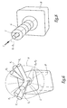
- the surgical device 1 further comprises other components that will be detailed below during the description of a detailed example of using the device for the implantation of a total prosthesis hip 10 shown alone in FIG.
- prosthesis consists of a femoral portion 11 to implant in the femur bone F and a part acetabulum 12 to implant in the pelvic B bone. More specifically, the femoral portion 11 comprises a rod 13 longitudinal axis A-A, intended to be accommodated and retained in a diaphyseal cavity dug in the canal medullary femur F.
- This rod extends in an inclined direction with respect to the axis A-A, in the form of a neck 14 at the free end of which is fixed a truncated spherical head 15, of axis symmetry B-B and corresponding globally to the axis longitudinal neck 14.
- the acetabulum 12 has a 16 acetabulum shape of a substantially hemispherical metal cup intended to be secured to the pelvic bone B.
- the axis of revolution of the concave internal surface of the acetabulum is noted CC.
- an insert 17 also hemispherical axis of C-C revolution, consisting of a plastic material or ceramic.
- the inner surface of the insert 17 is in a manner substantially complementary to the outer surface of the femoral head 15, so that that the latter is articulated in the manner of a kneecap by compared to the cotyloid set 12.
- the prosthesis 10 described above is only given example and other prostheses, geometries and / or of different types, may be implanted by means of device 1, following the surgical method implementation described below.
- the invention applies to the fitting of prostheses whose The acetabular part consists of a single cupule cement to the pelvic bone and in which is articulated directly the prosthetic femoral head or whose part acetabulum comprises, in addition to a first cupule metal to attach to the basin, a second cup mounted in this first cup in an articulated way (we speak then of a cotyloidal set with dual mobility).
- the acetabular part of the prosthesis delimits an axis of revolution for the inner surface concave of the cup to be fixed to the pelvis, similar to the axis C-C.
- the surgeon incises the patient and collects a number of data relating to the anatomical geometry of femur F and pelvis B bones. This effect, different means of acquisition of these data are possible.
- the surgeon uses a probe 9 identified by the computer assembly 2 - sensor 3 and previously calibrated. This probe is brought on remarkable places of bones and, at each of these put in place, the surgeon operates the pedal of command 8 so that the computer 2 records the position of the probe and thereby deduce the anatomical features of femur F and pelvis B.
- computer 2 is able to locate in space the bones femur and pelvis.
- the hip joint is successively dislocated and reduced, the reflective markers 5 and 6 remaining visible for the sensor 3.
- the anatomical head of the femur F is, if necessary, resected.
- a cavity intended for later receive the femoral stem 13 of the prosthesis 10 is hollowed in the diaphysis of the femur F.
- the surgeon first uses a rigid pin not represented that it introduces into the medullary canal anatomical shape of the femur and that it locates in space by means of of the computer set 2 - sensor 3 coming through example palpate one end of this pin carrying a predetermined relief. The surgeon then positions the pin so spotted so that it extends following a diaphyseal X-X direction intended to constitute the axis of implantation of the femoral part 11 of the prosthesis.
- This diaphyseal direction X-X is for example arbitrarily chosen by the surgeon, depending on the shape and condition of the femur.
- the surgeon operates the foot pedal 8 and the computer 2 memorizes the position of the X-X axis, in particular with respect to the femur F.
- This rasp 20 has an active surface of substantially identical to the femoral stem 13. It is equipped with a group of reflective markers 21, analogous to markers 5 or 6, so that the whole computer 2 - sensor 3 allows viewing on the screen display 7 the position of the rasp relative to the femur. The surgeon thus helps this information to guide the rasp along the X-X axis and dig the femoral cavity desired.
- the X-X axis implantation of the femoral part 11 is replaced by the axis of grating actually achieved if it was away from the diaphyseal axis provided by the spindle.
- a cavity C globally hemisphere is dug in the basin B area where is planned implantation of the acetabulum 16 of the prosthesis 10, as shown in Figure 4.
- a first solution is to equip the digging cutter of the cavity of a set of reflective markers similar to markers 5 or 6, so as to record the progression of this strawberry in the pelvic bone and so allow the computer 2, which knows in advance the geometric characteristics of the strawberry used, determine in particular the position of the center O of the cavity countersunk.
- Another solution, which may eventually be combined with the first consists in coming to feel the cavity once it is dug.
- a third solution consists in using a ghost cup equipped with markers reflective analogs to markers 5 or 6 and forthcoming position this ghost cup at the bottom of the cavity countersunk.
- the computer knows the position in the center O space of the cavity C, as well as possibly other geometric characteristics relating to this cavity, especially its radius.
- Phantom Femoral 22 shown in FIG. presenting in a form generally similar to the upper end of the femoral part 11 of the prosthesis 10, with however larger dimensions.
- this femoral component 22, called by the continuation "mega-head" includes a head proper 23 substantially hemispherical axis of symmetry Y-Y.
- the head 23 is secured to an essentially cylindrical neck 24 Y-Y axis.
- the free end of the neck 24 is provided with securing means at the upper free end of the rasp 20, left in place in the diaphysis of the femur F to the end of the grating step.
- the head 23 of the mega-head 22 defines a surface articular 25 substantially identical to the outer surface of the acetabulum 16 of the prosthesis 10 to be implanted.
- the head 23 is thus able to be articulated directly in the cavity Countersink C of the pelvic bone B.
- the position in the space of the mega-head 22, in particular of its axis Y-Y, is known from the computer 2 via the sensors 5 since the mega-head is carried by the handle of the rasp 20 whose position relative to femur F was determined and memorized by the computer during the third time of intervention.
- the surgeon solicits the hip of the patient so that it occupies successively several configurations considered extreme, that is to say configurations that the local morphology of the patient imposes it as natural limits.
- the hip of patient is thus solicited in one or more configurations combining flexion-extension movements, abduction-adduction and / or internal internal rotations, for example in the tailor configuration.
- Each of these extreme configurations characterizes a joint range of motion at the hip of the operated patient that the prosthesis 10 to implant is supposed thereafter reproduce without the risk of being dislocated.
- the surgeon When the surgeon solicits the hip joint in one of these extreme configurations, he actuates the control pedal 8 and the computer set 2 - sensor 3 physically measures and stores the position of the YY axis of the mega-head 22 relative to the pelvic bone B.
- the various positions actually measured are displayed on the screen 7, in particular in the form of symbolic bars Y 1 , Y 2 ..., Y 6 , the basin B being schematically represented by a parallelepiped B 'and the implantation cavity C being represented by a substantially hemispherical hollow C' corresponding, the graphical representations of these elements B 'and C' being a function previous measurements of basin B and cavity C.
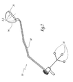
- a cotyloidal ancillary 30 shown only in FIG. 7, which has a 31 phantom cup attached to a Rigid handling handle 32 equipped with markers reflective 33 similar to markers 5 or 6.
- the acetabulum ghost 31 is in the form of a hemisphere delimiting a convex articular surface 34 substantially identical to the external surface of the acetabulum 16 of the prosthesis 10 to implant.
- the axis of generation of this phantom cup is noted Z-Z and is permanently marked in space by the computer set 2 - sensor 3, the computer knowing in advance the fixed geometric relationship between this Z-Z axis and the markers 33.
- the phantom cup 31 is manipulated so as to be housed in the milled cavity C so that its axis ZZ substantially passes through the center O of this cavity.
- the computer 2 displays on its screen 7, in superposition of the bars Y 1 to Y 6 , the prosthetic mobility cone P associated with the prosthesis 10 to be implanted, as a function of the position actually occupied by the phantom cotyle 31 in the cavity C, that is to say according to the position of its axis ZZ.
- the computer 2 knows in advance in advance the structural characteristics of the prosthesis 10, in particular the apex angle of its prosthetic mobility cone, only the position of the axis of revolution of this cone, simulated by the ZZ axis. of the phantom cotyle 31, being adjustable by the surgeon.
- the surgeon then visually compares the position of the bars Y 1 to Y 6 representative of the maximal articular mobility of the hip of the patient with the prosthetic mobility cone P envisaged according to the exact position of the phantom cup 31 in the countersunk cavity C. If, as in FIG. 6, the set of bars Y 1 to Y 6 appears, at the level of the display screen 7, inside the cone P, the position of the axis ZZ is considered acceptable, and that is to say that the prosthesis 10 thus implanted will allow the patient, from the point of view of prosthetic mobility, to limit as much as possible the risk of dislocations of the prosthesis.
- the surgeon moves the phantom cotyle 31 to find a position in which the risk of subsequent dislocations of the prosthesis 10 is strongly limited.
- additional information on the respective angles of the bars Y 1 to Y 6 and ZZ axis can be provided to the surgeon to allow him to find quickly and easily this position.
- other angles of view of the elements of FIG. 6 are advantageously proposed, in particular the angle at which the cone P generally appears in the form of a circle, the graphical representation of the ZZ axis then being directed perpendicular to the plan of view.
- the grater 20 of a femoral test head not shown of geometric dimensions substantially identical to the head femoral 15 of the prosthesis 10.
- This test head is then able to be articulated inside the phantom cotyle 31 which reproduces the internal geometric characteristics of the insert 17 of the prosthesis 10.
- the hip joint thus formed is then reduced and solicited by the surgeon according to different joint configurations extremes, in particular to check that the neck of the head test does not come into contact with the bone Basin B causing dislocation of the prosthesis.
- this ancillary is equipped with means for locating in space, allowing the computer assembly 2 - sensor 3 to display on the screen 7 the position of its impinging direction I, as shown in Figure 8 in which the impactor is symbolized by a tube I '.
- the surgeon positions the impactor so that the direction I, in the extension of the axis CC of the acetabulum, is substantially aligned with the preferred position Z p - Z p of the axis of the prosthetic mobility cone.
- the computer 2 displays a virtual guide tube G, partially hollowed out, inside which the symbolic representation I 'of the impactor must be placed coaxially to ensure the alignment of the directions I and Z p -Z p .
- a visual report such as a color change or blink, signals alignment to the surgeon.
- the insert 17 is then housed in the implanted acetabulum.
- the device 1 according to the invention thus makes it possible position the prosthesis 10 optimally for reproduce as much as possible the cinematic capabilities of the anatomical hip of the operated patient. It should be noted that eight intraoperative times described above are performed during a surgical procedure proper, that is to say during which the patient is for example under anesthesia.
- the various data recorded during the pose of the prosthesis 10 can be used to post-operative assessment and thus allow accurately characterize the joint capabilities of the prosthesis in its implanted state in the bones of the hip. It is also possible to determine the lengthening between femur F and pelvis B during surgery. It will be noted however that the data acquired is much less numerous than those necessary for the operation of a simulator biomechanics of the hip to operate and the means corresponding data of the device according to the invention are therefore less expensive and less complex to manipulate.
- the implantation device 1 is also easily applicable to prostheses of different geometries, only the characteristics of prosthetic mobility being to provide the computer 2 for to display the P cone. strawberries and graters are provided, as well as a game of several ghostheads 31 of sizes and geometries different, able to be secured to one handle 32.
- the use of the cotyloidal ancillary 30 is not essential since the data relating to the prosthetic mobility cone P are known in advance from the computer 2, only the position of the ZZ axis with respect to the cavity C of the pelvis B to be adjusted during surgery to ensure the subsequent operation without dislocation of the prosthesis 10. It is therefore possible that the surgeon uses only virtual representations to adjust the position of this axis ZZ, in displaying the different prosthetic mobility cones which correspond to different positions of the ZZ axis, for example by means of an appropriate computer interface enabling it to modify the position of the virtual axis ZZ and to choose the preferred axis Z p - Z p .
Abstract
Description
- on repère dans l'espace l'os du fémur et l'os du bassin d'un patient à traiter,
- on mesure et on mémorise plusieurs positions d'une direction prothétique fémorale donnée par rapport à une cavité du bassin,
- on compare ces positions mesurées avec le cône de mobilité de la prothèse à implanter, la position de l'axe de révolution de ce cône étant ajustée par rapport à la cavité au cours de l'intervention chirurgicale,
- on détermine au moins une position préférentielle de cet axe de révolution, et
- on impacte une partie cotyloïdienne de la prothèse dans la cavité du bassin suivant ladite position préférentielle.
- la figure 1 est_ une vue schématique d'une partie d'un dispositif chirurgical selon l'invention, appliqué à la hanche d'un patient à opérer ;
- la figure 2 est une vue éclatée en perspective d'une prothèse totale de hanche à implanter au moyen du dispositif de la figure 1 ;
- la figure 3 est une vue schématique en élévation d'une autre partie du dispositif selon l'invention, en cours d'utilisation sur le fémur de la hanche du patient ;
- la figure 4 est une vue en coupe d'une cavité cotyloïdienne creusée dans le bassin de la hanche du patient, au moyen du dispositif selon l'invention ;
- la figure 5 est une vue schématique illustrant la mise en place, à l'intérieur de la cavité de la figure 4, d'un composant fémoral fantôme du dispositif selon l'invention ;
- la figure 6 représente une vue schématique en perspective affichée à l'intention du chirurgien par le dispositif selon l'invention ;
- la figure 7 est une vue en perspective d'un composant cotyloïdien fantôme du dispositif selon l'invention ; et
- la figure 8 représente une autre vue schématique en perspective affichée à l'intention du chirurgien par le dispositif selon l'invention.
- pour supporter la méga-tête 22, le manche de râpe 20 peut être remplacé par une broche fémorale ou par la tige fémorale de la prothèse à implanter, la méga-tête pouvant alors éventuellement être venue de matière avec son support fémoral ;
- la méga-tête 22 décrite ci-dessus peut être remplacée par un composant fémoral fantôme constitué d'une tête de dimensions sensiblement identiques à celles de la tête fémorale prothétique et d'une calotte hémisphérique articulée sur cette tête et de dimensions sensiblement identiques à celles de la partie cotyloïdienne prothétique ;
- les moyens de repérage des os du fémur F et du bassin B ne sont pas limités à des marqueurs réfléchissant l'infra-rouge, des marqueurs sensibles aux ultra-sons ou aux champs électromagnétiques étant par exemple utilisables ;
- la cavité C peut être fraisé après avoir déterminé la direction préférentielle Zp-Zp ; on utilise dans ce cas la cavité anatomique de la hanche comme logement articulaire de la méga-tête 22 pour mesurer les différentes configurations articulaires extrêmes ;
- d'autres moyens qu'un écran d'affichage sont envisageables pour communiquer au chirurgien un retour d'informations sur la comparaison entre les mesures des configurations articulaires extrêmes et le cône de mobilité prothétique ; des indications sonores ou tactiles peuvent ainsi faire comprendre au chirurgien l'état de cette comparaison et le guider dans la détermination de la direction préférentielle Zp-Zp ; et/ou
- la détermination de la direction préférentielle Zp-Zp peut être intégralement assurée par un logiciel approprié équipant l'ordinateur 2, à partir de la comparaison du cône P et des mesures des différentes configurations articulaires extrêmes mesurées en peropératoire, et ce par calcul et extrapolation.
Claims (10)
- Dispositif chirurgical d'implantation d'une prothèse totale de hanche, caractérisé en ce qu'il comporte des moyens (2, 3, 22) de mesure peropératoire et de mémorisation de plusieurs positions d'une direction prothétique fémorale donnée (Y-Y) et des moyens (2) de comparaison peropératoire de ces positions avec le cône (P) de mobilité de la prothèse (10) à implanter, la position de l'axe de révolution (Z-Z) de ce cône étant, lors de l'implantation de la prothèse, ajustable par rapport à la zone (C) du bassin (B) où est prévue l'implantation d'un cotyle (16) de la prothèse.
- Dispositif suivant la revendication 1, caractérisé en ce qu'il comporte des moyens (7) de communication au chirurgien de la comparaison entre les positions de la direction prothétique fémorale (Y-Y) et le cône de mobilité prothétique (P).
- Dispositif suivant la revendication 2, caractérisé en ce que les moyens de communication comportent un moyen d'affichage (7) de représentations symboliques (Y1, ... Y6, P) des positions de la direction prothétique fémorale (Y-Y) et de la position du cône de mobilité prothétique.
- Dispositif suivant l'une quelconque des revendications précédentes, caractérisé en ce qu'il comporte des moyens de sélection (2, 8) par le chirurgien ou de calcul et de mémorisation d'au moins une position préférentielle (Zp-Zp) de l'axe (Z-Z) du cône de mobilité prothétique (P).
- Dispositif suivant la revendication 4, caractérisé en ce qu'il comporte en outre, d'une part, un impacteur de mise en place définitive, dans la zone d'implantation (C) du bassin (B), du cotyle (16) de la prothèse (10), équipé de moyens de repérage dans l'espace et, d'autre part, des moyens (2) de comparaison de la direction d'impaction (I) de cet impacteur avec la position préférentielle (Zp-Zp).
- Dispositif suivant l'une quelconque des revendications précédentes, caractérisé en ce que les moyens de mesure comportent un composant fémoral fantôme (22) définissant la direction prothétique fémorale (Y-Y), des positions de ce composant fémoral par rapport à la zone d'implantation (C) du bassin (B) correspondant aux positions de la direction prothétique fémorale (Y-Y) à comparer au cône de mobilité prothétique (P).
- Dispositif suivant la revendication 6, caractérisé en ce qu'il comporte des moyens de détermination du centre (O) d'une cavité osseuse (C) du bassin (B), constituant la zone d'implantation du bassin et apte à recevoir le composant fémoral fantôme (22) lors de la mesure des différentes positions de ce composant.
- Dispositif suivant l'une des revendications 6 ou 7, caractérisé en ce qu'il comporte un support (20) pour le composant fémoral fantôme (22), adapté pour être relié fixement au fémur (F) et pour porter des moyens (21) de repérage dans l'espace.
- Dispositif suivant l'une quelconque des revendications 6 à 8, caractérisé en ce que le composant fémoral fantôme (22) délimite une surface articulaire (25) apte à être articulée directement sur la zone d'implantation (C) du bassin (B) et sensiblement identique à la surface externe du cotyle (16) de la prothèse (10) à implanter.
- Dispositif suivant l'une quelconque des revendications précédentes, caractérisé en ce qu'il comporte un cotyle fantôme (31) reproduisant l'axe (Z-Z) du cône de mobilité prothétique (P) et équipé d'un moyen (32) de manipulation manuelle par rapport à la zone d'implantation (C) du bassin (B), pourvu de moyens (33) de repérage dans l'espace.
Applications Claiming Priority (2)
| Application Number | Priority Date | Filing Date | Title |
|---|---|---|---|
| FR0401281A FR2865928B1 (fr) | 2004-02-10 | 2004-02-10 | Dispositif chirurgical d'implantation d'une prothese totale de hanche |
| FR0401281 | 2004-02-10 |
Publications (2)
| Publication Number | Publication Date |
|---|---|
| EP1563810A1 true EP1563810A1 (fr) | 2005-08-17 |
| EP1563810B1 EP1563810B1 (fr) | 2010-03-31 |
Family
ID=34685000
Family Applications (1)
| Application Number | Title | Priority Date | Filing Date |
|---|---|---|---|
| EP05356029A Not-in-force EP1563810B1 (fr) | 2004-02-10 | 2005-02-09 | Dispositif chirurgical d'implantation d'une prothèse totale de hanche |
Country Status (6)
| Country | Link |
|---|---|
| US (1) | US7927338B2 (fr) |
| EP (1) | EP1563810B1 (fr) |
| JP (1) | JP4981257B2 (fr) |
| AT (1) | ATE462384T1 (fr) |
| DE (1) | DE602005020204D1 (fr) |
| FR (1) | FR2865928B1 (fr) |
Cited By (31)
| Publication number | Priority date | Publication date | Assignee | Title |
|---|---|---|---|---|
| EP1862151A1 (fr) * | 2006-05-31 | 2007-12-05 | BrainLAB AG | Procédé de sélection d'un implant fémoral |
| EP1911421A1 (fr) * | 2006-09-21 | 2008-04-16 | BrainLAB AG | Procédé et dispositif destinés à la détermination de la modification d'un objet |
| EP2135576A1 (fr) | 2008-06-20 | 2009-12-23 | Tornier | Procédé de modélisation d'une surface glénoïdienne d'une omoplate, dispositif d'implantation d'un composant glénoïdien d'une prothèse d'épaule, et procédé de fabrication d'un tel composant |
| WO2010086571A1 (fr) * | 2009-02-02 | 2010-08-05 | Tornier | Dispositif chirurgical d'implantation d'une prothèse de resurfaçage |
| WO2010111272A1 (fr) * | 2009-03-24 | 2010-09-30 | Biomet Manufacturing Corp. | Appareil pour aligner et fixer un implant par rapport à un patient |
| US7883545B2 (en) | 2006-09-21 | 2011-02-08 | Brainlab Ag | Method and device for determining the change in an object |
| WO2012007841A1 (fr) * | 2010-07-15 | 2012-01-19 | Naviswiss Ag | Procédé de détermination de coordonnées dans l'espace |
| US8167823B2 (en) | 2009-03-24 | 2012-05-01 | Biomet Manufacturing Corp. | Method and apparatus for aligning and securing an implant relative to a patient |
| WO2014197988A1 (fr) * | 2013-06-11 | 2014-12-18 | Orthosoft Inc. | Instrument et procédé de positionnement de prothèse de cupule acétabulaire |
| US9211199B2 (en) | 2009-11-24 | 2015-12-15 | Tornier | Determining implantation configuration for a prosthetic component or application of a resurfacing tool |
| US9247998B2 (en) | 2013-03-15 | 2016-02-02 | Intellijoint Surgical Inc. | System and method for intra-operative leg position measurement |
| US9700329B2 (en) | 2006-02-27 | 2017-07-11 | Biomet Manufacturing, Llc | Patient-specific orthopedic instruments |
| US9763598B2 (en) | 2009-04-27 | 2017-09-19 | Smith & Nephew, Inc. | System and method for identifying a landmark |
| US9827112B2 (en) | 2011-06-16 | 2017-11-28 | Smith & Nephew, Inc. | Surgical alignment using references |
| US9913734B2 (en) | 2006-02-27 | 2018-03-13 | Biomet Manufacturing, Llc | Patient-specific acetabular alignment guides |
| US9968376B2 (en) | 2010-11-29 | 2018-05-15 | Biomet Manufacturing, Llc | Patient-specific orthopedic instruments |
| US10206697B2 (en) | 2006-06-09 | 2019-02-19 | Biomet Manufacturing, Llc | Patient-specific knee alignment guide and associated method |
| US10390845B2 (en) | 2006-02-27 | 2019-08-27 | Biomet Manufacturing, Llc | Patient-specific shoulder guide |
| US10405993B2 (en) | 2013-11-13 | 2019-09-10 | Tornier Sas | Shoulder patient specific instrument |
| US10426492B2 (en) | 2006-02-27 | 2019-10-01 | Biomet Manufacturing, Llc | Patient specific alignment guide with cutting surface and laser indicator |
| US10441435B2 (en) | 2008-12-02 | 2019-10-15 | Intellijoint Surgical Inc. | Method and system for aligning a prosthesis during surgery using active sensors |
| US10507029B2 (en) | 2006-02-27 | 2019-12-17 | Biomet Manufacturing, Llc | Patient-specific acetabular guides and associated instruments |
| US10603179B2 (en) | 2006-02-27 | 2020-03-31 | Biomet Manufacturing, Llc | Patient-specific augments |
| US10722310B2 (en) | 2017-03-13 | 2020-07-28 | Zimmer Biomet CMF and Thoracic, LLC | Virtual surgery planning system and method |
| US10743937B2 (en) | 2006-02-27 | 2020-08-18 | Biomet Manufacturing, Llc | Backup surgical instrument system and method |
| US10893876B2 (en) | 2010-03-05 | 2021-01-19 | Biomet Manufacturing, Llc | Method and apparatus for manufacturing an implant |
| US10959742B2 (en) | 2017-07-11 | 2021-03-30 | Tornier, Inc. | Patient specific humeral cutting guides |
| US11065016B2 (en) | 2015-12-16 | 2021-07-20 | Howmedica Osteonics Corp. | Patient specific instruments and methods for joint prosthesis |
| US11166733B2 (en) | 2017-07-11 | 2021-11-09 | Howmedica Osteonics Corp. | Guides and instruments for improving accuracy of glenoid implant placement |
| US11534313B2 (en) | 2006-02-27 | 2022-12-27 | Biomet Manufacturing, Llc | Patient-specific pre-operative planning |
| US11554019B2 (en) | 2007-04-17 | 2023-01-17 | Biomet Manufacturing, Llc | Method and apparatus for manufacturing an implant |
Families Citing this family (124)
| Publication number | Priority date | Publication date | Assignee | Title |
|---|---|---|---|---|
| FR2768613B1 (fr) * | 1997-09-23 | 1999-12-17 | Tornier Sa | Prothese de genou a plateau rotatoire |
| FR2797178B1 (fr) * | 1999-08-05 | 2002-02-22 | Tornier Sa | Implant malleolaire pour prothese partielle ou totale de cheville et materiel ancillaire de pose d'un tel implant |
| FR2826860B1 (fr) * | 2001-07-09 | 2004-03-05 | Tornier Sa | Ancillaire de pose d'un composant cubital et/ou d'un composant radial de prothese de coude |
| FR2826859B1 (fr) * | 2001-07-09 | 2003-09-19 | Tornier Sa | Ancillaire de pose d'un composant humeral de prothese de coude |
| FR2827500B1 (fr) * | 2001-07-17 | 2004-04-02 | Tornier Sa | Plaque d'osteosynthese de l'extremite superieure de l'humerus |
| US8010180B2 (en) | 2002-03-06 | 2011-08-30 | Mako Surgical Corp. | Haptic guidance system and method |
| US11202676B2 (en) | 2002-03-06 | 2021-12-21 | Mako Surgical Corp. | Neural monitor-based dynamic haptics |
| US7747311B2 (en) | 2002-03-06 | 2010-06-29 | Mako Surgical Corp. | System and method for interactive haptic positioning of a medical device |
| US8996169B2 (en) | 2011-12-29 | 2015-03-31 | Mako Surgical Corp. | Neural monitor-based dynamic haptics |
| FR2848183B1 (fr) * | 2002-12-10 | 2006-01-27 | Tornier Sa | Procede de conditionnement sterile d'un implant prothetique en polyethylene |
| FR2850010B1 (fr) * | 2003-01-17 | 2005-12-02 | Tornier Sa | Ancillaire de pose d'un cotyle prothetique pour une prothese de hanche |
| US7887544B2 (en) | 2003-03-10 | 2011-02-15 | Tornier Sas | Ancillary tool for positioning a glenoid implant |
| FR2854792B1 (fr) * | 2003-05-12 | 2005-09-09 | Tornier Sa | Jeu d'elements prothetiques pour un ensemble prothetique tibial |
| FR2855397B1 (fr) | 2003-05-28 | 2005-07-15 | Tornier Sa | Prothese de coude |
| US7678150B2 (en) | 2004-06-15 | 2010-03-16 | Tornier Sas | Total shoulder prosthesis of an inverted type |
| US8303665B2 (en) | 2004-06-15 | 2012-11-06 | Tornier Sas | Glenoidal component, set of such components and shoulder prosthesis incorporating such a glenoidal component |
| FR2872025B1 (fr) * | 2004-06-28 | 2006-08-25 | Tornier Sas | Prothese d'epaule ou de hanche |
| FR2881340B1 (fr) * | 2005-02-01 | 2008-01-11 | Tornier Sas | Clou humeral |
| EP1843724B1 (fr) * | 2005-02-02 | 2018-07-25 | Össur hf | Systemes et procedes de detection pour la surveillance de la dynamique de marche |
| FR2884408B1 (fr) * | 2005-04-13 | 2007-05-25 | Tornier Sas | Dispositif chirurgical d'implantation d'une prothese partielle ou totale de genou |
| FR2884407B1 (fr) * | 2005-04-13 | 2007-05-25 | Tornier Sas | Dispositif chirurgical d'implantation d'une prothese partielle ou totale du genou |
| US7468077B2 (en) * | 2005-08-02 | 2008-12-23 | Tornier Sas | Patellar retractor and method of surgical procedure on knee |
| FR2896404B1 (fr) * | 2006-01-24 | 2008-02-29 | Tornier Sas | Ensemble d'instrumentation chirurgicale pour poser une prothese de cheville |
| FR2896684B1 (fr) * | 2006-02-01 | 2008-09-26 | Tornier Soc Par Actions Simplifiee | Implant tibial a tige offset |
| US8092465B2 (en) | 2006-06-09 | 2012-01-10 | Biomet Manufacturing Corp. | Patient specific knee alignment guide and associated method |
| US20080257363A1 (en) * | 2007-04-17 | 2008-10-23 | Biomet Manufacturing Corp. | Method And Apparatus For Manufacturing An Implant |
| US8377066B2 (en) | 2006-02-27 | 2013-02-19 | Biomet Manufacturing Corp. | Patient-specific elbow guides and associated methods |
| US8864769B2 (en) | 2006-02-27 | 2014-10-21 | Biomet Manufacturing, Llc | Alignment guides with patient-specific anchoring elements |
| US8282646B2 (en) | 2006-02-27 | 2012-10-09 | Biomet Manufacturing Corp. | Patient specific knee alignment guide and associated method |
| US8608749B2 (en) | 2006-02-27 | 2013-12-17 | Biomet Manufacturing, Llc | Patient-specific acetabular guides and associated instruments |
| US8568487B2 (en) | 2006-02-27 | 2013-10-29 | Biomet Manufacturing, Llc | Patient-specific hip joint devices |
| US8473305B2 (en) | 2007-04-17 | 2013-06-25 | Biomet Manufacturing Corp. | Method and apparatus for manufacturing an implant |
| US8858561B2 (en) | 2006-06-09 | 2014-10-14 | Blomet Manufacturing, LLC | Patient-specific alignment guide |
| US8298237B2 (en) | 2006-06-09 | 2012-10-30 | Biomet Manufacturing Corp. | Patient-specific alignment guide for multiple incisions |
| US9113971B2 (en) | 2006-02-27 | 2015-08-25 | Biomet Manufacturing, Llc | Femoral acetabular impingement guide |
| US8133234B2 (en) | 2006-02-27 | 2012-03-13 | Biomet Manufacturing Corp. | Patient specific acetabular guide and method |
| US8608748B2 (en) | 2006-02-27 | 2013-12-17 | Biomet Manufacturing, Llc | Patient specific guides |
| US8241293B2 (en) | 2006-02-27 | 2012-08-14 | Biomet Manufacturing Corp. | Patient specific high tibia osteotomy |
| US10278711B2 (en) | 2006-02-27 | 2019-05-07 | Biomet Manufacturing, Llc | Patient-specific femoral guide |
| US8070752B2 (en) | 2006-02-27 | 2011-12-06 | Biomet Manufacturing Corp. | Patient specific alignment guide and inter-operative adjustment |
| US8535387B2 (en) | 2006-02-27 | 2013-09-17 | Biomet Manufacturing, Llc | Patient-specific tools and implants |
| US7967868B2 (en) | 2007-04-17 | 2011-06-28 | Biomet Manufacturing Corp. | Patient-modified implant and associated method |
| FR2899790B1 (fr) | 2006-04-13 | 2008-06-13 | Tornier Sas | Composant glenoidien pour prothese totale d'epaule, jeu de tels composants, et prothese totale d'epaule comprenant un tel composant |
| FR2900045B1 (fr) | 2006-04-21 | 2009-01-16 | Tornier Sas | Prothese d'epaule ou de hanche |
| WO2008044679A1 (fr) * | 2006-10-10 | 2008-04-17 | Saga University | Système de soutien chirurgical |
| FR2906999B1 (fr) | 2006-10-13 | 2009-06-05 | Tornier Sas | Ensemble prothetique de cheville |
| CA2671523C (fr) * | 2006-12-07 | 2013-02-12 | Anatol Podolsky | Procede et appareil pour un remplacement de hanche total |
| US8579985B2 (en) | 2006-12-07 | 2013-11-12 | Ihip Surgical, Llc | Method and apparatus for hip replacement |
| US8974540B2 (en) | 2006-12-07 | 2015-03-10 | Ihip Surgical, Llc | Method and apparatus for attachment in a modular hip replacement or fracture fixation device |
| US8784425B2 (en) | 2007-02-28 | 2014-07-22 | Smith & Nephew, Inc. | Systems and methods for identifying landmarks on orthopedic implants |
| US8814868B2 (en) | 2007-02-28 | 2014-08-26 | Smith & Nephew, Inc. | Instrumented orthopaedic implant for identifying a landmark |
| EP1982676B1 (fr) * | 2007-04-03 | 2012-07-11 | Finsbury (Development) Limited | Appareil et système |
| US8265949B2 (en) | 2007-09-27 | 2012-09-11 | Depuy Products, Inc. | Customized patient surgical plan |
| EP2957240A1 (fr) | 2007-09-30 | 2015-12-23 | DePuy Products, Inc. | Instrument chirurgical orthopédique personnalisé spécifique d'un patient |
| US8357111B2 (en) | 2007-09-30 | 2013-01-22 | Depuy Products, Inc. | Method and system for designing patient-specific orthopaedic surgical instruments |
| EP2227719B1 (fr) * | 2007-11-19 | 2020-01-08 | Blue Ortho | Repérage d'implant de la hanche en chirurgie assistée par ordinateur |
| US9220514B2 (en) | 2008-02-28 | 2015-12-29 | Smith & Nephew, Inc. | System and method for identifying a landmark |
| GB0803725D0 (en) * | 2008-02-29 | 2008-04-09 | Depuy Int Ltd | Surgical apparatus and procedure |
| FR2932677B1 (fr) | 2008-06-20 | 2010-06-25 | Univ Bretagne Occidentale | Systeme d'aide a l'implantation d'une prothese de hanche sur un individu. |
| GB0820219D0 (en) * | 2008-11-05 | 2008-12-10 | Imp Innovations Ltd | Hip resurfacing |
| US8170641B2 (en) | 2009-02-20 | 2012-05-01 | Biomet Manufacturing Corp. | Method of imaging an extremity of a patient |
| US9031637B2 (en) | 2009-04-27 | 2015-05-12 | Smith & Nephew, Inc. | Targeting an orthopaedic implant landmark |
| EP2429421B1 (fr) | 2009-05-06 | 2015-06-24 | Blue Ortho | Système de fixation moins effractif pour des traceurs en chirurgie assistée par ordinateur |
| WO2011001292A1 (fr) * | 2009-06-30 | 2011-01-06 | Blue Ortho | Guide ajustable pour chirurgie orthopédique assistée par ordinateur |
| DE102009028503B4 (de) | 2009-08-13 | 2013-11-14 | Biomet Manufacturing Corp. | Resektionsschablone zur Resektion von Knochen, Verfahren zur Herstellung einer solchen Resektionsschablone und Operationsset zur Durchführung von Kniegelenk-Operationen |
| US8632547B2 (en) | 2010-02-26 | 2014-01-21 | Biomet Sports Medicine, Llc | Patient-specific osteotomy devices and methods |
| US9066727B2 (en) | 2010-03-04 | 2015-06-30 | Materialise Nv | Patient-specific computed tomography guides |
| BR112012030791A2 (pt) | 2010-06-03 | 2016-11-01 | Smith & Nephew Inc | implantes ortopédicos |
| EP2582328B1 (fr) | 2010-06-18 | 2017-09-13 | Howmedica Osteonics Corp. | Arthroplastie totale de la hanche spécifique au patient |
| EP2422754B1 (fr) * | 2010-08-27 | 2014-11-05 | Greatbatch Medical SA | Impacteur décalé pour coupelle avec une plaque de saisie pour implants à mobilité double |
| US9271744B2 (en) | 2010-09-29 | 2016-03-01 | Biomet Manufacturing, Llc | Patient-specific guide for partial acetabular socket replacement |
| FR2966343B1 (fr) | 2010-10-22 | 2012-12-07 | Tornier Sa | Jeu de composants glenoidiens d'une prothese d'epaule |
| CA2815654C (fr) | 2010-10-29 | 2019-02-19 | The Cleveland Clinic Foundation | Systeme et methode facilitant la fixation d'un implant pret a l'emploi dans un tissu chez un patient |
| CA2821670A1 (fr) | 2010-12-17 | 2012-06-21 | Avenir Medical Inc. | Procede et systeme d'alignement d'une prothese durant une intervention chirurgicale |
| US9713539B2 (en) | 2011-01-20 | 2017-07-25 | Brainlab Ag | Method for planning positioning of a ball joint prosthesis |
| EP2665434B1 (fr) | 2011-01-20 | 2017-08-02 | Brainlab AG | Procédé pour planifier le positionnement d'une prothèse d'articulation sphérique |
| US8890511B2 (en) | 2011-01-25 | 2014-11-18 | Smith & Nephew, Inc. | Targeting operation sites |
| US9241745B2 (en) | 2011-03-07 | 2016-01-26 | Biomet Manufacturing, Llc | Patient-specific femoral version guide |
| US8715289B2 (en) | 2011-04-15 | 2014-05-06 | Biomet Manufacturing, Llc | Patient-specific numerically controlled instrument |
| US9675400B2 (en) | 2011-04-19 | 2017-06-13 | Biomet Manufacturing, Llc | Patient-specific fracture fixation instrumentation and method |
| US8668700B2 (en) | 2011-04-29 | 2014-03-11 | Biomet Manufacturing, Llc | Patient-specific convertible guides |
| US8956364B2 (en) | 2011-04-29 | 2015-02-17 | Biomet Manufacturing, Llc | Patient-specific partial knee guides and other instruments |
| BR112013028627A2 (pt) | 2011-05-06 | 2017-01-24 | Smith & Nephew Inc | limites-alvo de dispositivos ortopédicos |
| US8532807B2 (en) | 2011-06-06 | 2013-09-10 | Biomet Manufacturing, Llc | Pre-operative planning and manufacturing method for orthopedic procedure |
| US9084618B2 (en) | 2011-06-13 | 2015-07-21 | Biomet Manufacturing, Llc | Drill guides for confirming alignment of patient-specific alignment guides |
| US8764760B2 (en) | 2011-07-01 | 2014-07-01 | Biomet Manufacturing, Llc | Patient-specific bone-cutting guidance instruments and methods |
| US20130001121A1 (en) | 2011-07-01 | 2013-01-03 | Biomet Manufacturing Corp. | Backup kit for a patient-specific arthroplasty kit assembly |
| US8597365B2 (en) | 2011-08-04 | 2013-12-03 | Biomet Manufacturing, Llc | Patient-specific pelvic implants for acetabular reconstruction |
| US9066734B2 (en) | 2011-08-31 | 2015-06-30 | Biomet Manufacturing, Llc | Patient-specific sacroiliac guides and associated methods |
| US9295497B2 (en) | 2011-08-31 | 2016-03-29 | Biomet Manufacturing, Llc | Patient-specific sacroiliac and pedicle guides |
| US9386993B2 (en) | 2011-09-29 | 2016-07-12 | Biomet Manufacturing, Llc | Patient-specific femoroacetabular impingement instruments and methods |
| US9554910B2 (en) | 2011-10-27 | 2017-01-31 | Biomet Manufacturing, Llc | Patient-specific glenoid guide and implants |
| US9301812B2 (en) | 2011-10-27 | 2016-04-05 | Biomet Manufacturing, Llc | Methods for patient-specific shoulder arthroplasty |
| EP2770918B1 (fr) | 2011-10-27 | 2017-07-19 | Biomet Manufacturing, LLC | Guides glénoïdes spécifiques d'un patient |
| US9451973B2 (en) | 2011-10-27 | 2016-09-27 | Biomet Manufacturing, Llc | Patient specific glenoid guide |
| KR20130046337A (ko) | 2011-10-27 | 2013-05-07 | 삼성전자주식회사 | 멀티뷰 디바이스 및 그 제어방법과, 디스플레이장치 및 그 제어방법과, 디스플레이 시스템 |
| US9237950B2 (en) | 2012-02-02 | 2016-01-19 | Biomet Manufacturing, Llc | Implant with patient-specific porous structure |
| US9314188B2 (en) | 2012-04-12 | 2016-04-19 | Intellijoint Surgical Inc. | Computer-assisted joint replacement surgery and navigation systems |
| US9204977B2 (en) | 2012-12-11 | 2015-12-08 | Biomet Manufacturing, Llc | Patient-specific acetabular guide for anterior approach |
| US9060788B2 (en) | 2012-12-11 | 2015-06-23 | Biomet Manufacturing, Llc | Patient-specific acetabular guide for anterior approach |
| US9839438B2 (en) | 2013-03-11 | 2017-12-12 | Biomet Manufacturing, Llc | Patient-specific glenoid guide with a reusable guide holder |
| US9579107B2 (en) | 2013-03-12 | 2017-02-28 | Biomet Manufacturing, Llc | Multi-point fit for patient specific guide |
| US9498233B2 (en) | 2013-03-13 | 2016-11-22 | Biomet Manufacturing, Llc. | Universal acetabular guide and associated hardware |
| US9826981B2 (en) | 2013-03-13 | 2017-11-28 | Biomet Manufacturing, Llc | Tangential fit of patient-specific guides |
| US9517145B2 (en) | 2013-03-15 | 2016-12-13 | Biomet Manufacturing, Llc | Guide alignment system and method |
| US20140276872A1 (en) | 2013-03-15 | 2014-09-18 | Otismed Corporation | Customized acetabular cup positioning guide and system and method of generating and employing such a guide |
| US20150112349A1 (en) | 2013-10-21 | 2015-04-23 | Biomet Manufacturing, Llc | Ligament Guide Registration |
| US10282488B2 (en) | 2014-04-25 | 2019-05-07 | Biomet Manufacturing, Llc | HTO guide with optional guided ACL/PCL tunnels |
| US9408616B2 (en) | 2014-05-12 | 2016-08-09 | Biomet Manufacturing, Llc | Humeral cut guide |
| US9681960B2 (en) | 2014-05-16 | 2017-06-20 | Howmedica Osteonics Corp. | Guides for fracture system |
| US10575968B2 (en) | 2014-05-16 | 2020-03-03 | Howmedica Osteonics Corp. | Guides for fracture system |
| US9561040B2 (en) | 2014-06-03 | 2017-02-07 | Biomet Manufacturing, Llc | Patient-specific glenoid depth control |
| US9839436B2 (en) | 2014-06-03 | 2017-12-12 | Biomet Manufacturing, Llc | Patient-specific glenoid depth control |
| US9833245B2 (en) | 2014-09-29 | 2017-12-05 | Biomet Sports Medicine, Llc | Tibial tubercule osteotomy |
| US9826994B2 (en) | 2014-09-29 | 2017-11-28 | Biomet Manufacturing, Llc | Adjustable glenoid pin insertion guide |
| US9820868B2 (en) | 2015-03-30 | 2017-11-21 | Biomet Manufacturing, Llc | Method and apparatus for a pin apparatus |
| US10226262B2 (en) | 2015-06-25 | 2019-03-12 | Biomet Manufacturing, Llc | Patient-specific humeral guide designs |
| US10568647B2 (en) | 2015-06-25 | 2020-02-25 | Biomet Manufacturing, Llc | Patient-specific humeral guide designs |
| CN105559884B (zh) * | 2016-02-04 | 2018-10-23 | 清华大学 | 一种全髋关节置换手术中骨盆姿态获取方法与系统 |
| EP3484398A1 (fr) | 2016-07-15 | 2019-05-22 | MAKO Surgical Corp. | Procédure de révision assistée par robot. |
| US20200405505A1 (en) * | 2018-04-29 | 2020-12-31 | Duggan Innovations Llc | Joint Replacement And In Situ Gauge System |
| US11051829B2 (en) | 2018-06-26 | 2021-07-06 | DePuy Synthes Products, Inc. | Customized patient-specific orthopaedic surgical instrument |
| EP3738542A1 (fr) * | 2019-05-15 | 2020-11-18 | Stryker European Holdings I, LLC | Unité de poursuite pour un système de navigation chirurgical |
| CN111214316A (zh) * | 2019-11-21 | 2020-06-02 | 南京冬尚生物科技有限公司 | 一种人工髋关节压力测量仪 |
Citations (11)
| Publication number | Priority date | Publication date | Assignee | Title |
|---|---|---|---|---|
| FR2770128A1 (fr) * | 1997-10-24 | 1999-04-30 | Aesculap Sa | Systeme de prothese de hanche |
| DE20016635U1 (de) * | 2000-09-26 | 2001-02-22 | Brainlab Ag | System zur navigationsgestützten Ausrichtung von Elementen |
| US6205411B1 (en) | 1997-02-21 | 2001-03-20 | Carnegie Mellon University | Computer-assisted surgery planner and intra-operative guidance system |
| WO2002002028A1 (fr) * | 2000-07-06 | 2002-01-10 | Synthes Ag Chur | Procede et dispositif de detection de collision |
| US20020077540A1 (en) * | 2000-11-17 | 2002-06-20 | Kienzle Thomas C. | Enhanced graphic features for computer assisted surgery system |
| WO2002080824A1 (fr) * | 2001-04-06 | 2002-10-17 | Iversen Bjoern Franc | Insertion assistee par ordinateur d'une articulation de hanche artificielle |
| DE20213711U1 (de) * | 2002-09-05 | 2003-01-02 | Aesculap Ag & Co Kg | Vorrichtung zur Bestimmung der geometrischen Daten einer kugeligen Ausnehmung |
| DE20304153U1 (de) * | 2003-03-15 | 2003-05-22 | Aesculap Ag & Co Kg | Vorrichtung zur Bestimmung geometrischer Daten an einem Beckenknochen |
| US20030153829A1 (en) * | 2002-02-13 | 2003-08-14 | Kinamed, Inc. | Non-imaging, computer assisted navigation system for hip replacement surgery |
| WO2004001569A2 (fr) * | 2002-06-21 | 2003-12-31 | Cedara Software Corp. | Systeme et procede assistes par ordinateur de remplacement de hanche, de remplacement partiel de genou et de remplacement complet de genou a invasion minimale |
| DE20315005U1 (de) * | 2003-09-27 | 2004-01-22 | Aesculap Ag & Co. Kg | Vorrichtung zur Bestimmung der Beweglichkeit einer Hüftgelenkprothese |
Family Cites Families (66)
| Publication number | Priority date | Publication date | Assignee | Title |
|---|---|---|---|---|
| FR2669213A1 (fr) | 1990-11-19 | 1992-05-22 | Tornier Sa | Prothese femorale partiellement cimentee. |
| FR2681240A1 (fr) | 1991-09-12 | 1993-03-19 | Tornier Sa | Prothese totale de poignet. |
| FR2684290B1 (fr) | 1991-11-29 | 1994-01-21 | Tornier Ets | Prothese du genou. |
| FR2685633B1 (fr) | 1991-12-27 | 1998-02-27 | Tornier Sa | Prothese humerale modulaire. |
| FR2691357A1 (fr) | 1992-05-25 | 1993-11-26 | Tornier Sa | Prothèse totale pour l'articulation métacarpo-phalangienne. |
| FR2703240B1 (fr) | 1993-03-30 | 1995-06-02 | Tornier Sa | Prothèse cotyloïdienne élastiquement déformable. |
| FR2705226B1 (fr) | 1993-05-17 | 1995-07-07 | Tornier Sa | Fixateur de rachis pour le maintien d'une colonne vertébrale. |
| FR2709412B1 (fr) | 1993-09-01 | 1995-11-24 | Tornier Sa | Vis pour fixateur lombo-sacré. |
| FR2711505B1 (fr) | 1993-10-25 | 1995-12-29 | Tornier Sa | Dispositif de synthèse des fractures de l'extrémité supérieure du fémur. |
| FR2724553B1 (fr) | 1994-09-15 | 1996-12-20 | Tornier Sa | Fixateur externe ou interne destine a la reparation des fractures ou des arthroplasties du squelette |
| FR2727002B1 (fr) | 1994-11-18 | 1997-01-03 | Tornier Sa | Prothese humerale a sphere |
| FR2728159B1 (fr) | 1994-12-16 | 1997-06-27 | Tornier Sa | Prothese discale elastique |
| FR2735356B1 (fr) | 1995-06-16 | 1997-11-28 | Tornier Sa | Implant cotyloidien destine notamment a la cavite articulaire iliaque |
| FR2741796B1 (fr) | 1995-11-30 | 1998-03-27 | Tornier Sa | Dispositif pour la fixation d'une prothese et notamment d'une prothese glenoidienne de l'omoplate |
| US5682886A (en) | 1995-12-26 | 1997-11-04 | Musculographics Inc | Computer-assisted surgical system |
| FR2743716B1 (fr) | 1996-01-23 | 1998-04-10 | Tornier Sa | Prothese tibiale |
| FR2747302B1 (fr) | 1996-04-11 | 1998-09-11 | Tornier Sa | Prothese de cheville |
| FR2750037B1 (fr) | 1996-06-25 | 1998-11-27 | Tornier Sa | Prothese d'epaule monobloc |
| FR2751868B1 (fr) | 1996-08-02 | 1999-04-16 | Tornier Sa | Prothese ajouree de l'extremite superieure de l'humerus |
| FR2758455B1 (fr) | 1997-01-23 | 1999-08-06 | Tornier Sa | Prothese totale de coude |
| US5880976A (en) * | 1997-02-21 | 1999-03-09 | Carnegie Mellon University | Apparatus and method for facilitating the implantation of artificial components in joints |
| FR2760353B1 (fr) | 1997-03-10 | 1999-07-02 | Tornier Sa | Prothese de cheville |
| JP3075998B2 (ja) * | 1997-03-21 | 2000-08-14 | 有限会社日本整形機器 | 人工関節取付器 |
| FR2768330B1 (fr) | 1997-09-12 | 2000-01-21 | Tornier Sa | Prothese humeral a sphere indexee |
| FR2768613B1 (fr) | 1997-09-23 | 1999-12-17 | Tornier Sa | Prothese de genou a plateau rotatoire |
| FR2768922B1 (fr) | 1997-10-01 | 2000-01-14 | Tornier Sa | Prothese destinee a etre ancree dans un os long |
| FR2769495B1 (fr) | 1997-10-14 | 1999-12-31 | Michel Timoteo | Prothese de genou |
| FR2769494B1 (fr) | 1997-10-14 | 1999-12-31 | Michel Timoteo | Piece femorale pour prothese de genou |
| FR2772259B1 (fr) | 1997-12-12 | 2000-03-03 | Tornier Sa | Perfectionnements apportes aux protheses totales de genou comportant un element femoral et un plateau tibial |
| FR2775586B1 (fr) | 1998-03-03 | 2000-06-30 | Tornier Sa | Implant acetabulaire ou cotyloidien modulaire |
| FR2777442B1 (fr) | 1998-04-21 | 2000-07-28 | Tornier Sa | Ancre de suture a expansion reversible |
| FR2777447B1 (fr) | 1998-04-21 | 2000-07-28 | Tornier Sa | Dispositif de fixation reversible pour la mise en place d'un implant dans l'os |
| FR2777443B1 (fr) | 1998-04-21 | 2000-06-30 | Tornier Sa | Ancillaire pour la mise en place et le retrait d'un implant et plus particulierement d'une ancre de suture |
| FR2793404B1 (fr) | 1999-05-14 | 2001-09-14 | Tornier Sa | Prothese de coude |
| FR2794641B1 (fr) | 1999-06-09 | 2001-11-23 | Tornier Sa | Prothese humerale |
| FR2797178B1 (fr) | 1999-08-05 | 2002-02-22 | Tornier Sa | Implant malleolaire pour prothese partielle ou totale de cheville et materiel ancillaire de pose d'un tel implant |
| FR2816200A1 (fr) | 2000-11-06 | 2002-05-10 | Praxim | Determination de la position d'une prothese du genou |
| FR2826860B1 (fr) | 2001-07-09 | 2004-03-05 | Tornier Sa | Ancillaire de pose d'un composant cubital et/ou d'un composant radial de prothese de coude |
| FR2826859B1 (fr) | 2001-07-09 | 2003-09-19 | Tornier Sa | Ancillaire de pose d'un composant humeral de prothese de coude |
| FR2827500B1 (fr) | 2001-07-17 | 2004-04-02 | Tornier Sa | Plaque d'osteosynthese de l'extremite superieure de l'humerus |
| FR2831426B1 (fr) | 2001-10-30 | 2004-07-16 | Tornier Sa | Implant rotulien et prothese de genou incorporant un tel implant |
| FR2835425B1 (fr) | 2002-02-04 | 2004-04-09 | Tornier Sa | Element prothetique comprenant deux composants et procede d'assemblage d'un tel element prothetique |
| FR2836039B1 (fr) | 2002-02-15 | 2004-10-01 | Tornier Sa | Composant glenoidien de prothese d'epaule et prothese totale d'epaule incorporant un tel composant |
| US7048741B2 (en) | 2002-05-10 | 2006-05-23 | Swanson Todd V | Method and apparatus for minimally invasive knee arthroplasty |
| FR2841768B1 (fr) | 2002-07-05 | 2005-05-06 | Tornier Sa | Prothese d'epaule ou de hanche facilitant l'abduction |
| EP1402855B1 (fr) * | 2002-09-24 | 2004-09-01 | BrainLAB AG | Appareil et méthode pour déterminer le débattement d'une articulation |
| JP2006509609A (ja) * | 2002-10-04 | 2006-03-23 | オルトソフト インコーポレイテッド | コンピュータ支援の人工股関節置換手術 |
| FR2848183B1 (fr) | 2002-12-10 | 2006-01-27 | Tornier Sa | Procede de conditionnement sterile d'un implant prothetique en polyethylene |
| FR2850010B1 (fr) * | 2003-01-17 | 2005-12-02 | Tornier Sa | Ancillaire de pose d'un cotyle prothetique pour une prothese de hanche |
| US7887544B2 (en) | 2003-03-10 | 2011-02-15 | Tornier Sas | Ancillary tool for positioning a glenoid implant |
| FR2854792B1 (fr) | 2003-05-12 | 2005-09-09 | Tornier Sa | Jeu d'elements prothetiques pour un ensemble prothetique tibial |
| FR2855397B1 (fr) | 2003-05-28 | 2005-07-15 | Tornier Sa | Prothese de coude |
| US7559931B2 (en) | 2003-06-09 | 2009-07-14 | OrthAlign, Inc. | Surgical orientation system and method |
| WO2004112610A2 (fr) | 2003-06-09 | 2004-12-29 | Vitruvian Orthopaedics, Llc | Dispositif et procede d'orientation chirurgicale |
| FR2859099B1 (fr) | 2003-08-25 | 2006-01-06 | Tornier Sa | Composant glenoidien de prothese d'epaule et prothese totale d'epaule incorporant un tel composant |
| FR2863865B1 (fr) | 2003-12-19 | 2006-10-06 | Tornier Sa | Prothese d'epaule ou de hanche et son procede de montage |
| US20050281465A1 (en) * | 2004-02-04 | 2005-12-22 | Joel Marquart | Method and apparatus for computer assistance with total hip replacement procedure |
| US20080287781A1 (en) * | 2004-03-05 | 2008-11-20 | Depuy International Limited | Registration Methods and Apparatus |
| FR2871371B1 (fr) * | 2004-06-15 | 2007-04-06 | Tornier Sas | Composant glenoidien de prothese d'epaule, jeu d'elements constitutifs d'un tel composant et prothese totale d'epaule incorporant un tel composant |
| US7678150B2 (en) * | 2004-06-15 | 2010-03-16 | Tornier Sas | Total shoulder prosthesis of an inverted type |
| US8303665B2 (en) * | 2004-06-15 | 2012-11-06 | Tornier Sas | Glenoidal component, set of such components and shoulder prosthesis incorporating such a glenoidal component |
| FR2871368B1 (fr) * | 2004-06-15 | 2006-08-25 | Tornier Sas | Jeu de composants humeraux pour prothese totale d'epaule |
| FR2872025B1 (fr) * | 2004-06-28 | 2006-08-25 | Tornier Sas | Prothese d'epaule ou de hanche |
| FR2881340B1 (fr) * | 2005-02-01 | 2008-01-11 | Tornier Sas | Clou humeral |
| FR2884408B1 (fr) * | 2005-04-13 | 2007-05-25 | Tornier Sas | Dispositif chirurgical d'implantation d'une prothese partielle ou totale de genou |
| US20070162142A1 (en) | 2005-06-15 | 2007-07-12 | Vitruvian Orthopaedics, Llc | Knee surgery method and apparatus |
-
2004
- 2004-02-10 FR FR0401281A patent/FR2865928B1/fr not_active Expired - Fee Related
-
2005
- 2005-02-09 DE DE602005020204T patent/DE602005020204D1/de active Active
- 2005-02-09 EP EP05356029A patent/EP1563810B1/fr not_active Not-in-force
- 2005-02-09 AT AT05356029T patent/ATE462384T1/de not_active IP Right Cessation
- 2005-02-10 JP JP2005034441A patent/JP4981257B2/ja not_active Expired - Fee Related
- 2005-02-10 US US11/054,618 patent/US7927338B2/en not_active Expired - Fee Related
Patent Citations (11)
| Publication number | Priority date | Publication date | Assignee | Title |
|---|---|---|---|---|
| US6205411B1 (en) | 1997-02-21 | 2001-03-20 | Carnegie Mellon University | Computer-assisted surgery planner and intra-operative guidance system |
| FR2770128A1 (fr) * | 1997-10-24 | 1999-04-30 | Aesculap Sa | Systeme de prothese de hanche |
| WO2002002028A1 (fr) * | 2000-07-06 | 2002-01-10 | Synthes Ag Chur | Procede et dispositif de detection de collision |
| DE20016635U1 (de) * | 2000-09-26 | 2001-02-22 | Brainlab Ag | System zur navigationsgestützten Ausrichtung von Elementen |
| US20020077540A1 (en) * | 2000-11-17 | 2002-06-20 | Kienzle Thomas C. | Enhanced graphic features for computer assisted surgery system |
| WO2002080824A1 (fr) * | 2001-04-06 | 2002-10-17 | Iversen Bjoern Franc | Insertion assistee par ordinateur d'une articulation de hanche artificielle |
| US20030153829A1 (en) * | 2002-02-13 | 2003-08-14 | Kinamed, Inc. | Non-imaging, computer assisted navigation system for hip replacement surgery |
| WO2004001569A2 (fr) * | 2002-06-21 | 2003-12-31 | Cedara Software Corp. | Systeme et procede assistes par ordinateur de remplacement de hanche, de remplacement partiel de genou et de remplacement complet de genou a invasion minimale |
| DE20213711U1 (de) * | 2002-09-05 | 2003-01-02 | Aesculap Ag & Co Kg | Vorrichtung zur Bestimmung der geometrischen Daten einer kugeligen Ausnehmung |
| DE20304153U1 (de) * | 2003-03-15 | 2003-05-22 | Aesculap Ag & Co Kg | Vorrichtung zur Bestimmung geometrischer Daten an einem Beckenknochen |
| DE20315005U1 (de) * | 2003-09-27 | 2004-01-22 | Aesculap Ag & Co. Kg | Vorrichtung zur Bestimmung der Beweglichkeit einer Hüftgelenkprothese |
Cited By (62)
| Publication number | Priority date | Publication date | Assignee | Title |
|---|---|---|---|---|
| US10426492B2 (en) | 2006-02-27 | 2019-10-01 | Biomet Manufacturing, Llc | Patient specific alignment guide with cutting surface and laser indicator |
| US10390845B2 (en) | 2006-02-27 | 2019-08-27 | Biomet Manufacturing, Llc | Patient-specific shoulder guide |
| US10507029B2 (en) | 2006-02-27 | 2019-12-17 | Biomet Manufacturing, Llc | Patient-specific acetabular guides and associated instruments |
| US10603179B2 (en) | 2006-02-27 | 2020-03-31 | Biomet Manufacturing, Llc | Patient-specific augments |
| US10743937B2 (en) | 2006-02-27 | 2020-08-18 | Biomet Manufacturing, Llc | Backup surgical instrument system and method |
| US9913734B2 (en) | 2006-02-27 | 2018-03-13 | Biomet Manufacturing, Llc | Patient-specific acetabular alignment guides |
| US9700329B2 (en) | 2006-02-27 | 2017-07-11 | Biomet Manufacturing, Llc | Patient-specific orthopedic instruments |
| US11534313B2 (en) | 2006-02-27 | 2022-12-27 | Biomet Manufacturing, Llc | Patient-specific pre-operative planning |
| EP1862151A1 (fr) * | 2006-05-31 | 2007-12-05 | BrainLAB AG | Procédé de sélection d'un implant fémoral |
| US7822588B2 (en) | 2006-05-31 | 2010-10-26 | Brainlab Ag | Surface replacement of a femoral head |
| US10893879B2 (en) | 2006-06-09 | 2021-01-19 | Biomet Manufacturing, Llc | Patient-specific knee alignment guide and associated method |
| US10206697B2 (en) | 2006-06-09 | 2019-02-19 | Biomet Manufacturing, Llc | Patient-specific knee alignment guide and associated method |
| US11576689B2 (en) | 2006-06-09 | 2023-02-14 | Biomet Manufacturing, Llc | Patient-specific knee alignment guide and associated method |
| EP1911421A1 (fr) * | 2006-09-21 | 2008-04-16 | BrainLAB AG | Procédé et dispositif destinés à la détermination de la modification d'un objet |
| US7883545B2 (en) | 2006-09-21 | 2011-02-08 | Brainlab Ag | Method and device for determining the change in an object |
| US11554019B2 (en) | 2007-04-17 | 2023-01-17 | Biomet Manufacturing, Llc | Method and apparatus for manufacturing an implant |
| US10716676B2 (en) | 2008-06-20 | 2020-07-21 | Tornier Sas | Method for modeling a glenoid surface of a scapula, apparatus for implanting a glenoid component of a shoulder prosthesis, and method for producing such a component |
| US11432930B2 (en) | 2008-06-20 | 2022-09-06 | Tornier Sas | Method for modeling a glenoid surface of a scapula, apparatus for implanting a glenoid component of a shoulder prosthesis, and method for producing such a component |
| EP2135576A1 (fr) | 2008-06-20 | 2009-12-23 | Tornier | Procédé de modélisation d'une surface glénoïdienne d'une omoplate, dispositif d'implantation d'un composant glénoïdien d'une prothèse d'épaule, et procédé de fabrication d'un tel composant |
| FR2932674A1 (fr) * | 2008-06-20 | 2009-12-25 | Tornier Sa | Procede de modelisation d'une surface glenoidienne d'une omoplate, dispositif d'implantation d'un composant glenoidien d'une prothese d'epaule, et procede de fabrication d'un tel compose. |
| US8932361B2 (en) | 2008-06-20 | 2015-01-13 | Tornier Sas | Method for modeling a glenoid surface of a scapula, apparatus for implanting a glenoid component of a shoulder prosthesis, and method for producing such a component |
| US10441435B2 (en) | 2008-12-02 | 2019-10-15 | Intellijoint Surgical Inc. | Method and system for aligning a prosthesis during surgery using active sensors |
| WO2010086571A1 (fr) * | 2009-02-02 | 2010-08-05 | Tornier | Dispositif chirurgical d'implantation d'une prothèse de resurfaçage |
| FR2941613A1 (fr) * | 2009-02-02 | 2010-08-06 | Tornier Sa | Dispositif chirurgical d'implantation d'une prothese de resurfacage. |
| US9468538B2 (en) | 2009-03-24 | 2016-10-18 | Biomet Manufacturing, Llc | Method and apparatus for aligning and securing an implant relative to a patient |
| WO2010111272A1 (fr) * | 2009-03-24 | 2010-09-30 | Biomet Manufacturing Corp. | Appareil pour aligner et fixer un implant par rapport à un patient |
| US8337426B2 (en) | 2009-03-24 | 2012-12-25 | Biomet Manufacturing Corp. | Method and apparatus for aligning and securing an implant relative to a patient |
| US8167823B2 (en) | 2009-03-24 | 2012-05-01 | Biomet Manufacturing Corp. | Method and apparatus for aligning and securing an implant relative to a patient |
| US9763598B2 (en) | 2009-04-27 | 2017-09-19 | Smith & Nephew, Inc. | System and method for identifying a landmark |
| US11324522B2 (en) | 2009-10-01 | 2022-05-10 | Biomet Manufacturing, Llc | Patient specific alignment guide with cutting surface and laser indicator |
| US9211199B2 (en) | 2009-11-24 | 2015-12-15 | Tornier | Determining implantation configuration for a prosthetic component or application of a resurfacing tool |
| US10195036B2 (en) | 2009-11-24 | 2019-02-05 | Tornier | Determining implantation configuration for a prosthetic component or application of a resurfacing tool |
| US11911277B2 (en) | 2009-11-24 | 2024-02-27 | Tornier Sas | Determining implantation configuration for a prosthetic component or application of a resurfacing tool |
| US10695185B2 (en) | 2009-11-24 | 2020-06-30 | Tornier | Determining implantation configuration for a prosthetic component or application of a resurfacing tool |
| US9575931B2 (en) | 2009-11-24 | 2017-02-21 | Tornier | Determining implantation configuration for a prosthetic component or application of a resurfacing tool |
| US10893876B2 (en) | 2010-03-05 | 2021-01-19 | Biomet Manufacturing, Llc | Method and apparatus for manufacturing an implant |
| WO2012007841A1 (fr) * | 2010-07-15 | 2012-01-19 | Naviswiss Ag | Procédé de détermination de coordonnées dans l'espace |
| US11234719B2 (en) | 2010-11-03 | 2022-02-01 | Biomet Manufacturing, Llc | Patient-specific shoulder guide |
| US9968376B2 (en) | 2010-11-29 | 2018-05-15 | Biomet Manufacturing, Llc | Patient-specific orthopedic instruments |
| US11103363B2 (en) | 2011-06-16 | 2021-08-31 | Smith & Nephew, Inc. | Surgical alignment using references |
| US9827112B2 (en) | 2011-06-16 | 2017-11-28 | Smith & Nephew, Inc. | Surgical alignment using references |
| US10881468B2 (en) | 2013-03-15 | 2021-01-05 | Intellijoint Surgical Inc. | Systems and methods to compute a subluxation between two bones |
| US9655749B2 (en) | 2013-03-15 | 2017-05-23 | Intelligent Surgical Inc. | Sterile optical sensor system having an adjustment mechanism |
| US10194996B2 (en) | 2013-03-15 | 2019-02-05 | Intellijoint Surgical Inc. | Systems and methods to compute a positional change between two bones |
| US11839436B2 (en) | 2013-03-15 | 2023-12-12 | Intellijoint Surgical Inc. | Methods and kit for a navigated procedure |
| US11826113B2 (en) | 2013-03-15 | 2023-11-28 | Intellijoint Surgical Inc. | Systems and methods to compute a subluxation between two bones |
| US11589930B2 (en) | 2013-03-15 | 2023-02-28 | Intellijoint Surgical Inc. | Systems and methods to compute a subluxation between two bones |
| US9247998B2 (en) | 2013-03-15 | 2016-02-02 | Intellijoint Surgical Inc. | System and method for intra-operative leg position measurement |
| US11090170B2 (en) | 2013-06-11 | 2021-08-17 | Orthosoft Ulc | Acetabular cup prosthesis positioning instrument and method |
| US9987148B2 (en) | 2013-06-11 | 2018-06-05 | Orthosoft Inc. | Acetabular cup prosthesis positioning instrument and method |
| WO2014197988A1 (fr) * | 2013-06-11 | 2014-12-18 | Orthosoft Inc. | Instrument et procédé de positionnement de prothèse de cupule acétabulaire |
| US11179249B2 (en) | 2013-11-13 | 2021-11-23 | Tornier Sas | Shoulder patient specific instrument |
| US10405993B2 (en) | 2013-11-13 | 2019-09-10 | Tornier Sas | Shoulder patient specific instrument |
| US11065016B2 (en) | 2015-12-16 | 2021-07-20 | Howmedica Osteonics Corp. | Patient specific instruments and methods for joint prosthesis |
| US10722310B2 (en) | 2017-03-13 | 2020-07-28 | Zimmer Biomet CMF and Thoracic, LLC | Virtual surgery planning system and method |
| US11399851B2 (en) | 2017-07-11 | 2022-08-02 | Howmedica Osteonics Corp. | Guides and instruments for improving accuracy of glenoid implant placement |
| US11278299B2 (en) | 2017-07-11 | 2022-03-22 | Howmedica Osteonics Corp | Guides and instruments for improving accuracy of glenoid implant placement |
| US11234721B2 (en) | 2017-07-11 | 2022-02-01 | Howmedica Osteonics Corp. | Guides and instruments for improving accuracy of glenoid implant placement |
| US11166733B2 (en) | 2017-07-11 | 2021-11-09 | Howmedica Osteonics Corp. | Guides and instruments for improving accuracy of glenoid implant placement |
| US10959742B2 (en) | 2017-07-11 | 2021-03-30 | Tornier, Inc. | Patient specific humeral cutting guides |
| US11076873B2 (en) | 2017-07-11 | 2021-08-03 | Howmedica Osteonics Corp. | Patient specific humeral cutting guides |
| US11918239B2 (en) | 2017-07-11 | 2024-03-05 | Howmedica Osteonics Corp. | Guides and instruments for improving accuracy of glenoid implant placement |
Also Published As
| Publication number | Publication date |
|---|---|
| US20050203536A1 (en) | 2005-09-15 |
| FR2865928A1 (fr) | 2005-08-12 |
| DE602005020204D1 (de) | 2010-05-12 |
| FR2865928B1 (fr) | 2006-03-17 |
| ATE462384T1 (de) | 2010-04-15 |
| JP2005224613A (ja) | 2005-08-25 |
| US7927338B2 (en) | 2011-04-19 |
| JP4981257B2 (ja) | 2012-07-18 |
| EP1563810B1 (fr) | 2010-03-31 |
Similar Documents
| Publication | Publication Date | Title |
|---|---|---|
| EP1563810B1 (fr) | Dispositif chirurgical d'implantation d'une prothèse totale de hanche | |
| EP1712192B1 (fr) | Dispositif chirurgical d'implantation d'une prothèse partielle ou totale de genou | |
| EP1450696B1 (fr) | Dispositif pour la mise en oeuvre d'un procédé de sélection d'éléments de prothèse de genou | |
| US8007448B2 (en) | System and method for performing arthroplasty of a joint and tracking a plumb line plane | |
| US6944518B2 (en) | Customized prosthesis and method of designing and manufacturing a customized prosthesis by utilizing computed tomography data | |
| WO2009153355A2 (fr) | Systeme d'aide a l'implantation d'une prothese de hanche sur un individu | |
| US20190021866A1 (en) | Patient-specific glenoid implant | |
| EP2135576B1 (fr) | Procédé de modélisation d'une surface glénoïdienne d'une omoplate, dispositif d'implantation d'un composant glénoïdien d'une prothèse d'épaule, et procédé de fabrication d'un tel composant | |
| EP1712193A1 (fr) | Dispositif chirurgical d'implantation d'une prothése partielle ou totale de genou | |
| JP5468012B2 (ja) | 人工デバイス、および人工デバイスを受け入れるように骨を調整するためのシステム | |
| EP1662997B1 (fr) | Systeme destine a la numerisation d'informations relatives a la position et a l'orientation de composants d'une prothese de la hanche | |
| US20050251065A1 (en) | Planning method and planning device for knee implants | |
| EP3576666A1 (fr) | Procede et dispositif d'assistance a la pose d'une prothese, notamment de hanche, par un chirurgien suivant differents protocoles chirurgicaux | |
| EP2324801B1 (fr) | Dispositif et procédé de détermination d'une configuration d'implantation d'un composant prothétique glénoïdien ou d'une configuration d'application d'un outil de resurfaçage glénoïdien | |
| US11478362B2 (en) | Robotic surgery system for augmented hip arthroplasty procedures | |
| CA3087673A1 (fr) | Arthroplastique total de la hanche a spheres concentriques anatomiques | |
| WO2022171805A1 (fr) | Système et procédé pour concevoir un implant personnalisé | |
| CN113332008B (zh) | 一种髋关节置换术中股骨长度的确定方法及系统 | |
| FR2941613A1 (fr) | Dispositif chirurgical d'implantation d'une prothese de resurfacage. | |
| US20240008993A1 (en) | Stemless orthopedic implants with sensors | |
| WO2015197800A1 (fr) | Dispositif d'aide au positionnement d'un instrument et/ou d'un implant prothetique comprenant un premier guide tridimensionnel et un deuxieme guide multifonction | |
| CN117881356A (zh) | 使用摄影测量法和深度学习来推荐假体植入物的部件类型的系统和方法 | |
| FR3036516A1 (fr) | Procede de simulation d'implantation | |
| WO2007093695A1 (fr) | Instrument d'assistance a la navigation de la pose d'implants chirurgicaux et kits le comprenant |
Legal Events
| Date | Code | Title | Description |
|---|---|---|---|
| PUAI | Public reference made under article 153(3) epc to a published international application that has entered the european phase |
Free format text: ORIGINAL CODE: 0009012 |
|
| AK | Designated contracting states |
Kind code of ref document: A1 Designated state(s): AT BE BG CH CY CZ DE DK EE ES FI FR GB GR HU IE IS IT LI LT LU MC NL PL PT RO SE SI SK TR |
|
| AX | Request for extension of the european patent |
Extension state: AL BA HR LV MK YU |
|
| 17P | Request for examination filed |
Effective date: 20051222 |
|
| AKX | Designation fees paid |
Designated state(s): AT BE BG CH CY CZ DE DK EE ES FI FR GB GR HU IE IS IT LI LT LU MC NL PL PT RO SE SI SK TR |
|
| 17Q | First examination report despatched |
Effective date: 20071218 |
|
| GRAP | Despatch of communication of intention to grant a patent |
Free format text: ORIGINAL CODE: EPIDOSNIGR1 |
|
| GRAS | Grant fee paid |
Free format text: ORIGINAL CODE: EPIDOSNIGR3 |
|
| GRAA | (expected) grant |
Free format text: ORIGINAL CODE: 0009210 |
|
| AK | Designated contracting states |
Kind code of ref document: B1 Designated state(s): AT BE BG CH CY CZ DE DK EE ES FI FR GB GR HU IE IS IT LI LT LU MC NL PL PT RO SE SI SK TR |
|
| REG | Reference to a national code |
Ref country code: GB Ref legal event code: FG4D Free format text: NOT ENGLISH Ref country code: CH Ref legal event code: EP |
|
| REG | Reference to a national code |
Ref country code: IE Ref legal event code: FG4D |
|
| REF | Corresponds to: |
Ref document number: 602005020204 Country of ref document: DE Date of ref document: 20100512 Kind code of ref document: P |
|
| REG | Reference to a national code |
Ref country code: NL Ref legal event code: VDEP Effective date: 20100331 |
|
| PG25 | Lapsed in a contracting state [announced via postgrant information from national office to epo] |
Ref country code: LT Free format text: LAPSE BECAUSE OF FAILURE TO SUBMIT A TRANSLATION OF THE DESCRIPTION OR TO PAY THE FEE WITHIN THE PRESCRIBED TIME-LIMIT Effective date: 20100331 |
|
| LTIE | Lt: invalidation of european patent or patent extension |
Effective date: 20100331 |
|
| PG25 | Lapsed in a contracting state [announced via postgrant information from national office to epo] |
Ref country code: SI Free format text: LAPSE BECAUSE OF FAILURE TO SUBMIT A TRANSLATION OF THE DESCRIPTION OR TO PAY THE FEE WITHIN THE PRESCRIBED TIME-LIMIT Effective date: 20100331 Ref country code: PL Free format text: LAPSE BECAUSE OF FAILURE TO SUBMIT A TRANSLATION OF THE DESCRIPTION OR TO PAY THE FEE WITHIN THE PRESCRIBED TIME-LIMIT Effective date: 20100331 Ref country code: FI Free format text: LAPSE BECAUSE OF FAILURE TO SUBMIT A TRANSLATION OF THE DESCRIPTION OR TO PAY THE FEE WITHIN THE PRESCRIBED TIME-LIMIT Effective date: 20100331 Ref country code: AT Free format text: LAPSE BECAUSE OF FAILURE TO SUBMIT A TRANSLATION OF THE DESCRIPTION OR TO PAY THE FEE WITHIN THE PRESCRIBED TIME-LIMIT Effective date: 20100331 |
|
| PG25 | Lapsed in a contracting state [announced via postgrant information from national office to epo] |
Ref country code: NL Free format text: LAPSE BECAUSE OF FAILURE TO SUBMIT A TRANSLATION OF THE DESCRIPTION OR TO PAY THE FEE WITHIN THE PRESCRIBED TIME-LIMIT Effective date: 20100331 Ref country code: CY Free format text: LAPSE BECAUSE OF FAILURE TO SUBMIT A TRANSLATION OF THE DESCRIPTION OR TO PAY THE FEE WITHIN THE PRESCRIBED TIME-LIMIT Effective date: 20100331 Ref country code: EE Free format text: LAPSE BECAUSE OF FAILURE TO SUBMIT A TRANSLATION OF THE DESCRIPTION OR TO PAY THE FEE WITHIN THE PRESCRIBED TIME-LIMIT Effective date: 20100331 Ref country code: ES Free format text: LAPSE BECAUSE OF FAILURE TO SUBMIT A TRANSLATION OF THE DESCRIPTION OR TO PAY THE FEE WITHIN THE PRESCRIBED TIME-LIMIT Effective date: 20100712 Ref country code: RO Free format text: LAPSE BECAUSE OF FAILURE TO SUBMIT A TRANSLATION OF THE DESCRIPTION OR TO PAY THE FEE WITHIN THE PRESCRIBED TIME-LIMIT Effective date: 20100331 Ref country code: SE Free format text: LAPSE BECAUSE OF FAILURE TO SUBMIT A TRANSLATION OF THE DESCRIPTION OR TO PAY THE FEE WITHIN THE PRESCRIBED TIME-LIMIT Effective date: 20100331 |
|
| PG25 | Lapsed in a contracting state [announced via postgrant information from national office to epo] |
Ref country code: SK Free format text: LAPSE BECAUSE OF FAILURE TO SUBMIT A TRANSLATION OF THE DESCRIPTION OR TO PAY THE FEE WITHIN THE PRESCRIBED TIME-LIMIT Effective date: 20100331 Ref country code: IS Free format text: LAPSE BECAUSE OF FAILURE TO SUBMIT A TRANSLATION OF THE DESCRIPTION OR TO PAY THE FEE WITHIN THE PRESCRIBED TIME-LIMIT Effective date: 20100731 Ref country code: CZ Free format text: LAPSE BECAUSE OF FAILURE TO SUBMIT A TRANSLATION OF THE DESCRIPTION OR TO PAY THE FEE WITHIN THE PRESCRIBED TIME-LIMIT Effective date: 20100331 |
|
| PG25 | Lapsed in a contracting state [announced via postgrant information from national office to epo] |
Ref country code: DK Free format text: LAPSE BECAUSE OF FAILURE TO SUBMIT A TRANSLATION OF THE DESCRIPTION OR TO PAY THE FEE WITHIN THE PRESCRIBED TIME-LIMIT Effective date: 20100331 Ref country code: PT Free format text: LAPSE BECAUSE OF FAILURE TO SUBMIT A TRANSLATION OF THE DESCRIPTION OR TO PAY THE FEE WITHIN THE PRESCRIBED TIME-LIMIT Effective date: 20100802 |
|
| PLBE | No opposition filed within time limit |
Free format text: ORIGINAL CODE: 0009261 |
|
| STAA | Information on the status of an ep patent application or granted ep patent |
Free format text: STATUS: NO OPPOSITION FILED WITHIN TIME LIMIT |
|
| 26N | No opposition filed |
Effective date: 20110104 |
|
| PG25 | Lapsed in a contracting state [announced via postgrant information from national office to epo] |
Ref country code: IT Free format text: LAPSE BECAUSE OF FAILURE TO SUBMIT A TRANSLATION OF THE DESCRIPTION OR TO PAY THE FEE WITHIN THE PRESCRIBED TIME-LIMIT Effective date: 20100331 |
|
| BERE | Be: lapsed |
Owner name: TORNIER Effective date: 20110228 |
|
| PG25 | Lapsed in a contracting state [announced via postgrant information from national office to epo] |
Ref country code: MC Free format text: LAPSE BECAUSE OF NON-PAYMENT OF DUE FEES Effective date: 20110228 |
|
| PG25 | Lapsed in a contracting state [announced via postgrant information from national office to epo] |
Ref country code: BE Free format text: LAPSE BECAUSE OF NON-PAYMENT OF DUE FEES Effective date: 20110228 |
|
| PGFP | Annual fee paid to national office [announced via postgrant information from national office to epo] |
Ref country code: CH Payment date: 20120321 Year of fee payment: 8 Ref country code: IE Payment date: 20120123 Year of fee payment: 8 |
|
| REG | Reference to a national code |
Ref country code: DE Ref legal event code: R082 Ref document number: 602005020204 Country of ref document: DE Representative=s name: DREISS PATENTANWAELTE PARTNERSCHAFT, DE |
|
| REG | Reference to a national code |
Ref country code: CH Ref legal event code: PCOW Free format text: NEW ADDRESS: 161 RUE LAVOISIER, 38330 MONTBONNOT-SAINT-MARTIN (FR) |
|
| REG | Reference to a national code |
Ref country code: FR Ref legal event code: CA Effective date: 20121213 |
|
| REG | Reference to a national code |
Ref country code: DE Ref legal event code: R082 Ref document number: 602005020204 Country of ref document: DE Representative=s name: DREISS PATENTANWAELTE PARTNERSCHAFT, DE Effective date: 20121126 Ref country code: DE Ref legal event code: R081 Ref document number: 602005020204 Country of ref document: DE Owner name: TORNIER, FR Free format text: FORMER OWNER: TORNIER, SAINT-ISMIER, FR Effective date: 20121126 Ref country code: DE Ref legal event code: R082 Ref document number: 602005020204 Country of ref document: DE Representative=s name: DREISS PATENTANWAELTE PARTG MBB, DE Effective date: 20121126 Ref country code: DE Ref legal event code: R081 Ref document number: 602005020204 Country of ref document: DE Owner name: CORIN LIMITED, CIRENCESTER, GB Free format text: FORMER OWNER: TORNIER, SAINT-ISMIER, FR Effective date: 20121126 Ref country code: DE Ref legal event code: R082 Ref document number: 602005020204 Country of ref document: DE Representative=s name: BECKER, KURIG, STRAUS, DE Effective date: 20121126 |
|
| PG25 | Lapsed in a contracting state [announced via postgrant information from national office to epo] |
Ref country code: LU Free format text: LAPSE BECAUSE OF NON-PAYMENT OF DUE FEES Effective date: 20110209 |
|
| REG | Reference to a national code |
Ref country code: FR Ref legal event code: GC Effective date: 20130515 |
|
| PG25 | Lapsed in a contracting state [announced via postgrant information from national office to epo] |
Ref country code: TR Free format text: LAPSE BECAUSE OF FAILURE TO SUBMIT A TRANSLATION OF THE DESCRIPTION OR TO PAY THE FEE WITHIN THE PRESCRIBED TIME-LIMIT Effective date: 20100331 Ref country code: BG Free format text: LAPSE BECAUSE OF FAILURE TO SUBMIT A TRANSLATION OF THE DESCRIPTION OR TO PAY THE FEE WITHIN THE PRESCRIBED TIME-LIMIT Effective date: 20100630 |
|
| REG | Reference to a national code |
Ref country code: CH Ref legal event code: PL |
|
| PG25 | Lapsed in a contracting state [announced via postgrant information from national office to epo] |
Ref country code: CH Free format text: LAPSE BECAUSE OF NON-PAYMENT OF DUE FEES Effective date: 20130228 Ref country code: HU Free format text: LAPSE BECAUSE OF FAILURE TO SUBMIT A TRANSLATION OF THE DESCRIPTION OR TO PAY THE FEE WITHIN THE PRESCRIBED TIME-LIMIT Effective date: 20100331 Ref country code: LI Free format text: LAPSE BECAUSE OF NON-PAYMENT OF DUE FEES Effective date: 20130228 |
|
| REG | Reference to a national code |
Ref country code: IE Ref legal event code: MM4A |
|
| PG25 | Lapsed in a contracting state [announced via postgrant information from national office to epo] |
Ref country code: IE Free format text: LAPSE BECAUSE OF NON-PAYMENT OF DUE FEES Effective date: 20130209 |
|
| PG25 | Lapsed in a contracting state [announced via postgrant information from national office to epo] |
Ref country code: GR Free format text: LAPSE BECAUSE OF FAILURE TO SUBMIT A TRANSLATION OF THE DESCRIPTION OR TO PAY THE FEE WITHIN THE PRESCRIBED TIME-LIMIT Effective date: 20100331 |
|
| REG | Reference to a national code |
Ref country code: FR Ref legal event code: PLFP Year of fee payment: 11 |
|
| REG | Reference to a national code |
Ref country code: FR Ref legal event code: PLFP Year of fee payment: 12 |
|
| REG | Reference to a national code |
Ref country code: FR Ref legal event code: RG Effective date: 20160128 |
|
| REG | Reference to a national code |
Ref country code: DE Ref legal event code: R082 Ref document number: 602005020204 Country of ref document: DE Representative=s name: BECKER KURIG & PARTNER PATENTANWAELTE MBB, DE Ref country code: DE Ref legal event code: R082 Ref document number: 602005020204 Country of ref document: DE Representative=s name: BECKER & KURIG PARTNERSCHAFT PATENTANWAELTE MB, DE Ref country code: DE Ref legal event code: R082 Ref document number: 602005020204 Country of ref document: DE Representative=s name: BECKER & KURIG PARTNERSCHAFT PATENTANWAELTE PA, DE Ref country code: DE Ref legal event code: R082 Ref document number: 602005020204 Country of ref document: DE Representative=s name: BECKER, KURIG, STRAUS, DE Ref country code: DE Ref legal event code: R081 Ref document number: 602005020204 Country of ref document: DE Owner name: CORIN LIMITED, CIRENCESTER, GB Free format text: FORMER OWNER: TORNIER, MONTBONNOT-SAINT-MARTIN, FR |
|
| REG | Reference to a national code |
Ref country code: GB Ref legal event code: 732E Free format text: REGISTERED BETWEEN 20170119 AND 20170125 |
|
| REG | Reference to a national code |
Ref country code: FR Ref legal event code: PLFP Year of fee payment: 13 |
|
| REG | Reference to a national code |
Ref country code: FR Ref legal event code: TP Owner name: CORIN LIMITED, GB Effective date: 20170619 |
|
| REG | Reference to a national code |
Ref country code: FR Ref legal event code: PLFP Year of fee payment: 14 |
|
| PGFP | Annual fee paid to national office [announced via postgrant information from national office to epo] |
Ref country code: FR Payment date: 20210226 Year of fee payment: 17 |
|
| PGFP | Annual fee paid to national office [announced via postgrant information from national office to epo] |
Ref country code: DE Payment date: 20210226 Year of fee payment: 17 Ref country code: GB Payment date: 20210224 Year of fee payment: 17 |
|
| REG | Reference to a national code |
Ref country code: DE Ref legal event code: R119 Ref document number: 602005020204 Country of ref document: DE |
|
| GBPC | Gb: european patent ceased through non-payment of renewal fee |
Effective date: 20220209 |
|
| PG25 | Lapsed in a contracting state [announced via postgrant information from national office to epo] |
Ref country code: FR Free format text: LAPSE BECAUSE OF NON-PAYMENT OF DUE FEES Effective date: 20220228 |
|
| PG25 | Lapsed in a contracting state [announced via postgrant information from national office to epo] |
Ref country code: GB Free format text: LAPSE BECAUSE OF NON-PAYMENT OF DUE FEES Effective date: 20220209 Ref country code: DE Free format text: LAPSE BECAUSE OF NON-PAYMENT OF DUE FEES Effective date: 20220901 |