EP1563810B1 - Surgical apparatus for implanting a total hip prosthesis - Google Patents
Surgical apparatus for implanting a total hip prosthesis Download PDFInfo
- Publication number
- EP1563810B1 EP1563810B1 EP05356029A EP05356029A EP1563810B1 EP 1563810 B1 EP1563810 B1 EP 1563810B1 EP 05356029 A EP05356029 A EP 05356029A EP 05356029 A EP05356029 A EP 05356029A EP 1563810 B1 EP1563810 B1 EP 1563810B1
- Authority
- EP
- European Patent Office
- Prior art keywords
- prosthesis
- cone
- positions
- axis
- femoral
- Prior art date
- Legal status (The legal status is an assumption and is not a legal conclusion. Google has not performed a legal analysis and makes no representation as to the accuracy of the status listed.)
- Not-in-force
Links
Images


Classifications
-
- A—HUMAN NECESSITIES
- A61—MEDICAL OR VETERINARY SCIENCE; HYGIENE
- A61B—DIAGNOSIS; SURGERY; IDENTIFICATION
- A61B34/00—Computer-aided surgery; Manipulators or robots specially adapted for use in surgery
- A61B34/20—Surgical navigation systems; Devices for tracking or guiding surgical instruments, e.g. for frameless stereotaxis
-
- A—HUMAN NECESSITIES
- A61—MEDICAL OR VETERINARY SCIENCE; HYGIENE
- A61F—FILTERS IMPLANTABLE INTO BLOOD VESSELS; PROSTHESES; DEVICES PROVIDING PATENCY TO, OR PREVENTING COLLAPSING OF, TUBULAR STRUCTURES OF THE BODY, e.g. STENTS; ORTHOPAEDIC, NURSING OR CONTRACEPTIVE DEVICES; FOMENTATION; TREATMENT OR PROTECTION OF EYES OR EARS; BANDAGES, DRESSINGS OR ABSORBENT PADS; FIRST-AID KITS
- A61F2/00—Filters implantable into blood vessels; Prostheses, i.e. artificial substitutes or replacements for parts of the body; Appliances for connecting them with the body; Devices providing patency to, or preventing collapsing of, tubular structures of the body, e.g. stents
- A61F2/02—Prostheses implantable into the body
- A61F2/30—Joints
- A61F2/46—Special tools or methods for implanting or extracting artificial joints, accessories, bone grafts or substitutes, or particular adaptations therefor
- A61F2/4657—Measuring instruments used for implanting artificial joints
-
- A—HUMAN NECESSITIES
- A61—MEDICAL OR VETERINARY SCIENCE; HYGIENE
- A61F—FILTERS IMPLANTABLE INTO BLOOD VESSELS; PROSTHESES; DEVICES PROVIDING PATENCY TO, OR PREVENTING COLLAPSING OF, TUBULAR STRUCTURES OF THE BODY, e.g. STENTS; ORTHOPAEDIC, NURSING OR CONTRACEPTIVE DEVICES; FOMENTATION; TREATMENT OR PROTECTION OF EYES OR EARS; BANDAGES, DRESSINGS OR ABSORBENT PADS; FIRST-AID KITS
- A61F2/00—Filters implantable into blood vessels; Prostheses, i.e. artificial substitutes or replacements for parts of the body; Appliances for connecting them with the body; Devices providing patency to, or preventing collapsing of, tubular structures of the body, e.g. stents
- A61F2/02—Prostheses implantable into the body
- A61F2/30—Joints
- A61F2/46—Special tools or methods for implanting or extracting artificial joints, accessories, bone grafts or substitutes, or particular adaptations therefor
- A61F2/4684—Trial or dummy prostheses
-
- G—PHYSICS
- G06—COMPUTING; CALCULATING OR COUNTING
- G06T—IMAGE DATA PROCESSING OR GENERATION, IN GENERAL
- G06T7/00—Image analysis
- G06T7/70—Determining position or orientation of objects or cameras
- G06T7/73—Determining position or orientation of objects or cameras using feature-based methods
-
- A—HUMAN NECESSITIES
- A61—MEDICAL OR VETERINARY SCIENCE; HYGIENE
- A61B—DIAGNOSIS; SURGERY; IDENTIFICATION
- A61B34/00—Computer-aided surgery; Manipulators or robots specially adapted for use in surgery
- A61B34/10—Computer-aided planning, simulation or modelling of surgical operations
- A61B2034/101—Computer-aided simulation of surgical operations
- A61B2034/102—Modelling of surgical devices, implants or prosthesis
-
- A—HUMAN NECESSITIES
- A61—MEDICAL OR VETERINARY SCIENCE; HYGIENE
- A61B—DIAGNOSIS; SURGERY; IDENTIFICATION
- A61B34/00—Computer-aided surgery; Manipulators or robots specially adapted for use in surgery
- A61B34/10—Computer-aided planning, simulation or modelling of surgical operations
- A61B2034/101—Computer-aided simulation of surgical operations
- A61B2034/105—Modelling of the patient, e.g. for ligaments or bones
-
- A—HUMAN NECESSITIES
- A61—MEDICAL OR VETERINARY SCIENCE; HYGIENE
- A61B—DIAGNOSIS; SURGERY; IDENTIFICATION
- A61B34/00—Computer-aided surgery; Manipulators or robots specially adapted for use in surgery
- A61B34/20—Surgical navigation systems; Devices for tracking or guiding surgical instruments, e.g. for frameless stereotaxis
- A61B2034/2046—Tracking techniques
- A61B2034/2055—Optical tracking systems
-
- A—HUMAN NECESSITIES
- A61—MEDICAL OR VETERINARY SCIENCE; HYGIENE
- A61B—DIAGNOSIS; SURGERY; IDENTIFICATION
- A61B34/00—Computer-aided surgery; Manipulators or robots specially adapted for use in surgery
- A61B34/20—Surgical navigation systems; Devices for tracking or guiding surgical instruments, e.g. for frameless stereotaxis
- A61B2034/2072—Reference field transducer attached to an instrument or patient
-
- A—HUMAN NECESSITIES
- A61—MEDICAL OR VETERINARY SCIENCE; HYGIENE
- A61B—DIAGNOSIS; SURGERY; IDENTIFICATION
- A61B34/00—Computer-aided surgery; Manipulators or robots specially adapted for use in surgery
- A61B34/10—Computer-aided planning, simulation or modelling of surgical operations
-
- A—HUMAN NECESSITIES
- A61—MEDICAL OR VETERINARY SCIENCE; HYGIENE
- A61F—FILTERS IMPLANTABLE INTO BLOOD VESSELS; PROSTHESES; DEVICES PROVIDING PATENCY TO, OR PREVENTING COLLAPSING OF, TUBULAR STRUCTURES OF THE BODY, e.g. STENTS; ORTHOPAEDIC, NURSING OR CONTRACEPTIVE DEVICES; FOMENTATION; TREATMENT OR PROTECTION OF EYES OR EARS; BANDAGES, DRESSINGS OR ABSORBENT PADS; FIRST-AID KITS
- A61F2/00—Filters implantable into blood vessels; Prostheses, i.e. artificial substitutes or replacements for parts of the body; Appliances for connecting them with the body; Devices providing patency to, or preventing collapsing of, tubular structures of the body, e.g. stents
- A61F2/02—Prostheses implantable into the body
- A61F2/30—Joints
- A61F2/32—Joints for the hip
- A61F2/34—Acetabular cups
-
- A—HUMAN NECESSITIES
- A61—MEDICAL OR VETERINARY SCIENCE; HYGIENE
- A61F—FILTERS IMPLANTABLE INTO BLOOD VESSELS; PROSTHESES; DEVICES PROVIDING PATENCY TO, OR PREVENTING COLLAPSING OF, TUBULAR STRUCTURES OF THE BODY, e.g. STENTS; ORTHOPAEDIC, NURSING OR CONTRACEPTIVE DEVICES; FOMENTATION; TREATMENT OR PROTECTION OF EYES OR EARS; BANDAGES, DRESSINGS OR ABSORBENT PADS; FIRST-AID KITS
- A61F2/00—Filters implantable into blood vessels; Prostheses, i.e. artificial substitutes or replacements for parts of the body; Appliances for connecting them with the body; Devices providing patency to, or preventing collapsing of, tubular structures of the body, e.g. stents
- A61F2/02—Prostheses implantable into the body
- A61F2/30—Joints
- A61F2/32—Joints for the hip
- A61F2/36—Femoral heads ; Femoral endoprostheses
- A61F2/3662—Femoral shafts
-
- A—HUMAN NECESSITIES
- A61—MEDICAL OR VETERINARY SCIENCE; HYGIENE
- A61F—FILTERS IMPLANTABLE INTO BLOOD VESSELS; PROSTHESES; DEVICES PROVIDING PATENCY TO, OR PREVENTING COLLAPSING OF, TUBULAR STRUCTURES OF THE BODY, e.g. STENTS; ORTHOPAEDIC, NURSING OR CONTRACEPTIVE DEVICES; FOMENTATION; TREATMENT OR PROTECTION OF EYES OR EARS; BANDAGES, DRESSINGS OR ABSORBENT PADS; FIRST-AID KITS
- A61F2/00—Filters implantable into blood vessels; Prostheses, i.e. artificial substitutes or replacements for parts of the body; Appliances for connecting them with the body; Devices providing patency to, or preventing collapsing of, tubular structures of the body, e.g. stents
- A61F2/02—Prostheses implantable into the body
- A61F2/30—Joints
- A61F2/46—Special tools or methods for implanting or extracting artificial joints, accessories, bone grafts or substitutes, or particular adaptations therefor
- A61F2/4603—Special tools or methods for implanting or extracting artificial joints, accessories, bone grafts or substitutes, or particular adaptations therefor for insertion or extraction of endoprosthetic joints or of accessories thereof
- A61F2/4607—Special tools or methods for implanting or extracting artificial joints, accessories, bone grafts or substitutes, or particular adaptations therefor for insertion or extraction of endoprosthetic joints or of accessories thereof of hip femoral endoprostheses
-
- A—HUMAN NECESSITIES
- A61—MEDICAL OR VETERINARY SCIENCE; HYGIENE
- A61F—FILTERS IMPLANTABLE INTO BLOOD VESSELS; PROSTHESES; DEVICES PROVIDING PATENCY TO, OR PREVENTING COLLAPSING OF, TUBULAR STRUCTURES OF THE BODY, e.g. STENTS; ORTHOPAEDIC, NURSING OR CONTRACEPTIVE DEVICES; FOMENTATION; TREATMENT OR PROTECTION OF EYES OR EARS; BANDAGES, DRESSINGS OR ABSORBENT PADS; FIRST-AID KITS
- A61F2/00—Filters implantable into blood vessels; Prostheses, i.e. artificial substitutes or replacements for parts of the body; Appliances for connecting them with the body; Devices providing patency to, or preventing collapsing of, tubular structures of the body, e.g. stents
- A61F2/02—Prostheses implantable into the body
- A61F2/30—Joints
- A61F2/46—Special tools or methods for implanting or extracting artificial joints, accessories, bone grafts or substitutes, or particular adaptations therefor
- A61F2/4603—Special tools or methods for implanting or extracting artificial joints, accessories, bone grafts or substitutes, or particular adaptations therefor for insertion or extraction of endoprosthetic joints or of accessories thereof
- A61F2/4609—Special tools or methods for implanting or extracting artificial joints, accessories, bone grafts or substitutes, or particular adaptations therefor for insertion or extraction of endoprosthetic joints or of accessories thereof of acetabular cups
-
- A—HUMAN NECESSITIES
- A61—MEDICAL OR VETERINARY SCIENCE; HYGIENE
- A61F—FILTERS IMPLANTABLE INTO BLOOD VESSELS; PROSTHESES; DEVICES PROVIDING PATENCY TO, OR PREVENTING COLLAPSING OF, TUBULAR STRUCTURES OF THE BODY, e.g. STENTS; ORTHOPAEDIC, NURSING OR CONTRACEPTIVE DEVICES; FOMENTATION; TREATMENT OR PROTECTION OF EYES OR EARS; BANDAGES, DRESSINGS OR ABSORBENT PADS; FIRST-AID KITS
- A61F2/00—Filters implantable into blood vessels; Prostheses, i.e. artificial substitutes or replacements for parts of the body; Appliances for connecting them with the body; Devices providing patency to, or preventing collapsing of, tubular structures of the body, e.g. stents
- A61F2/02—Prostheses implantable into the body
- A61F2/30—Joints
- A61F2002/30001—Additional features of subject-matter classified in A61F2/28, A61F2/30 and subgroups thereof
- A61F2002/30316—The prosthesis having different structural features at different locations within the same prosthesis; Connections between prosthetic parts; Special structural features of bone or joint prostheses not otherwise provided for
- A61F2002/30535—Special structural features of bone or joint prostheses not otherwise provided for
- A61F2002/30604—Special structural features of bone or joint prostheses not otherwise provided for modular
- A61F2002/30616—Sets comprising a plurality of prosthetic parts of different sizes or orientations
-
- A—HUMAN NECESSITIES
- A61—MEDICAL OR VETERINARY SCIENCE; HYGIENE
- A61F—FILTERS IMPLANTABLE INTO BLOOD VESSELS; PROSTHESES; DEVICES PROVIDING PATENCY TO, OR PREVENTING COLLAPSING OF, TUBULAR STRUCTURES OF THE BODY, e.g. STENTS; ORTHOPAEDIC, NURSING OR CONTRACEPTIVE DEVICES; FOMENTATION; TREATMENT OR PROTECTION OF EYES OR EARS; BANDAGES, DRESSINGS OR ABSORBENT PADS; FIRST-AID KITS
- A61F2/00—Filters implantable into blood vessels; Prostheses, i.e. artificial substitutes or replacements for parts of the body; Appliances for connecting them with the body; Devices providing patency to, or preventing collapsing of, tubular structures of the body, e.g. stents
- A61F2/02—Prostheses implantable into the body
- A61F2/30—Joints
- A61F2/32—Joints for the hip
- A61F2002/3208—Bipolar or multipolar joints, e.g. having a femoral head articulating within an intermediate acetabular shell whilst said shell articulates within the natural acetabular socket or within an artificial outer shell
-
- A—HUMAN NECESSITIES
- A61—MEDICAL OR VETERINARY SCIENCE; HYGIENE
- A61F—FILTERS IMPLANTABLE INTO BLOOD VESSELS; PROSTHESES; DEVICES PROVIDING PATENCY TO, OR PREVENTING COLLAPSING OF, TUBULAR STRUCTURES OF THE BODY, e.g. STENTS; ORTHOPAEDIC, NURSING OR CONTRACEPTIVE DEVICES; FOMENTATION; TREATMENT OR PROTECTION OF EYES OR EARS; BANDAGES, DRESSINGS OR ABSORBENT PADS; FIRST-AID KITS
- A61F2/00—Filters implantable into blood vessels; Prostheses, i.e. artificial substitutes or replacements for parts of the body; Appliances for connecting them with the body; Devices providing patency to, or preventing collapsing of, tubular structures of the body, e.g. stents
- A61F2/02—Prostheses implantable into the body
- A61F2/30—Joints
- A61F2/32—Joints for the hip
- A61F2002/3233—Joints for the hip having anti-luxation means for preventing complete dislocation of the femoral head from the acetabular cup
-
- A—HUMAN NECESSITIES
- A61—MEDICAL OR VETERINARY SCIENCE; HYGIENE
- A61F—FILTERS IMPLANTABLE INTO BLOOD VESSELS; PROSTHESES; DEVICES PROVIDING PATENCY TO, OR PREVENTING COLLAPSING OF, TUBULAR STRUCTURES OF THE BODY, e.g. STENTS; ORTHOPAEDIC, NURSING OR CONTRACEPTIVE DEVICES; FOMENTATION; TREATMENT OR PROTECTION OF EYES OR EARS; BANDAGES, DRESSINGS OR ABSORBENT PADS; FIRST-AID KITS
- A61F2/00—Filters implantable into blood vessels; Prostheses, i.e. artificial substitutes or replacements for parts of the body; Appliances for connecting them with the body; Devices providing patency to, or preventing collapsing of, tubular structures of the body, e.g. stents
- A61F2/02—Prostheses implantable into the body
- A61F2/30—Joints
- A61F2/32—Joints for the hip
- A61F2/36—Femoral heads ; Femoral endoprostheses
- A61F2/3609—Femoral heads or necks; Connections of endoprosthetic heads or necks to endoprosthetic femoral shafts
- A61F2002/3611—Heads or epiphyseal parts of femur
-
- A—HUMAN NECESSITIES
- A61—MEDICAL OR VETERINARY SCIENCE; HYGIENE
- A61F—FILTERS IMPLANTABLE INTO BLOOD VESSELS; PROSTHESES; DEVICES PROVIDING PATENCY TO, OR PREVENTING COLLAPSING OF, TUBULAR STRUCTURES OF THE BODY, e.g. STENTS; ORTHOPAEDIC, NURSING OR CONTRACEPTIVE DEVICES; FOMENTATION; TREATMENT OR PROTECTION OF EYES OR EARS; BANDAGES, DRESSINGS OR ABSORBENT PADS; FIRST-AID KITS
- A61F2/00—Filters implantable into blood vessels; Prostheses, i.e. artificial substitutes or replacements for parts of the body; Appliances for connecting them with the body; Devices providing patency to, or preventing collapsing of, tubular structures of the body, e.g. stents
- A61F2/02—Prostheses implantable into the body
- A61F2/30—Joints
- A61F2/32—Joints for the hip
- A61F2/36—Femoral heads ; Femoral endoprostheses
- A61F2/3609—Femoral heads or necks; Connections of endoprosthetic heads or necks to endoprosthetic femoral shafts
- A61F2002/3625—Necks
-
- A—HUMAN NECESSITIES
- A61—MEDICAL OR VETERINARY SCIENCE; HYGIENE
- A61F—FILTERS IMPLANTABLE INTO BLOOD VESSELS; PROSTHESES; DEVICES PROVIDING PATENCY TO, OR PREVENTING COLLAPSING OF, TUBULAR STRUCTURES OF THE BODY, e.g. STENTS; ORTHOPAEDIC, NURSING OR CONTRACEPTIVE DEVICES; FOMENTATION; TREATMENT OR PROTECTION OF EYES OR EARS; BANDAGES, DRESSINGS OR ABSORBENT PADS; FIRST-AID KITS
- A61F2/00—Filters implantable into blood vessels; Prostheses, i.e. artificial substitutes or replacements for parts of the body; Appliances for connecting them with the body; Devices providing patency to, or preventing collapsing of, tubular structures of the body, e.g. stents
- A61F2/02—Prostheses implantable into the body
- A61F2/30—Joints
- A61F2/46—Special tools or methods for implanting or extracting artificial joints, accessories, bone grafts or substitutes, or particular adaptations therefor
- A61F2002/4631—Special tools or methods for implanting or extracting artificial joints, accessories, bone grafts or substitutes, or particular adaptations therefor the prosthesis being specially adapted for being cemented
-
- A—HUMAN NECESSITIES
- A61—MEDICAL OR VETERINARY SCIENCE; HYGIENE
- A61F—FILTERS IMPLANTABLE INTO BLOOD VESSELS; PROSTHESES; DEVICES PROVIDING PATENCY TO, OR PREVENTING COLLAPSING OF, TUBULAR STRUCTURES OF THE BODY, e.g. STENTS; ORTHOPAEDIC, NURSING OR CONTRACEPTIVE DEVICES; FOMENTATION; TREATMENT OR PROTECTION OF EYES OR EARS; BANDAGES, DRESSINGS OR ABSORBENT PADS; FIRST-AID KITS
- A61F2/00—Filters implantable into blood vessels; Prostheses, i.e. artificial substitutes or replacements for parts of the body; Appliances for connecting them with the body; Devices providing patency to, or preventing collapsing of, tubular structures of the body, e.g. stents
- A61F2/02—Prostheses implantable into the body
- A61F2/30—Joints
- A61F2/46—Special tools or methods for implanting or extracting artificial joints, accessories, bone grafts or substitutes, or particular adaptations therefor
- A61F2002/4632—Special tools or methods for implanting or extracting artificial joints, accessories, bone grafts or substitutes, or particular adaptations therefor using computer-controlled surgery, e.g. robotic surgery
- A61F2002/4633—Special tools or methods for implanting or extracting artificial joints, accessories, bone grafts or substitutes, or particular adaptations therefor using computer-controlled surgery, e.g. robotic surgery for selection of endoprosthetic joints or for pre-operative planning
-
- A—HUMAN NECESSITIES
- A61—MEDICAL OR VETERINARY SCIENCE; HYGIENE
- A61F—FILTERS IMPLANTABLE INTO BLOOD VESSELS; PROSTHESES; DEVICES PROVIDING PATENCY TO, OR PREVENTING COLLAPSING OF, TUBULAR STRUCTURES OF THE BODY, e.g. STENTS; ORTHOPAEDIC, NURSING OR CONTRACEPTIVE DEVICES; FOMENTATION; TREATMENT OR PROTECTION OF EYES OR EARS; BANDAGES, DRESSINGS OR ABSORBENT PADS; FIRST-AID KITS
- A61F2/00—Filters implantable into blood vessels; Prostheses, i.e. artificial substitutes or replacements for parts of the body; Appliances for connecting them with the body; Devices providing patency to, or preventing collapsing of, tubular structures of the body, e.g. stents
- A61F2/02—Prostheses implantable into the body
- A61F2/30—Joints
- A61F2/46—Special tools or methods for implanting or extracting artificial joints, accessories, bone grafts or substitutes, or particular adaptations therefor
- A61F2/4657—Measuring instruments used for implanting artificial joints
- A61F2002/4663—Measuring instruments used for implanting artificial joints for measuring volumes or other three-dimensional shapes
-
- A—HUMAN NECESSITIES
- A61—MEDICAL OR VETERINARY SCIENCE; HYGIENE
- A61F—FILTERS IMPLANTABLE INTO BLOOD VESSELS; PROSTHESES; DEVICES PROVIDING PATENCY TO, OR PREVENTING COLLAPSING OF, TUBULAR STRUCTURES OF THE BODY, e.g. STENTS; ORTHOPAEDIC, NURSING OR CONTRACEPTIVE DEVICES; FOMENTATION; TREATMENT OR PROTECTION OF EYES OR EARS; BANDAGES, DRESSINGS OR ABSORBENT PADS; FIRST-AID KITS
- A61F2/00—Filters implantable into blood vessels; Prostheses, i.e. artificial substitutes or replacements for parts of the body; Appliances for connecting them with the body; Devices providing patency to, or preventing collapsing of, tubular structures of the body, e.g. stents
- A61F2/02—Prostheses implantable into the body
- A61F2/30—Joints
- A61F2/46—Special tools or methods for implanting or extracting artificial joints, accessories, bone grafts or substitutes, or particular adaptations therefor
- A61F2/4657—Measuring instruments used for implanting artificial joints
- A61F2002/4668—Measuring instruments used for implanting artificial joints for measuring angles
-
- A—HUMAN NECESSITIES
- A61—MEDICAL OR VETERINARY SCIENCE; HYGIENE
- A61F—FILTERS IMPLANTABLE INTO BLOOD VESSELS; PROSTHESES; DEVICES PROVIDING PATENCY TO, OR PREVENTING COLLAPSING OF, TUBULAR STRUCTURES OF THE BODY, e.g. STENTS; ORTHOPAEDIC, NURSING OR CONTRACEPTIVE DEVICES; FOMENTATION; TREATMENT OR PROTECTION OF EYES OR EARS; BANDAGES, DRESSINGS OR ABSORBENT PADS; FIRST-AID KITS
- A61F2/00—Filters implantable into blood vessels; Prostheses, i.e. artificial substitutes or replacements for parts of the body; Appliances for connecting them with the body; Devices providing patency to, or preventing collapsing of, tubular structures of the body, e.g. stents
- A61F2/02—Prostheses implantable into the body
- A61F2/30—Joints
- A61F2/46—Special tools or methods for implanting or extracting artificial joints, accessories, bone grafts or substitutes, or particular adaptations therefor
- A61F2002/4681—Special tools or methods for implanting or extracting artificial joints, accessories, bone grafts or substitutes, or particular adaptations therefor by applying mechanical shocks, e.g. by hammering
-
- A—HUMAN NECESSITIES
- A61—MEDICAL OR VETERINARY SCIENCE; HYGIENE
- A61F—FILTERS IMPLANTABLE INTO BLOOD VESSELS; PROSTHESES; DEVICES PROVIDING PATENCY TO, OR PREVENTING COLLAPSING OF, TUBULAR STRUCTURES OF THE BODY, e.g. STENTS; ORTHOPAEDIC, NURSING OR CONTRACEPTIVE DEVICES; FOMENTATION; TREATMENT OR PROTECTION OF EYES OR EARS; BANDAGES, DRESSINGS OR ABSORBENT PADS; FIRST-AID KITS
- A61F2/00—Filters implantable into blood vessels; Prostheses, i.e. artificial substitutes or replacements for parts of the body; Appliances for connecting them with the body; Devices providing patency to, or preventing collapsing of, tubular structures of the body, e.g. stents
- A61F2/02—Prostheses implantable into the body
- A61F2/30—Joints
- A61F2/46—Special tools or methods for implanting or extracting artificial joints, accessories, bone grafts or substitutes, or particular adaptations therefor
- A61F2002/4688—Special tools or methods for implanting or extracting artificial joints, accessories, bone grafts or substitutes, or particular adaptations therefor having operating or control means
- A61F2002/4696—Special tools or methods for implanting or extracting artificial joints, accessories, bone grafts or substitutes, or particular adaptations therefor having operating or control means optical
-
- A—HUMAN NECESSITIES
- A61—MEDICAL OR VETERINARY SCIENCE; HYGIENE
- A61F—FILTERS IMPLANTABLE INTO BLOOD VESSELS; PROSTHESES; DEVICES PROVIDING PATENCY TO, OR PREVENTING COLLAPSING OF, TUBULAR STRUCTURES OF THE BODY, e.g. STENTS; ORTHOPAEDIC, NURSING OR CONTRACEPTIVE DEVICES; FOMENTATION; TREATMENT OR PROTECTION OF EYES OR EARS; BANDAGES, DRESSINGS OR ABSORBENT PADS; FIRST-AID KITS
- A61F2250/00—Special features of prostheses classified in groups A61F2/00 - A61F2/26 or A61F2/82 or A61F9/00 or A61F11/00 or subgroups thereof
- A61F2250/0058—Additional features; Implant or prostheses properties not otherwise provided for
- A61F2250/006—Additional features; Implant or prostheses properties not otherwise provided for modular
- A61F2250/0064—Sets comprising a plurality of prosthetic parts of different sizes
-
- A—HUMAN NECESSITIES
- A61—MEDICAL OR VETERINARY SCIENCE; HYGIENE
- A61F—FILTERS IMPLANTABLE INTO BLOOD VESSELS; PROSTHESES; DEVICES PROVIDING PATENCY TO, OR PREVENTING COLLAPSING OF, TUBULAR STRUCTURES OF THE BODY, e.g. STENTS; ORTHOPAEDIC, NURSING OR CONTRACEPTIVE DEVICES; FOMENTATION; TREATMENT OR PROTECTION OF EYES OR EARS; BANDAGES, DRESSINGS OR ABSORBENT PADS; FIRST-AID KITS
- A61F2310/00—Prostheses classified in A61F2/28 or A61F2/30 - A61F2/44 being constructed from or coated with a particular material
- A61F2310/00005—The prosthesis being constructed from a particular material
- A61F2310/00011—Metals or alloys
-
- G—PHYSICS
- G06—COMPUTING; CALCULATING OR COUNTING
- G06T—IMAGE DATA PROCESSING OR GENERATION, IN GENERAL
- G06T2207/00—Indexing scheme for image analysis or image enhancement
- G06T2207/30—Subject of image; Context of image processing
- G06T2207/30004—Biomedical image processing
- G06T2207/30008—Bone
Definitions
- the present invention relates to a surgical device for implantation of a total hip prosthesis.
- a total hip prosthesis conventionally comprises, on the one hand, a femoral portion consisting of a rod at one end of which is fixed a femoral head delimiting a globally spherical convex articular surface and, on the other hand, an acetabular part. to be fixed to the pelvic bone, comprising for example an acetabular acetabular cup in the shape of a half-sphere, inside which is housed a plastic or ceramic insert in which the femoral head is articulated.
- the surgeon implants on the one hand the femoral stem inside a cavity hollowed longitudinally in the femur bone and, on the other hand, the cotyloid part of the prosthesis in a globally hemispherical cavity carved into the pelvic bone.
- the direction of implantation of the femoral stem in the femur bone is generally imposed by the elongated shape of the femur bone while the surgeon has greater freedom to choose the implantation position of the acetabulum. in the cavity dug in the pelvic bone.
- this position directly influences the position of the axis of revolution of the theoretical mobility cone of the implanted prosthesis, this axis of revolution corresponding in fact to the axis of revolution of the hemispherical cup secured to the pelvic bone. .
- the positioning of the acetabulum at the level of the implantation zone of the pelvis has consequences on the mechanical behavior of the implanted prosthesis. More specifically, when the prosthesis is articulated according to movements of extreme amplitude, in particular according to movements combining displacements elementary hip flexion-extension, abduction-adduction and / or internal rotation-external rotation, it may be solicited outside its prosthetic mobility cone, causing a contact contact between the femoral neck of the prosthesis and the edge of the acetabulum. In these conditions, it happens that the prosthesis is luxury.
- US 6205411 proposes a method of fitting a hip prosthesis, which helps the surgeon to implant the prosthesis in order to limit the risk of subsequent dislocations of the prosthesis by adapting to the anatomy of the treated patient.
- a pre-operative simulator of the biomechanical kinematics of the hip of the patient virtually provided with the prosthesis to be implanted later and, on the other hand, a guiding device. intraoperatively the surgeon's gestures to place the prosthesis, this device being controlled from the results from the biomechanical simulation conducted using the simulator.
- the object of the present invention is to provide a surgical device that assists the surgeon more easily, more quickly and economically during the surgery to implant a total hip prosthesis to limit the risk of subsequent dislocations of the prosthesis by best adapting to the anatomy of each treated patient.
- the subject of the invention is a surgical device for implanting a total hip prosthesis according to claim 1.
- the surgeon can, during the actual surgery, compare the prosthetic mobility cone associated with the prosthesis to be implanted with the different measured positions of the femoral prosthetic direction considered, these positions preferably corresponding to extreme joint configurations of the hip of the operated patient, namely joint configurations combining flexion / extension, abduction / adduction and / or internal / external rotation movements, such as for example the tailor-made configuration which combines bending, abduction and external rotation movements.
- the surgeon chooses, during the prosthesis-fitting surgical procedure, a preferential direction for implanting the acetabulum of the prosthesis, allowing the prosthesis to be later urged into these extreme joint configurations without risking dislocation.
- the surgical device according to the invention allows the surgeon to determine this preferred implantation direction, or more of these preferential directions, which the surgeon will then respect at the end of the surgical procedure to implant the acetabulum of the prosthesis.
- the surgical device 1 of the figure 1 comprises a computer 2 associated with an infra-red emission and reception unit.
- This unit comprises a sensor 3 connected to the computer and an infra-red emission source 4 covering the operative field in which is partially represented a hip of a patient to be treated.
- the hip comprises the upper portion of a femur F and a corresponding portion of the pelvic bone B.
- the device 1 comprises respective groups of markers 5 and 6 which passively pass the infra-red radiation towards the sensor 3.
- Each group of markers 5 or 6 forms a three-dimensional marking system allowing the computer assembly 2 - sensor 3 to follow in space the displacements respective femur and pelvis.
- the use of such markers is well known in the field of orthopedics, so they will not be described here further.
- Each group of markers 5 or 6 is attached to the femur bone or pelvis by means of one or more rigid pins. As will be understood later, these pins are placed so as to leave the markers visible for the sensor 3 as well when the hip joint is reduced (as on the figure 1 ) only when it is dislocated.
- the computer 2 of the device 1 is also associated with one or more screens 7 able to display information useful to the surgeon, in particular the information relating to the position of the B and B bones and other data described below, preferably in the form of three-dimensional graphical representations as detailed below.
- the device 1 also comprises control means 8 for example in the form of a pedal capable of being actuated by the foot of the surgeon.
- the surgical device 1 further comprises other components which will be detailed below in the description of a detailed example of use of the device for the implantation of a total hip prosthesis 10 shown alone on the figure 2 .
- This prosthesis consists of a femoral portion 11 to be implanted in the femur bone F and an acetabulum portion 12 to be implanted in the pelvic bone B. More specifically, the femoral portion 11 comprises a shaft 13 of axis longitudinal AA, intended to be housed and restrained in a diaphyseal cavity hollowed in the medullary canal of the femur F.
- This rod extends, in a direction inclined with respect to the axis AA, in the form of a neck 14 at the free end of which is fixed a truncated spherical head 15, of axis of symmetry BB and corresponding generally to the longitudinal axis of the neck 14.
- the acetabular portion 12 comprises an acetabulum 16 in the form of a substantially hemispherical metal cup intended to be secured to the bone of the pelvis B.
- the axis of revolution of the concave inner surface of the acetabulum is denoted as C-C.
- C-C The axis of revolution of the concave inner surface of the acetabulum
- Inside this cup is provided to be housed in a fixed manner an insert 17 also hemispherical axis of revolution C-C, consisting of a plastic or ceramic material.
- the inner surface of the insert 17 is shaped substantially complementary to the outer surface of the femoral head 15, so that the latter is articulated in the manner of a patella relative to the cotyloidal assembly 12.
- the prosthesis 10 described above is given only by way of example and other prostheses, of different geometries and / or natures, can be implanted by means of the device 1, according to the surgical implantation method described. below.
- the invention applies to the fitting of prostheses whose acetabular portion consists of a single cup to be cemented to the pelvic bone and in which is articulated directly the prosthetic femoral head or whose acetabular part comprises, in addition to a first metal cup to be fixed to the pelvis, a second cup mounted in this first cup in an articulated manner (this is called a cotyloid set with dual mobility).
- the acetabular part of the prosthesis delimits an axis of revolution for the inner surface concave of the cup to be fixed to the pelvis, similar to the axis CC.
- the surgeon incises the patient and collects a certain amount of data relating to the anatomical geometry of the bones of femur F and pelvis B.
- various means of acquiring this data are possible.
- the surgeon uses a probe 9 identified by the computer assembly 2 - sensor 3 and previously calibrated. This probe is brought to remarkable places of the bones and, at each of these implementations, the surgeon actuates the control pedal 8 so that the computer 2 records the position of the probe and thereby deduces the anatomical characteristics femur F and pelvis B. From these data and tracking markers 5 and 6, the computer 2 is able to locate in space the bones of the femur and pelvis.
- the hip joint is successively dislocated and reduced, the reflective markers 5 and 6 remaining visible for the sensor 3.
- the anatomical head of the femur F is, if necessary, resected.
- a cavity, intended to subsequently receive the femoral stem 13 of the prosthesis 10 is hollowed out in the diaphysis of the femur F.
- the surgeon first uses a not shown rigid pin that he introduces into the the anatomical medullary canal of the femur and that it locates in space by means of the computer assembly 2 - sensor 3, for example by coming to palpate an end of this pin bearing a predetermined relief. The surgeon then positions the pin thus marked so that it extends in a diaphyseal direction XX intended to constitute the axis of implantation of the femoral part 11 of the prosthesis.
- This diaphyseal direction XX is for example arbitrarily chosen by the surgeon, according to the shape and state of the femur.
- the surgeon actuates the control pedal 8 and the computer 2 stores the position of the axis XX, especially with respect to the femur F.
- This rasp 20 has an active surface of substantially identical shape to the femoral stem 13. It is equipped with a group of reflective markers 21, similar to the markers 5 or 6, so that the computer assembly 2 - sensor 3 can display on the display screen 7 the position of the rasp relative to the femur. The surgeon thus helps this information to guide the rasp along the axis XX and dig the desired femoral cavity.
- the axis X-X implantation of the femoral portion 11 is replaced by the actual grating axis if it has departed from the diaphyseal axis provided by the spindle.
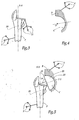
- a generally hemispherical cavity C is dug in the area of the basin B where the implantation of the acetabulum 16 of the prosthesis is planned. 10, as shown on the figure 4 .
- a first solution is to equip the digging cutter cavity with a set of reflective markers similar to the markers 5 or 6, so as to record the progress of this mill in the pelvic bone and thus allow the computer 2, which knows in advance the geometric characteristics of the cutter used, in particular to determine the position of the center O of the milled cavity.
- Another solution, which may be combined with the first, is to feel the cavity once it is dug.
- a third solution is to use a phantom cup equipped with reflective markers similar to markers 5 or 6 and to position this phantom cup at the bottom of the countersunk cavity.
- the computer knows the position in the space of the center O of the cavity C, as well as possibly other geometric characteristics relating to this cavity, in particular its radius.
- a phantom femoral component 22 shown on the figure 5 , being in a form generally similar to the upper end portion of the femoral portion 11 of the prosthesis 10, but with larger dimensions.
- this femoral component 22, hereinafter referred to as "mega-head” comprises a substantially hemispherical head 23 having an axis of symmetry YY.
- the head 23 is integral with an essentially cylindrical neck 24 of axis YY.
- the free end of the neck 24 is provided with securing means at the upper free end of the rasp 20, left in place in the diaphysis of the femur F at the end of the step of grating.
- the head 23 of the mega-head 22 defines an articular surface 25 substantially identical to the outer surface of the acetabulum 16 of the prosthesis 10 to be implanted.
- the head 23 is thus able to be articulated directly into the cavity
- the position in the space of the mega-head 22, in particular of its axis YY, is known to the computer 2 via the sensors 5 since the mega-head is worn. by the handle of the rasp 20 whose position relative to the femur F was determined and stored by the computer during the third time of the intervention.
- the surgeon solicits the hip of the patient so that it occupies successively several configurations considered as extreme, that is to say configurations that the local morphology of the patient imposes on him as natural limits.
- the patient's hip is thus solicited in one or more configurations combining flexion-extension, abduction-adduction and / or internal internal rotations, for example in the tailor configuration.
- Each of these extreme configurations characterizes an articular amplitude specific to the hip of the operated patient that the implantable prosthesis 10 is supposed to be able to reproduce without running the risk of being dislocated.
- the surgeon When the surgeon solicits the hip joint in one of these extreme configurations, he actuates the control pedal 8 and the computer set 2 - sensor 3 physically measures and stores the position of the YY axis of the mega-head 22 relative to the B pelvis bone.
- the different positions thus measured are displayed on the screen 7, in particular in the form of symbolic bars Y 1 , Y 2 ..., Y 6 , the basin B being schematically represented by a parallelepiped B 'and the implantation cavity C being represented by a substantially hemispherical hollow C' corresponding, the graphical representations of these elements B 'and C' being previous measurements of basin B and cavity C.
- the hip joint is dislocated and the mega-head 22 is removed.
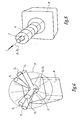
- an acetabular ancillary 30 represented alone on the figure 7 , which comprises a phantom cup 31 fixedly connected to a rigid handling handle 32 equipped with reflective markers 33 similar to the markers 5 or 6.
- the phantom cup 31 is in the form of a hemisphere delimiting a convex articular surface 34 substantially identical to the outer surface of the acetabulum 16 of the prosthesis 10 to be implanted.
- the axis of generation of this phantom cotyle is denoted ZZ and is permanently marked in space by the computer set 2 - sensor 3, the computer knowing in advance the fixed geometric relation between this axis ZZ and the markers 33.
- the phantom cup 31 is manipulated so as to be housed in the milled cavity C so that its axis ZZ substantially passes through the center O of this cavity.
- the computer 2 displays on its screen 7, in superposition of the bars Y 1 to Y 6 , the prosthetic mobility cone P associated with the prosthesis 10 to be implanted, as a function of the position actually occupied by the phantom cup 31 in the cavity C, that is to say according to the position of its axis ZZ.
- the computer 2 in fact knows in advance the structural characteristics of the prosthesis 10, in particular the apex angle of its prosthetic mobility cone, only the position of the axis of revolution of this cone, simulated by the ZZ axis of the phantom cotyle 31, being adjustable by the surgeon.
- the surgeon then visually compares the position of the bars Y 1 to Y 6 representative of the mobility articular maximum of the hip of the patient with the prosthetic mobility cone P envisaged according to the exact position of the phantom cup 31 in the countersunk cavity C. If, as on the figure 6 , the set of bars Y 1 to Y 6 appears, at the level of the display screen 7, inside the cone P, the position of the axis ZZ is considered as acceptable, that is to say say that the prosthesis 10 thus implanted will allow the patient, from the point of view of prosthetic mobility, to limit as much as possible the risk of dislocation of the prosthesis.
- the surgeon moves the phantom cotyle 31 to find a position in which the risk of subsequent dislocations of the prosthesis 10 is strongly limited.
- additional information on the respective angles of the bars Y 1 to Y 6 and the axis ZZ can be provided to the surgeon to allow it to quickly and easily find that position.
- other angles of view of the elements of the figure 6 are advantageously proposed, including the angle at which the cone P appears generally in the form of a circle, the graphical representation of the ZZ axis then being directed perpendicularly to the plane of view.
- the rasp 20 in parallel with or after the determination of the preferred direction of the ZZ axis, it is possible to control this direction by equipping the rasp 20 with a femoral test head (not shown), geometric dimensions substantially identical to the femoral head 15 of the prosthesis 10.
- This test head is then able to be articulated inside the phantom cup 31 which reproduces the internal geometric characteristics of the insert 17 of the prosthesis 10
- the hip joint thus formed is then reduced and then solicited by the surgeon according to various extreme joint configurations, in particular to check that the neck of the test head does not come into contact with the bone material of the pelvis B causing dislocation of the prosthesis.
- this ancillary is equipped with means for locating in space, allowing the computer assembly 2 - sensor 3 to display on the screen 7 the position of its impinging direction I, as shown on the figure 8 on which the impactor is symbolized by a tube I '.
- the surgeon positions the impactor so that the direction I, in the extension of the axis CC of the acetabulum, is substantially aligned with the preferred position Z p - Z p of the axis of the prosthetic mobility cone.
- the computer 2 displays a virtual guide tube G, partially hollowed out, inside which the symbolic representation I 'of the impactor must be placed coaxially to ensure the alignment of the directions I and Z p -Z p .
- a visual report such as a color change or blink, signals alignment to the surgeon.
- the insert 17 is then housed in the implanted acetabulum.
- the device 1 according to the invention thus makes it possible to position the prosthesis 10 optimally to reproduce as much as possible the kinematic capacities of the anatomical hip of the operated patient.
- the eight intraoperative times described above are performed during a surgical procedure proper, that is to say during which the patient is for example under anesthesia.
- the various data recorded during the fitting of the prosthesis 10 can be used to draw up a post-operative check-up and thus make it possible to precisely characterize the joint capacities of the prosthesis in its implantation state in the hip bones. It is also possible to determine the elongation between femur F and pelvis B during surgery. It will be noted, however, that the data acquired are much less numerous than those required for the operation of a biomechanical simulator of the hip to be operated and the corresponding computer means of the device according to the invention are therefore less expensive and less complex to handle.
- the implantation device 1 is also easily applicable to prostheses of different geometries, only the prosthetic mobility characteristics being to be provided to the computer 2 for allow to display the cone P.
- Corresponding sets of strawberries and rasps are provided, and a set of several phantom cups 31 of different sizes and geometries, able to be secured to the same handle 32.
- the use of the cotyloidal ancillary 30 is not essential since the data relating to the prosthetic mobility cone P are known in advance from the computer 2, only the position of the ZZ axis with respect to the cavity C of the pelvis B to be adjusted during surgery to ensure the subsequent operation without dislocation of the prosthesis 10. It is therefore possible that the surgeon uses only virtual representations to adjust the position of this axis ZZ, in displaying the different prosthetic mobility cones which correspond to different positions of the ZZ axis, for example by means of an appropriate computer interface enabling it to modify the position of the virtual axis ZZ and to choose the preferred axis Z p - Z p .
Abstract
Description
La présente invention concerne un dispositif chirurgical d'implantation d'une prothèse totale de hanche.The present invention relates to a surgical device for implantation of a total hip prosthesis.
Une prothèse totale de hanche comporte de façon classique, d'une part, une partie fémorale constituée d'une tige à une extrémité de laquelle est fixée une tête fémorale délimitant une surface articulaire convexe globalement sphérique et, d'autre part, une partie cotyloïdienne à fixer à l'os du bassin, comportant par exemple une cupule métallique cotyloïdienne en forme de demi-sphère, à l'intérieur de laquelle est logé un insert en matière plastique ou en céramique dans lequel vient s'articuler la tête fémorale.A total hip prosthesis conventionally comprises, on the one hand, a femoral portion consisting of a rod at one end of which is fixed a femoral head delimiting a globally spherical convex articular surface and, on the other hand, an acetabular part. to be fixed to the pelvic bone, comprising for example an acetabular acetabular cup in the shape of a half-sphere, inside which is housed a plastic or ceramic insert in which the femoral head is articulated.
Lors de la pose d'une telle prothèse totale de hanche, le chirurgien implante d'une part la tige fémorale à l'intérieur d'une cavité creusée longitudinalement dans l'os du fémur et, d'autre part, la partie cotyloïdienne de la prothèse dans une cavité globalement hémisphérique creusée dans l'os du bassin. La direction d'implantation de la tige fémorale dans l'os du fémur est globalement imposée par la forme allongée de l'os du fémur alors que le chirurgien dispose d'une plus grande liberté pour choisir la position d'implantation de la partie cotyloïdienne dans la cavité creusée dans l'os du bassin. Le choix de cette position influe directement sur la position de l'axe de révolution du cône de mobilité théorique de la prothèse implantée, cet axe de révolution correspondant en fait à l'axe de révolution de la cupule hémisphérique solidarisée à l'os du bassin.During the installation of such a total hip prosthesis, the surgeon implants on the one hand the femoral stem inside a cavity hollowed longitudinally in the femur bone and, on the other hand, the cotyloid part of the prosthesis in a globally hemispherical cavity carved into the pelvic bone. The direction of implantation of the femoral stem in the femur bone is generally imposed by the elongated shape of the femur bone while the surgeon has greater freedom to choose the implantation position of the acetabulum. in the cavity dug in the pelvic bone. The choice of this position directly influences the position of the axis of revolution of the theoretical mobility cone of the implanted prosthesis, this axis of revolution corresponding in fact to the axis of revolution of the hemispherical cup secured to the pelvic bone. .
On a remarqué que le positionnement du cotyle au niveau de la zone d'implantation du bassin a des conséquences sur le comportement mécanique de la prothèse implantée. Plus précisément, lorsque la prothèse est articulée selon des mouvements d'amplitude extrême, notamment selon des mouvements combinant des déplacements élémentaires de la hanche en flexion-extension, en abduction-adduction et/ou en rotation interne-rotation externe, il arrive qu'elle soit sollicitée en dehors de son cône de mobilité prothétique, provoquant alors un contact d'appui entre le col fémoral de la prothèse et le bord du cotyle. Dans ces conditions, il arrive que la prothèse se luxe.It has been observed that the positioning of the acetabulum at the level of the implantation zone of the pelvis has consequences on the mechanical behavior of the implanted prosthesis. More specifically, when the prosthesis is articulated according to movements of extreme amplitude, in particular according to movements combining displacements elementary hip flexion-extension, abduction-adduction and / or internal rotation-external rotation, it may be solicited outside its prosthetic mobility cone, causing a contact contact between the femoral neck of the prosthesis and the edge of the acetabulum. In these conditions, it happens that the prosthesis is luxury.
Le but de la présente invention est de proposer un dispositif chirurgical qui assiste de manière plus simple, plus rapide et plus économique le chirurgien lors de la chirurgie d'implantation d'une prothèse totale de hanche en vue de limiter les risques de luxations ultérieures de la prothèse en s'adaptant au mieux à l'anatomie de chaque patient traité.The object of the present invention is to provide a surgical device that assists the surgeon more easily, more quickly and economically during the surgery to implant a total hip prosthesis to limit the risk of subsequent dislocations of the prosthesis by best adapting to the anatomy of each treated patient.
A cet effet, l'invention a pour objet un dispositif chirurgical d'implantation d'une prothèse totale de hanche en accord avec la revendication 1.For this purpose, the subject of the invention is a surgical device for implanting a total hip prosthesis according to claim 1.
En utilisant le dispositif selon l'invention, le chirurgien peut, au cours de la chirurgie proprement dite, comparer le cône de mobilité prothétique associé à la prothèse à implanter avec les différentes positions mesurées de la direction prothétique fémorale considérée, ces positions correspondant de préférence à des configurations articulaires extrêmes de la hanche du patient opéré, à savoir des configurations articulaires combinant des mouvements de flexion/extension, d'abduction/adduction et/ou de rotation interne/externe, telles que par exemple la configuration en tailleur qui combine des mouvements de flexion, d'abduction et de rotation externe. Le chirurgien choisit alors, durant l'intervention chirurgicale de pose de la prothèse, une direction préférentielle pour implanter le cotyle de la prothèse, permettant la sollicitation ultérieure de la prothèse jusque dans ces configurations articulaires extrêmes sans risquer sa luxation. Autrement dit, le dispositif chirurgical selon l'invention permet au chirurgien de déterminer cette direction d'implantation préférentielle, ou plusieurs de ces directions préférentielles, que le chirurgien va ensuite respecter à la fin de l'intervention chirurgicale pour implanter le cotyle de la prothèse.Using the device according to the invention, the surgeon can, during the actual surgery, compare the prosthetic mobility cone associated with the prosthesis to be implanted with the different measured positions of the femoral prosthetic direction considered, these positions preferably corresponding to extreme joint configurations of the hip of the operated patient, namely joint configurations combining flexion / extension, abduction / adduction and / or internal / external rotation movements, such as for example the tailor-made configuration which combines bending, abduction and external rotation movements. The surgeon then chooses, during the prosthesis-fitting surgical procedure, a preferential direction for implanting the acetabulum of the prosthesis, allowing the prosthesis to be later urged into these extreme joint configurations without risking dislocation. In other words, the surgical device according to the invention allows the surgeon to determine this preferred implantation direction, or more of these preferential directions, which the surgeon will then respect at the end of the surgical procedure to implant the acetabulum of the prosthesis.
D'autres caractéristiques de ce dispositif, prises isolément ou selon toutes les combinaisons techniquement possibles, sont énoncées aux revendications dépendantes 2 à 10.Other features of this device, taken in isolation or in any technically possible combination, are set forth in
Avec le dispositiv selon l'invention on peut effectuer une méthode chirurgicale d'implantation d'une prothèse totale de hanche, dans laquelle, en peropératoire, successivement :
- on repère dans l'espace l'os du fémur et l'os du bassin d'un patient à traiter,
- on mesure et on mémorise plusieurs positions d'une direction prothétique fémorale donnée par rapport à une cavité du bassin,
- on compare ces positions mesurées avec le cône de mobilité de la prothèse à implanter, la position de l'axe de révolution de ce cône étant ajustée par rapport à la cavité au cours de l'intervention chirurgicale,
- on détermine au moins une position préférentielle de cet axe de révolution, et
- on impacte une partie cotyloïdienne de la prothèse dans la cavité du bassin suivant ladite position préférentielle.
- the bone of the femur and the pelvic bone of a patient to be treated are located in space,
- several positions of a given femoral prosthetic direction with respect to a cavity of the pelvis are measured and memorized,
- these measured positions are compared with the mobility cone of the prosthesis to be implanted, the position of the axis of revolution of this cone being adjusted relative to the cavity during the surgical procedure,
- at least one preferential position of this axis of revolution is determined, and
- an acetabulum portion of the prosthesis is impacted in the pelvic cavity following said preferred position.
L'invention sera mieux comprise à la lecture de la description qui va suivre, donnée uniquement à titre d'exemple et faite en se référant aux dessins sur lesquels :
- la
figure 1 est_ une vue schématique d'une partie d'un dispositif chirurgical selon l'invention, appliqué à la hanche d'un patient à opérer ; - la
figure 2 est une vue éclatée en perspective d'une prothèse totale de hanche à implanter au moyen du dispositif de lafigure 1 ; - la
figure 3 est une vue schématique en élévation d'une autre partie du dispositif selon l'invention, en cours d'utilisation sur le fémur de la hanche du patient ; - la
figure 4 est une vue en coupe d'une cavité cotyloïdienne creusée dans le bassin de la hanche du patient, au moyen du dispositif selon l'invention ; - la
figure 5 est une vue schématique illustrant la mise en place, à l'intérieur de la cavité de lafigure 4 , d'un composant fémoral fantôme du dispositif selon l'invention ; - la
figure 6 représente une vue schématique en perspective affichée à l'intention du chirurgien par le dispositif selon l'invention ; - la
figure 7 est une vue en perspective d'un composant cotyloïdien fantôme du dispositif selon l'invention ; et - la
figure 8 représente une autre vue schématique en perspective affichée à l'intention du chirurgien par le dispositif selon l'invention.
- the
figure 1 is a schematic view of a portion of a surgical device according to the invention, applied to the hip of a patient to operate; - the
figure 2 is an exploded perspective view of a total hip prosthesis implanted by means of the device of thefigure 1 ; - the
figure 3 is a schematic view in elevation of another part of the device according to the invention, in use on the femur of the hip of the patient; - the
figure 4 is a sectional view of an acetabular cavity dug in the pelvis of the hip of the patient, by means of the device according to the invention; - the
figure 5 is a schematic view illustrating the placement, inside the cavity of thefigure 4 , a phantom femoral component of the device according to the invention; - the
figure 6 represents a schematic view in perspective displayed for the surgeon by the device according to the invention; - the
figure 7 is a perspective view of a phantom cotyloid component of the device according to the invention; and - the
figure 8 represents another schematic view in perspective displayed for the surgeon by the device according to the invention.
Le dispositif chirurgical 1 de la
Pour permettre à l'ordinateur 2 de repérer dans l'espace les os du fémur F et du bassin B, le dispositif 1 comporte des groupes respectifs de marqueurs 5 et 6 qui renvoient, de façon passive, le rayonnement infra-rouge en direction du capteur 3. Chaque groupe de marqueurs 5 ou 6 forme un système de marquage tri-dimensionnel permettant à l'ensemble ordinateur 2 - capteur 3 de suivre dans l'espace les déplacements respectifs du fémur et du bassin. L'utilisation de tels marqueurs étant bien connue dans le domaine de l'orthopédie, ils ne seront donc pas décrits ici plus avant.In order to allow the
Chaque groupe de marqueurs 5 ou 6 est fixé à l'os du fémur ou du bassin au moyen d'une ou de plusieurs broches rigides. Comme on le comprendra après, ces broches sont placées de manière à laisser les marqueurs visibles pour le capteur 3 aussi bien lorsque l'articulation de la hanche est réduite (comme sur la
L'ordinateur 2 du dispositif 1 est également associé à un ou plusieurs écrans 7 à même d'afficher des informations utiles au chirurgien, notamment les informations relatives à la position des os F et B et d'autres données décrites plus loin, de préférence sous forme de représentations graphiques tri-dimensionnelles comme détaillé ci-après.The
Le dispositif 1 comporte également des moyens de commande 8 par exemple sous forme d'une pédale à même d'être actionnée par le pied du chirurgien.The device 1 also comprises control means 8 for example in the form of a pedal capable of being actuated by the foot of the surgeon.
Le dispositif chirurgical 1 comporte en outre d'autres composants qui vont être détaillés ci-après lors de la description d'un exemple détaillé d'utilisation du dispositif en vue de l'implantation d'une prothèse totale de hanche 10 représentée seule sur la
La partie cotyloïdienne 12 comporte un cotyle 16 sous forme d'une cupule métallique sensiblement hémisphérique destinée à être solidarisée à l'os du bassin B. L'axe de révolution de la surface interne concave du cotyle est noté C-C. A l'intérieur de cette cupule est prévu d'être logé de manière fixe un insert 17 également hémisphérique d'axe de révolution C-C, constitué d'une matière plastique ou céramique. La surface intérieure de l'insert 17 est conformée de manière sensiblement complémentaire à la surface extérieure de la tête fémorale 15, de manière à ce que cette dernière s'articule à la manière d'une rotule par rapport à l'ensemble cotyloïdien 12.The
La prothèse 10 décrite ci-dessus n'est donnée qu'à titre d'exemple et d'autres prothèses, de géométries et/ou de natures différentes, peuvent être implantées au moyen du dispositif 1, suivant la méthode chirurgicale d'implantation décrite ci-après. En particulier, l'invention s'applique à la pose de prothèses dont la partie cotyloïdienne est constituée d'une seule cupule à cimenter à l'os du bassin et dans laquelle est articulée directement la tête fémorale prothétique ou dont la partie cotyloïdienne comporte, en plus d'une première cupule métallique à fixer au bassin, une seconde cupule montée dans cette première cupule de façon articulée (on parle alors d'un ensemble cotyloïdien à double mobilité). Dans tous les cas, la partie cotyloïdienne de la prothèse délimite un axe de révolution pour la surface interne concave de la cupule à fixer au bassin, analogue à l'axe C-C.The
Dans un premier temps, le chirurgien incise le patient et recueille un certain nombre de données relatives à la géométrie anatomique des os du fémur F et du bassin B. A cet effet, différents moyens d'acquisition de ces données sont envisageables. A titre d'exemple, le chirurgien utilise un palpeur 9 repéré par l'ensemble ordinateur 2 - capteur 3 et préalablement étalonné. Ce palpeur est amené sur des lieux remarquables des os et, à chacune de ces mises en place, le chirurgien actionne la pédale de commande 8 de manière à ce que l'ordinateur 2 enregistre la position du palpeur et par là en déduise les caractéristiques anatomiques du fémur F et du bassin B. A partir de ces données et du suivi des marqueurs 5 et 6, l'ordinateur 2 est capable de repérer dans l'espace les os du fémur et du bassin.Firstly, the surgeon incises the patient and collects a certain amount of data relating to the anatomical geometry of the bones of femur F and pelvis B. For this purpose, various means of acquiring this data are possible. For example, the surgeon uses a
Durant cette étape d'acquisition de données, l'articulation de la hanche est successivement luxée et réduite, les marqueurs réfléchissants 5 et 6 restant visibles pour le capteur 3.During this data acquisition step, the hip joint is successively dislocated and reduced, the
Dans un deuxième temps, la tête anatomique du fémur F est, si nécessaire, réséquée.In a second step, the anatomical head of the femur F is, if necessary, resected.
Dans un troisième temps, une cavité, destinée à recevoir ultérieurement la tige fémorale 13 de la prothèse 10, est creusée dans la diaphyse du fémur F. A cet effet, le chirurgien utilise d'abord une broche rigide non représentée qu'il introduit dans le canal médullaire anatomique du fémur et qu'il repère dans l'espace au moyen de l'ensemble ordinateur 2 - capteur 3 en venant par exemple palper une extrémité de cette broche portant un relief prédéterminé. Le chirurgien positionne alors la broche ainsi repérée de manière à ce qu'elle s'étende suivant une direction diaphysaire X-X destinée à constituer l'axe d'implantation de la partie fémorale 11 de la prothèse. Cette direction diaphysaire X-X est par exemple arbitrairement choisie par le chirurgien, en fonction de la forme et de l'état du fémur. Lorsque cette broche est positionnée convenablement, le chirurgien actionne la pédale de commande 8 et l'ordinateur 2 mémorise la position de l'axe X-X, notamment par rapport au fémur F.In a third step, a cavity, intended to subsequently receive the
Après avoir retiré la broche, le chirurgien utilise ensuite une râpe fémorale 20 représentée en pointillés sur la
A la fin de l'étape de râpage, l'axe X-X d'implantation de la partie fémorale 11 est remplacé par l'axe de râpage effectivement réalisé si celui-ci s'est écarté de l'axe diaphysaire prévu par la broche.At the end of the grating step, the axis X-X implantation of the
Dans un quatrième temps, indépendant des deuxième et troisième temps décrits ci-dessus et qui peut donc être interverti avec ces derniers, une cavité C globalement hémisphérique est creusée dans la zone du bassin B où est prévue l'implantation du cotyle 16 de la prothèse 10, comme représenté sur la
Dans tous les cas, à la fin de cette étape, l'ordinateur connaît la position dans l'espace du centre O de la cavité C, ainsi qu'éventuellement d'autres caractéristiques géométriques relatives à cette cavité, notamment son rayon.In any case, at the end of this step, the computer knows the position in the space of the center O of the cavity C, as well as possibly other geometric characteristics relating to this cavity, in particular its radius.
Dans un cinquième temps, on mesure et on mémorise plusieurs configurations d'articulation de la hanche réduite du patient. A cet effet est utilisé un composant fémoral fantôme 22, représenté sur la
La tête 23 de la méga-tête 22 délimite une surface articulaire 25 sensiblement identique à la surface externe du cotyle 16 de la prothèse 10 à implanter. La tête 23 est ainsi à même d'être articulée directement dans la cavité fraisée C de l'os du bassin B. La position dans l'espace de la méga-tête 22, notamment de son axe Y-Y, est connue de l'ordinateur 2 par l'intermédiaire des capteurs 5 puisque la méga-tête est porté par le manche de la râpe 20 dont la position par rapport au fémur F a été déterminée et mémorisée par l'ordinateur lors du troisième temps de l'intervention.The
Alors que la méga-tête 22 est articulée à l'intérieur de la cavité C, le chirurgien sollicite la hanche du patient de manière à ce qu'elle occupe successivement plusieurs configurations considérées comme extrêmes, c'est-à-dire des configurations que la morphologie locale du patient lui impose comme limites naturelles. La hanche du patient est ainsi sollicitée dans une ou plusieurs configurations combinant des mouvements de flexion-extension, abduction-adduction et/ou rotations interneexterne, par exemple dans la configuration en tailleur. Chacune de ces configurations extrêmes caractérise une amplitude articulaire propre à la hanche du patient opéré que la prothèse 10 à implanter est censée par la suite pouvoir reproduire sans courir le risque d'être luxée.While the mega-head 22 is articulated inside the cavity C, the surgeon solicits the hip of the patient so that it occupies successively several configurations considered as extreme, that is to say configurations that the local morphology of the patient imposes on him as natural limits. The patient's hip is thus solicited in one or more configurations combining flexion-extension, abduction-adduction and / or internal internal rotations, for example in the tailor configuration. Each of these extreme configurations characterizes an articular amplitude specific to the hip of the operated patient that the
Lorsque le chirurgien sollicite l'articulation de la hanche dans une de ces configurations extrêmes, il actionne la pédale de commande 8 et l'ensemble ordinateur 2 - capteur 3 mesure physiquement et mémorise la position de l'axe Y-Y de la méga-tête 22 par rapport à l'os du bassin B. Comme représenté sur la
Une fois ces mesures effectuées, l'articulation de la hanche est luxée et la méga-tête 22 est retirée.Once these measurements are made, the hip joint is dislocated and the mega-head 22 is removed.
Dans un sixième temps, le chirurgien utilise un ancillaire cotyloïdien 30 représenté seul sur la
Au moyen du manche 32, le cotyle fantôme 31 est manipulé de façon à être logé dans la cavité fraisée C de telle sorte que son axe Z-Z passe sensiblement par le centre O de cette cavité. Comme représenté sur la
Le chirurgien compare alors visuellement la position des barres Y1 à Y6 représentatives de la mobilité articulaire maximale de la hanche du patient avec le cône de mobilité prothétique P envisagé selon la position exacte du cotyle fantôme 31 dans la cavité fraisée C. Si, comme sur la
Lorsque le chirurgien a trouvé une position satisfaisante pour le cotyle fantôme 31, il enregistre la position de son axe Z-Z au moyen de l'ordinateur 2, cette direction, notée Zp-Zp sur la
En option, en parallèle de ou après la détermination de la direction préférentielle de l'axe Z-Z, il est possible de contrôler cette direction en équipant la râpe 20 d'une tête fémorale d'essai non représentée, de dimensions géométriques sensiblement identiques à la tête fémorale 15 de la prothèse 10. Cette tête d'essai est alors à même d'être articulée à l'intérieur du cotyle fantôme 31 qui reproduit les caractéristiques géométriques internes de l'insert 17 de la prothèse 10. L'articulation de hanche ainsi formée est alors réduite puis sollicitée par le chirurgien selon différentes configurations articulaires extrêmes, afin de vérifier notamment que le col de la tête d'essai n'entre pas en contact avec la matière osseuse du bassin B en provoquant la luxation de la prothèse.Optionally, in parallel with or after the determination of the preferred direction of the ZZ axis, it is possible to control this direction by equipping the
Après avoir retiré le cotyle fantôme 31, le chirurgien utilise ensuite dans un septième temps un impacteur non représenté pour mettre en place de manière définitive le cotyle 16 de la prothèse 10. Pour permettre d'impacter ce cotyle de sorte que son axe C-C coïncide avec la direction préférentielle Zp-Zp, cet ancillaire est équipé de moyens de repérage dans l'espace, permettant à l'ensemble ordinateur 2 - capteur 3 d'afficher sur l'écran 7 la position de sa direction d'impaction I, comme représenté sur la
L'insert 17 est ensuite logé dans le cotyle implanté.The
Une fois l'impaction réalisée, tous les composants fémoraux du dispositif 1 sont retirés et la partie fémorale 11 de la prothèse 10 est, dans un huitième temps, implantée de manière à ce que l'axe A-A de sa tige 13 soit disposé de manière sensiblement confondue avec l'axe d'implantation fémorale X-X. Dans la mesure où la râpe 20 a ménagé une cavité diaphysaire sensiblement complémentaire de cette tige, il est suffisant d'impacter de manière classique la tige 13 dans le fémur F pour obtenir la coïncidence des axes A-A et X-X.Once the impaction has been performed, all the femoral components of the device 1 are removed and the femoral part is removed. 11 of the
Le dispositif 1 selon l'invention permet ainsi de positionner la prothèse 10 de façon optimale pour reproduire autant que possible les capacités cinématiques de la hanche anatomique du patient opéré. On notera que les huit temps peropératoires décrits ci-dessus sont effectués au cours d'une intervention chirurgicale proprement dite, c'est-à-dire durant laquelle le patient est par exemple sous anesthésie.The device 1 according to the invention thus makes it possible to position the
De plus, les différentes données enregistrées durant la pose de la prothèse 10 peuvent être utilisées pour dresser un bilan post-opératoire et permettre ainsi de caractériser avec précision les capacités articulaires de la prothèse dans son état d'implantation dans les os de la hanche. Il est également possible de déterminer l'allongement entre le fémur F et le bassin B durant l'intervention chirurgicale. On remarquera cependant que les données acquises sont nettement moins nombreuses que celles nécessaires pour le fonctionnement d'un simulateur biomécanique de la hanche à opérer et les moyens informatiques correspondants du dispositif selon l'invention sont donc moins onéreux et moins complexes à manipuler.In addition, the various data recorded during the fitting of the
Comme indiqué plus haut, le dispositif d'implantation 1 est en outre facilement applicable à des prothèses de différentes géométries, seules les caractéristiques de mobilité prothétique étant à fournir à l'ordinateur 2 pour permettre d'afficher le cône P. Des jeux correspondants de fraises et de râpes sont prévus, ainsi qu'un jeu de plusieurs cotyles fantômes 31 de tailles et de géométries différentes, à même d'être solidarisés à un même manche 32.As indicated above, the implantation device 1 is also easily applicable to prostheses of different geometries, only the prosthetic mobility characteristics being to be provided to the
Divers aménagements et variantes au dispositif d'implantation 1 décrit ci-dessus sont en outre envisageables.Various arrangements and variants of the implantation device 1 described above are furthermore possible.
En particulier, l'utilisation de l'ancillaire cotyloïdien 30 n'est pas indispensable puisque les données relatives au cône de mobilité prothétique P sont connues à l'avance de l'ordinateur 2, seule la position de l'axe Z-Z par rapport à la cavité C du bassin B étant à ajuster en cours d'intervention pour garantir le fonctionnement ultérieur sans luxation de la prothèse 10. Il est donc envisageable que le chirurgien n'utilise que des représentations virtuelles pour ajuster la position de cet axe Z-Z, en affichant les différents cônes de mobilité prothétique qui correspondent à différentes positions de l'axe Z-Z, par exemple au moyen d'une interface informatique appropriée lui permettant de modifier la position de l'axe virtuel Z-Z et de choisir l'axe préférentiel Zp-Zp.In particular, the use of the cotyloidal ancillary 30 is not essential since the data relating to the prosthetic mobility cone P are known in advance from the
D'autres variantes sont énumérées ci-dessous :
- pour supporter la méga-
tête 22, le manche de râpe 20 peut être remplacé par une broche fémorale ou par la tige fémorale de la prothèse à implanter, la méga-tête pouvant alors éventuellement être venue de matière avec son support fémoral ; - la méga-
tête 22 décrite ci-dessus peut être remplacée par un composant fémoral fantôme constitué d'une tête de dimensions sensiblement identiques à celles de la tête fémorale prothétique et d'une calotte hémisphérique articulée sur cette tête et de dimensions sensiblement identiques à celles de la partie cotyloïdienne prothétique ; - les moyens de repérage des os du fémur F et du bassin B ne sont pas limités à des marqueurs réfléchissant l'infra-rouge, des marqueurs sensibles aux ultra-sons ou aux champs électromagnétiques étant par exemple utilisables ;
- la cavité C peut être fraisé après avoir déterminé la direction préférentielle Zp-Zp ; on utilise dans ce cas la cavité anatomique de la hanche comme logement articulaire de la méga-
tête 22 pour mesurer les différentes configurations articulaires extrêmes ; - d'autres moyens qu'un écran d'affichage sont envisageables pour communiquer au chirurgien un retour d'informations sur la comparaison entre les mesures des configurations articulaires extrêmes et le cône de mobilité prothétique ; des indications sonores ou tactiles peuvent ainsi faire comprendre au chirurgien l'état de cette comparaison et le guider dans la détermination de la direction préférentielle Zp-Zp ; et/ou
- la détermination de la direction préférentielle Zp-Zp peut être intégralement assurée par un logiciel approprié équipant l'ordinateur 2, à partir de la comparaison du cône P et des mesures des différentes configurations articulaires extrêmes mesurées en peropératoire, et ce par calcul et extrapolation.
- to support the mega-head 22, the rasp handle 20 can be replaced by a femoral pin or the femoral stem of the prosthesis to be implanted, the mega-head can then possibly be made of material with its femoral support;
- the mega-head 22 described above may be replaced by a phantom femoral component consisting of a head of substantially identical dimensions to those of the prosthetic femoral head and a hemispherical cap articulated on this head and of dimensions substantially identical to those of the prosthetic cotyloid part;
- the means for locating the femur B and the pelvis B are not limited to infra-red reflective markers, markers sensitive to ultrasound or electromagnetic fields for example being usable;
- the cavity C can be milled after determining the preferred direction Zp-Zp; in this case, the anatomical cavity of the hip is used as the articular seat of the mega-head 22 to measure the various extreme joint configurations;
- other means than a display screen are conceivable to communicate to the surgeon feedback on the comparison between the measurements of the extreme joint configurations and the prosthetic mobility cone; audible or tactile indications can thus make the surgeon understand the state of this comparison and guide it in determining the preferential direction Zp-Zp; and or
- the determination of the preferential direction Zp-Zp can be entirely ensured by appropriate software equipping the
computer 2, from the comparison of the cone P and the measurements of the various extreme joint configurations measured intraoperatively, and this by calculation and extrapolation.
Claims (10)
- Surgical device for implanting a total hip prosthesis (10) having a cone of mobility (P) with an axis of revolution (Z-Z), this device comprising measuring means (2, 3, 22) for per-operatively measuring a plurality of positions of a given femoral prosthetic direction (Y-Y) and providing means (2, 3, 30) for per-operatively providing the position in space of the axis of revolution (Z-Z) of the cone of mobility (P), characterised by means (2) for memorizing the said positions of the femoral prosthetic direction (Y-Y), and by means (2) for per-operatively comparing of the said positions with the cone of mobility (P) of the prosthesis (10) to be implanted, so as to adjust in space the position of the axis of revolution (Z-Z) of this cone during the implantation of the prosthesis, so that said positions of the femoral prosthetic direction (Y-Y) are located within the cone (P).
- The device of Claim 1, characterized in that it comprises means (7) for communicating to the surgeon the comparison between the positions of the femoral prosthetic direction (Y-Y) and the cone (P) of mobility of the prosthesis.
- The device of Claim 2, characterized in that the communication means comprise a means for displaying (7) symbolic representations (Y1, ... Y6, P) of the positions of the femoral prosthetic direction (Y-Y) and of the position of the cone of mobility of the prosthesis.
- The device of any one of the preceding Claims, characterized in that it comprises means (2, 8) for selection by the surgeon or for calculation and memorization of at least one preferential position (Zp-Zp) of the axis (Z-Z) of the cone (P) of mobility of the prosthesis.
- The device of Claim 4, characterized in that it further comprises, on the one hand, an impactor for definitively positioning the acetabulum (16) of the prosthesis (10) in the zone of implantation (C) of the pelvis (B), equipped with means for locating in space and, on the other hand, means (2) for comparing the direction of impaction (I) of this impactor with the preferential position (Zp-Zp).
- The device of any one of the preceding Claims, characterized in that the measuring means comprise a phantom femoral component (22) defining the femoral prosthetic direction (Y-Y), so that the said positions of the femoral prosthetic direction (Y-Y) to be compared with the prosthetic cone of mobility (P) correspond to positions of this femoral component in space, especially with respect to a zone (C) of the pelvis (B) where the implantation of an acetabulum (16) of the prosthesis is provided.
- The device of Claim 6, characterized in that it comprises means for determining the centre (O) of an osseous cavity (C) of the pelvis (B), constituting the zone of implantation of the pelvis and adapted to receive the phantom femoral component (22) when the different positions of this component are measured.
- The device of one of Claims 6 or 7, characterized in that it comprises a support (20) for the phantom femoral component (22), adapted to be fixedly connected to the femur (F) and to bear means (21) for locating in space.
- The device of any one of Claims 6 to 8, characterized in that the phantom femoral component (22) defines an articular surface (25) adapted to be directly articulated on the zone of implantation (C) of the pelvis (B) and substantially identical to the outer surface of the acetabulum (16) of the prosthesis (10) to be implanted.
- The device of any one of the preceding Claims, characterized in that the providing means comprise a phantom acetabulum (31) reproducing the axis (Z-Z) of the cone (P) of mobility of the prosthesis and equipped with a means (32) for manual manipulation in space, especially with respect to the zone of implantation (C) of the pelvis (B), provided with means (33) for locating in space.
Applications Claiming Priority (2)
| Application Number | Priority Date | Filing Date | Title |
|---|---|---|---|
| FR0401281 | 2004-02-10 | ||
| FR0401281A FR2865928B1 (en) | 2004-02-10 | 2004-02-10 | SURGICAL DEVICE FOR IMPLANTATION OF A TOTAL HIP PROSTHESIS |
Publications (2)
| Publication Number | Publication Date |
|---|---|
| EP1563810A1 EP1563810A1 (en) | 2005-08-17 |
| EP1563810B1 true EP1563810B1 (en) | 2010-03-31 |
Family
ID=34685000
Family Applications (1)
| Application Number | Title | Priority Date | Filing Date |
|---|---|---|---|
| EP05356029A Not-in-force EP1563810B1 (en) | 2004-02-10 | 2005-02-09 | Surgical apparatus for implanting a total hip prosthesis |
Country Status (6)
| Country | Link |
|---|---|
| US (1) | US7927338B2 (en) |
| EP (1) | EP1563810B1 (en) |
| JP (1) | JP4981257B2 (en) |
| AT (1) | ATE462384T1 (en) |
| DE (1) | DE602005020204D1 (en) |
| FR (1) | FR2865928B1 (en) |
Cited By (13)
| Publication number | Priority date | Publication date | Assignee | Title |
|---|---|---|---|---|
| WO2012080840A1 (en) * | 2010-12-17 | 2012-06-21 | Avenir Medical Inc. | Method and system for aligning a prosthesis during surgery |
| US8588892B2 (en) | 2008-12-02 | 2013-11-19 | Avenir Medical Inc. | Method and system for aligning a prosthesis during surgery using active sensors |
| US8623023B2 (en) | 2009-04-27 | 2014-01-07 | Smith & Nephew, Inc. | Targeting an orthopaedic implant landmark |
| US8784425B2 (en) | 2007-02-28 | 2014-07-22 | Smith & Nephew, Inc. | Systems and methods for identifying landmarks on orthopedic implants |
| US8814868B2 (en) | 2007-02-28 | 2014-08-26 | Smith & Nephew, Inc. | Instrumented orthopaedic implant for identifying a landmark |
| US8890511B2 (en) | 2011-01-25 | 2014-11-18 | Smith & Nephew, Inc. | Targeting operation sites |
| US8945147B2 (en) | 2009-04-27 | 2015-02-03 | Smith & Nephew, Inc. | System and method for identifying a landmark |
| US9168153B2 (en) | 2011-06-16 | 2015-10-27 | Smith & Nephew, Inc. | Surgical alignment using references |
| US9220514B2 (en) | 2008-02-28 | 2015-12-29 | Smith & Nephew, Inc. | System and method for identifying a landmark |
| US9247998B2 (en) | 2013-03-15 | 2016-02-02 | Intellijoint Surgical Inc. | System and method for intra-operative leg position measurement |
| US9314188B2 (en) | 2012-04-12 | 2016-04-19 | Intellijoint Surgical Inc. | Computer-assisted joint replacement surgery and navigation systems |
| US9526441B2 (en) | 2011-05-06 | 2016-12-27 | Smith & Nephew, Inc. | Targeting landmarks of orthopaedic devices |
| US9539037B2 (en) | 2010-06-03 | 2017-01-10 | Smith & Nephew, Inc. | Orthopaedic implants |
Families Citing this family (142)
| Publication number | Priority date | Publication date | Assignee | Title |
|---|---|---|---|---|
| FR2768613B1 (en) * | 1997-09-23 | 1999-12-17 | Tornier Sa | KNEE PROSTHESIS WITH ROTATABLE PLATFORM |
| FR2797178B1 (en) * | 1999-08-05 | 2002-02-22 | Tornier Sa | MALLEOLAR IMPLANT FOR PARTIAL OR TOTAL ANKLE PROSTHESIS AND ANCILLARY MATERIAL FOR PLACING SUCH AN IMPLANT |
| FR2826860B1 (en) * | 2001-07-09 | 2004-03-05 | Tornier Sa | ANCILLARY OF POSITION OF A CUBITAL COMPONENT AND / OR A RADIAL COMPONENT OF ELBOW PROSTHESIS |
| FR2826859B1 (en) * | 2001-07-09 | 2003-09-19 | Tornier Sa | ANCILLARY OF LAYING OF A HUMERAL COMPONENT OF ELBOW PROSTHESIS |
| FR2827500B1 (en) * | 2001-07-17 | 2004-04-02 | Tornier Sa | PLATE OF OSTEOSYNTHESIS OF THE UPPER END OF THE HUMERUS |
| US11202676B2 (en) | 2002-03-06 | 2021-12-21 | Mako Surgical Corp. | Neural monitor-based dynamic haptics |
| US8010180B2 (en) | 2002-03-06 | 2011-08-30 | Mako Surgical Corp. | Haptic guidance system and method |
| US8996169B2 (en) | 2011-12-29 | 2015-03-31 | Mako Surgical Corp. | Neural monitor-based dynamic haptics |
| WO2003077101A2 (en) | 2002-03-06 | 2003-09-18 | Z-Kat, Inc. | System and method for using a haptic device in combination with a computer-assisted surgery system |
| FR2848183B1 (en) * | 2002-12-10 | 2006-01-27 | Tornier Sa | STERILE CONDITIONING METHOD OF A POLYETHYLENE PROTHETIC IMPLANT |
| FR2850010B1 (en) * | 2003-01-17 | 2005-12-02 | Tornier Sa | ANCILLARY FOR THE INSTALLATION OF A PROTHETIC COTYL FOR A HIP PROSTHESIS |
| US7887544B2 (en) | 2003-03-10 | 2011-02-15 | Tornier Sas | Ancillary tool for positioning a glenoid implant |
| FR2854792B1 (en) * | 2003-05-12 | 2005-09-09 | Tornier Sa | GAME OF PROTHETIC ELEMENTS FOR A TIBIAL PROTHETIC SET |
| FR2855397B1 (en) | 2003-05-28 | 2005-07-15 | Tornier Sa | ELBOW PROSTHESIS |
| US8303665B2 (en) | 2004-06-15 | 2012-11-06 | Tornier Sas | Glenoidal component, set of such components and shoulder prosthesis incorporating such a glenoidal component |
| EP1607069B1 (en) | 2004-06-15 | 2009-12-23 | Tornier | Inverse-type total shoulder prosthesis |
| FR2872025B1 (en) * | 2004-06-28 | 2006-08-25 | Tornier Sas | PROSTHESIS OF SHOULDER OR HIP |
| FR2881340B1 (en) * | 2005-02-01 | 2008-01-11 | Tornier Sas | HUMERAL NUTS |
| CN101155557B (en) * | 2005-02-02 | 2012-11-28 | 奥瑟Hf公司 | Sensing systems and methods for monitoring gait dynamics |
| FR2884408B1 (en) * | 2005-04-13 | 2007-05-25 | Tornier Sas | SURGICAL DEVICE FOR IMPLANTATION OF A PARTIAL OR TOTAL KNEE PROSTHESIS |
| FR2884407B1 (en) * | 2005-04-13 | 2007-05-25 | Tornier Sas | SURGICAL DEVICE FOR IMPLANTATION OF A PARTIAL OR TOTAL KNEE PROSTHESIS |
| US7468077B2 (en) * | 2005-08-02 | 2008-12-23 | Tornier Sas | Patellar retractor and method of surgical procedure on knee |
| FR2896404B1 (en) * | 2006-01-24 | 2008-02-29 | Tornier Sas | SURGICAL INSTRUMENTATION ASSEMBLY FOR POSTING AN ANKLE PROSTHESIS |
| FR2896684B1 (en) * | 2006-02-01 | 2008-09-26 | Tornier Soc Par Actions Simplifiee | TIBIAL IMPLANT WITH OFFSET SHAFT |
| US8608749B2 (en) | 2006-02-27 | 2013-12-17 | Biomet Manufacturing, Llc | Patient-specific acetabular guides and associated instruments |
| US8092465B2 (en) | 2006-06-09 | 2012-01-10 | Biomet Manufacturing Corp. | Patient specific knee alignment guide and associated method |
| US10278711B2 (en) | 2006-02-27 | 2019-05-07 | Biomet Manufacturing, Llc | Patient-specific femoral guide |
| US9339278B2 (en) | 2006-02-27 | 2016-05-17 | Biomet Manufacturing, Llc | Patient-specific acetabular guides and associated instruments |
| US8298237B2 (en) | 2006-06-09 | 2012-10-30 | Biomet Manufacturing Corp. | Patient-specific alignment guide for multiple incisions |
| US8070752B2 (en) | 2006-02-27 | 2011-12-06 | Biomet Manufacturing Corp. | Patient specific alignment guide and inter-operative adjustment |
| US7967868B2 (en) | 2007-04-17 | 2011-06-28 | Biomet Manufacturing Corp. | Patient-modified implant and associated method |
| US8337426B2 (en) | 2009-03-24 | 2012-12-25 | Biomet Manufacturing Corp. | Method and apparatus for aligning and securing an implant relative to a patient |
| US8241293B2 (en) | 2006-02-27 | 2012-08-14 | Biomet Manufacturing Corp. | Patient specific high tibia osteotomy |
| US8535387B2 (en) | 2006-02-27 | 2013-09-17 | Biomet Manufacturing, Llc | Patient-specific tools and implants |
| US8377066B2 (en) | 2006-02-27 | 2013-02-19 | Biomet Manufacturing Corp. | Patient-specific elbow guides and associated methods |
| US9918740B2 (en) | 2006-02-27 | 2018-03-20 | Biomet Manufacturing, Llc | Backup surgical instrument system and method |
| US8167823B2 (en) | 2009-03-24 | 2012-05-01 | Biomet Manufacturing Corp. | Method and apparatus for aligning and securing an implant relative to a patient |
| US8568487B2 (en) | 2006-02-27 | 2013-10-29 | Biomet Manufacturing, Llc | Patient-specific hip joint devices |
| US20080257363A1 (en) * | 2007-04-17 | 2008-10-23 | Biomet Manufacturing Corp. | Method And Apparatus For Manufacturing An Implant |
| US9113971B2 (en) | 2006-02-27 | 2015-08-25 | Biomet Manufacturing, Llc | Femoral acetabular impingement guide |
| US8133234B2 (en) | 2006-02-27 | 2012-03-13 | Biomet Manufacturing Corp. | Patient specific acetabular guide and method |
| US8608748B2 (en) | 2006-02-27 | 2013-12-17 | Biomet Manufacturing, Llc | Patient specific guides |
| US8864769B2 (en) | 2006-02-27 | 2014-10-21 | Biomet Manufacturing, Llc | Alignment guides with patient-specific anchoring elements |
| US8591516B2 (en) | 2006-02-27 | 2013-11-26 | Biomet Manufacturing, Llc | Patient-specific orthopedic instruments |
| US20150335438A1 (en) | 2006-02-27 | 2015-11-26 | Biomet Manufacturing, Llc. | Patient-specific augments |
| US9173661B2 (en) | 2006-02-27 | 2015-11-03 | Biomet Manufacturing, Llc | Patient specific alignment guide with cutting surface and laser indicator |
| US8473305B2 (en) | 2007-04-17 | 2013-06-25 | Biomet Manufacturing Corp. | Method and apparatus for manufacturing an implant |
| US9289253B2 (en) | 2006-02-27 | 2016-03-22 | Biomet Manufacturing, Llc | Patient-specific shoulder guide |
| US8858561B2 (en) | 2006-06-09 | 2014-10-14 | Blomet Manufacturing, LLC | Patient-specific alignment guide |
| US8407067B2 (en) | 2007-04-17 | 2013-03-26 | Biomet Manufacturing Corp. | Method and apparatus for manufacturing an implant |
| US9907659B2 (en) | 2007-04-17 | 2018-03-06 | Biomet Manufacturing, Llc | Method and apparatus for manufacturing an implant |
| US9345548B2 (en) | 2006-02-27 | 2016-05-24 | Biomet Manufacturing, Llc | Patient-specific pre-operative planning |
| US8603180B2 (en) | 2006-02-27 | 2013-12-10 | Biomet Manufacturing, Llc | Patient-specific acetabular alignment guides |
| US8282646B2 (en) | 2006-02-27 | 2012-10-09 | Biomet Manufacturing Corp. | Patient specific knee alignment guide and associated method |
| FR2899790B1 (en) | 2006-04-13 | 2008-06-13 | Tornier Sas | GLENOIDAL COMPONENT FOR TOTAL SHOULDER PROSTHESIS, SET OF SUCH COMPONENTS, AND TOTAL SHOULDER PROSTHESIS COMPRISING SUCH A COMPONENT |
| FR2900045B1 (en) | 2006-04-21 | 2009-01-16 | Tornier Sas | PROSTHESIS OF SHOULDER OR HIP |
| DE502006008018D1 (en) | 2006-05-31 | 2010-11-18 | Brainlab Ag | Method of selecting a femoral implant |
| US9795399B2 (en) | 2006-06-09 | 2017-10-24 | Biomet Manufacturing, Llc | Patient-specific knee alignment guide and associated method |
| US7883545B2 (en) | 2006-09-21 | 2011-02-08 | Brainlab Ag | Method and device for determining the change in an object |
| EP1911421B1 (en) * | 2006-09-21 | 2012-06-20 | BrainLAB AG | Device for determining the change of an object |
| WO2008044679A1 (en) * | 2006-10-10 | 2008-04-17 | Saga University | Surgery support system |
| FR2906999B1 (en) | 2006-10-13 | 2009-06-05 | Tornier Sas | PROTHETIC SET OF ANKLE |
| WO2008069800A1 (en) * | 2006-12-07 | 2008-06-12 | Anatol Podolsky | Method and apparatus for total hip replacement |
| US8579985B2 (en) | 2006-12-07 | 2013-11-12 | Ihip Surgical, Llc | Method and apparatus for hip replacement |
| US8974540B2 (en) | 2006-12-07 | 2015-03-10 | Ihip Surgical, Llc | Method and apparatus for attachment in a modular hip replacement or fracture fixation device |
| US9161844B2 (en) * | 2007-04-03 | 2015-10-20 | Finsbury (Development) Limited | Method of using a trial acetabular cup for insertion of an acetabular prosthesis |
| US8265949B2 (en) | 2007-09-27 | 2012-09-11 | Depuy Products, Inc. | Customized patient surgical plan |
| EP2957244B1 (en) | 2007-09-30 | 2020-04-15 | DePuy Products, Inc. | Method of generating a customized patient-specific orthopaedic surgical instrumentation |
| US8357111B2 (en) | 2007-09-30 | 2013-01-22 | Depuy Products, Inc. | Method and system for designing patient-specific orthopaedic surgical instruments |
| EP2227719B1 (en) * | 2007-11-19 | 2020-01-08 | Blue Ortho | Hip implant registration in computer assisted surgery |
| GB0803725D0 (en) * | 2008-02-29 | 2008-04-09 | Depuy Int Ltd | Surgical apparatus and procedure |
| FR2932674B1 (en) | 2008-06-20 | 2011-11-18 | Tornier Sa | METHOD FOR MODELING A GLENOIDAL SURFACE OF AN OMOPLATE, DEVICE FOR IMPLANTING A GLENOIDAL COMPONENT OF A SHOULDER PROSTHESIS, AND METHOD FOR MANUFACTURING SUCH COMPOUND |
| FR2932677B1 (en) * | 2008-06-20 | 2010-06-25 | Univ Bretagne Occidentale | SYSTEM FOR ASSISTING THE IMPLANTATION OF A HIP PROSTHESIS ON AN INDIVIDUAL. |
| GB0820219D0 (en) * | 2008-11-05 | 2008-12-10 | Imp Innovations Ltd | Hip resurfacing |
| FR2941613A1 (en) * | 2009-02-02 | 2010-08-06 | Tornier Sa | SURGICAL DEVICE FOR IMPLANTATION OF A RESURFACING PROSTHESIS. |
| US8170641B2 (en) | 2009-02-20 | 2012-05-01 | Biomet Manufacturing Corp. | Method of imaging an extremity of a patient |
| ES2546295T3 (en) | 2009-05-06 | 2015-09-22 | Blue Ortho | Fixation system with reduced invasiveness for follow-up elements in computer-assisted surgery |
| ES2545398T3 (en) * | 2009-06-30 | 2015-09-10 | Blue Ortho | Adjustable guide for computer-assisted orthopedic surgery |
| DE102009028503B4 (en) | 2009-08-13 | 2013-11-14 | Biomet Manufacturing Corp. | Resection template for the resection of bones, method for producing such a resection template and operation set for performing knee joint surgery |
| FR2955481B1 (en) | 2010-01-27 | 2013-06-14 | Tornier Sa | DEVICE AND METHOD FOR GLENOIDAL CHARACTERIZATION OF PROSTHETIC OR RESURFACING OMOPLATE |
| US8632547B2 (en) | 2010-02-26 | 2014-01-21 | Biomet Sports Medicine, Llc | Patient-specific osteotomy devices and methods |
| US9066727B2 (en) | 2010-03-04 | 2015-06-30 | Materialise Nv | Patient-specific computed tomography guides |
| US8932299B2 (en) | 2010-06-18 | 2015-01-13 | Howmedica Osteonics Corp. | Patient-specific total hip arthroplasty |
| DE112011102348A5 (en) * | 2010-07-15 | 2013-04-18 | Naviswiss Ag | Method for determining spatial coordinates |
| US8961528B2 (en) * | 2010-08-27 | 2015-02-24 | Greatbatch Medical S.A. | Offset cup impactor with a grasping plate for double mobility implants |
| US9271744B2 (en) | 2010-09-29 | 2016-03-01 | Biomet Manufacturing, Llc | Patient-specific guide for partial acetabular socket replacement |
| FR2966343B1 (en) | 2010-10-22 | 2012-12-07 | Tornier Sa | SET OF GLENOIDIAN COMPONENTS OF SHOULDER PROSTHESIS |
| EP2632349B1 (en) | 2010-10-29 | 2018-03-07 | The Cleveland Clinic Foundation | System for assisting with attachment of a stock implant to a patient tissue |
| US9968376B2 (en) | 2010-11-29 | 2018-05-15 | Biomet Manufacturing, Llc | Patient-specific orthopedic instruments |
| WO2012097874A1 (en) | 2011-01-20 | 2012-07-26 | Brainlab Ag | Method for planning the positioning of a ball joint prosthesis |
| WO2012097873A1 (en) | 2011-01-20 | 2012-07-26 | Brainlab Ag | Method for planning the positioning of a ball joint prosthesis |
| US9241745B2 (en) | 2011-03-07 | 2016-01-26 | Biomet Manufacturing, Llc | Patient-specific femoral version guide |
| US8715289B2 (en) | 2011-04-15 | 2014-05-06 | Biomet Manufacturing, Llc | Patient-specific numerically controlled instrument |
| US9675400B2 (en) | 2011-04-19 | 2017-06-13 | Biomet Manufacturing, Llc | Patient-specific fracture fixation instrumentation and method |
| US8668700B2 (en) | 2011-04-29 | 2014-03-11 | Biomet Manufacturing, Llc | Patient-specific convertible guides |
| US8956364B2 (en) | 2011-04-29 | 2015-02-17 | Biomet Manufacturing, Llc | Patient-specific partial knee guides and other instruments |
| US8532807B2 (en) | 2011-06-06 | 2013-09-10 | Biomet Manufacturing, Llc | Pre-operative planning and manufacturing method for orthopedic procedure |
| US9084618B2 (en) | 2011-06-13 | 2015-07-21 | Biomet Manufacturing, Llc | Drill guides for confirming alignment of patient-specific alignment guides |
| US8764760B2 (en) | 2011-07-01 | 2014-07-01 | Biomet Manufacturing, Llc | Patient-specific bone-cutting guidance instruments and methods |
| US20130001121A1 (en) | 2011-07-01 | 2013-01-03 | Biomet Manufacturing Corp. | Backup kit for a patient-specific arthroplasty kit assembly |
| US8597365B2 (en) | 2011-08-04 | 2013-12-03 | Biomet Manufacturing, Llc | Patient-specific pelvic implants for acetabular reconstruction |
| US9295497B2 (en) | 2011-08-31 | 2016-03-29 | Biomet Manufacturing, Llc | Patient-specific sacroiliac and pedicle guides |
| US9066734B2 (en) | 2011-08-31 | 2015-06-30 | Biomet Manufacturing, Llc | Patient-specific sacroiliac guides and associated methods |
| US9386993B2 (en) | 2011-09-29 | 2016-07-12 | Biomet Manufacturing, Llc | Patient-specific femoroacetabular impingement instruments and methods |
| KR20130046336A (en) | 2011-10-27 | 2013-05-07 | 삼성전자주식회사 | Multi-view device of display apparatus and contol method thereof, and display system |
| US9301812B2 (en) | 2011-10-27 | 2016-04-05 | Biomet Manufacturing, Llc | Methods for patient-specific shoulder arthroplasty |
| EP2770918B1 (en) | 2011-10-27 | 2017-07-19 | Biomet Manufacturing, LLC | Patient-specific glenoid guides |
| US9451973B2 (en) | 2011-10-27 | 2016-09-27 | Biomet Manufacturing, Llc | Patient specific glenoid guide |
| US9554910B2 (en) | 2011-10-27 | 2017-01-31 | Biomet Manufacturing, Llc | Patient-specific glenoid guide and implants |
| US9237950B2 (en) | 2012-02-02 | 2016-01-19 | Biomet Manufacturing, Llc | Implant with patient-specific porous structure |
| US9060788B2 (en) | 2012-12-11 | 2015-06-23 | Biomet Manufacturing, Llc | Patient-specific acetabular guide for anterior approach |
| US9204977B2 (en) | 2012-12-11 | 2015-12-08 | Biomet Manufacturing, Llc | Patient-specific acetabular guide for anterior approach |
| US9839438B2 (en) | 2013-03-11 | 2017-12-12 | Biomet Manufacturing, Llc | Patient-specific glenoid guide with a reusable guide holder |
| US9579107B2 (en) | 2013-03-12 | 2017-02-28 | Biomet Manufacturing, Llc | Multi-point fit for patient specific guide |
| US9498233B2 (en) | 2013-03-13 | 2016-11-22 | Biomet Manufacturing, Llc. | Universal acetabular guide and associated hardware |
| US9826981B2 (en) | 2013-03-13 | 2017-11-28 | Biomet Manufacturing, Llc | Tangential fit of patient-specific guides |
| US20140276872A1 (en) | 2013-03-15 | 2014-09-18 | Otismed Corporation | Customized acetabular cup positioning guide and system and method of generating and employing such a guide |
| US9517145B2 (en) | 2013-03-15 | 2016-12-13 | Biomet Manufacturing, Llc | Guide alignment system and method |
| CA2908748C (en) * | 2013-06-11 | 2022-04-26 | Orthosoft Inc. | Acetabular cup prosthesis positioning instrument and method |
| US20150112349A1 (en) | 2013-10-21 | 2015-04-23 | Biomet Manufacturing, Llc | Ligament Guide Registration |
| EP3068317B1 (en) | 2013-11-13 | 2018-08-22 | Tornier | Shoulder patient specific instrument |
| US10282488B2 (en) | 2014-04-25 | 2019-05-07 | Biomet Manufacturing, Llc | HTO guide with optional guided ACL/PCL tunnels |
| US9408616B2 (en) | 2014-05-12 | 2016-08-09 | Biomet Manufacturing, Llc | Humeral cut guide |
| US9681960B2 (en) | 2014-05-16 | 2017-06-20 | Howmedica Osteonics Corp. | Guides for fracture system |
| US10575968B2 (en) | 2014-05-16 | 2020-03-03 | Howmedica Osteonics Corp. | Guides for fracture system |
| US9561040B2 (en) | 2014-06-03 | 2017-02-07 | Biomet Manufacturing, Llc | Patient-specific glenoid depth control |
| US9839436B2 (en) | 2014-06-03 | 2017-12-12 | Biomet Manufacturing, Llc | Patient-specific glenoid depth control |
| US9826994B2 (en) | 2014-09-29 | 2017-11-28 | Biomet Manufacturing, Llc | Adjustable glenoid pin insertion guide |
| US9833245B2 (en) | 2014-09-29 | 2017-12-05 | Biomet Sports Medicine, Llc | Tibial tubercule osteotomy |
| US9820868B2 (en) | 2015-03-30 | 2017-11-21 | Biomet Manufacturing, Llc | Method and apparatus for a pin apparatus |
| US10568647B2 (en) | 2015-06-25 | 2020-02-25 | Biomet Manufacturing, Llc | Patient-specific humeral guide designs |
| US10226262B2 (en) | 2015-06-25 | 2019-03-12 | Biomet Manufacturing, Llc | Patient-specific humeral guide designs |
| EP3389513A1 (en) | 2015-12-16 | 2018-10-24 | Tornier, Inc. | Patient specific instruments and methods for joint prosthesis |
| CN105559884B (en) * | 2016-02-04 | 2018-10-23 | 清华大学 | A kind of total hip arthroplasty midpelvis attitude acquisition method and system |
| WO2018013848A1 (en) | 2016-07-15 | 2018-01-18 | Mako Surgical Corp. | Systems for a robotic-assisted revision procedure |
| US10722310B2 (en) | 2017-03-13 | 2020-07-28 | Zimmer Biomet CMF and Thoracic, LLC | Virtual surgery planning system and method |
| EP3651664A1 (en) | 2017-07-11 | 2020-05-20 | Tornier, Inc. | Guides and instruments for improving accuracy of glenoid implant placement |
| US10959742B2 (en) | 2017-07-11 | 2021-03-30 | Tornier, Inc. | Patient specific humeral cutting guides |
| US20200405505A1 (en) * | 2018-04-29 | 2020-12-31 | Duggan Innovations Llc | Joint Replacement And In Situ Gauge System |
| US11051829B2 (en) | 2018-06-26 | 2021-07-06 | DePuy Synthes Products, Inc. | Customized patient-specific orthopaedic surgical instrument |
| EP3738542A1 (en) * | 2019-05-15 | 2020-11-18 | Stryker European Holdings I, LLC | Tracker for a surgical navigation system |
| CN111214316A (en) * | 2019-11-21 | 2020-06-02 | 南京冬尚生物科技有限公司 | Artificial hip joint pressure measuring instrument |
Family Cites Families (77)
| Publication number | Priority date | Publication date | Assignee | Title |
|---|---|---|---|---|
| FR2669213A1 (en) | 1990-11-19 | 1992-05-22 | Tornier Sa | PARTIALLY CEMENTED FEMALE PROSTHESIS. |
| FR2681240A1 (en) | 1991-09-12 | 1993-03-19 | Tornier Sa | TOTAL WRIST PROSTHESIS. |
| FR2684290B1 (en) | 1991-11-29 | 1994-01-21 | Tornier Ets | KNEE PROSTHESIS. |
| FR2685633B1 (en) | 1991-12-27 | 1998-02-27 | Tornier Sa | MODULAR HUMER PROSTHESIS. |
| FR2691357A1 (en) | 1992-05-25 | 1993-11-26 | Tornier Sa | Total prosthesis for the metacarpophalangeal joint. |
| FR2703240B1 (en) | 1993-03-30 | 1995-06-02 | Tornier Sa | Elastically deformable acetabular prosthesis. |
| FR2705226B1 (en) | 1993-05-17 | 1995-07-07 | Tornier Sa | Spine fixator to maintain a spine. |
| FR2709412B1 (en) | 1993-09-01 | 1995-11-24 | Tornier Sa | Screw for lumbo-sacral fixator. |
| FR2711505B1 (en) | 1993-10-25 | 1995-12-29 | Tornier Sa | Device for synthesizing fractures of the upper end of the femur. |
| FR2724553B1 (en) | 1994-09-15 | 1996-12-20 | Tornier Sa | EXTERNAL OR INTERNAL FIXER FOR THE REPAIR OF FRACTURES OR ARTHROPLASTIES OF THE SKELETON |
| FR2727002B1 (en) | 1994-11-18 | 1997-01-03 | Tornier Sa | HUMERAL PROSTHESIS IN SPHERE |
| FR2728159B1 (en) | 1994-12-16 | 1997-06-27 | Tornier Sa | ELASTIC DISC PROSTHESIS |
| FR2735356B1 (en) | 1995-06-16 | 1997-11-28 | Tornier Sa | COTYLOID IMPLANT, IN PARTICULAR FOR ILIAC JOINT CAVITY |
| FR2741796B1 (en) | 1995-11-30 | 1998-03-27 | Tornier Sa | DEVICE FOR FIXING A PROSTHESIS AND PARTICULARLY A GLENOIDAL PROSTHESIS OF OMOPLATE |
| US5682886A (en) | 1995-12-26 | 1997-11-04 | Musculographics Inc | Computer-assisted surgical system |
| FR2743716B1 (en) | 1996-01-23 | 1998-04-10 | Tornier Sa | TIBIAL PROSTHESIS |
| FR2747302B1 (en) | 1996-04-11 | 1998-09-11 | Tornier Sa | ANKLE PROSTHESIS |
| FR2750037B1 (en) | 1996-06-25 | 1998-11-27 | Tornier Sa | MONOBLOCK SHOULDER PROSTHESIS |
| FR2751868B1 (en) | 1996-08-02 | 1999-04-16 | Tornier Sa | ADJUSTED PROSTHESIS OF THE SUPERIOR END OF THE HUMERUS |
| FR2758455B1 (en) | 1997-01-23 | 1999-08-06 | Tornier Sa | TOTAL ELBOW PROSTHESIS |
| US5880976A (en) * | 1997-02-21 | 1999-03-09 | Carnegie Mellon University | Apparatus and method for facilitating the implantation of artificial components in joints |
| US6205411B1 (en) | 1997-02-21 | 2001-03-20 | Carnegie Mellon University | Computer-assisted surgery planner and intra-operative guidance system |
| FR2760353B1 (en) | 1997-03-10 | 1999-07-02 | Tornier Sa | ANKLE PROSTHESIS |
| JP3075998B2 (en) * | 1997-03-21 | 2000-08-14 | 有限会社日本整形機器 | Artificial joint mount |
| FR2768330B1 (en) | 1997-09-12 | 2000-01-21 | Tornier Sa | HUMERAL PROSTHESIS WITH INDEXED SPHERE |
| FR2768613B1 (en) | 1997-09-23 | 1999-12-17 | Tornier Sa | KNEE PROSTHESIS WITH ROTATABLE PLATFORM |
| FR2768922B1 (en) | 1997-10-01 | 2000-01-14 | Tornier Sa | PROSTHESIS FOR BEING ANCHORED IN A LONG BONE |
| FR2769495B1 (en) | 1997-10-14 | 1999-12-31 | Michel Timoteo | KNEE PROSTHESIS |
| FR2769494B1 (en) | 1997-10-14 | 1999-12-31 | Michel Timoteo | FEMALE PART FOR KNEE PROSTHESIS |
| FR2770128B1 (en) * | 1997-10-24 | 2000-11-17 | Aesculap Sa | HIP PROSTHESIS SYSTEM |
| FR2772259B1 (en) | 1997-12-12 | 2000-03-03 | Tornier Sa | IMPROVEMENTS IN TOTAL KNEE PROSTHESES COMPRISING A FEMORAL ELEMENT AND A TIBIAL PLATE |
| FR2775586B1 (en) | 1998-03-03 | 2000-06-30 | Tornier Sa | MODULAR ACETABULAR OR COTYLOID IMPLANT |
| FR2777443B1 (en) | 1998-04-21 | 2000-06-30 | Tornier Sa | ANCILLARY FOR THE PLACEMENT AND REMOVAL OF AN IMPLANT AND MORE PARTICULARLY A SUTURE ANCHOR |
| FR2777442B1 (en) | 1998-04-21 | 2000-07-28 | Tornier Sa | REVERSIBLE EXPANSION SUTURE ANCHOR |
| FR2777447B1 (en) | 1998-04-21 | 2000-07-28 | Tornier Sa | REVERSIBLE FIXATION DEVICE FOR PLACING AN IMPLANT IN THE BONE |
| FR2793404B1 (en) | 1999-05-14 | 2001-09-14 | Tornier Sa | ELBOW PROSTHESIS |
| FR2794641B1 (en) | 1999-06-09 | 2001-11-23 | Tornier Sa | HUMER PROSTHESIS |
| FR2797178B1 (en) | 1999-08-05 | 2002-02-22 | Tornier Sa | MALLEOLAR IMPLANT FOR PARTIAL OR TOTAL ANKLE PROSTHESIS AND ANCILLARY MATERIAL FOR PLACING SUCH AN IMPLANT |
| JP2004507288A (en) * | 2000-07-06 | 2004-03-11 | ジンテーズ アクチエンゲゼルシャフト クール | Collision detection method and collision detection device |
| DE20016635U1 (en) * | 2000-09-26 | 2001-02-22 | Brainlab Ag | System for navigation-based alignment of elements |
| FR2816200A1 (en) | 2000-11-06 | 2002-05-10 | Praxim | DETERMINING THE POSITION OF A KNEE PROSTHESIS |
| US6917827B2 (en) * | 2000-11-17 | 2005-07-12 | Ge Medical Systems Global Technology Company, Llc | Enhanced graphic features for computer assisted surgery system |
| NO20011769D0 (en) * | 2001-04-06 | 2001-04-06 | Bjoern Franc Iversen | Device and system for mutual positioning of prosthetic parts |
| FR2826859B1 (en) | 2001-07-09 | 2003-09-19 | Tornier Sa | ANCILLARY OF LAYING OF A HUMERAL COMPONENT OF ELBOW PROSTHESIS |
| FR2826860B1 (en) | 2001-07-09 | 2004-03-05 | Tornier Sa | ANCILLARY OF POSITION OF A CUBITAL COMPONENT AND / OR A RADIAL COMPONENT OF ELBOW PROSTHESIS |
| FR2827500B1 (en) | 2001-07-17 | 2004-04-02 | Tornier Sa | PLATE OF OSTEOSYNTHESIS OF THE UPPER END OF THE HUMERUS |
| FR2831426B1 (en) | 2001-10-30 | 2004-07-16 | Tornier Sa | JOINT IMPLANT AND KNEE PROSTHESIS INCORPORATING SUCH AN IMPLANT |
| FR2835425B1 (en) | 2002-02-04 | 2004-04-09 | Tornier Sa | PROSTHETIC ELEMENT COMPRISING TWO COMPONENTS AND METHOD FOR ASSEMBLING SUCH A PROSTHETIC ELEMENT |
| US6711431B2 (en) * | 2002-02-13 | 2004-03-23 | Kinamed, Inc. | Non-imaging, computer assisted navigation system for hip replacement surgery |
| FR2836039B1 (en) | 2002-02-15 | 2004-10-01 | Tornier Sa | GLENOIDAL COMPONENT OF SHOULDER PROSTHESIS AND TOTAL SHOULDER PROSTHESIS INCORPORATING SUCH COMPONENT |
| US7048741B2 (en) | 2002-05-10 | 2006-05-23 | Swanson Todd V | Method and apparatus for minimally invasive knee arthroplasty |
| EP1550024A2 (en) * | 2002-06-21 | 2005-07-06 | Cedara Software Corp. | Computer assisted system and method for minimal invasive hip, uni knee and total knee replacement |
| FR2841768B1 (en) | 2002-07-05 | 2005-05-06 | Tornier Sa | SHOULDER OR HIP PROSTHESIS FACILITATING ABDUCTION |
| DE20213711U1 (en) * | 2002-09-05 | 2003-01-02 | Aesculap Ag & Co Kg | Spherical bone recess measurement unit uses circle contact probe for different diameters |
| ES2224007T3 (en) * | 2002-09-24 | 2005-03-01 | Brainlab Ag | DEVICE AND PROCEDURE FOR THE DETERMINATION OF THE OPENING ANGLE OF AN ARTICULATION. |
| WO2004030556A2 (en) * | 2002-10-04 | 2004-04-15 | Orthosoft Inc. | Computer-assisted hip replacement surgery |
| FR2848183B1 (en) | 2002-12-10 | 2006-01-27 | Tornier Sa | STERILE CONDITIONING METHOD OF A POLYETHYLENE PROTHETIC IMPLANT |
| FR2850010B1 (en) | 2003-01-17 | 2005-12-02 | Tornier Sa | ANCILLARY FOR THE INSTALLATION OF A PROTHETIC COTYL FOR A HIP PROSTHESIS |
| US7887544B2 (en) | 2003-03-10 | 2011-02-15 | Tornier Sas | Ancillary tool for positioning a glenoid implant |
| DE20304153U1 (en) * | 2003-03-15 | 2003-05-22 | Aesculap Ag & Co Kg | Device for determining geometric data on a pelvic bone |
| FR2854792B1 (en) | 2003-05-12 | 2005-09-09 | Tornier Sa | GAME OF PROTHETIC ELEMENTS FOR A TIBIAL PROTHETIC SET |
| FR2855397B1 (en) | 2003-05-28 | 2005-07-15 | Tornier Sa | ELBOW PROSTHESIS |
| US7559931B2 (en) | 2003-06-09 | 2009-07-14 | OrthAlign, Inc. | Surgical orientation system and method |
| US8057482B2 (en) | 2003-06-09 | 2011-11-15 | OrthAlign, Inc. | Surgical orientation device and method |
| FR2859099B1 (en) | 2003-08-25 | 2006-01-06 | Tornier Sa | GLENOIDAL COMPONENT OF SHOULDER PROSTHESIS AND TOTAL SHOULDER PROSTHESIS INCORPORATING SUCH COMPONENT |
| AU2003266405A1 (en) * | 2003-09-27 | 2005-05-11 | Aesculap Ag And Co. Kg | Method and device for determination of the mobility of a hip joint prosthesis |
| FR2863865B1 (en) | 2003-12-19 | 2006-10-06 | Tornier Sa | SHOULDER OR HIP PROSTHESIS AND METHOD OF MOUNTING |
| US20050281465A1 (en) * | 2004-02-04 | 2005-12-22 | Joel Marquart | Method and apparatus for computer assistance with total hip replacement procedure |
| WO2005086062A2 (en) | 2004-03-05 | 2005-09-15 | Depuy International Limited | Registration methods and apparatus |
| EP1607069B1 (en) | 2004-06-15 | 2009-12-23 | Tornier | Inverse-type total shoulder prosthesis |
| US8303665B2 (en) | 2004-06-15 | 2012-11-06 | Tornier Sas | Glenoidal component, set of such components and shoulder prosthesis incorporating such a glenoidal component |
| FR2871368B1 (en) | 2004-06-15 | 2006-08-25 | Tornier Sas | SET OF HUMERAL COMPONENTS FOR TOTAL SHOULDER PROSTHESIS |
| FR2871371B1 (en) | 2004-06-15 | 2007-04-06 | Tornier Sas | GLENOIDAL COMPONENT OF SHOULDER PROSTHESIS, SET OF COMPONENT ELEMENTS OF SUCH COMPONENT AND TOTAL SHOULDER PROSTHESIS INCORPORATING SUCH COMPONENT |
| FR2872025B1 (en) | 2004-06-28 | 2006-08-25 | Tornier Sas | PROSTHESIS OF SHOULDER OR HIP |
| FR2881340B1 (en) | 2005-02-01 | 2008-01-11 | Tornier Sas | HUMERAL NUTS |
| FR2884408B1 (en) | 2005-04-13 | 2007-05-25 | Tornier Sas | SURGICAL DEVICE FOR IMPLANTATION OF A PARTIAL OR TOTAL KNEE PROSTHESIS |
| US20070162142A1 (en) | 2005-06-15 | 2007-07-12 | Vitruvian Orthopaedics, Llc | Knee surgery method and apparatus |
-
2004
- 2004-02-10 FR FR0401281A patent/FR2865928B1/en not_active Expired - Fee Related
-
2005
- 2005-02-09 DE DE602005020204T patent/DE602005020204D1/en active Active
- 2005-02-09 AT AT05356029T patent/ATE462384T1/en not_active IP Right Cessation
- 2005-02-09 EP EP05356029A patent/EP1563810B1/en not_active Not-in-force
- 2005-02-10 US US11/054,618 patent/US7927338B2/en not_active Expired - Fee Related
- 2005-02-10 JP JP2005034441A patent/JP4981257B2/en not_active Expired - Fee Related
Cited By (23)
| Publication number | Priority date | Publication date | Assignee | Title |
|---|---|---|---|---|
| US8784425B2 (en) | 2007-02-28 | 2014-07-22 | Smith & Nephew, Inc. | Systems and methods for identifying landmarks on orthopedic implants |
| US8814868B2 (en) | 2007-02-28 | 2014-08-26 | Smith & Nephew, Inc. | Instrumented orthopaedic implant for identifying a landmark |
| US9775649B2 (en) | 2008-02-28 | 2017-10-03 | Smith & Nephew, Inc. | System and method for identifying a landmark |
| US9220514B2 (en) | 2008-02-28 | 2015-12-29 | Smith & Nephew, Inc. | System and method for identifying a landmark |
| US8588892B2 (en) | 2008-12-02 | 2013-11-19 | Avenir Medical Inc. | Method and system for aligning a prosthesis during surgery using active sensors |
| US10932921B2 (en) | 2008-12-02 | 2021-03-02 | Intellijoint Surgical Inc. | Method and system for aligning a prosthesis during surgery using active sensors |
| US10682242B2 (en) | 2008-12-02 | 2020-06-16 | Intellijoint Surgical Inc. | Method and system for aligning a prosthesis during surgery using active sensors |
| US9585722B2 (en) | 2009-04-27 | 2017-03-07 | Smith & Nephew, Inc. | Targeting an orthopaedic implant landmark |
| US8623023B2 (en) | 2009-04-27 | 2014-01-07 | Smith & Nephew, Inc. | Targeting an orthopaedic implant landmark |
| US8945147B2 (en) | 2009-04-27 | 2015-02-03 | Smith & Nephew, Inc. | System and method for identifying a landmark |
| US9031637B2 (en) | 2009-04-27 | 2015-05-12 | Smith & Nephew, Inc. | Targeting an orthopaedic implant landmark |
| US9192399B2 (en) | 2009-04-27 | 2015-11-24 | Smith & Nephew, Inc. | System and method for identifying a landmark |
| US9539037B2 (en) | 2010-06-03 | 2017-01-10 | Smith & Nephew, Inc. | Orthopaedic implants |
| WO2012080840A1 (en) * | 2010-12-17 | 2012-06-21 | Avenir Medical Inc. | Method and system for aligning a prosthesis during surgery |
| US10117748B2 (en) | 2010-12-17 | 2018-11-06 | Intellijoint Surgical Inc. | Method and system for aligning a prosthesis during surgery |
| US9138319B2 (en) | 2010-12-17 | 2015-09-22 | Intellijoint Surgical Inc. | Method and system for aligning a prosthesis during surgery |
| US11229520B2 (en) | 2010-12-17 | 2022-01-25 | Intellijoint Surgical Inc. | Method and system for aligning a prosthesis during surgery |
| US11865008B2 (en) | 2010-12-17 | 2024-01-09 | Intellijoint Surgical Inc. | Method and system for determining a relative position of a tool |
| US8890511B2 (en) | 2011-01-25 | 2014-11-18 | Smith & Nephew, Inc. | Targeting operation sites |
| US9526441B2 (en) | 2011-05-06 | 2016-12-27 | Smith & Nephew, Inc. | Targeting landmarks of orthopaedic devices |
| US9168153B2 (en) | 2011-06-16 | 2015-10-27 | Smith & Nephew, Inc. | Surgical alignment using references |
| US9314188B2 (en) | 2012-04-12 | 2016-04-19 | Intellijoint Surgical Inc. | Computer-assisted joint replacement surgery and navigation systems |
| US9247998B2 (en) | 2013-03-15 | 2016-02-02 | Intellijoint Surgical Inc. | System and method for intra-operative leg position measurement |
Also Published As
| Publication number | Publication date |
|---|---|
| JP4981257B2 (en) | 2012-07-18 |
| FR2865928A1 (en) | 2005-08-12 |
| FR2865928B1 (en) | 2006-03-17 |
| ATE462384T1 (en) | 2010-04-15 |
| US20050203536A1 (en) | 2005-09-15 |
| JP2005224613A (en) | 2005-08-25 |
| DE602005020204D1 (en) | 2010-05-12 |
| EP1563810A1 (en) | 2005-08-17 |
| US7927338B2 (en) | 2011-04-19 |
Similar Documents
| Publication | Publication Date | Title |
|---|---|---|
| EP1563810B1 (en) | Surgical apparatus for implanting a total hip prosthesis | |
| EP1712192B1 (en) | Surgical device for implanting a partial or total knee prosthesis | |
| JP5468012B2 (en) | Artificial device and system for adjusting bone to accept the artificial device | |
| US8007448B2 (en) | System and method for performing arthroplasty of a joint and tracking a plumb line plane | |
| EP2135576B1 (en) | Method for modelling a glenoidal surface of a scapula, device for implanting a glenoidal component of a shoulder prosthesis, and method for manufacturing such a component | |
| US20190021866A1 (en) | Patient-specific glenoid implant | |
| AU2006202337B2 (en) | System and method for joint resurface repair | |
| AU2008207536B2 (en) | System and method for joint resurface repair | |
| EP1712193A1 (en) | Surgical device for implanting a partial or total knee prosthesis | |
| US20050065628A1 (en) | Customized prosthesis and method of designing and manufacturing a customized prosthesis by utilizing computed tomography data | |
| WO2009153355A2 (en) | System for assisting the implantation of a hip prosthesis in an individual | |
| US20030120276A1 (en) | System and method for joint resurface repair | |
| US20080294266A1 (en) | Methods, Systems, and Apparatus for Implanting Prosthetic Devices Into Cartilage | |
| EP2324801B1 (en) | Device and method for determining a configuration for implanting a glenoid prosthetic component or a configuration for applying a glenoid resurfacing tool | |
| EP2231032B1 (en) | Instrument for removing tissue | |
| EP3576666A1 (en) | Method and device for helping a surgeon fit a prosthesis, in particular a hip prosthesis, according to different surgical protocols | |
| US20220192844A1 (en) | Robotic surgery system for augmented hip arthroplasty procedures | |
| US20220249236A1 (en) | Customized implant and method | |
| US9668760B2 (en) | Methods and systems for preparing the acetabulum to receive an acetabular component in a hip replacement surgical procedure | |
| EP2391293A1 (en) | Surgical device for implanting a resurfacing prosthesis | |
| US20240008993A1 (en) | Stemless orthopedic implants with sensors | |
| WO2015197800A1 (en) | Device for assisting in positioning an instrument and/or a prosthetic implant, comprising a first three-dimensional guide and a second multifunctional guide | |
| FR3036516A1 (en) | IMPLANTATION SIMULATION METHOD | |
| WO2007093695A1 (en) | Navigation aid instrumentfor setting surgical implants and kits comprising same |
Legal Events
| Date | Code | Title | Description |
|---|---|---|---|
| PUAI | Public reference made under article 153(3) epc to a published international application that has entered the european phase |
Free format text: ORIGINAL CODE: 0009012 |
|
| AK | Designated contracting states |
Kind code of ref document: A1 Designated state(s): AT BE BG CH CY CZ DE DK EE ES FI FR GB GR HU IE IS IT LI LT LU MC NL PL PT RO SE SI SK TR |
|
| AX | Request for extension of the european patent |
Extension state: AL BA HR LV MK YU |
|
| 17P | Request for examination filed |
Effective date: 20051222 |
|
| AKX | Designation fees paid |
Designated state(s): AT BE BG CH CY CZ DE DK EE ES FI FR GB GR HU IE IS IT LI LT LU MC NL PL PT RO SE SI SK TR |
|
| 17Q | First examination report despatched |
Effective date: 20071218 |
|
| GRAP | Despatch of communication of intention to grant a patent |
Free format text: ORIGINAL CODE: EPIDOSNIGR1 |
|
| GRAS | Grant fee paid |
Free format text: ORIGINAL CODE: EPIDOSNIGR3 |
|
| GRAA | (expected) grant |
Free format text: ORIGINAL CODE: 0009210 |
|
| AK | Designated contracting states |
Kind code of ref document: B1 Designated state(s): AT BE BG CH CY CZ DE DK EE ES FI FR GB GR HU IE IS IT LI LT LU MC NL PL PT RO SE SI SK TR |
|
| REG | Reference to a national code |
Ref country code: GB Ref legal event code: FG4D Free format text: NOT ENGLISH Ref country code: CH Ref legal event code: EP |
|
| REG | Reference to a national code |
Ref country code: IE Ref legal event code: FG4D |
|
| REF | Corresponds to: |
Ref document number: 602005020204 Country of ref document: DE Date of ref document: 20100512 Kind code of ref document: P |
|
| REG | Reference to a national code |
Ref country code: NL Ref legal event code: VDEP Effective date: 20100331 |
|
| PG25 | Lapsed in a contracting state [announced via postgrant information from national office to epo] |
Ref country code: LT Free format text: LAPSE BECAUSE OF FAILURE TO SUBMIT A TRANSLATION OF THE DESCRIPTION OR TO PAY THE FEE WITHIN THE PRESCRIBED TIME-LIMIT Effective date: 20100331 |
|
| LTIE | Lt: invalidation of european patent or patent extension |
Effective date: 20100331 |
|
| PG25 | Lapsed in a contracting state [announced via postgrant information from national office to epo] |
Ref country code: SI Free format text: LAPSE BECAUSE OF FAILURE TO SUBMIT A TRANSLATION OF THE DESCRIPTION OR TO PAY THE FEE WITHIN THE PRESCRIBED TIME-LIMIT Effective date: 20100331 Ref country code: PL Free format text: LAPSE BECAUSE OF FAILURE TO SUBMIT A TRANSLATION OF THE DESCRIPTION OR TO PAY THE FEE WITHIN THE PRESCRIBED TIME-LIMIT Effective date: 20100331 Ref country code: FI Free format text: LAPSE BECAUSE OF FAILURE TO SUBMIT A TRANSLATION OF THE DESCRIPTION OR TO PAY THE FEE WITHIN THE PRESCRIBED TIME-LIMIT Effective date: 20100331 Ref country code: AT Free format text: LAPSE BECAUSE OF FAILURE TO SUBMIT A TRANSLATION OF THE DESCRIPTION OR TO PAY THE FEE WITHIN THE PRESCRIBED TIME-LIMIT Effective date: 20100331 |
|
| PG25 | Lapsed in a contracting state [announced via postgrant information from national office to epo] |
Ref country code: NL Free format text: LAPSE BECAUSE OF FAILURE TO SUBMIT A TRANSLATION OF THE DESCRIPTION OR TO PAY THE FEE WITHIN THE PRESCRIBED TIME-LIMIT Effective date: 20100331 Ref country code: CY Free format text: LAPSE BECAUSE OF FAILURE TO SUBMIT A TRANSLATION OF THE DESCRIPTION OR TO PAY THE FEE WITHIN THE PRESCRIBED TIME-LIMIT Effective date: 20100331 Ref country code: EE Free format text: LAPSE BECAUSE OF FAILURE TO SUBMIT A TRANSLATION OF THE DESCRIPTION OR TO PAY THE FEE WITHIN THE PRESCRIBED TIME-LIMIT Effective date: 20100331 Ref country code: ES Free format text: LAPSE BECAUSE OF FAILURE TO SUBMIT A TRANSLATION OF THE DESCRIPTION OR TO PAY THE FEE WITHIN THE PRESCRIBED TIME-LIMIT Effective date: 20100712 Ref country code: RO Free format text: LAPSE BECAUSE OF FAILURE TO SUBMIT A TRANSLATION OF THE DESCRIPTION OR TO PAY THE FEE WITHIN THE PRESCRIBED TIME-LIMIT Effective date: 20100331 Ref country code: SE Free format text: LAPSE BECAUSE OF FAILURE TO SUBMIT A TRANSLATION OF THE DESCRIPTION OR TO PAY THE FEE WITHIN THE PRESCRIBED TIME-LIMIT Effective date: 20100331 |
|
| PG25 | Lapsed in a contracting state [announced via postgrant information from national office to epo] |
Ref country code: SK Free format text: LAPSE BECAUSE OF FAILURE TO SUBMIT A TRANSLATION OF THE DESCRIPTION OR TO PAY THE FEE WITHIN THE PRESCRIBED TIME-LIMIT Effective date: 20100331 Ref country code: IS Free format text: LAPSE BECAUSE OF FAILURE TO SUBMIT A TRANSLATION OF THE DESCRIPTION OR TO PAY THE FEE WITHIN THE PRESCRIBED TIME-LIMIT Effective date: 20100731 Ref country code: CZ Free format text: LAPSE BECAUSE OF FAILURE TO SUBMIT A TRANSLATION OF THE DESCRIPTION OR TO PAY THE FEE WITHIN THE PRESCRIBED TIME-LIMIT Effective date: 20100331 |
|
| PG25 | Lapsed in a contracting state [announced via postgrant information from national office to epo] |
Ref country code: DK Free format text: LAPSE BECAUSE OF FAILURE TO SUBMIT A TRANSLATION OF THE DESCRIPTION OR TO PAY THE FEE WITHIN THE PRESCRIBED TIME-LIMIT Effective date: 20100331 Ref country code: PT Free format text: LAPSE BECAUSE OF FAILURE TO SUBMIT A TRANSLATION OF THE DESCRIPTION OR TO PAY THE FEE WITHIN THE PRESCRIBED TIME-LIMIT Effective date: 20100802 |
|
| PLBE | No opposition filed within time limit |
Free format text: ORIGINAL CODE: 0009261 |
|
| STAA | Information on the status of an ep patent application or granted ep patent |
Free format text: STATUS: NO OPPOSITION FILED WITHIN TIME LIMIT |
|
| 26N | No opposition filed |
Effective date: 20110104 |
|
| PG25 | Lapsed in a contracting state [announced via postgrant information from national office to epo] |
Ref country code: IT Free format text: LAPSE BECAUSE OF FAILURE TO SUBMIT A TRANSLATION OF THE DESCRIPTION OR TO PAY THE FEE WITHIN THE PRESCRIBED TIME-LIMIT Effective date: 20100331 |
|
| BERE | Be: lapsed |
Owner name: TORNIER Effective date: 20110228 |
|
| PG25 | Lapsed in a contracting state [announced via postgrant information from national office to epo] |
Ref country code: MC Free format text: LAPSE BECAUSE OF NON-PAYMENT OF DUE FEES Effective date: 20110228 |
|
| PG25 | Lapsed in a contracting state [announced via postgrant information from national office to epo] |
Ref country code: BE Free format text: LAPSE BECAUSE OF NON-PAYMENT OF DUE FEES Effective date: 20110228 |
|
| PGFP | Annual fee paid to national office [announced via postgrant information from national office to epo] |
Ref country code: CH Payment date: 20120321 Year of fee payment: 8 Ref country code: IE Payment date: 20120123 Year of fee payment: 8 |
|
| REG | Reference to a national code |
Ref country code: DE Ref legal event code: R082 Ref document number: 602005020204 Country of ref document: DE Representative=s name: DREISS PATENTANWAELTE PARTNERSCHAFT, DE |
|
| REG | Reference to a national code |
Ref country code: CH Ref legal event code: PCOW Free format text: NEW ADDRESS: 161 RUE LAVOISIER, 38330 MONTBONNOT-SAINT-MARTIN (FR) |
|
| REG | Reference to a national code |
Ref country code: FR Ref legal event code: CA Effective date: 20121213 |
|
| REG | Reference to a national code |
Ref country code: DE Ref legal event code: R082 Ref document number: 602005020204 Country of ref document: DE Representative=s name: DREISS PATENTANWAELTE PARTNERSCHAFT, DE Effective date: 20121126 Ref country code: DE Ref legal event code: R081 Ref document number: 602005020204 Country of ref document: DE Owner name: TORNIER, FR Free format text: FORMER OWNER: TORNIER, SAINT-ISMIER, FR Effective date: 20121126 Ref country code: DE Ref legal event code: R082 Ref document number: 602005020204 Country of ref document: DE Representative=s name: DREISS PATENTANWAELTE PARTG MBB, DE Effective date: 20121126 Ref country code: DE Ref legal event code: R081 Ref document number: 602005020204 Country of ref document: DE Owner name: CORIN LIMITED, CIRENCESTER, GB Free format text: FORMER OWNER: TORNIER, SAINT-ISMIER, FR Effective date: 20121126 Ref country code: DE Ref legal event code: R082 Ref document number: 602005020204 Country of ref document: DE Representative=s name: BECKER, KURIG, STRAUS, DE Effective date: 20121126 |
|
| PG25 | Lapsed in a contracting state [announced via postgrant information from national office to epo] |
Ref country code: LU Free format text: LAPSE BECAUSE OF NON-PAYMENT OF DUE FEES Effective date: 20110209 |
|
| REG | Reference to a national code |
Ref country code: FR Ref legal event code: GC Effective date: 20130515 |
|
| PG25 | Lapsed in a contracting state [announced via postgrant information from national office to epo] |
Ref country code: TR Free format text: LAPSE BECAUSE OF FAILURE TO SUBMIT A TRANSLATION OF THE DESCRIPTION OR TO PAY THE FEE WITHIN THE PRESCRIBED TIME-LIMIT Effective date: 20100331 Ref country code: BG Free format text: LAPSE BECAUSE OF FAILURE TO SUBMIT A TRANSLATION OF THE DESCRIPTION OR TO PAY THE FEE WITHIN THE PRESCRIBED TIME-LIMIT Effective date: 20100630 |
|
| REG | Reference to a national code |
Ref country code: CH Ref legal event code: PL |
|
| PG25 | Lapsed in a contracting state [announced via postgrant information from national office to epo] |
Ref country code: CH Free format text: LAPSE BECAUSE OF NON-PAYMENT OF DUE FEES Effective date: 20130228 Ref country code: HU Free format text: LAPSE BECAUSE OF FAILURE TO SUBMIT A TRANSLATION OF THE DESCRIPTION OR TO PAY THE FEE WITHIN THE PRESCRIBED TIME-LIMIT Effective date: 20100331 Ref country code: LI Free format text: LAPSE BECAUSE OF NON-PAYMENT OF DUE FEES Effective date: 20130228 |
|
| REG | Reference to a national code |
Ref country code: IE Ref legal event code: MM4A |
|
| PG25 | Lapsed in a contracting state [announced via postgrant information from national office to epo] |
Ref country code: IE Free format text: LAPSE BECAUSE OF NON-PAYMENT OF DUE FEES Effective date: 20130209 |
|
| PG25 | Lapsed in a contracting state [announced via postgrant information from national office to epo] |
Ref country code: GR Free format text: LAPSE BECAUSE OF FAILURE TO SUBMIT A TRANSLATION OF THE DESCRIPTION OR TO PAY THE FEE WITHIN THE PRESCRIBED TIME-LIMIT Effective date: 20100331 |
|
| REG | Reference to a national code |
Ref country code: FR Ref legal event code: PLFP Year of fee payment: 11 |
|
| REG | Reference to a national code |
Ref country code: FR Ref legal event code: PLFP Year of fee payment: 12 |
|
| REG | Reference to a national code |
Ref country code: FR Ref legal event code: RG Effective date: 20160128 |
|
| REG | Reference to a national code |
Ref country code: DE Ref legal event code: R082 Ref document number: 602005020204 Country of ref document: DE Representative=s name: BECKER KURIG & PARTNER PATENTANWAELTE MBB, DE Ref country code: DE Ref legal event code: R082 Ref document number: 602005020204 Country of ref document: DE Representative=s name: BECKER & KURIG PARTNERSCHAFT PATENTANWAELTE MB, DE Ref country code: DE Ref legal event code: R082 Ref document number: 602005020204 Country of ref document: DE Representative=s name: BECKER & KURIG PARTNERSCHAFT PATENTANWAELTE PA, DE Ref country code: DE Ref legal event code: R082 Ref document number: 602005020204 Country of ref document: DE Representative=s name: BECKER, KURIG, STRAUS, DE Ref country code: DE Ref legal event code: R081 Ref document number: 602005020204 Country of ref document: DE Owner name: CORIN LIMITED, CIRENCESTER, GB Free format text: FORMER OWNER: TORNIER, MONTBONNOT-SAINT-MARTIN, FR |
|
| REG | Reference to a national code |
Ref country code: GB Ref legal event code: 732E Free format text: REGISTERED BETWEEN 20170119 AND 20170125 |
|
| REG | Reference to a national code |
Ref country code: FR Ref legal event code: PLFP Year of fee payment: 13 |
|
| REG | Reference to a national code |
Ref country code: FR Ref legal event code: TP Owner name: CORIN LIMITED, GB Effective date: 20170619 |
|
| REG | Reference to a national code |
Ref country code: FR Ref legal event code: PLFP Year of fee payment: 14 |
|
| PGFP | Annual fee paid to national office [announced via postgrant information from national office to epo] |
Ref country code: FR Payment date: 20210226 Year of fee payment: 17 |
|
| PGFP | Annual fee paid to national office [announced via postgrant information from national office to epo] |
Ref country code: DE Payment date: 20210226 Year of fee payment: 17 Ref country code: GB Payment date: 20210224 Year of fee payment: 17 |
|
| REG | Reference to a national code |
Ref country code: DE Ref legal event code: R119 Ref document number: 602005020204 Country of ref document: DE |
|
| GBPC | Gb: european patent ceased through non-payment of renewal fee |
Effective date: 20220209 |
|
| PG25 | Lapsed in a contracting state [announced via postgrant information from national office to epo] |
Ref country code: FR Free format text: LAPSE BECAUSE OF NON-PAYMENT OF DUE FEES Effective date: 20220228 |
|
| PG25 | Lapsed in a contracting state [announced via postgrant information from national office to epo] |
Ref country code: GB Free format text: LAPSE BECAUSE OF NON-PAYMENT OF DUE FEES Effective date: 20220209 Ref country code: DE Free format text: LAPSE BECAUSE OF NON-PAYMENT OF DUE FEES Effective date: 20220901 |