EP1569144A2 - System, method and program to display correspondence between behavioral and low level descriptions of an integrated circuit - Google Patents
System, method and program to display correspondence between behavioral and low level descriptions of an integrated circuit Download PDFInfo
- Publication number
- EP1569144A2 EP1569144A2 EP05003887A EP05003887A EP1569144A2 EP 1569144 A2 EP1569144 A2 EP 1569144A2 EP 05003887 A EP05003887 A EP 05003887A EP 05003887 A EP05003887 A EP 05003887A EP 1569144 A2 EP1569144 A2 EP 1569144A2
- Authority
- EP
- European Patent Office
- Prior art keywords
- information
- correspondence
- level description
- description information
- behavior level
- Prior art date
- Legal status (The legal status is an assumption and is not a legal conclusion. Google has not performed a legal analysis and makes no representation as to the accuracy of the status listed.)
- Withdrawn
Links
Images


Classifications
-
- G—PHYSICS
- G06—COMPUTING; CALCULATING OR COUNTING
- G06F—ELECTRIC DIGITAL DATA PROCESSING
- G06F30/00—Computer-aided design [CAD]
- G06F30/30—Circuit design
Definitions
- the present invention relates to a circuit design support system, and more particularly to a circuit design support system for displaying the circuit information described by the description of each design level.
- Semiconductor circuits such as LSIs, are manufactured in fabrication steps, after a series of design steps which include system design, function design, logic design and layout design. In this series of design steps, various design support systems and programs are used to support the design of large scale integrated circuits.
- an optimum description method is taken to clarify the content of a configuration.
- the circuit information described by behavior level description and the function level description are used for designing, and in logic design, the circuit information described by gate level description and the transistor level description are used.
- Recently to improve design efficiency a method that converts the behavior level description of C language into an RTL description by behavioral synthesis is attracting attention. Behavioral synthesis is disclosed, for example, in Giovanni De Micheli: “Synthesis and Optimization of Digital Circuits," McGraw - Hill, Inc., 1994, pp. 141 - 266.
- delay analysis is performed by simulating the behavior of each gate, and the delay time for each path, of which the start point is the input terminal or storage element and the end point is the output terminal or storage element, is output as a delay report. If this delay time exceeds the design reference value, this is a delay rule violation, so the designer must correct the RTL description.
- the problem here is that it is difficult to identify the RTL description, corresponding to a path or gate, which is in violation of the rule, from the delay report. Therefore in Japanese Unexamined Patent Application Publication No. 5-242183, a method for corresponding the delay report and the RTL description is disclosed.
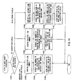
- Fig. 25 shows an example of the configuration of a conventional circuit design support system.
- This conventional circuit design support system 2500 comprises a control unit 2510, storage unit 2520, display unit 2530 and input unit 2540.
- the control unit 2510 further comprises logical synthesis processing 2511, delay analysis processing 2512 and correspondence display processing 2513
- the storage unit 2520 further comprises RTL description information 2521, route information 2522, logical circuit information 2523, delay report information 2524 and correspondence information 2525.
- the RTL description information 2521 which is the circuit information of the RTL description
- the route information 2522 which is information on the start point and the end point of the route of the path when the delay is analyzed, is input and stored in the storage unit 2520 by the designer.
- the logical synthesis processing 2511 generates logical circuit information 2523, which is the circuit information of the gate level description of the route, based on the RTL description information 2521 and the route information 2522, and stores it in the storage unit 2520.
- the logical synthesis processing 2511 also creates the correspondence information 2525, which indicates the correspondence relationship between the RTL description information 2521 and the logical circuit information 2523, and stores it in the storage unit 2520.
- the delay analysis processing 2512 analyzes the delay of the logical circuit and creates the delay report information 2524 based on the logical circuit information 2523, and stores it in the storage unit 2520.
- the correspondence display processing 2513 displays the RTL description corresponding to the gate which has the delay on the display unit 2530 based on the RTL description information 2521, the delay report information 2524 and the correspondence information 2525. By this, the area to be corrected of the RTL description can be clarified.
- the RTL description is generated by the behavioral synthesis of the behavior level description using a conventional circuit design support system 2500, and logical synthesis is performed, there is no means of corresponding the behavior level description before behavioral synthesis and the RTL description after behavioral synthesis, so the designer opens each description by an editor and performs confirmation and correction while estimating the correspondence relationship.
- the designer checks the design while estimating the correspondence relationship between the behavior level description before behavioral synthesis and the RTL description after behavioral synthesis, so the design operation consumes time, and correspondence mistakes occur.
- a computer program product in a computer readable medium, including computer program instructions thereon which when executed by a computer display information on a circuit information described according to each design level in circuit design, the computer program instructions implementing a method comprising: acquiring behavior level description information in which circuit information is described by description of a behavior level; acquiring lower level description information in which circuit information on a same circuit as the behavior level description information is described in a design level lower than the behavior level; acquiring correspondence information for making correspondence between a part of the behavior level description information and a part of the lower level description information; and displaying the correspondence between the part of the behavior level description information and the part of the lower level description information based on the correspondence information.
- a circuit design support method for displaying information on a circuit information described according to each design level in circuit design comprising: acquiring behavior level description information in which circuit information is described by description of a behavior level; acquiring lower level description information in which circuit information on a same circuit as the behavior level description information is described in a design level lower than the behavior level; acquiring correspondence information for making correspondence between a part of the behavior level description information and a part of the lower level description information; and displaying the correspondence between the part of the behavior level description information and the part of the lower level description information based on the correspondence information.
- a circuit design support system for displaying information on a circuit information described according to each design level in circuit design, comprising: a behavior level description information acquisition unit for acquiring behavior level description information in which circuit information is described by description of a behavior level; a lower level description information acquisition unit for acquiring lower level description information in which circuit information on a same circuit as the behavior level description information is described in a design level lower than the behavior level; a correspondence information acquisition unit for acquiring correspondence information for making correspondence between a part of the behavior level description information and a part of the lower level description information; and a display unit for displaying the correspondence between the part of the behavior level description information and the part of the lower level description information based on the correspondence information.
- the behavior level description and the lower level description are corresponded and displayed, so the user can easily comprehend this correspondence relationship. Therefore the design operation time (checks and corrections) of the user, for the behavior level description corresponding to the portion of the lower level description, can be decreased, and the design efficiency can be improved. Also the behavior level description and the lower level description are corresponded and displayed, so the user can accurately comprehend this correspondence relationship. As a result, the user need not make correspondence errors, and design defects can be decreased.
- the configuration of the circuit design support system according to First Embodiment of the present invention will be described with reference to the block diagram in Fig. 1.
- composing elements with a same reference number refer to the same elements throughout, of which description is omitted unless it is necessary.
- the circuit design support system according to the present embodiment is a system for executing processing to display with corresponding the behavior level description and the RTL description.
- This circuit design support system 100 is comprised of computers, such as a personal computer and a server computer.
- the circuit design support system 100 may be comprised not of a single computer but of a plurality of computers.
- the circuit design support system 100 comprises a control unit 110, storage unit 120, display unit 130 and input unit 140.
- the display unit 130 is a display device, such as a monitor.
- the input unit 140 is an input device, such as a keyboard and mouse.
- the control unit 110 is a control processing device, such as a CPU.
- the control unit 110 executes various processings based on a pre-stored OS program and application programs prestored in the storage unit 120.
- the programs for the behavioral synthesis processing 111 and the correspondence display processing 112 are stored in the storage unit 120, and the behavioral synthesis processing 111 and the correspondence display processing 112 are executed based on these programs.
- the storage unit 120 is comprised of internal storage means, such as a hard disk, and external storage means, such as an optical disk, where the OS program, application programs and various data required for processing each program are stored.
- behavior level description information 121, RTL description information 122 and behavior level - RTL correspondence information 123 are stored as the various data.
- application programs such as programs for the behavioral synthesis processing 111 and the correspondence display processing 112 are stored in the storage unit 120, although these programs are not shown in Fig. 1.
- the behavior level description information 121 is the circuit information of the behavior level description.
- the behavior level description information 121 is input to the input unit 140 by a user, such as a designer, and is stored in the storage unit 120, for example.
- the behavior level description information 121 is comprised of an arbitrary number of files, and the file format is text, for example.
- the behavior level description is a description that is a higher level than RTL description, and describes the system behavior. This behavior level description is in C language, for example.
- the RTL description information 122 is the circuit information of the RTL description.
- the RTL description information 122 is generated by the behavioral synthesis processing 111, and is stored in the storage unit 120.
- the RTL description information 122 is comprised of an arbitrary number of files, and the file format is text, for example.
- the RTL description describes the connection of combined circuits and registers.
- the RTL description is described in HDL (Hardware Description Language), such as Verilog - HDL or VHDL, for example.
- RTL description information 122 is not limited to an RTL description, and may be information on circuits on the design level, which is lower than the behavior level, such as the function level, gate level, transistor level and layout design level.
- the behavior level - RTL correspondence information 123 is the correspondence information between the line number of the behavior level description and the line number of the RTL description.
- the behavior level - RTL correspondence information 123 is generated by the behavioral synthesis processing 111, and is stored in the storage unit 120.
- the data structure of the behavior level - RTL correspondence information 123 will be described later.
- the behavioral synthesis processing 111 is the processing to be executed in the control unit 110.
- the behavior level description information 121 is input, and by performing the synthesizing operation on this information, the RTL description information 122 is generated and stored in the storage unit 120.
- the behavioral synthesis processing 111 creates the behavior level - RTL correspondence information 123 during behavioral synthesis, and stores it in the storage unit 120.
- the behavioral synthesis processing 111 is the processing of the synthesis unit for generating the RTL description information 122 and the behavior level - RTL correspondence information 123 based on the behavior level description information 121.
- the behavioral synthesis processing 111 may be executed by a system that is different from the circuit design support system 100.
- the correspondence display processing 112 is the processing to be executed by the control unit 110.
- the behavior level description information 121, RTL description information 122 and behavior level - RTL correspondence information 123 are output, and the behavior level description and RTL description are corresponded and displayed on the display unit 130.
- the correspondence display processing 112 is processing by the behavior level description information acquisition unit for acquiring the behavior level description information 121, the lower level description information acquisition unit for acquiring the RTL description information 122 (lower level description information), the correspondence information acquisition unit for acquiring the behavior level - RTL correspondence information 123, and the display unit for corresponding and displaying the behavior level description information 121 and the RTL description information 122 based on the behavior level - RTL correspondence information 123.
- the detailed operation of the correspondence display processing 112 will be described later.
- Fig. 2A shows the data structure of the behavior level - RTL correspondence information 123
- Fig. 2B is an example of data stored as the behavior level - RTL correspondence information 123.
- the line number of the behavior level description (main.c in the case of this example) and the line number of the RTL description (main.v in the case of this example) are corresponded with each other by bi-directional pointers.
- One line and one line can be corresponded, or one line and a plurality of lines can be corresponded.
- the 44 th line of main.c is corresponded to the 104 th line and the 114 th line of main.v.
- the file name and the line number of the corresponding source (behavior level description) and the file name and the line number of the corresponding destination (RTL description) are corresponded respectively, as shown in Fig. 2B.
- the line number of the reference destination can be easily acquired, whether the reference is from the behavior level description side or from the RTL description side.
- the present invention is not limited to this example, but other data structures may be used if correspondence of one line and a plurality of lines is possible.
- the unit of correspondence is not limited to lines, but may be lines and the number of columns, character strings or the position information of a location in the behavior level description information 121 and the RTL description information 122 stored in the storage unit 120 (e.g. address, if the storage unit 120 is a memory, or a physical location on the disk, if the storage unit 120 is a hard disk).
- This display screen is displayed on the display unit 130 by the correspondence display processing 112.
- This display screen is an example of a screen where the behavior level description information 121 and the RTL description information 122 are corresponded and displayed.
- This display screen 300 is displayed by one window, for example, as Fig. 3 shows.
- the display screen 300 is comprised of two display areas: a behavior level description display 301 for displaying the behavior level description information 121, and the RTL description display 302 for displaying the RTL description information 122.
- a behavior level description display 301 for displaying the behavior level description information 121
- the RTL description display 302 for displaying the RTL description information 122.
- the line numbers and the character strings of each description are displayed in the behavior level description display 301 and the RTL description display 302, but the line numbers need not be displayed.
- each description is displayed as a character string, but one or both of each description may be displayed as a graphic.
- the behavior level description information 121 may be displayed as a flow chart and the RTL description display 302 may be displayed as a circuit diagram.
- the following display operation if a part of the graphics or text is clicked on, then the corresponding part of the graphic and text is highlight-displayed.
- information the same as the element corresponded by the later mentioned behavior level - RTL correspondence information 123 such as a line number and a character string, are embedded in the graphic.
- an identifier which is assigned to each one of the coordinate positions or the graphic and graphic composing elements, is corresponded, instead of a line number, by the later mentioned behavior level - RTL correspondence information 123.
- a tab 303 to indicate a file name to be displayed, is disposed, and one or a plurality of files can be selected and displayed. Because of this, even if one file and a plurality of files are corresponded or if a plurality of files and a plurality of files are corresponded, the files can be displayed in one window.
- a plurality of files exist only in the area of the behavior level description display 301, but a plurality of files may also exist in the area of the RTL description display 302 in some cases.
- the plurality of files may be displayed not by tabs but by overlaying a plurality of windows, or a plurality of files may be simultaneously displayed by dividing the area of the behavior level description display 301 or the area of the RTL description display 302.
- the Find command for searching character strings and the Reload command for reading a file again are disposed as an example of the menu 304.
- commands for other processing may be disposed.
- an edit command may be disposed so that each file can be edited.
- the behavior level description display 301 and the RTL description display 302 display files corresponded before and after behavioral synthesis.
- the user can select lines which are corresponded to each other out of the behavior level description display 301 and the RTL description display 302.
- a line which has a corresponding destination, is underlined and highlight-displayed in the behavior level description display 301 and the RTL description display 302.
- This highlight display is not limited to an underline, but may be an arbitrary display method.
- a line which has a corresponding destination may be selected without highlighting, but only by selection. Only the corresponding lines out of the file content may be displayed in the behavior level description display 301 and the RTL description display 302, or only the corresponding line numbers may be displayed.
- the selected line is highlight-displayed in bold red, and the line corresponding to this line is highlighted in the same way.
- the corresponding line of the RTL description display 302 is highlight-displayed, and if the user selects a line of the RTL description display 302, the corresponding line of the behavior level description display 301 is highlight-displayed.
- the clicked line becomes bold red.
- the line corresponding to the 104 th line of the RTL description display 302 is the 44 th line of the behavior level description information 121, so the 44 th line of the behavior level description display 301 becomes bold red.
- the highlight display method is not limited to this example, but may be an arbitrary display method. It is also possible to design such that the user can select only underlined lines which have corresponding lines, and cannot select other lines.
- a plurality of lines which are corresponded in the display may be selectable.
- lines in another area corresponding to the plurality of selected lines may be highlight-displayed by the same display method, or the respective correspondence relationship may be distinguished by color coding each selected line.
- the selection target and the location of the correspondence display need not be line units, but may be a character string unit (e.g. "i” or "tmp").
- the selection method may be a keyboard instead of a pointing device, such as a mouse. In this case, possible methods are specification by cursor position, inputting a line number or inputting a character string.
- the position where each element is disposed in the display screen 300 is not limited to this example, but may be an arbitrary position.
- the behavior level description display 301 and the RTL description display 302 may be in separate windows, or a separate window may be created for each file of the behavior level description and the RTL description. Both need not be displayed all the time, and it may be designed such that clicking in a status where one is displayed displays the corresponding other.
- This processing is executed by the control unit 110 using the program of the correspondence display processing 112.
- This processing may be started by the user starting up the program of the correspondence display processing 112, or may be started when the behavioral synthesis processing 111 ends.
- the control unit 110 can acquire the behavior level description information 121 and the RTL description information 122 to be displayed by reading the file names stored in the behavior level - RTL correspondence information 123.
- File names of the behavior level description information 121 and the RTL description information 122 respectively may be input by the user.
- the file names of the behavior level - RTL correspondence information 123 are predetermined, then input by the user is unnecessary.
- a structure to easily estimate the file names of the behavior level description information 121 and the RTL description information 122 from the files names of the behavior level - RTL correspondence information 123 e.g. reattaching a suffix, such as a file extension
- the behavior level description display processing is executed (S402).
- the behavior level description information 121 is displayed on the behavior level description display 301 shown in Fig. 3.
- the RTL description display processing is executed (S403).
- the RTL description information 122 is displayed on the RTL description display 302 shown in Fig. 3.
- the user input processing is executed (S404).
- the correspondence display is executed. Details on processing from S402 to S404 will be described later.
- the processing sequence from S402 to S404 is not limited to this, but may be executed in other sequences.
- S402 and S403 may be reversed in execution, or S404 may be executed after S402 or S403 is executed, and S402 or S403 may be executed when the user selects the behavior level description display 301 and the RTL description display 302.
- the behavior level description information 121 acquires in S401 is displayed on the behavior level description display 301 on the display unit 130. For example, if a plurality of files of the behavior level description information 121 exist in the behavior level - RTL correspondence information 123, all the files may be displayed. Also, regardless the file format stored in the behavior level description information 121, the character strings of text may be displayed.
- the line numbers having a corresponding destination in the behavior level description are searched (S502).
- the line numbers of the behavior level description information 121 having a corresponding line number of the RTL description information 122 are searched.
- line numbers 40, 42, 43, 44, 46, 49, 50, 51, 52, 53 and 57 are detected from the line number list in main.c.
- S501 - S503 need not be in this sequence.
- the sequence of S501 and S502, for example, may be reversed.
- a plurality of processings may be executed simultaneously (in parallel).
- S501 and S503 may be executed in parallel after S502. In this case, it is unnecessary to execute the processing of changing the character string displayed in 501 to the underlined display in S503, and the lines to be underline-displayed in S503 can be underline-displayed from the beginning.
- the RTL description information 122 acquired in S401 is displayed in the RTL description display 302 on the display unit 130. Then the line numbers having a corresponding destination in the RTL description are searched (S602). From the line number list of the RTL description information 122, included in the behavior level - RTL correspondence information 123, the line numbers of the RTL description information 122 having corresponding line numbers in the behavior level description information 121 are searched. Then a line with an applicable line number is underlined (S603). Based on the line number of the RTL description information searched in S602, all applicable lines are underlined in the RTL description display 302. By this, the RTL description display 302 is displayed, and in this status, the user can select this display.
- S701 First it is judged which display the user selected (S701). Input by the user through the input unit 140 is accepted, and it is judged which display the user selected on the display screen 300 in Fig. 3. Depending on the selected location, S702 or S705 is executed. Here processing in the case of selecting a display other than the behavior level description display 301 and the RTL description display 302 is omitted.
- the selected line number is acquired (S702). If the user selected the behavior level description display 301, the line number of the selected line is acquired in the behavior level description display 301. At this time, the character string of the line of the acquired line number may be highlight-displayed in bold red, for example.
- the line number of the RTL description corresponding to the selected line number is searched (S703). From the line number list of the behavior level description information 121 included in the behavior level - RTL correspondence information 123, the line number acquired in S702 is searched, and all the line numbers of the RTL description information 122 corresponding to this line are determined.
- the selected line number is acquired (S705). If the user selected the RTL description display 302, the line number of the selected line is acquired in the RTL description display 302. Just like S702, the selected line may be highlight-displayed.
- the line number of the behavior level description corresponding to the selected line number is searched (S706). From the line number list of the RTL description information 122 included in the behavior level - RTL correspondence information 123, the line number acquired in S705 is searched, and all the line numbers of the behavior level description information 121 corresponding to this line are determined.
- the RTL description corresponding to the behavior level description can be displayed according to the selection by the user, and the behavior level description corresponding to the RTL description can be displayed. Therefore the user can easily specify the location in the RTL description corresponding to the location in the behavior level description, and can accurately check the kind of RTL description the behavior level description will become. Therefore design efficiency can be improved, and design defects can be decreased.
- this circuit design support system executes processing to correspond and display the behavior level description, the RTL description and the delay report.
- this circuit design support system further comprises a logical synthesis processing 113 in the control unit 110, and comprises the intra-RTL correspondence information 124, gate-RTL correspondence information 125 and delay report information 126 in the storage unit 110.
- the delay report information 126 is the delay information of a path of which the start point is the input terminal or storage element, and the end point is the output terminal or storage element.
- the delay report information 126 is generated by the logical synthesis processing 113, and is stored in the storage unit 120.
- the delay report information 126 is comprised of an arbitrary number of paths, and the format thereof is an internal format (e.g. binary format) of logical synthesis. Therefore data on the delay time can be directly referred to from the control unit 110, without executing such processing as a character string analysis of the text.
- the delay report is information acquired as a result of analyzing the delay of the behavior of each gate at logical synthesis.
- the delay report is comprised of the delay information on one or more paths.
- the delay information of a path includes, for example, the hierarchy and instance name of each gate from the start point to the end point of the path, the delay time of each gate, the delay time of an entire patch, and whether the delay rule was violated or not. Details on the delay report will be described later.
- the intra-RTL correspondence information 124 is the correspondence information between the instance name of a component (e.g. computing element, selector, register, terminal, wire) in the RTL description and the line number in the RTL description.
- the intra-RTL correspondence information 124 is generated by the behavioral synthesis processing 111, and is stored in the storage unit 120. The data structure will be described later.
- the gate-RTL correspondence information 125 is the correspondence information between the instance name of the gate in the delay report and the instance name of the component in the RTL description.
- the gate-RTL correspondence information 125 is generated by the logical synthesis processing 113, and is stored in the storage unit 120. The data structure will be described later.
- the logical synthesis processing 113 is executed by the control unit 110.
- the RTL description information 122 is input and logical synthesis is performed on this to generate the delay report information 126, and this delay report information 126 is stored in the storage unit 120.
- the logical synthesis processing 113 creates the gate-behavior level correspondence information 125 at logical synthesis, and stores it in the storage unit 120.
- the logical synthesis processing 113 may be executed in a system that is separate from the circuit design support system 100. In logical synthesis, a gate net list, which is the connection information between gates, is output, in addition to the delay report information 126 and the gate-behavior level correspondence information 125.
- intra-RTL correspondence information 124 is created in addition to the RTL description information 122 and the behavior level - RTL correspondence information 123 when behavioral synthesis is performed for the behavior level description information 121, and this information is stored in the storage unit 120.
- the delay report information 126, intra-RTL correspondence information 124 and gate-RTL correspondence information 125 are input in addition to the behavior level description information 121, RTL description information 122 and behavior level - RTL correspondence information 123, and the behavior level description, RTL description and delay report are corresponded and displayed on the display unit 130. Detailed operation will be described later.
- Fig. 9A shows an example of the data of the intra-RTL correspondence information 124.
- Fig. 9B shows an example of the data of the gate-RTL correspondence information 125.
- Fig. 9A shows, in the intra-RTL correspondence information 124, the file name of the RTL description, the instance name of a component of the RTL description and the line number of the RTL description where this instance name is written are included, and each element is corresponded to one another.
- the instance name of the component "INST_5" in the file "main.v" of the RTL description corresponds to the 104 th line of the RTL description.
- the intra-RTL correspondence information 124 the hierarchical information, the function type on whether it is an adder, subtractor or register, the input and output terminal names of the instance and the bit width information may also be included.
- AS Fig. 9B shows, in the gate-RTL correspondence information 125, the path name, instance name of a gate in the delay report, file name of the RTL description, instance name of a component in the RTL description and bit position of a component in the RTL description are included, and the respective elements are corresponded with one another.
- the bit position of a component in the RTL description the bit of FF (flip-flop) of the component in the RTL description is stored in the case when the component of the RTL description is a multi-bit register.
- the instance name "RG_28_reg1" of the gate in the path name "path 1" and “path 2" corresponds to the instance name "RG_28” of the component in the file "main.v” of the RTL description and the bit position "1" of the component.
- bit position remains blank.
- instances with the instance name "INST_4" and “INST_5" of the components of the RTL description are not separated into each bit on the gate level, so the bit position of a component of the RTL description is slashed, and remains blank.
- the instance name of the gate of the delay report and the instance name of the component of the RTL description correspond to each other one-to-one, but may correspond one-to-plural, plural-to-one or plural-to-plural.
- a plurality of instances are listed in the columns of the instance names of the gate of the delay report and the instance names of the components of the RTL description. Or an instance may be limited to one for each column, and a line may be divided.
- the gate-RTL correspondence information 125 may not have information on the bit position of a component of the RTL description. In this case, if the component of the RTL description is a multi-bit register, the instance name of the gate of the delay report and the instance name of the component of the RTL description correspond to each other as plural-to-one.
- Fig. 10A is an example of the display screen for displaying the delay report.
- Fig. 10B is a diagram depicting the path of the delay report in Fig. 10A.
- the display screen 1000 shown in Fig. 10A comprises a delay repot display 100 for displaying the delay report information 126.
- 1000 in Fig. 10A only one path, path 1, is displayed, but actually a plurality of paths are listed in the same display format before and after the displayed position.
- the correspondence display processing 112 has the display screen 300 shown in Fig. 3, and the display screen 1000, so as to display the behavior level description information 121, the RTL description information 122 and the delay report information 126.
- the display screen 300 and the display screen 1000 may be in one window or may be displayed in separate windows.
- a tab 303 may be created for each path, or a menu 304 for search may be created.
- the path “path1” is a path between the first bit of the register “RG_28” and the thirty first bit of the register “RG_28” in the hierarchy “INST_2", as shown in Fig. 10B, and this path passes through the hierarchy "INST_5" and the hierarchy "INST_4".
- "RG_28” is a flip-flop (FF).
- the line starting with “INST_2” indicates the gate or terminal of the hierarchy where this path passes through.
- "/" included in each line indicates the separation of hierarchies.
- "INST_2" indicates the hierarchy
- "RG_28_reg1” indicates the instance name
- "No1” indicates the terminal name of an instance
- "TBDFHAX1” indicates the element name.
- "RG_28_reg1” indicates the FF (flip-flop) at the first bit of the multi-bit register called "RG_28” in the RTL description.
- the multi-bit register having the instance name "RG_28” is separated into a 1-bit FF in the gate.
- the instance name of RTL t "_reg" + the bit position is assigned as the instance name of the gate.
- the column of Incr which is the second column from the right end in the delay report display 1001, indicates the delay time of each element.
- the column of Path which is the first column at the right end in the delay report display 1001, indicates the cumulative value of the delay time of each element.
- “r” at the right of the delay time indicates the delay time at the rise of the signal, and “f” indicates the delay time at the fall of the signal.
- “data arrival time” on the ninth line from the bottom of the screen is the delay time of the entire path.
- data required time on the third line from the bottom of the screen is the'reference delay value determined from the operating frequency.
- "slack" on the first line at the bottom of the screen indicates whether this delay time of the path violates the delay rule.
- correspondence display processing 112 will be described with reference to the flow chart shown in Fig. 12. Just like the processing shown in Fig. 4, this processing is executed by the control unit 110 using the program of the correspondence display processing 112.
- S1201 to S1203 are the same as S401 to S403 in Fig. 4 respectively, and S1206 is the same as S405 in Fig. 4, for which description will be omitted unless necessary.
- the user inputs the correspondence information (S1201).
- the user inputs a file name, etc. of the behavior level - RTL correspondence information 123, intra-RTL correspondence information 124 and gate - RTL correspondence information 125, which are inputs of the correspondence display processing 112.
- the behavior level - RTL correspondence information 123 and intra-RTL correspondence information 124, the behavior level description information 121 and RTL description information 122 to be displayed can be acquired, and by the gate - RTL correspondence information 125, the delay report information 126 can be acquired.
- the user may input the file name, etc. of the behavior level description information 121, RTL description information 122 and delay report information 126.
- the behavior level description display processing is executed (S1202), and the behavior level description display 301 is displayed. And then the RTL description display processing (S1203) is executed, and the RTL description display 302 is displayed.
- the delay report display processing is executed (S1204).
- the delay report information 126 is displayed on the delay report display 1001 shown in Fig. 10.
- the user input processing is executed (S1205).
- the correspondence display according to the user selection is executed. Details on the processing in S1204 and S1205 will be described later.
- the delay report is displayed in text (S1301). This processing is the same as S501 in Fig. 5.
- the delay report information 126 acquired in S1201 is displayed in the delay report display 1001 on the display unit 130.
- the delay report information 126 of the present embodiment has an internal format, such as binary format, stored in the storage unit 120, so each data is converted into text format to which the necessary character strings are added, and is displayed as Fig. 10.
- the instance names of the RTL description corresponding to the acquired instance names are searched (S1409). For each of the instance names acquired in S1408, an instance name of a gate of the delay report included in the gate - RTL correspondence information 125 is searched, and the instance name of the component of the RTL description corresponding to the instance name of the gate of the delay report is determined.
- the line numbers of the RTL description corresponding to the acquired instance names are searched (S1410). For each of the instance names searched and determined in S1409, the instance name of the component of the RTL description included in the intra-RTL correspondence information 124 is searched, and the line number of the RTL description corresponding to the instance name of the component of the RTL description is determined.
- the RTL description and the delay report corresponding to the behavior level description can be displayed according to the selection by the user, and the behavior level description and the delay report corresponding to the RTL description can be displayed, and the behavior level and the RTL description corresponding to the delay report can be displayed. Therefore the user can easily and accurately specify the location in the behavior level description and the location in the RTL description, which indicates the delay rule violation in the delay report. As a result, the location of the delay rule violation can be efficiently corrected, the design efficiency can be improved, and design defects can be decreased.
- the circuit design support system according to the present embodiment executes processing to correspond and display the behavior level description and the delay report.
- This circuit design support system 100 comprises the behavior level - RTL correspondence information 127 and the gate - behavior level correspondence information 128 instead of the behavior level - RTL correspondence information 123, intra-RTL correspondence information 124 and gate - RTL correspondence information 125 in Fig. 8.
- the behavior level - RTL correspondence information 127 is the correspondence information between the instance names of the components in the RTL description and the line numbers of the behavior level description.
- the behavior level - RTL correspondence information 127 is generated by the behavioral synthesis processing 111, and stored in the storage unit 120. The data structure will be described later.
- the gate - behavior level correspondence information 128 is the correspondence information between the instance names of the gate of the delay report and the line numbers of the behavior level description.
- the gate - behavior level correspondence information 128 is generated by the logic synthesis processing 113, and is stored in the storage unit 120. The data structure will be described later.
- the RTL description information 122 and the behavior level - RTL correspondence information 127 are created and stored in the storage unit 120 when the behavioral synthesis is performed on the behavior level description information 121.
- the behavior level - RTL correspondence information 127 is input in addition to the RTL description information 122, and the delay report information 126 and the gate - behavior level correspondence information 128 are created by logical synthesis, and are stored in the storage unit 120.
- the behavior level description information 121, the delay report information 126 and the gate - behavior level correspondence information 128 are input, and the behavior level description and the delay report are corresponded and displayed on the display unit 130. Details operation will be described later.
- Fig. 16A shows an example of the data of the behavior level - RTL correspondence information 127
- Fig. 16B shows an example of the data of the gate - behavior level correspondence information 128.
- Fig. 16A shows, in the behavior level - RTL correspondence information 127, a file name of the RTL description, an instance name of a component of the RTL description, a file name of the behavior level description and a line number of the behavior level description are included, and each element is corresponded to one another.
- the instance name "INST_5" of the component in the file "main.v” of the RTL description corresponds to the 44 th line of the file "main.c" of the behavior level description.
- a path name of the delay report As Fig. 16B shows, in the gate - behavior level correspondence information 128, a path name of the delay report, an instance name of a gate in the delay report, a file name of the behavior level description and a line number of the behavior level description are included and corresponded to one another.
- the instance name "RG_28_reg1" of the gate in the paths, "path1" and "path 2”, in the delay report corresponds to the 10 th and 85 th lines of the file "main.c" of the behavior level description.
- the behavior level description information 121 and the delay report information 126 are corresponded and displayed, so the display screen of this processing comprises the behavior level description display 301 and the delay report display 1001 in Fig. 3 and Fig. 10.
- the processing of the correspondence display processing 112 becomes the processing on the behavior level description processing 121 and the delay report information 126 in the flow chart shown in Fig. 12, that is S1201, S1202, S1204, S1205 and S1206.
- S1701 First it is judged which display the user selected (S1701), and S1702 or S1705 is executed depending on the location selected by the user. If the behavior level description display 301 is selected in S1701, the selected line number is acquired (S1702).
- the line numbers of the delay report corresponding to the selected line number are searched (S1703). From the line numbers of the behavior level description information 121 included in the gate - behavior level correspondence information 128, the line numbers acquired in S1702 are searched, and the path name and the instance name of the gate of the delay report corresponding to these lines are all determined.
- the line number of the behavior level description corresponding to the acquired instance names is searched (S1706). For each instance name acquired in S1705, an instance name of the gate of the delay report included in the selected path is searched in the gate - behavior level correspondence information 128, and all the line .numbers of the behavior level description information 121 corresponding to the instance name of the path are acquired.
- the delay report corresponding to the behavior level description can be displayed according to the selection by the user, and the behavior level description corresponding to the delay report can be displayed without going through an RTL description. Therefore the user can easily and accurately specify the location in the behavior level description, which indicates the delay rule violation in the delay report. Also the correspondence information required for the correspondence display processing is only the gate - behavior level correspondence information 128, so the data capacity required for the system can be decreased.
- the circuit design support system executes the processing to correspond and display the behavior level description, RTL description and delay report generated by another system.
- This circuit design support system 100 comprises the delay report analysis processing 114 instead of the logical synthesis processing 113 in Fig. 8, in the control unit 110, and comprises the delay report analysis information 129 instead of the gate - RTL correspondence information 125 in Fig. 8, in the storage unit 120.
- the delay report analysis information 129 is the information on the rules for analyzing the text of the delay report information 126.
- the delay report analysis information 129 is input by the user and is stored in the storage unit 120. The data structure will be described later.
- the delay report information 126 has the same information content as the delay report information in Fig. 8, but is acquired from a system (or a program) that is different from this system (or this program), and is input to the storage unit 120 by such means as a file copy. Therefore the stored format is different from the delay report information in Fig. 8.
- the delay report information 126 is a text format file, for example.
- the delay report information 126 is analyzed on the delay generated by such tools as STA (Statistic Timing Analysis), which is not shown in the drawing or by another system.
- the delay report analysis processing 114, delay report information 126, delay report analysis information 129 and intra - RTL correspondence information 124 are input, the text of the delay report information 126 is analyzed based on the delay report analysis information 129, and the analysis result is output to the correspondence display processing 112.
- the analysis result of the delay report analysis processing 114 is input in addition to the behavior level description information 121, the RTL description information 122, and the behavior level - RTL correspondence information 123, and the behavior level description, and RTL description and delay report are corresponded and displayed on the display unit 130. Detailed operation will be described later.
- the delay report analysis information 129 is comprised of the bus expansion rule, hierarchy separation rule, instance name renaming rule and target hierarchy rule.
- %s%d in the bus expansion rule indicates that the instance name is separated into a character string and a decimal numeric, and the numeric value is regarded as a bit number of the bus.
- "/" and "$" of the hierarchy separation rule indicate that the hierarchy is the character string separated by "/" or "$".
- “_reg” of the instance name renaming rule indicates that a character string, when this character string is deleted, has the possibility to be an instance name of the RTL description.
- a plurality of character strings may be listed.
- a normal expression rather than a character string may be used.
- level 12 of the target hierarchy rule indicates that the hierarchy at the second level from the top and below can be the analysis target of the hierarchy.
- the behavior level description information 121, RTL description information 122 and delay report information 126 are corresponded and displayed, so the display screen of this processing is the same as Fig. 3 and Fig. 10.
- the delay report display 1001 shown in Fig. 11 may be displayed, instead of the one in Fig. 10.
- Fig. 11A is an example of a display screen for displaying the delay report.
- Fig. 11B is a diagram depicting a path of the delay report in Fig. 11A.
- the hierarchy TOP is dispersed at the higher level of the hierarchy "INST_2" in a path of the delay report, and "$" in addition to "/" are used as the separators of the hierarchy in the delay report.
- the processing of the correspondence display processing 112 is the same as the flow chart shown in Fig. 12.
- the flow chart of the delay report display processing S1204 is the same as Fig. 13, but the delay report information 126 is in text format, so in the processing in S1301, the delay report in text format is displayed as is.
- the user input processing (S1205) in this processing will be described with reference to the flow chart shown in Fig. 20. Just like the processing shown in Fig. 14, this processing is executed by the control unit 110 using the program of the correspondence display processing 112.
- S2001 to S2007 are the same as S1401 to S1407 in Fig. 14 for which description is omitted.
- S2008 is the same as S1408 in Fig. 14 and S2011 is the same as S1411 in Fig. 14, for which description is omitted unless it is necessary.
- the instance name of the gate acquired in S1408 is converted into the instance name of the RTL description using the gate - RTL correspondence information 125 in S1409, but in Fig. 20, these two processings are executed together in S2009.
- the delay report display is selected in S2001, the selected path in the delay report is analyzed using the delay report analysis information 129, and the instance name of the RTL is estimated (S2009). From the path selected by this processing, all the candidates of the instance names of RTL can be listed. Details of this processing will be described later.
- the delay report analysis processing (S2009) in Fig. 20 will be described using the flow chart shown in Fig. 21.
- This processing is the processing of the delay report analysis processing 114 in Fig. 22, and just like the processing in Fig. 20, this processing is executed by the control unit 110 using the program of the correspondence display processing 112.
- the delay report information 126 is a delay report shown in Fig. 11, and the delay report analysis information 129 is information shown in Fig. 19.
- the selected path is analyzed by the hierarchy separation rule (S2101).
- the hierarchy separation rule of the delay report analysis information 129 each line of the delay report information 126 is separated, and the separated character strings are regarded as hierarchies.
- the hierarchy separation rule is "/, $", so "INST_2" and "INST_4" in Fig. 11 are analyzed as hierarchies.
- the second hierarchy from the bottom is recognized as an instance of the gate, and the hierarchy at the very bottom is recognized as a terminal of the instance.
- the hierarchy at the very bottom is recognized as a terminal of the instance.
- the selected path is analyzed (S2102).
- the hierarchy of the target hierarchy rule and below is the analysis target.
- the target hierarchy rule is "level 2", so when the character string at the highest hierarchy is deleted, only the two hierarchies or more which remain under that become the target.
- the subsequent analysis target is one that is two hierarchies or more in the hierarchy "INST_2" or below.
- the partial path which became the analysis target in S2102 is analyzed, and the original (in the RTL description) instance name is estimated (S2103).
- a character string recognized as an instance name in S2101 is acquired, and this character string is separated into the instance name and the bit position.
- the bus expansion rule is "%s%d", so the character string and the decimal number are separated, and the last character of the character string is regarded as the bit number of the bus, and the rest of the character string is the instance name.
- the instance name is "RG_28_reg”
- the bit position is 1 in the analysis result.
- RG_28_reg31 can be estimated either that the instance name is “RG_28_reg3" and the bit position is "1", or the instance name is "RG_28_reg” and the bit position is "31". It is also possible that the instance does not have a bit width, and in this case the instance name is "RG_28_reg31". These candidates are all listed, and estimation continues using the instance name renaming rule next.
- the candidates of the instance names are analyzed according to the instance name renaming rule, and the original (in the RTL description) instance name is estimated (S2104).
- Candidates where the character string of the instance name renaming rule is deleted from the character string are newly created.
- the instance name renaming rule is "_reg”, so a character string when this character string is deleted from the instance name is added to the candidates. For example, from the instance name "RG_28_reg", the instance name "RG_28” is created and added to the candidates.
- the candidates acquired from path1 in Fig. 11 are "RG_28_reg1", “RG_28_reg”, “RG_28”, “INST_5", “INST_”, “add_2353”, “add_235”, “add_23”, “add_2”, “add_”, “U1_1”, “U1_”, “U1_31”, “U1_3”, “INST_4", “add_2344”, “add_234", "U1_2”, “U18008”, “U1800”, “U180", “U18”, “U1”, “U16304", “U1630", “U163", “U16", “U17504", “U1750”, “U175", “U17”, “RG_28_reg31” and “RG_28_reg3".
- the RTL description and the delay report corresponding to the behavior level description can be displayed according to the selection by the user, and the behavior level description and the delay report corresponding to the RTL description can be displayed, and the behavior level description and the RTL description corresponding to the delay report can be displayed.
- a delay rule violation is detected first in the delay analysis after layout design (e.g. violation did not occur in logical analysis but delays became longer when wiring is considered)
- there is no means of displaying the RTL description corresponding to the path which violated the delay rule and the behavior level description corresponding to the path which violated the delay rule cannot be displayed.
- a delay report in text format is analyzed, so the behavior level description and the RTL description can be corresponded and displayed not only for the delay report by logical synthesis but also for the delay report by STA after layout.
- the processing of the delay report analysis processing S2009 shown in the above example is the case when the delay report analysis information has a bus expansion rule, hierarchy separation rule, instance name renaming rule and target hierarchy rule, but one or more of these rules may not be available. In this case, processing using these rules is omitted, and the candidates are listed based on other rules. Rules other than the bus expansion rule, hierarchy separation rule, instance name renaming rule and target hierarchy rule may be available. In this case, processing corresponding to these rules is newly added, and the candidates are listed based on these rules.
- the circuit design support system according to the present embodiment executes processing to correspond and display the behavior level description, RTL description and delay report using the rule desired by the user.
- This circuit design support system 100 comprises the gate - RTL correspondence information 125 in the storage unit 120, in addition to the configuration in Fig. 18.
- the content of the information is the same as Fig. 8, however it is not generated by logical synthesis processing, but is input by the user.
- the gate - RTL correspondence information 125 may be created by disposing the logical synthesis processing in the control unit 110.
- the RTL description and the delay report corresponding to the behavior level description can be displayed according to the selection by the user, and the behavior level description and the delay report corresponding to the RTL description can be displayed, and the behavior level description and the RTL description corresponding to the delay report can be easily displayed. Therefore from the delay report acquired by various logical synthesis tools and layout design tools, a desired path can be selected and displayed in correspondence with the behavior level and the RTL description.
- the delay report is input for the correspondence display processing, but the gate net Fist, which is the output of logical synthesis, may be input for the correspondence display processing 112.
- the behavior level description, RTL description and gate net list can be corresponded and displayed.
- the behavior level is described in C language, but the present invention is not dependent on the language of the behavior level description.
- C language C++, System C, Spec C, ANSI-C, and a derivative language thereof, or system Verilog, for example, may be used.
- Verilog a language as Verilog or VHDL, used for RTL description, is used for the behavior level description.
- the static display screen shown in Fig. 23 may be displayed.
- the delay time is indicated by the bar graph 2301 for each path of the delay report. This can clarify a path which violates the delay rule.
- the portion indicating the route of the path is the button 2302, and the display screen 300 of the above mentioned correspondence display may be displayed by clicking this button 2302.
- Fig. 24 shows an example of the hardware configuration for implementing the above circuit design support system 100.
- a standard computer system can be used, comprising a central processing unit (CPU) 201 and a memory 204.
- CPU central processing unit
- memory 204 for the circuit design support system 100, a standard computer system can be used, comprising a central processing unit (CPU) 201 and a memory 204.
- the CPU 201 and the memory 204 are connected to the hard disk device 213, which is an auxiliary storage device, via the bus.
- the flexible disk device 220, hard disk devices 213 and 230, and a storage medium drive such as a CD-ROM drives 226 and 229, and an MO drive 228 are connected to the bus via various controllers, such as the flexible disk controller 219, IDE controller 225 and SCSI controller 227.
- a portable storage medium such as a flexible disk, is inserted.
- Computer programs for sending instructions to the CPU 201, and executing the functions of the circuit design support system 100, along with the operating system, can be stored.
- Computer programs are executed by being loaded into the memory 204.
- Computer programs can be compressed or divided into a plurality of parts when stored in the storage medium.
- the standard hardware configuration comprises user interface hardware.
- the user interface hardware includes a pointing device (e.g. mouse 207, joy stick) and a keyboard 206 for input, or a display device 211, such as a liquid crystal display, and a CRT display 212 for displaying visual data to the user.
- a pointing device e.g. mouse 207, joy stick
- a keyboard 206 for input
- a display device 211 such as a liquid crystal display
- CRT display 212 for displaying visual data to the user.
- a printer can be connected via the parallel port 216.
- This computer system can connect a modem via the serial port 215, and is connected to a network via the serial port 215, modem or token ring or communication adaptor 218, to communicate with other computer systems.
- the above configuration can be omitted according to necessity.
- operation to check/correct the path, of which a delay rule violation is detected, description can be performed quickly and easily in the original behavior level for circuits designed using behavioral synthesis, by using the report after logical synthesis and the STA report after layout. Also when a circuit is designed using behavioral synthesis, it is possible to check what type of RTL description will be the description at a specific location of the behavior level description. It is also possible to check what kind of behavior level description becomes what kind of RTL description.
Abstract
Description
Recently to improve design efficiency, a method that converts the behavior level description of C language into an RTL description by behavioral synthesis is attracting attention. Behavioral synthesis is disclosed, for example, in Giovanni DeMicheli: "Synthesis and Optimization of Digital Circuits," McGraw - Hill, Inc., 1994, pp. 141 - 266.
Therefore in Japanese Unexamined Patent Application Publication No. 5-242183, a method for corresponding the delay report and the RTL description is disclosed.
Claims (19)
- A computer program product, in a computer readable medium, including computer program instructions thereon which when executed by a computer display information on a circuit information described according to each design level in circuit design, the computer program instructions implementing a method comprising:acquiring behavior level description information in which circuit information is described by description of a behavior level;acquiring lower level description information in which circuit information on a same circuit as the behavior level description information is described in a design level lower than the behavior level;acquiring correspondence information for making correspondence between a part of the behavior level description information and a part of the lower level description information; anddisplaying the correspondence between the part of the behavior level description information and the part of the lower level description information based on the correspondence information.
- The computer program product according to Claim 1, wherein the displaying of the correspondence comprises:selecting by a user a part of the lower level description information;searching the correspondence information based on the selected part and determining a part of the behavior level description information corresponding to the selected part; andhighlighting the determined part.
- The computer program product according to Claim 1, wherein the displaying of the correspondence comprises:selecting by a user a part of the behavior level description information;searching the correspondence information based on the selected part and determining a part of the lower level description information corresponding to the selected part; andhighlighting the determined part.
- The computer program product according to Claim 1, wherein the displaying of the correspondence comprises:searching the correspondence information and determining a plurality of parts of the behavior level description information in which the corresponding parts of the lower level description information exist;'highlighting the plurarity of parts and prompting a user to select a part out of the plurarity of parts;searching the correspondence information based on the selected part and determining a part of the lower level description information corresponding to the selected part; andhighlighting the determined part of the lower level description information.
- The computer program product according to Claim 1, wherein the displaying of the correspondence comprises:searching the correspondence information and determining a plurality of parts of the lower level description information in which the corresponding parts of the behavior level description information exist;highlighting the plurarity of parts and prompting a user to select a part out of the plurarity of parts; searching the correspondence information based on the selected part and determining a part of the behavior level description information corresponding to the selected part; andhighlighting the determined part of the behavior level description information.
- The computer program product according to Claim 1, wherein the lower level description information is information on a circuit described in Register Transfer Level (RTL).
- The computer program product according to Claim 1, wherein the lower level description information is delay information of a gate in a gate level.
- The computer program product according to Claim 1, wherein the lower level description information is a gate net list in a gate level.
- The computer program product according to Claim 1, wherein the lower level description information is delay information of a gate in layout design.
- The computer program product according to Claim 1, wherein the lower level description information includes RTL circuit information described by Register Transfer Level (RTL) and delay information of a gate in a gate level.
- The computer program product according to Claim 1, wherein the correspondence information is information for making correspondence between a line of the behavior level description information and a line of the lower level description information.
- The computer program product according to Claim 7, wherein the correspondence information is information for making correspondence between a line of the behavior level description information and a gate of the delay information.
- The computer program product according to Claim 9, wherein the correspondence information is information for making correspondence between a line of the behavior level description information and a gate of the delay information.
- The computer program product according to Claim 10, wherein the correspondence information includes information for making correspondence between a line of the behavior level description information and a line of the RTL circuit information, and information for making correspondence between a line of the RTL circuit information and a gate of the delay information.
- The computer program product according to Claim 1, wherein the lower level description information and the correspondence information are generated based on the behavior level description information.
- A circuit design support method for displaying information on a circuit information described according to each design level in circuit design, comprising:acquiring behavior level description information in which circuit information is described by description of a behavior level;acquiring lower level description information in which circuit information on a same circuit as the behavior level description information is described in a design level lower than the behavior level;acquiring correspondence information for making correspondence between a part of the behavior level description information and a part of the lower level description information; anddisplaying the correspondence between the part of the behavior level description information and the part of the lower level description information based on the correspondence information.
- The circuit design support method according to Claim 16, wherein the lower level description information and the correspondence information are generated based on the behavior level description information.
- A circuit design support system for displaying information on a circuit information described according to each design level in circuit design, comprising:a behavior level description information acquisition unit for acquiring behavior level description information in which circuit information is described by description of a behavior level;a lower level description information acquisition unit for acquiring lower level description information in which circuit information on a same circuit as the behavior level description information is described in a design level lower than the behavior level;a correspondence information acquisition unit for acquiring correspondence information for making correspondence between a part of the behavior level description information and a part of the lower level description information; anda display unit for displaying the correspondence between the part of the behavior level description information and the part of the lower level description information based on the correspondence information.
- The circuit design support system according to Claim 18, further comprising a synthesis unit for generating the lower level description information and the correspondence information based on the behavior level description information.
Applications Claiming Priority (2)
| Application Number | Priority Date | Filing Date | Title |
|---|---|---|---|
| JP2004053481 | 2004-02-27 | ||
| JP2004053481A JP2005242812A (en) | 2004-02-27 | 2004-02-27 | Circuit design support system, circuit design support method, and program |
Publications (2)
| Publication Number | Publication Date |
|---|---|
| EP1569144A2 true EP1569144A2 (en) | 2005-08-31 |
| EP1569144A3 EP1569144A3 (en) | 2006-05-03 |
Family
ID=34747540
Family Applications (1)
| Application Number | Title | Priority Date | Filing Date |
|---|---|---|---|
| EP05003887A Withdrawn EP1569144A3 (en) | 2004-02-27 | 2005-02-23 | System, method and program to display correspondence between behavioral and low level descriptions of an integrated circuit |
Country Status (3)
| Country | Link |
|---|---|
| US (1) | US7370297B2 (en) |
| EP (1) | EP1569144A3 (en) |
| JP (1) | JP2005242812A (en) |
Families Citing this family (8)
| Publication number | Priority date | Publication date | Assignee | Title |
|---|---|---|---|---|
| JP2007034584A (en) * | 2005-07-26 | 2007-02-08 | Toshiba Corp | High order composition device, automatic high order composition method, high order composition program, and gate net list automatic verifying method |
| JP2007102271A (en) * | 2005-09-30 | 2007-04-19 | Nec Corp | Circuit design support system and method |
| JP4779908B2 (en) * | 2006-09-22 | 2011-09-28 | 日本電気株式会社 | Circuit design support system, circuit design support method, and program |
| JP4881769B2 (en) * | 2007-03-16 | 2012-02-22 | 株式会社リコー | Semiconductor integrated circuit design support apparatus, semiconductor integrated circuit design support method, semiconductor integrated circuit design support program |
| JP2009211606A (en) * | 2008-03-06 | 2009-09-17 | Nec Corp | Circuit design support system, display method of circuit design support system, and program |
| JP2010033540A (en) * | 2008-06-25 | 2010-02-12 | Toshiba Corp | Apparatus and method for estimating change amount in register transfer level structure |
| US9189134B2 (en) * | 2011-09-30 | 2015-11-17 | Bmc Software, Inc. | Display window with multi-layer, parallel tab display |
| US10078723B1 (en) * | 2016-09-30 | 2018-09-18 | Cadence Design Systems, Inc. | Method and apparatus for design rules driven interactive violation display |
Citations (3)
| Publication number | Priority date | Publication date | Assignee | Title |
|---|---|---|---|---|
| US5727187A (en) * | 1995-08-31 | 1998-03-10 | Unisys Corporation | Method of using logical names in post-synthesis electronic design automation systems |
| EP0847022A2 (en) * | 1996-12-03 | 1998-06-10 | Motorola, Inc. | Method for designing an architectural system |
| US5937190A (en) * | 1994-04-12 | 1999-08-10 | Synopsys, Inc. | Architecture and methods for a hardware description language source level analysis and debugging system |
Family Cites Families (6)
| Publication number | Priority date | Publication date | Assignee | Title |
|---|---|---|---|---|
| JP2853431B2 (en) | 1992-02-03 | 1999-02-03 | 日本電気株式会社 | Delay analysis result display method |
| US5867395A (en) * | 1996-06-19 | 1999-02-02 | Lsi Logic Corporation | Gate netlist to register transfer level conversion tool |
| US5940779A (en) * | 1997-03-05 | 1999-08-17 | Motorola Inc. | Architectural power estimation method and apparatus |
| US6874135B2 (en) * | 1999-09-24 | 2005-03-29 | Nec Corporation | Method for design validation using retiming |
| US6704908B1 (en) * | 1999-11-17 | 2004-03-09 | Amadala Limited | Method and apparatus for automatically generating a phase lock loop (PLL) |
| US7137078B2 (en) * | 2003-03-27 | 2006-11-14 | Jasper Design Automation, Inc. | Trace based method for design navigation |
-
2004
- 2004-02-27 JP JP2004053481A patent/JP2005242812A/en active Pending
-
2005
- 2005-02-23 EP EP05003887A patent/EP1569144A3/en not_active Withdrawn
- 2005-02-25 US US11/065,535 patent/US7370297B2/en not_active Expired - Fee Related
Patent Citations (3)
| Publication number | Priority date | Publication date | Assignee | Title |
|---|---|---|---|---|
| US5937190A (en) * | 1994-04-12 | 1999-08-10 | Synopsys, Inc. | Architecture and methods for a hardware description language source level analysis and debugging system |
| US5727187A (en) * | 1995-08-31 | 1998-03-10 | Unisys Corporation | Method of using logical names in post-synthesis electronic design automation systems |
| EP0847022A2 (en) * | 1996-12-03 | 1998-06-10 | Motorola, Inc. | Method for designing an architectural system |
Non-Patent Citations (1)
| Title |
|---|
| BLACKBURN R L ET AL: "CORAL II: linking behavior and structure in an IC design system" PROCEEDINGS OF THE DESIGN AUTOMATION CONFERENCE. ANAHEIM, JUNE 12 - 15, 1988, PROCEEDINGS OF THE DESIGN AUTOMATION CONFERENCE (DAC), NEW YORK, IEEE, US, vol. CONF. 25, 12 June 1988 (1988-06-12), pages 529-535, XP010013022 ISBN: 0-8186-0864-1 * |
Also Published As
| Publication number | Publication date |
|---|---|
| US20050193360A1 (en) | 2005-09-01 |
| EP1569144A3 (en) | 2006-05-03 |
| JP2005242812A (en) | 2005-09-08 |
| US7370297B2 (en) | 2008-05-06 |
Similar Documents
| Publication | Publication Date | Title |
|---|---|---|
| US6684376B1 (en) | Method and apparatus for selecting components within a circuit design database | |
| US6516456B1 (en) | Method and apparatus for selectively viewing nets within a database editor tool | |
| EP1569144A2 (en) | System, method and program to display correspondence between behavioral and low level descriptions of an integrated circuit | |
| US6366874B1 (en) | System and method for browsing graphically an electronic design based on a hardware description language specification | |
| US6910200B1 (en) | Method and apparatus for associating selected circuit instances and for performing a group operation thereon | |
| US6889370B1 (en) | Method and apparatus for selecting and aligning cells using a placement tool | |
| US7921390B2 (en) | Method and system for creating, viewing, editing, and sharing output from a design checking system | |
| US6009251A (en) | Method and system for layout verification of an integrated circuit design with reusable subdesigns | |
| US6701289B1 (en) | Method and apparatus for using a placement tool to manipulate cell substitution lists | |
| US7062427B2 (en) | Batch editor for netlists described in a hardware description language | |
| US6212666B1 (en) | Graphic representation of circuit analysis for circuit design and timing performance evaluation | |
| JPH11191116A (en) | System design and evaluation cad system and program storage medium therefor | |
| US20100017777A1 (en) | Method and apparatus for synthesizing a hardware system from a software | |
| US20070168741A1 (en) | Method, system and program product for facilitating debugging of simulation results obtained for an optimized simulation model of a device design having hierarchically-connected components | |
| JP2007122589A (en) | Mixed signal circuit simulator | |
| US7493578B1 (en) | Correlation of data from design analysis tools with design blocks in a high-level modeling system | |
| US9557989B2 (en) | Comparison and merging of IC design data | |
| US7076410B1 (en) | Method and apparatus for efficiently viewing a number of selected components using a database editor tool | |
| US7420573B1 (en) | System and method for merging electronic diagrams | |
| US7000206B2 (en) | Timing path detailer | |
| US20050223345A1 (en) | Circuit design assistant system, circuit design method, and program product for circuit design | |
| US20110099530A1 (en) | Spine selection mode for layout editing | |
| US6983430B2 (en) | Method of resolving mismatched parameters in computer-aided integrated circuit design | |
| US6968518B2 (en) | Method of resolving missing graphical symbols in computer-aided integrated circuit design | |
| Rubin | Using the electric vlsi design system |
Legal Events
| Date | Code | Title | Description |
|---|---|---|---|
| PUAI | Public reference made under article 153(3) epc to a published international application that has entered the european phase |
Free format text: ORIGINAL CODE: 0009012 |
|
| AK | Designated contracting states |
Kind code of ref document: A2 Designated state(s): AT BE BG CH CY CZ DE DK EE ES FI FR GB GR HU IE IS IT LI LT LU MC NL PL PT RO SE SI SK TR |
|
| AX | Request for extension of the european patent |
Extension state: AL BA HR LV MK YU |
|
| PUAL | Search report despatched |
Free format text: ORIGINAL CODE: 0009013 |
|
| AK | Designated contracting states |
Kind code of ref document: A3 Designated state(s): AT BE BG CH CY CZ DE DK EE ES FI FR GB GR HU IE IS IT LI LT LU MC NL PL PT RO SE SI SK TR |
|
| AX | Request for extension of the european patent |
Extension state: AL BA HR LV MK YU |
|
| 17P | Request for examination filed |
Effective date: 20060323 |
|
| AKX | Designation fees paid |
Designated state(s): DE GB |
|
| 17Q | First examination report despatched |
Effective date: 20070725 |
|
| STAA | Information on the status of an ep patent application or granted ep patent |
Free format text: STATUS: THE APPLICATION HAS BEEN WITHDRAWN |
|
| 18W | Application withdrawn |
Effective date: 20071031 |