EP1569388A1 - Distributed dynamic routing - Google Patents
Distributed dynamic routing Download PDFInfo
- Publication number
- EP1569388A1 EP1569388A1 EP05396007A EP05396007A EP1569388A1 EP 1569388 A1 EP1569388 A1 EP 1569388A1 EP 05396007 A EP05396007 A EP 05396007A EP 05396007 A EP05396007 A EP 05396007A EP 1569388 A1 EP1569388 A1 EP 1569388A1
- Authority
- EP
- European Patent Office
- Prior art keywords
- edge device
- network
- packet
- routing
- address
- Prior art date
- Legal status (The legal status is an assumption and is not a legal conclusion. Google has not performed a legal analysis and makes no representation as to the accuracy of the status listed.)
- Granted
Links
Images


Classifications
-
- H—ELECTRICITY
- H04—ELECTRIC COMMUNICATION TECHNIQUE
- H04L—TRANSMISSION OF DIGITAL INFORMATION, e.g. TELEGRAPHIC COMMUNICATION
- H04L45/00—Routing or path finding of packets in data switching networks
-
- H—ELECTRICITY
- H04—ELECTRIC COMMUNICATION TECHNIQUE
- H04L—TRANSMISSION OF DIGITAL INFORMATION, e.g. TELEGRAPHIC COMMUNICATION
- H04L12/00—Data switching networks
- H04L12/28—Data switching networks characterised by path configuration, e.g. LAN [Local Area Networks] or WAN [Wide Area Networks]
- H04L12/46—Interconnection of networks
- H04L12/4604—LAN interconnection over a backbone network, e.g. Internet, Frame Relay
- H04L12/4608—LAN interconnection over ATM networks
-
- H—ELECTRICITY
- H04—ELECTRIC COMMUNICATION TECHNIQUE
- H04L—TRANSMISSION OF DIGITAL INFORMATION, e.g. TELEGRAPHIC COMMUNICATION
- H04L12/00—Data switching networks
- H04L12/28—Data switching networks characterised by path configuration, e.g. LAN [Local Area Networks] or WAN [Wide Area Networks]
- H04L12/46—Interconnection of networks
- H04L12/4604—LAN interconnection over a backbone network, e.g. Internet, Frame Relay
- H04L12/462—LAN interconnection over a bridge based backbone
-
- H—ELECTRICITY
- H04—ELECTRIC COMMUNICATION TECHNIQUE
- H04L—TRANSMISSION OF DIGITAL INFORMATION, e.g. TELEGRAPHIC COMMUNICATION
- H04L12/00—Data switching networks
- H04L12/28—Data switching networks characterised by path configuration, e.g. LAN [Local Area Networks] or WAN [Wide Area Networks]
- H04L12/46—Interconnection of networks
- H04L12/4633—Interconnection of networks using encapsulation techniques, e.g. tunneling
-
- H—ELECTRICITY
- H04—ELECTRIC COMMUNICATION TECHNIQUE
- H04L—TRANSMISSION OF DIGITAL INFORMATION, e.g. TELEGRAPHIC COMMUNICATION
- H04L12/00—Data switching networks
- H04L12/66—Arrangements for connecting between networks having differing types of switching systems, e.g. gateways
-
- H—ELECTRICITY
- H04—ELECTRIC COMMUNICATION TECHNIQUE
- H04L—TRANSMISSION OF DIGITAL INFORMATION, e.g. TELEGRAPHIC COMMUNICATION
- H04L45/00—Routing or path finding of packets in data switching networks
- H04L45/50—Routing or path finding of packets in data switching networks using label swapping, e.g. multi-protocol label switch [MPLS]
-
- H—ELECTRICITY
- H04—ELECTRIC COMMUNICATION TECHNIQUE
- H04L—TRANSMISSION OF DIGITAL INFORMATION, e.g. TELEGRAPHIC COMMUNICATION
- H04L2212/00—Encapsulation of packets
Definitions
- the invention relates to telecommunications.
- the invention relates to a novel and advanced method and system for routing packets in a distributed and dynamic manner.
- IP Internet protocol
- a telecommunication network comprises a set of nodes and a medium connecting them.
- the data to be transmitted from the source node to the destination node usually is divided into a set of data packets, which are each transmitted via their own routes to the destination node.
- the source node and the destination node are disposed in different networks, so the data packets may travel via several different networks.
- an individual network typically comprises numerous nodes implementing the routing function i.e. routers.
- routers When traveling from the source node to the destination node, a data packet propagates from one router to another. Each router maintains a routing table comprising a set of destination address prefixes and next-hop addresses corresponding to them.
- the term "next hop" is used to mean a router to which it is advantageous to direct the data packet next on its way towards its destination.
- this router reads the destination address of the destination node of the data packet.
- the router retrieves from its routing table the next-hop address, corresponding to the network part of the destination address, i.e. to the destination address prefix of the data packet, and sends the data packet to this determined next hop.
- the router functioning as the next hop does the same thing.
- the data packet propagates from one router to another until it arrives at such a router that is disposed in the same network as the destination node, whereby the router in question typically sends the data packet directly to the destination address.
- the determined next hop may be disposed in a different network than the router of that moment. Often, however, the determined next hop is disposed in the same network as the router of that moment, whereby the data packet travels via several different routers on its way through an individual network. Each router makes its own routing decision.
- CIDR Classless Interdomain Routing
- a set of destination address prefixes of a routing table is grouped to form one group based on network topologies. This enables one to reduce the number of entries in the routing table.
- this may result in that some destination addresses correspond to several different destination address prefixes of the routing table.
- one must choose from the different destination address prefixes of the routing table the most suitable one, i.e. the longest one. If the alternatives are e.g. 208.12.16/20 and 208.12.21/24, then 208.12.21/24 is chosen because it is longer, i.e. 24 bits long. This operation is called the longest match operation or the longest matching prefix operation.
- the problem with the conventional routing is, however, inefficiency, resulting from the fact that the routing decision is made for each packet in each router.
- the routing decisions are made at the L3 layer level (Level 3, L3), i.e. at the network layer level, resulting in that the detection of faults, locating them and recovering from them must also be performed at the L3 layer level. This is very slow when compared e.g. to such a situation in which these procedures could be made at the L2 layer level (Level 2, L2), i.e. at the data link layer level.
- Level 3, L3 the L3 layer level
- L2 layer level Level 2, L2
- MPLS routing Multiprotocol Label Switching, MPLS.
- MPLS Multiprotocol Label Switching
- TE Traffic Engineering
- the objective of the present invention is to disclose a novel method and system that eliminate the aforementioned disadvantages or at least significantly alleviate them.
- One specific objective of the invention is to disclose a method and system that enable one to route packets in a distributed and dynamic manner in packet-switched telecommunication networks.
- packets are routed in a distributed and dynamic manner via one or more internal telecommunication networks.
- the internal telecommunication networks comprise each one or more edge devices.
- Each edge device connects the internal network to one or more external telecommunication networks.
- the internal and external networks are packet-switched.
- internal telecommunication network refers to a telecommunication network implementing the routing in accordance with the present invention.
- external telecommunication network refers to a telecommunication network that does not implement the routing of the invention.
- edge device refers to a node of the network that is disposed at the periphery of the network, i.e. is connected, in addition to its own network, also to a node of some other network.
- a data packet is received from an external telecommunication network to a source edge device.
- a next-hop address corresponding to the destination address prefix of the received data packet is determined in the source edge device.
- the term "source edge device” refers to a such an edge device that receives a data packet from an external telecommunication network.
- any edge device of an internal telecommunication network can function as the source edge device.
- target edge device next, there are determined the address and network interface of a target edge device, corresponding to the next hop which was determined in the source edge device. Thereafter, there is generated in the source edge device a transmission packet addressed to the determined target edge device, the transmission packet comprising the received data packet and the address of the determined next hop, as well as a network interface i.e. a port of the determined target edge device.
- target edge device refers to the edge device to which the generated transmission packet is addressed.
- any edge device of an internal telecommunication network can function as the target edge device.
- the generated transmission packet is transmitted from the source edge device to the determined target edge device via one or more internal telecommunication networks at the data link layer level.
- the data packet and the next-hop address, as well as the network interface of the target edge device are separated from the received transmission packet. Thereafter, the data packet is sent further via the network interface of the target edge device based on the next-hop address.
- next-hop address is an individual address or a network address. In case it is an individual address, the data packet is sent to the next-hop address. In case it is a network address, the data packet is sent to the destination address included therein.
- network routing information comprising destination address prefixes and corresponding next-hop addresses, as well as switching information of the network, comprising next-hop addresses, and addresses and network interfaces of the corresponding target edge devices.
- the routing and/or switching information maintained by the edge device in question is updated, and there is generated from the received network routing information and the associated network switching information an update packet, which is sent to one or more other edge devices.
- the network routing and/or switching information maintained by the edge device in question is updated, if necessary, based on the received update packet.
- the network routing information included in the received update packet is sent to one or more of the external networks to which the edge device in question is connected.
- a first internal telecommunication network is connected to a second internal telecommunication network by means of a gateway for transmitting transmission packets and update packets between the networks in question. There is maintained in the gateway the routing and switching information for both internal networks separately.
- the routing and/or switching information of the first internal telecommunication network that is maintained by the gateway is updated, if necessary; the received update packet is modified by replacing the network interfaces of the target edge devices thereof with the network interface of the gateway in question; the modified update packet is transmitted to one or more edge devices of a second external telecommunication network, and the routing and/or switching information of the network that is maintained by the edge devices which received the modified update packet is updated, if necessary.
- a transmission packet is transmitted from the source edge device of the second internal telecommunication network, which received the update packet, to the target edge device of the first internal telecommunication network, wherein the network interface of the target edge device of the transmission packet is replaced with the network interface of the gateway.
- the transmission packet is transmitted to the network interface of the gateway.
- the switching information maintained by the gateway is used to determine the network interface of the target edge device of the received transmission packet.
- the network interface of the gateway included in the transmission packet is replaced with the determined network interface of the target edge device.
- the transmission packet is sent further from the gateway to the target edge device in question.
- a data packet of the multicast type from an external telecommunication network to the source edge device in receiving a data packet of the multicast type from an external telecommunication network to the source edge device, it is transmitted to the multicast network interface of the target edge devices.
- service class-specific queues are arranged in one or more edge devices and/or gateways.
- one or more of the internal and/or external telecommunication networks are IP networks, that is a telecommunication network implementing the Internet protocol (IP).
- IP Internet protocol
- the present invention has the advantage that it enables the implementation of very efficient distributed routers.
- the efficiency is based on the fact that just one routing decision is made for a packet entering an internal telecommunication network.
- a decision is made at the same time as to what target edge device the packet is routed to.
- the packet is transmitted directly to the target edge device via an internal telecommunication network at the L2 layer level. Contrary to conventional routing, the packet thus does not travel on its way through the network via several different routers, in each of which, a new routing decision would be made at the L3 layer level.
- the routing in accordance with the present invention is very fault tolerant because as the packet is transmitted along the whole way from the source edge device to the target edge device at the L2 layer level, the detection of faults, locating them and recovering from them can be performed at the L2 layer level in the order of milliseconds, which is considerably faster than if these procedures had to be performed at the L3 layer level, like in conventional routing.
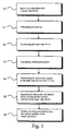
- Fig. 1 is a flow chart describing, by way of example, one method of the invention, by means of which method packets are routed in a distributed and dynamic manner via one or more internal packet-switched telecommunication networks.
- a data packet is received from an external packet-switched telecommunication network to a source edge device, step 10.
- a source edge device determines the next-hop address, corresponding to the destination address prefix of the received data packet, step 11.
- the method as shown in Fig. 1 determines the address and network interface of the target edge device corresponding to the next hop determined in the source edge device, step 12. Thereafter, at step 13, there is formed in the source edge device a transmission packet addressed to the determined target edge device comprising the received data packet, as well as the determined next-hop address and the network interface of the determined target edge device. Next, at step 14, the formed transmission packet is transmitted from the source edge device to the determined target edge device via one or more internal telecommunication networks at the data link layer level.
- the data packet and the next-hop address, as well as the network interface of the target edge device are separated from the received transmission packet, step 15.
- the next-hop address is an individual address or a network address.
- the data packet is sent further to the next-hop address via the network interface of the target edge device.
- it is a network address, it means that the final recipient of the data packet is disposed in the same sub-network as the network interface of the target edge device in question, so the data packet is sent further directly to the destination address included therein via the network interface of the target edge device.
- Fig. 2a is a flow chart illustrating the components of one exemplary system of the invention at general level.
- Fig. 2b is a flow chart illustrating, in more detail, the components of edge device RL1 as shown in Fig. 2a by way of example. The rest of the edge devices as shown in Fig. 2a are corresponding.
- Fig. 2c is a flow chart illustrating, in more detail, the components of the gateway GW as shown in Fig. 2a by way of example.
- the system as shown in Figs. 2a, 2b and 2c enables routing of packets in a distributed and dynamic manner.
- the system as shown in Figs. 2a, 2b and 2c by way of example comprises packet-switched internal telecommunication networks SV1, SV2, as well as packet-switched external telecommunication networks UV1, UV2, UV3, UV4 and UV5. Further, the system as shown in Figs. 2a, 2b and 2c by way of example comprises edge devices RL1, RL2, RL3 and RL5 for receiving data packets from external telecommunication networks. Edge devices RL1, RL2 and RL3 have been arranged in conjunction with internal telecommunication network SV1, and edge devices RL4 and RL5 have been arranged in conjunction with internal telecommunication network SV2.
- each edge device is connected, for the sake of clarity of the figure, just to one external telecommunication network, one or more edge devices can also be connected to several external telecommunication networks.
- internal telecommunication networks SV1, SV2 and external telecommunication networks UV1, UV2, UV3 UV4 and UV5 are IP networks.
- Each edge device can be connected to an external telecommunication network in some manner known per se, such as e.g. via a BGP interface (Border Gateway Protocol), via an OSPF interface (Open Shortest Path First) or via on ISIS interface (Intermediate System to Intermediate System).
- edge devices RL1, RL2, RL3, RL4 and RL5 each comprise a routing table RT1, RT2, RT3, RT4, RT5, respectively, for determining the next-hop address corresponding to the destination address prefix of the received data packet.
- routing tables RT1, RT2, RT3, RT4, RT5 have been arranged to maintain network's routing information comprising destination address prefixes and next-hop addresses corresponding to them.
- a routing table can be implemented using some applicable description known per se, or e.g. the longest match operation.
- edge devices RL1, RL2, RL3, RL4 and RL5 each comprise a switching table KT1, KT2, KT3, KT4, Kt5, respectively for determining the address of the target edge device corresponding to the determined next hop of the received data packet, as well as the network interface of this target edge device via which the next hop can be reached.
- switching tables KT1, KT2, KT3, KT4, KT5 have been arranged to maintain network's switching information comprising next-hop addresses and addresses and network interfaces of the target edge devices corresponding to them.
- the network interfaces of the switching tables can be e.g. edge device specific numbers that can be generated e.g. by indexing the ports of the edge device.
- a data packet is received to edge device RL1 of internal telecommunication network SV1 from external telecommunication network UV1.
- routing table RT1 of edge device RL1 is used to determine that the next hop corresponding to the destination address prefix of the data packet in question is e.g. a router R arranged in external telecommunication network UV3.
- switching table KT1 of edge device RL1 is used to determine that the target edge device corresponding to the next hop R in question is edge device RL3 of internal telecommunication network SV1, whose address and network interface are apparent from switching table KT1.
- edge devices RL1, RL2, RL3, RL4 and RL5 each comprise generation means 1 of a transmission packet for generating a transmission packet addressed to the determined target edge device.
- the transmission packet comprises the received data packet and the address of the determined next-hop and the network interface of the determined target edge device.
- edge devices RL1, RL2, RL3, RL4 and RL5 each comprise separation means 2 of the transmission packet for separating the data packet and the next-hop address and the network interface of the target edge device from the received transmission packet. It must be noted that e.g.
- next-hop address in the case of IP networks, it is possible to use in the transmission packet, as the next-hop address, the IP next-hop address in question or some suitable address index. If, for example, a 10 to 16-bit long index is used instead of 32-bit long IP addresses, a transmission packet to be transferred in an internal telecommunication network can be considerably minimized.
- edge devices RL1, RL2, RL3, RL4 and RL5 each comprise means for sending the data packet further 3 for sending the data packet further via the network interface of the target edge device based on the next-hop address.
- the means for sending the data packet further 3 comprise address means 31 for determining whether the next-hop address is an individual address or a network address for sending the data packet to the next-hop address, in case it is an individual address, and for sending the data packet to the destination address included therein, in case it is a network address.
- system as shown in Figs. 2a, 2b and 2c by way of example further comprises transmission means 4 of the transmission packet for transmitting the generated transmission packet from the source edge device to the determined target edge device via one or more internal telecommunication networks at the data link layer level.
- edge devices RL1, RL2, RL3, RL4 and RL5 each comprise update means 5 for updating the routing and switching tables of the edge device in question when receiving new or changed routing information of the network from an external network; for generating an update packet from the received routing information of the network and the associated switching information of the network; and for transmitting the generated update packet to one or more other edge devices.
- the routing and switching tables can be implemented e.g. so that the edge device comprises e.g. first and second routing and switching tables.
- the first routing and switching tables are updated based on the received routing information, but the second routing and switching tables are updated only if the received routing information comprises a new target network or a more advantageous route to a known network.
- the first routing and switching tables can thus determine several routes to the same target, but the second routing and switching tables determine just one, e.g. a more advantageous route.
- the update means 5 have been arranged to update, if necessary, the routing and switching tables of an edge device comprising the update means in question based on an update packet received from some other edge device, as well as to transmit the received network's routing information included in the update packet further to one or more of the external networks to which the edge device comprising the update means in question is connected.
- the routing information of the network can be transmitted from edge devices to external telecommunication networks using some applicable standard interface known per se.
- the system as shown in Figs. 2a, 2b and 2c by way of example comprises a gateway GW for connecting internal telecommunication network SV1 to internal telecommunication SV2 for transmitting transmission and update packets between the networks in question.
- the gateway GW comprises routing database DB1 for maintaining the routing and switching information of internal telecommunication network SV1, and routing database DB2 for maintaining the routing and switching information of internal telecommunication network SV2.
- the gateway GW further comprises update means 6 of the database for updating routing database DB1 or DB2, according to need, when receiving an update packet into the gateway from internal telecommunication network SV1 or SV2 in the aforementioned order.
- the gateway GW further comprises modification means 7 for modifying the received update packet by replacing the network interfaces of the target edge devices comprising the switching information with the network interface of the gateway GW.
- the gateway GW comprises transmission means 8 of the modified update packet for transmitting the modified update packet to one or more edge devices of internal telecommunication network SV1 or SV2.
- update means 5 arranged in the edge devices have been arranged to update, if necessary, the routing and switching tables of the edge device comprising the update means in question based on the modified update packet received by it.
- the gateway GW comprises replacement means 9 for determining, by means of routing databases, the network interface of the target edge device of the transmission packet received from an edge device of an internal telecommunication network, wherein the network interface of the target edge device of the received transmission packet has been replaced with the network interface of the gateway when sending the transmission packet in question from the source edge device; for replacing the gateway's network interface included in the transmission packet with the determined network interface of the target edge device; and for sending the transmission packet further from the gateway to the target edge device in question.
- edge devices RL1, RL2, RL3, RL4 and RL5 and the gateway GW comprise service class-specific queues. Between the queues it is possible to use some applicable method of allocating turns known per se for appropriately serving the service classes. In case the internal network provides means for transmitting packet-specific information, these means can be used. Otherwise, packet-specific service class information can be e.g. added to the transmission packet being generated.
- a multicast-type data packet is received to the source edge device from an external telecommunication network, it is transmitted to a predetermined multicast network interface of edge devices.
- the edge device recognizes that the data packet incoming from an external telecommunication network is of the multicast-type, it can send it to an internal telecommunication network e.g. either as being of the multicast or broadcast type, depending on the fact of which traffic type is supported by the internal telecommunication network in question.
- the packet is sent to a predetermined multicast port, which is not an actual network interface and which is congruent in all the edge devices. This can be implemented e.g.
- the switching table comprises a multicast/broadcast address and a multicast port.
- the edge device receives a packet addressed to a multicast port, the packet is transmitted to the interfaces of the external telecommunication network via which the multicast tree travels.
- the edge devices can be provided e.g. with a specific table describing the multicast addresses as numerals of the network interfaces of the edge devices.
- Each port performs routing of the actual multicast packet to the next hop.
- the control of the multicast traffic can be implemented e.g. by means of applicable standard interfaces known per se in connection to external telecommunication networks.
Abstract
Description
Claims (24)
- A method for routing packets in a distributed and dynamic manner via one or more internal telecommunication networks, the internal telecommunication networks each comprising one or more edge devices, which each edge device connects the internal network in question to one or more external telecommunication networks, which internal and external networks are packet-switched, the method comprising the steps of:characterized in that the method further comprises the steps of:receiving a data packet to a source edge device from an external telecommunication network; anddetermining in the source edge device the address of the next-hop corresponding to the destination address prefix of the received data packet,determining the address and network interface of a target edge device corresponding to the next hop determined in the source edge device;generating a transmission packet addressed to the target edge device determined in the source edge device, the transmission packet comprising the received data packet and the determined next-hop address and the determined network interface of the target edge device;transmitting the generated transmission packet from the source edge device to the determined target edge device via one or more internal telecommunication networks at the data link layer level;separating in the target edge device from the received transmission packet the data packet, as well as the next-hop address and the network interface of the target edge device; andsending the data packet further via said network interface of the target edge device based on said next-hop address.
- The method as defined in claim 1,
characterized in that sending the data packet further from the network interface of the target edge device comprises the steps of:determining whether said next-hop address is an individual address or a network address;in case it is an individual address, the data packet is sent to said next-hop address; andin case it is a network address, the data packet is sent to the destination address included therein. - The method as defined in claim 1 or 2, characterized in that network routing information is maintained in one or more edge devices, the routing information comprising destination address prefixes and corresponding next-hop addresses; as well as network switching information comprising addresses of the next-hop, and addresses and network interfaces of the corresponding target edge devices.
- The method as defined in claim 3,
characterized in that when receiving new or changed network routing information to the edge device from an external telecommunication network, the network routing and/or switching information maintained by the edge device in question is updated; and an update packet is formed from the received network routing information and the associated network switching information, which update packet is sent to one or more other edge devices. - The method as defined in claim 4,
characterized in that when receiving an update packet to the edge device, the network routing and/or switching information maintained by the edge device in question is updated, if necessary, based on the received update packet. - The method as defined in claim 5,
characterized in that the network routing information included in the received update packet is transmitted further to one or more of the external networks to which the edge device in question is connected. - The method as defined in any one of claims 1-6, characterized in that a first internal telecommunication network is connected to a second telecommunication network by means of a gateway for transmitting transmission packets and update packets between the networks in question, in which gateway there is maintained the routing and switching information for both internal telecommunication networks separately.
- The method as defined in claim 7,
characterized in that when receiving an update packet to the gateway from a first internal telecommunication network:updating, if necessary, the routing and/or switching information of the first internal telecommunication network maintained by the gateway;modifying the received update packet by replacing the network interfaces of the target edge devices that are included in the switching information with the network interface of the gateway in question;transmitting the modified update packet to one or more edge devices of the second internal telecommunication network; andupdating, if necessary, the routing and/or switching information maintained by the edge devices that received the modified update packet. - The method as defined in claim 8,
characterized in that
sending a transmission packet from a source edge device of the second internal telecommunication network that received the modified update packet to a target edge device of the first internal telecommunication network, wherein the network interface of the target edge device of the transmission packet is replaced with the network interface of the gateway;
transmitting the transmission packet to said network interface of the gateway;
determining, by means of the switching information maintained by the gateway, the network interface of the target edge device of the received transmission packet;
replacing the gateway's network interface included in the transmission packet with the determined network interface of the target edge device; and
sending the transmission packet further from the gateway to the target edge device in question. - The method as defined in any one of claims 1-9, characterized in that when receiving a data packet of the multicast type from an external telecommunication network to a source edge device, it is transmitted to the multicast network interface of target edge devices.
- The method as defined in any one of claims 1-10, characterized in that one or more edge devices and/or gateways are provided with service class-specific queues.
- The method as defined in any one of claims 1-11, characterized in that one or more of the internal and/or external telecommunication networks are IP networks.
- A system for routing packets in a distributed and dynamic manner, the system comprising:one or more internal telecommunication networks (SV1,...,SVN), which are packet-switched;one or more external telecommunication networks (UV1,...,UVN), which are packet-switched;one or more edge devices (RL1,...RLN) for receiving a data packet from an external telecommunication network, each edge device being arranged in conjunction with an internal telecommunication network for connecting the internal telecommunication network in question to one or more of the external telecommunication networks, one or more of the edge devices comprising:a routing table (RT1,..RTN) for determining the next-hop address corresponding to the destination address prefix of the received data packet,
characterized in that one more of the edge devices (RL1,...RLN) further comprise:a switching table (KT1,...KTN) for determining the address and network interface of the target edge device corresponding to the determined next hop of the received data packet;generation means (1) of a transmission packet for generating a transmission packet addressed to the determined target edge device, the transmission packet comprising the received data packet and the address of the determined next hop and the network interface of the determined target edge device;separation means (2) of the transmission packet for separating the data packet and the next-hop address and the network interface of the target edge device from the received transmission packet;means for sending the data packet further (3) for sending the data packet further via said network interface of the target edge device based on the next-hop address, and in that the system further comprises:transmission means (4) of the transmission packet for transmitting the generated transmission packet from the source edge device to the determined target edge device via one or more internal telecommunication networks at the data link layer level. - The system as defined in claim 13,
characterized in that the means for sending the data packet further (3) comprise:address means (31) for determining whether said next-hop address is an individual address or a network address; for sending the data packet to said next-hop address, in case it is an individual address; and for sending the data packet to the destination address included therein, in case it is a network address. - The system as defined in claim 13 or 14, characterized in that one or more of the routing tables (RT1,..RTN) have been arranged to maintain network's routing information comprising destination address prefixes and addresses of the next-hop corresponding to them.
- The system as defined in claim 15,
characterized in that one or more of the switching tables (KT1,...KTN) have been arranged to maintain network's switching information comprising addresses of the next-hop and addresses and network interfaces of the target edge devices corresponding to them. - The system as defined in claim 16,
characterized in that one or more of the edge devices (RL1,...RLN) further comprise update means (5) for updating the routing and switching tables of the edge device in question when receiving new or changed routing information of the network from an external network to the edge device; for generating an update packet from the received routing information of the network and the associated switching information of the network; and for transmitting the generated update packet to one or more other edge devices. - The system as defined in claim 17,
characterized in that one or more of the update means (5) have been further arranged to update, if necessary, the routing and switching tables of the edge device comprising the update means in question based on the update packet received by it. - The system as defined in claim 18,
characterized in that one or more of the update means (5) have been further arranged to transmit the network's routing information included in the update packet received by them further to one or more of the external networks to which the edge device comprising the update means in question is connected. - The system as defined in any one of claims 13-19, characterized in that the system further comprises:one or more gateways (GW) for connecting a first internal telecommunication network to a second internal telecommunication network for transmitting transmission packets and update packets between the networks in question, the gateway comprising:a first routing database (DB1) for maintaining the routing and switching information of the first internal telecommunication network, anda second routing database (DB2) for maintaining the routing and switching information of the second internal telecommunication network.
- The system as defined in claim 20,
characterized in that one or more of the gateways (GW) further comprise:update means (6) of the database for updating the first routing database, according to need, when receiving an update packet into the gateway from the first internal telecommunication network;modification means (7) for modifying the received update packet by replacing the network interfaces of the target edge devices that are included in the switching information with the network interface of the gateway in question;transmission means (8) of a modified update packet for transmitting the modified update packet to one or more edge devices of the second internal telecommunication network, and in thatone or more of the update means (5) have been further arranged to update, if necessary, the routing and switching tables of the edge device comprising the update means in question based on the modified update packet received by it. - The system as defined in claim 21,
characterized in that one or more of the gateways (GW) further comprise:replacement means (9) for determining, by means of routing databases, the network interface of the target edge device of the transmission packet received from an edge device of an internal telecommunication network, wherein said network interface of the target edge device of the received transmission packet has been replaced with the network interface of the gateway when sending the transmission packet in question from the source edge device; for replacing the gateway's network interface included in the transmission packet with the determined network interface of the target edge device; and for sending the transmission packet further from the gateway to the target edge device in question. - The system as defined in any one of claims 13-22, characterized in that one or more of the edge devices and/or gateways comprise service class-specific queues.
- The system as defined in any one of claims 13-23, characterized in that one or more of the internal and/or external networks are IP networks.
Applications Claiming Priority (2)
| Application Number | Priority Date | Filing Date | Title |
|---|---|---|---|
| FI20040285 | 2004-02-24 | ||
| FI20040285A FI117033B (en) | 2004-02-24 | 2004-02-24 | Distributed Dynamic Routing |
Publications (2)
| Publication Number | Publication Date |
|---|---|
| EP1569388A1 true EP1569388A1 (en) | 2005-08-31 |
| EP1569388B1 EP1569388B1 (en) | 2007-09-12 |
Family
ID=31725761
Family Applications (1)
| Application Number | Title | Priority Date | Filing Date |
|---|---|---|---|
| EP05396007A Active EP1569388B1 (en) | 2004-02-24 | 2005-02-15 | Distributed dynamic routing |
Country Status (6)
| Country | Link |
|---|---|
| US (1) | US7529239B2 (en) |
| EP (1) | EP1569388B1 (en) |
| JP (1) | JP4703213B2 (en) |
| AT (1) | ATE373361T1 (en) |
| DE (1) | DE602005002382T2 (en) |
| FI (1) | FI117033B (en) |
Cited By (2)
| Publication number | Priority date | Publication date | Assignee | Title |
|---|---|---|---|---|
| WO2010120827A1 (en) * | 2009-04-13 | 2010-10-21 | Qualcomm Incorporated | Split-cell relay packet routing |
| GB2583962A (en) * | 2019-05-16 | 2020-11-18 | Rockley Photonics Ltd | Routing protocol and distributed router |
Families Citing this family (22)
| Publication number | Priority date | Publication date | Assignee | Title |
|---|---|---|---|---|
| US6360100B1 (en) * | 1998-09-22 | 2002-03-19 | Qualcomm Incorporated | Method for robust handoff in wireless communication system |
| US7668541B2 (en) | 2003-01-31 | 2010-02-23 | Qualcomm Incorporated | Enhanced techniques for using core based nodes for state transfer |
| US6862446B2 (en) * | 2003-01-31 | 2005-03-01 | Flarion Technologies, Inc. | Methods and apparatus for the utilization of core based nodes for state transfer |
| US9078084B2 (en) | 2005-12-22 | 2015-07-07 | Qualcomm Incorporated | Method and apparatus for end node assisted neighbor discovery |
| US8983468B2 (en) | 2005-12-22 | 2015-03-17 | Qualcomm Incorporated | Communications methods and apparatus using physical attachment point identifiers |
| US8509799B2 (en) | 2005-09-19 | 2013-08-13 | Qualcomm Incorporated | Provision of QoS treatment based upon multiple requests |
| US9066344B2 (en) * | 2005-09-19 | 2015-06-23 | Qualcomm Incorporated | State synchronization of access routers |
| US9736752B2 (en) | 2005-12-22 | 2017-08-15 | Qualcomm Incorporated | Communications methods and apparatus using physical attachment point identifiers which support dual communications links |
| US8982835B2 (en) | 2005-09-19 | 2015-03-17 | Qualcomm Incorporated | Provision of a move indication to a resource requester |
| US8982778B2 (en) | 2005-09-19 | 2015-03-17 | Qualcomm Incorporated | Packet routing in a wireless communications environment |
| US9083355B2 (en) | 2006-02-24 | 2015-07-14 | Qualcomm Incorporated | Method and apparatus for end node assisted neighbor discovery |
| US8085794B1 (en) * | 2006-06-16 | 2011-12-27 | Emc Corporation | Techniques for fault tolerant routing in a destination-routed switch fabric |
| US9155008B2 (en) | 2007-03-26 | 2015-10-06 | Qualcomm Incorporated | Apparatus and method of performing a handoff in a communication network |
| US8830818B2 (en) | 2007-06-07 | 2014-09-09 | Qualcomm Incorporated | Forward handover under radio link failure |
| US9094173B2 (en) | 2007-06-25 | 2015-07-28 | Qualcomm Incorporated | Recovery from handoff error due to false detection of handoff completion signal at access terminal |
| US7940753B2 (en) * | 2007-11-29 | 2011-05-10 | Alcatel Lucent | Enhancing routing optimality in IP networks requiring path establishment |
| US8615241B2 (en) | 2010-04-09 | 2013-12-24 | Qualcomm Incorporated | Methods and apparatus for facilitating robust forward handover in long term evolution (LTE) communication systems |
| US8468268B2 (en) | 2010-08-26 | 2013-06-18 | Novell, Inc. | Techniques for identity and policy based routing |
| US8989046B1 (en) | 2012-11-12 | 2015-03-24 | The Aerospace Corporation | Inter-domain routing message distribution through wide area broadcast channel |
| US10826982B2 (en) | 2013-01-10 | 2020-11-03 | Nxp Usa, Inc. | Packet processing architecture and method therefor |
| CN106982163B (en) * | 2016-01-18 | 2020-12-04 | 华为技术有限公司 | Method and gateway for acquiring route on demand |
| CN111614560A (en) * | 2020-05-25 | 2020-09-01 | 山东汇贸电子口岸有限公司 | Distributed dynamic routing method |
Citations (2)
| Publication number | Priority date | Publication date | Assignee | Title |
|---|---|---|---|---|
| EP0845889A2 (en) * | 1996-11-29 | 1998-06-03 | Anritsu Corporation | Router for high-speed packet communication between terminal apparatuses in different LANs |
| US5825772A (en) * | 1995-11-15 | 1998-10-20 | Cabletron Systems, Inc. | Distributed connection-oriented services for switched communications networks |
Family Cites Families (18)
| Publication number | Priority date | Publication date | Assignee | Title |
|---|---|---|---|---|
| JPS6272252A (en) * | 1985-09-25 | 1987-04-02 | Nippon Telegr & Teleph Corp <Ntt> | Packet switching system |
| US6331983B1 (en) * | 1997-05-06 | 2001-12-18 | Enterasys Networks, Inc. | Multicast switching |
| JPH11112503A (en) * | 1997-09-30 | 1999-04-23 | Hitachi Ltd | Network system and network equipment |
| JP2001007848A (en) * | 1999-06-18 | 2001-01-12 | Toshiba Corp | Inter-network repeating method and inter-network repeater |
| JP4099930B2 (en) * | 2000-06-02 | 2008-06-11 | 株式会社日立製作所 | Router device and VPN identification information setting method |
| JP4225681B2 (en) * | 2000-12-06 | 2009-02-18 | 富士通株式会社 | Virtual closed network construction method and apparatus, and relay apparatus |
| WO2002056551A1 (en) | 2001-01-16 | 2002-07-18 | Xanten Ab | Routing of data packets below the ip-level in a packet-switched communication network |
| US7457239B2 (en) * | 2001-03-22 | 2008-11-25 | Hitachi, Ltd. | Method and apparatus for providing a quality of service path through networks |
| US7197549B1 (en) * | 2001-06-04 | 2007-03-27 | Cisco Technology, Inc. | On-demand address pools |
| FR2826211B1 (en) * | 2001-06-18 | 2004-12-10 | Cit Alcatel | METHOD AND DEVICE FOR LIGHTENING THE SIGNALING LOAD OF A "MULTI-TRANSMISSION" PROTOCOL USING A TRANSMISSION MEDIUM WHICH DOES NOT ALLOW MUTUAL LISTENING BETWEEN TERMINALS OF A NETWORK |
| DE60108387T2 (en) * | 2001-09-12 | 2005-12-29 | Alcatel | Method and apparatus for service differentiation in a data network |
| US7843923B2 (en) * | 2002-01-08 | 2010-11-30 | Verizon Services Corp. | Methods and apparatus for determining the port and/or physical location of an IP device and for using that information |
| US7277442B1 (en) * | 2002-04-26 | 2007-10-02 | At&T Corp. | Ethernet-to-ATM interworking that conserves VLAN assignments |
| JP2003338835A (en) * | 2002-05-20 | 2003-11-28 | Fujitsu Ltd | Packet switch and method |
| US7248579B1 (en) * | 2002-10-15 | 2007-07-24 | Cisco Technology, Inc. | System and method for providing a link state database (LSDB) snapshot for neighbor synchronization |
| JP4242407B2 (en) * | 2003-02-03 | 2009-03-25 | 日本電信電話株式会社 | Cut-through method and edge router |
| EP2034676B1 (en) * | 2003-02-03 | 2014-11-12 | Nippon Telegraph and Telephone Corporation | Edge router, Method and Program therefor |
| JP2005012381A (en) * | 2003-06-18 | 2005-01-13 | Nec Corp | Device and method for transferring data, data communication system using the same and program |
-
2004
- 2004-02-24 FI FI20040285A patent/FI117033B/en active IP Right Grant
-
2005
- 2005-02-15 DE DE602005002382T patent/DE602005002382T2/en active Active
- 2005-02-15 EP EP05396007A patent/EP1569388B1/en active Active
- 2005-02-15 AT AT05396007T patent/ATE373361T1/en not_active IP Right Cessation
- 2005-02-17 US US11/061,492 patent/US7529239B2/en active Active
- 2005-02-24 JP JP2005048308A patent/JP4703213B2/en active Active
Patent Citations (2)
| Publication number | Priority date | Publication date | Assignee | Title |
|---|---|---|---|---|
| US5825772A (en) * | 1995-11-15 | 1998-10-20 | Cabletron Systems, Inc. | Distributed connection-oriented services for switched communications networks |
| EP0845889A2 (en) * | 1996-11-29 | 1998-06-03 | Anritsu Corporation | Router for high-speed packet communication between terminal apparatuses in different LANs |
Non-Patent Citations (1)
| Title |
|---|
| "SWITCHED VIRTUAL NETWORKS INTERNETWORKING MOVES BEYOND BRIDGES AND ROUTERS", DATA COMMUNICATIONS, MCGRAW HILL. NEW YORK, US, vol. 23, no. 12, 1 September 1994 (1994-09-01), pages 66 - 70,72,74,, XP000462385, ISSN: 0363-6399 * |
Cited By (7)
| Publication number | Priority date | Publication date | Assignee | Title |
|---|---|---|---|---|
| WO2010120827A1 (en) * | 2009-04-13 | 2010-10-21 | Qualcomm Incorporated | Split-cell relay packet routing |
| US8532056B2 (en) | 2009-04-13 | 2013-09-10 | Qualcomm Incorporated | Device mobility for split-cell relay networks |
| US8867428B2 (en) | 2009-04-13 | 2014-10-21 | Qualcomm Incorporated | Split-cell relay application protocol |
| US9198112B2 (en) | 2009-04-13 | 2015-11-24 | Qualcomm Incorporated | Device mobility for split-cell relay networks |
| GB2583962A (en) * | 2019-05-16 | 2020-11-18 | Rockley Photonics Ltd | Routing protocol and distributed router |
| US11190447B2 (en) | 2019-05-16 | 2021-11-30 | Rockley Photonics Limited | Routing protocol and distributed router |
| GB2583962B (en) * | 2019-05-16 | 2022-08-31 | Rockley Photonics Ltd | Routing protocol and distributed router |
Also Published As
| Publication number | Publication date |
|---|---|
| FI20040285A (en) | 2005-08-25 |
| FI20040285A0 (en) | 2004-02-24 |
| DE602005002382T2 (en) | 2008-06-05 |
| US7529239B2 (en) | 2009-05-05 |
| JP4703213B2 (en) | 2011-06-15 |
| JP2005244983A (en) | 2005-09-08 |
| EP1569388B1 (en) | 2007-09-12 |
| ATE373361T1 (en) | 2007-09-15 |
| US20050185645A1 (en) | 2005-08-25 |
| DE602005002382D1 (en) | 2007-10-25 |
| FI117033B (en) | 2006-05-15 |
Similar Documents
| Publication | Publication Date | Title |
|---|---|---|
| EP1569388B1 (en) | Distributed dynamic routing | |
| US7865615B2 (en) | Maintaining IGP transparency of VPN routes when BGP is used as a PE-CE protocol | |
| US8189585B2 (en) | Techniques for virtual private network fast convergence | |
| US8194664B2 (en) | Two-level load-balancing of network traffic over an MPLS network | |
| CN101326762B (en) | Method for constructing and implementing backup paths in autonomous systems | |
| US6014380A (en) | Mechanism for packet field replacement in a multi-layer distributed network element | |
| US7436838B2 (en) | Automatic prioritization of BGP next-hop in IGP | |
| US8014293B1 (en) | Scalable route resolution | |
| US7522603B2 (en) | Technique for efficiently routing IP traffic on CE-CE paths across a provider network | |
| EP1913731B1 (en) | Method and apparatus for enabling routing of label switched data packets | |
| US20030118036A1 (en) | Routing traffic in a communications network | |
| US20060133390A1 (en) | Method and apparatus providing prioritized convergence in border gateway protocol | |
| KR20140146170A (en) | Implementation of vpns over a link state protocol controlled ethernet network | |
| US20070030852A1 (en) | Method and apparatus for enabling routing of label switched data packets | |
| CN113347091A (en) | Flexible algorithm aware border gateway protocol prefix segment routing identifier | |
| US8259730B2 (en) | MPLS virtual private network using dual network cores | |
| US7969995B2 (en) | Method and apparatus for constructing a forwarding database for a data communications network | |
| CN114128240A (en) | Compressed data transmission in a network implementing an interior gateway protocol | |
| US7243161B1 (en) | Two label stack for transport of network layer protocols over label switched networks | |
| US8176201B1 (en) | Controlling the signaling of label-switched paths using a label distribution protocol employing messages which facilitate the use of external prefixes | |
| US7969988B2 (en) | Method and independent communications subnet for determining label-switched routes a communications subnet of this type | |
| CN107888501B (en) | Routing update message sending method, routing update (RR), network equipment and network system | |
| US20100329154A1 (en) | Efficient calculation of routing tables for routing based on destination addresses | |
| US20060179480A1 (en) | Method for interconnecting virtual private networks in non-connected mode | |
| Filsfils et al. | BGP-Prefix Segment in large-scale data centers |
Legal Events
| Date | Code | Title | Description |
|---|---|---|---|
| PUAI | Public reference made under article 153(3) epc to a published international application that has entered the european phase |
Free format text: ORIGINAL CODE: 0009012 |
|
| AK | Designated contracting states |
Kind code of ref document: A1 Designated state(s): AT BE BG CH CY CZ DE DK EE ES FI FR GB GR HU IE IS IT LI LT LU MC NL PL PT RO SE SI SK TR |
|
| AX | Request for extension of the european patent |
Extension state: AL BA HR LV MK YU |
|
| 17P | Request for examination filed |
Effective date: 20060120 |
|
| AKX | Designation fees paid |
Designated state(s): AT BE BG CH CY CZ DE DK EE ES FI FR GB GR HU IE IS IT LI LT LU MC NL PL PT RO SE SI SK TR |
|
| 17Q | First examination report despatched |
Effective date: 20060216 |
|
| GRAP | Despatch of communication of intention to grant a patent |
Free format text: ORIGINAL CODE: EPIDOSNIGR1 |
|
| GRAS | Grant fee paid |
Free format text: ORIGINAL CODE: EPIDOSNIGR3 |
|
| GRAA | (expected) grant |
Free format text: ORIGINAL CODE: 0009210 |
|
| AK | Designated contracting states |
Kind code of ref document: B1 Designated state(s): AT BE BG CH CY CZ DE DK EE ES FI FR GB GR HU IE IS IT LI LT LU MC NL PL PT RO SE SI SK TR |
|
| REG | Reference to a national code |
Ref country code: GB Ref legal event code: FG4D |
|
| REG | Reference to a national code |
Ref country code: CH Ref legal event code: EP |
|
| REF | Corresponds to: |
Ref document number: 602005002382 Country of ref document: DE Date of ref document: 20071025 Kind code of ref document: P |
|
| REG | Reference to a national code |
Ref country code: IE Ref legal event code: FG4D |
|
| PG25 | Lapsed in a contracting state [announced via postgrant information from national office to epo] |
Ref country code: FI Free format text: LAPSE BECAUSE OF FAILURE TO SUBMIT A TRANSLATION OF THE DESCRIPTION OR TO PAY THE FEE WITHIN THE PRESCRIBED TIME-LIMIT Effective date: 20070912 Ref country code: LT Free format text: LAPSE BECAUSE OF FAILURE TO SUBMIT A TRANSLATION OF THE DESCRIPTION OR TO PAY THE FEE WITHIN THE PRESCRIBED TIME-LIMIT Effective date: 20070912 |
|
| PG25 | Lapsed in a contracting state [announced via postgrant information from national office to epo] |
Ref country code: AT Free format text: LAPSE BECAUSE OF FAILURE TO SUBMIT A TRANSLATION OF THE DESCRIPTION OR TO PAY THE FEE WITHIN THE PRESCRIBED TIME-LIMIT Effective date: 20070912 Ref country code: LI Free format text: LAPSE BECAUSE OF FAILURE TO SUBMIT A TRANSLATION OF THE DESCRIPTION OR TO PAY THE FEE WITHIN THE PRESCRIBED TIME-LIMIT Effective date: 20070912 Ref country code: CH Free format text: LAPSE BECAUSE OF FAILURE TO SUBMIT A TRANSLATION OF THE DESCRIPTION OR TO PAY THE FEE WITHIN THE PRESCRIBED TIME-LIMIT Effective date: 20070912 Ref country code: PL Free format text: LAPSE BECAUSE OF FAILURE TO SUBMIT A TRANSLATION OF THE DESCRIPTION OR TO PAY THE FEE WITHIN THE PRESCRIBED TIME-LIMIT Effective date: 20070912 |
|
| NLV1 | Nl: lapsed or annulled due to failure to fulfill the requirements of art. 29p and 29m of the patents act | ||
| PG25 | Lapsed in a contracting state [announced via postgrant information from national office to epo] |
Ref country code: BE Free format text: LAPSE BECAUSE OF FAILURE TO SUBMIT A TRANSLATION OF THE DESCRIPTION OR TO PAY THE FEE WITHIN THE PRESCRIBED TIME-LIMIT Effective date: 20070912 |
|
| REG | Reference to a national code |
Ref country code: CH Ref legal event code: PL |
|
| PG25 | Lapsed in a contracting state [announced via postgrant information from national office to epo] |
Ref country code: ES Free format text: LAPSE BECAUSE OF FAILURE TO SUBMIT A TRANSLATION OF THE DESCRIPTION OR TO PAY THE FEE WITHIN THE PRESCRIBED TIME-LIMIT Effective date: 20071223 Ref country code: NL Free format text: LAPSE BECAUSE OF FAILURE TO SUBMIT A TRANSLATION OF THE DESCRIPTION OR TO PAY THE FEE WITHIN THE PRESCRIBED TIME-LIMIT Effective date: 20070912 Ref country code: GR Free format text: LAPSE BECAUSE OF FAILURE TO SUBMIT A TRANSLATION OF THE DESCRIPTION OR TO PAY THE FEE WITHIN THE PRESCRIBED TIME-LIMIT Effective date: 20071213 |
|
| ET | Fr: translation filed | ||
| PG25 | Lapsed in a contracting state [announced via postgrant information from national office to epo] |
Ref country code: CZ Free format text: LAPSE BECAUSE OF FAILURE TO SUBMIT A TRANSLATION OF THE DESCRIPTION OR TO PAY THE FEE WITHIN THE PRESCRIBED TIME-LIMIT Effective date: 20070912 Ref country code: SK Free format text: LAPSE BECAUSE OF FAILURE TO SUBMIT A TRANSLATION OF THE DESCRIPTION OR TO PAY THE FEE WITHIN THE PRESCRIBED TIME-LIMIT Effective date: 20070912 Ref country code: PT Free format text: LAPSE BECAUSE OF FAILURE TO SUBMIT A TRANSLATION OF THE DESCRIPTION OR TO PAY THE FEE WITHIN THE PRESCRIBED TIME-LIMIT Effective date: 20080212 Ref country code: IS Free format text: LAPSE BECAUSE OF FAILURE TO SUBMIT A TRANSLATION OF THE DESCRIPTION OR TO PAY THE FEE WITHIN THE PRESCRIBED TIME-LIMIT Effective date: 20080112 |
|
| PG25 | Lapsed in a contracting state [announced via postgrant information from national office to epo] |
Ref country code: RO Free format text: LAPSE BECAUSE OF FAILURE TO SUBMIT A TRANSLATION OF THE DESCRIPTION OR TO PAY THE FEE WITHIN THE PRESCRIBED TIME-LIMIT Effective date: 20070912 Ref country code: SE Free format text: LAPSE BECAUSE OF FAILURE TO SUBMIT A TRANSLATION OF THE DESCRIPTION OR TO PAY THE FEE WITHIN THE PRESCRIBED TIME-LIMIT Effective date: 20071212 |
|
| PLBE | No opposition filed within time limit |
Free format text: ORIGINAL CODE: 0009261 |
|
| STAA | Information on the status of an ep patent application or granted ep patent |
Free format text: STATUS: NO OPPOSITION FILED WITHIN TIME LIMIT |
|
| PG25 | Lapsed in a contracting state [announced via postgrant information from national office to epo] |
Ref country code: DK Free format text: LAPSE BECAUSE OF FAILURE TO SUBMIT A TRANSLATION OF THE DESCRIPTION OR TO PAY THE FEE WITHIN THE PRESCRIBED TIME-LIMIT Effective date: 20070912 |
|
| 26N | No opposition filed |
Effective date: 20080613 |
|
| PG25 | Lapsed in a contracting state [announced via postgrant information from national office to epo] |
Ref country code: MC Free format text: LAPSE BECAUSE OF NON-PAYMENT OF DUE FEES Effective date: 20080228 |
|
| PG25 | Lapsed in a contracting state [announced via postgrant information from national office to epo] |
Ref country code: IE Free format text: LAPSE BECAUSE OF NON-PAYMENT OF DUE FEES Effective date: 20080215 Ref country code: EE Free format text: LAPSE BECAUSE OF FAILURE TO SUBMIT A TRANSLATION OF THE DESCRIPTION OR TO PAY THE FEE WITHIN THE PRESCRIBED TIME-LIMIT Effective date: 20070912 |
|
| PG25 | Lapsed in a contracting state [announced via postgrant information from national office to epo] |
Ref country code: SI Free format text: LAPSE BECAUSE OF FAILURE TO SUBMIT A TRANSLATION OF THE DESCRIPTION OR TO PAY THE FEE WITHIN THE PRESCRIBED TIME-LIMIT Effective date: 20070912 |
|
| PG25 | Lapsed in a contracting state [announced via postgrant information from national office to epo] |
Ref country code: CY Free format text: LAPSE BECAUSE OF FAILURE TO SUBMIT A TRANSLATION OF THE DESCRIPTION OR TO PAY THE FEE WITHIN THE PRESCRIBED TIME-LIMIT Effective date: 20070912 |
|
| PG25 | Lapsed in a contracting state [announced via postgrant information from national office to epo] |
Ref country code: BG Free format text: LAPSE BECAUSE OF FAILURE TO SUBMIT A TRANSLATION OF THE DESCRIPTION OR TO PAY THE FEE WITHIN THE PRESCRIBED TIME-LIMIT Effective date: 20071212 |
|
| PG25 | Lapsed in a contracting state [announced via postgrant information from national office to epo] |
Ref country code: HU Free format text: LAPSE BECAUSE OF FAILURE TO SUBMIT A TRANSLATION OF THE DESCRIPTION OR TO PAY THE FEE WITHIN THE PRESCRIBED TIME-LIMIT Effective date: 20080313 Ref country code: LU Free format text: LAPSE BECAUSE OF NON-PAYMENT OF DUE FEES Effective date: 20080215 |
|
| PG25 | Lapsed in a contracting state [announced via postgrant information from national office to epo] |
Ref country code: TR Free format text: LAPSE BECAUSE OF FAILURE TO SUBMIT A TRANSLATION OF THE DESCRIPTION OR TO PAY THE FEE WITHIN THE PRESCRIBED TIME-LIMIT Effective date: 20070912 |
|
| PG25 | Lapsed in a contracting state [announced via postgrant information from national office to epo] |
Ref country code: IT Free format text: LAPSE BECAUSE OF NON-PAYMENT OF DUE FEES Effective date: 20080229 |
|
| REG | Reference to a national code |
Ref country code: FR Ref legal event code: PLFP Year of fee payment: 12 |
|
| REG | Reference to a national code |
Ref country code: FR Ref legal event code: PLFP Year of fee payment: 13 |
|
| REG | Reference to a national code |
Ref country code: FR Ref legal event code: PLFP Year of fee payment: 14 |
|
| PGFP | Annual fee paid to national office [announced via postgrant information from national office to epo] |
Ref country code: FR Payment date: 20230109 Year of fee payment: 19 |
|
| PGFP | Annual fee paid to national office [announced via postgrant information from national office to epo] |
Ref country code: GB Payment date: 20230111 Year of fee payment: 19 Ref country code: DE Payment date: 20230111 Year of fee payment: 19 |
|
| P01 | Opt-out of the competence of the unified patent court (upc) registered |
Effective date: 20230529 |