EP1569450A1 - Multifunctional mobile electronic device - Google Patents
Multifunctional mobile electronic device Download PDFInfo
- Publication number
- EP1569450A1 EP1569450A1 EP05010430A EP05010430A EP1569450A1 EP 1569450 A1 EP1569450 A1 EP 1569450A1 EP 05010430 A EP05010430 A EP 05010430A EP 05010430 A EP05010430 A EP 05010430A EP 1569450 A1 EP1569450 A1 EP 1569450A1
- Authority
- EP
- European Patent Office
- Prior art keywords
- section
- camera
- main body
- electronic device
- cover
- Prior art date
- Legal status (The legal status is an assumption and is not a legal conclusion. Google has not performed a legal analysis and makes no representation as to the accuracy of the status listed.)
- Withdrawn
Links
Images


Classifications
-
- H—ELECTRICITY
- H04—ELECTRIC COMMUNICATION TECHNIQUE
- H04N—PICTORIAL COMMUNICATION, e.g. TELEVISION
- H04N7/00—Television systems
- H04N7/14—Systems for two-way working
- H04N7/141—Systems for two-way working between two video terminals, e.g. videophone
- H04N7/142—Constructional details of the terminal equipment, e.g. arrangements of the camera and the display
-
- H—ELECTRICITY
- H04—ELECTRIC COMMUNICATION TECHNIQUE
- H04N—PICTORIAL COMMUNICATION, e.g. TELEVISION
- H04N23/00—Cameras or camera modules comprising electronic image sensors; Control thereof
- H04N23/50—Constructional details
- H04N23/53—Constructional details of electronic viewfinders, e.g. rotatable or detachable
- H04N23/531—Constructional details of electronic viewfinders, e.g. rotatable or detachable being rotatable or detachable
-
- E—FIXED CONSTRUCTIONS
- E06—DOORS, WINDOWS, SHUTTERS, OR ROLLER BLINDS IN GENERAL; LADDERS
- E06B—FIXED OR MOVABLE CLOSURES FOR OPENINGS IN BUILDINGS, VEHICLES, FENCES OR LIKE ENCLOSURES IN GENERAL, e.g. DOORS, WINDOWS, BLINDS, GATES
- E06B5/00—Doors, windows, or like closures for special purposes; Border constructions therefor
- E06B5/10—Doors, windows, or like closures for special purposes; Border constructions therefor for protection against air-raid or other war-like action; for other protective purposes
- E06B5/16—Fireproof doors or similar closures; Adaptations of fixed constructions therefor
- E06B5/162—Fireproof doors having windows or other openings, e.g. for permitting ventilation or escape
-
- E—FIXED CONSTRUCTIONS
- E06—DOORS, WINDOWS, SHUTTERS, OR ROLLER BLINDS IN GENERAL; LADDERS
- E06B—FIXED OR MOVABLE CLOSURES FOR OPENINGS IN BUILDINGS, VEHICLES, FENCES OR LIKE ENCLOSURES IN GENERAL, e.g. DOORS, WINDOWS, BLINDS, GATES
- E06B7/00—Special arrangements or measures in connection with doors or windows
- E06B7/28—Other arrangements on doors or windows, e.g. door-plates, windows adapted to carry plants, hooks for window cleaners
- E06B7/30—Peep-holes; Devices for speaking through; Doors having windows
-
- H—ELECTRICITY
- H04—ELECTRIC COMMUNICATION TECHNIQUE
- H04N—PICTORIAL COMMUNICATION, e.g. TELEVISION
- H04N23/00—Cameras or camera modules comprising electronic image sensors; Control thereof
- H04N23/60—Control of cameras or camera modules
- H04N23/63—Control of cameras or camera modules by using electronic viewfinders
-
- E—FIXED CONSTRUCTIONS
- E05—LOCKS; KEYS; WINDOW OR DOOR FITTINGS; SAFES
- E05Y—INDEXING SCHEME RELATING TO HINGES OR OTHER SUSPENSION DEVICES FOR DOORS, WINDOWS OR WINGS AND DEVICES FOR MOVING WINGS INTO OPEN OR CLOSED POSITION, CHECKS FOR WINGS AND WING FITTINGS NOT OTHERWISE PROVIDED FOR, CONCERNED WITH THE FUNCTIONING OF THE WING
- E05Y2900/00—Application of doors, windows, wings or fittings thereof
- E05Y2900/10—Application of doors, windows, wings or fittings thereof for buildings or parts thereof
- E05Y2900/13—Application of doors, windows, wings or fittings thereof for buildings or parts thereof characterised by the type of wing
- E05Y2900/132—Doors
- E05Y2900/134—Fire doors
-
- H—ELECTRICITY
- H04—ELECTRIC COMMUNICATION TECHNIQUE
- H04N—PICTORIAL COMMUNICATION, e.g. TELEVISION
- H04N7/00—Television systems
- H04N7/14—Systems for two-way working
- H04N7/141—Systems for two-way working between two video terminals, e.g. videophone
- H04N7/142—Constructional details of the terminal equipment, e.g. arrangements of the camera and the display
- H04N2007/145—Handheld terminals
Definitions
- the present invention relates to a multifunctional mobile electronic device having (a) a digital camera function, and (b) an electronic device function that is carried out by an inputting section via which at least numeric data can be inputted and by a main display which displays an inputted content. More particularly, the present invention relates to a multifunctional mobile device including (i) a camera, having at least CCD, which converts a picture image into electric signals, and (ii) a display section composed of such as a liquid crystal display which can display picture image signals from the camera, externally inputted image signals, or other image signals, preferably with a PDA function such as a scheduler function.
- a digital camera using such as a CCD has become smaller and its performance has been highly improved.
- a mobile phone equipped with a digital camera has been prevailed.
- the mobile phone equipped with a digital camera By using the mobile phone equipped with a digital camera, a picture image taken by the camera can be sent to a called party via phone line.
- the mobile phone can be used as a videophone by which the calling party and the called party can see each other's face on a display of each phone while chatting.
- the mobile phone can be used as a digital still camera by storing picture images in its memory.
- Fig.10 shows the conventional mobile phone.
- Fig.10 (a) is an external view illustrating the mobile phone when the mobile phone is used as a still camera.
- Fig.10 (b) is an external view illustrating the mobile phone when the mobile phone is used as a mobile phone or a mobile videophone (hereinafter referred to as mobile phone).
- Fig.10 (c) is an external view of the mobile phone when the mobile phone is folded.
- a reference numeral 91 is a cabinet of the camera section.
- a camera lens 93 is placed on a surface of the camera device.
- a reference numeral 92 is a cabinet of the display section.
- a display section 94 composed of members such as a liquid crystal panel is placed on the side where the camera lens 93 is placed.
- the cabinet of the camera section 91 is combined with the cabinet of the display section 92 by the bond axes 90 so that the mobile phone can freely pivot.
- the mobile phone is folded so that the camera lens 93 faces the display device 94, the mobile phone is in a foldaway state as shown in Fig. 10 (c).
- the mobile phone is folded conversely, the mobile phone is in a still camera mode as shown in Fig 10 (c).
- Fig. 11 shows details of the bond axes 90.
- the cabinet of the camera section 91 includes cylindrical bond axes (95, 96), and the cabinet of the display section 92 includes semi-cylindrical bond axis bearings (97, 98).
- the bond axes (95, 96) and the bond axes bearings (97, 98) are provided so as to be incorporable in each other.
- the mobile phone is used as a still camera when the bond axis 95 is combined with the bond axis bearing 98.
- Fig 11 (b) shows that the mobile phone is used as a mobile phone when the bond axis 96 is combined with the bond axis bearing 97 and when the bond axis 95 is incorporated in the bond axis bearing 98.
- Fig 11 (c) shows that the mobile phone is folded away when the cylindrical bond axis 96 is incorporated in the semi-cylindrical bond axis bearing 97.
- a signal-processing section for the camera section is contained in the cabinet of the camera section 91
- a signal-processing section for the display section is contained in the cabinet of the display section 92.
- a variety of signal processing sections for communication and a power source section are properly contained in the above-mentioned cabinets. Power supply means and signal transmission means are provided between the cabinet of the camera section 91 and the cabinet of the display section 92.
- the cabinet of the camera device 91 and the cabinet of the display device 92 are pivoted in a lengthwise direction, i.e., so that the camera lens 93 and the display device 94 are aligned in a single surface.
- the mobile phone is used as a still camera, the mobile phone is folded so that both the display section 94 and the camera lens 93 face outside.
- a small mobile device having (a) a mobile phone function or a mobile videophone function and (b) a digital still camera function can be remarkably compacted. This is because the mobile phone is designed to be folded so that the camera section meets the display section.
- dial buttons displayed and partially occupied on some parts of the display section 94 are used to input a telephone number in order to make a phone call.
- the display section 94 is easily scratched. This is because the display section 94, which becomes an input section when the mobile phone is used as a mobile phone, is always exposed to outside when the mobile phone is used as a digital still camera. Also, a keyboard of key switch type cannot be equipped on the display section.
- the cabinet of the display section 92 and the cabinet of the camera section 91 can pivot in the range of 360 degree (in other word, one of the display device 92 and the cabinet of the camera device 91 can pivot with respect to the other in the range of 360 degree). This causes structure of this pivoting part to become complicated. Therefore, there are problems about the cost and the reliability of the product as well.
- An object of the present invention is to provide a multifunctional mobile electronic device which can be easily operated when used as a digital still camera, and to which a keystroke operation can be carried out with ease when used as a different electronic device.
- an object of the present invention is to provide a multifunctional mobile electronic device, i.e., a full-fledged still camera that also can be used as a mobile phone.
- the multifunctional mobile electronic device includes a device main body that is combined by a main body section and a cover section via a coupling section such that the main body and the cover section can be folded.
- One of inner surfaces (surfaces of the main body section and the cover body meeting each other when the electronic device is folded) of the main body section and the cover section is provided with an input key section including numeral keys, and the other of the inner surfaces is provided with a main display section.
- the multifunctional electronic device further includes (i) a lens section, provided for a first camera, provided in one of outer surfaces (surfaces of the main body and the cover body which are exposed to outside when the electronic device is folded) of the main body section and the cover section, (ii) a sub display section, that serves as a finder of the first camera, provided in the other of the outer surfaces, (iii) a shutter button, provided for the first camera, provided in a side surface part of the device main body.
- a lens section provided for a first camera, provided in one of outer surfaces (surfaces of the main body and the cover body which are exposed to outside when the electronic device is folded) of the main body section and the cover section
- a sub display section that serves as a finder of the first camera, provided in the other of the outer surfaces
- a shutter button provided for the first camera, provided in a side surface part of the device main body.
- the lens section for the camera and the sub display section are provided contrary to the above-mentioned arrangement, i.e., the lens section for the camera is provided in the outer surface of the cover section and the sub display section is provided in the main body section.
- the multifunctional electronic device can be used as a still camera while the multifunctional electronic device is folded. Furthermore, the multifunctional electronic device can be used as an electronic device having an easily operated key switch keyboard and the main display section such as a telephone terminal, when opening the cover section.
- a multifunctional mobile electronic device that can be easily used as a still camera and that also works effectively as an electronic device such as a telephone is obtained.
- the input section and the display section are separately provided in the cover section and the main body section, both the input section and the display section can be bigger.
- an electronic device in which first and second members can be folded via a coupling section is characterized in that (a) the first member includes a lens section for a main camera provided in a surface on an opposite side of an opposed surface which faces the second member when the electronic device is folded, and (b) the second member includes a sub display section, that displays at least an image taken by the lens section, provided in a surface on an opposite side of an opposed surface which faces the first member when the electronic device is folded.
- FIG.1 and Fig.2 are overview illustrations of a multifunctional mobile electronic device in accordance with an embodiment of the present invention.
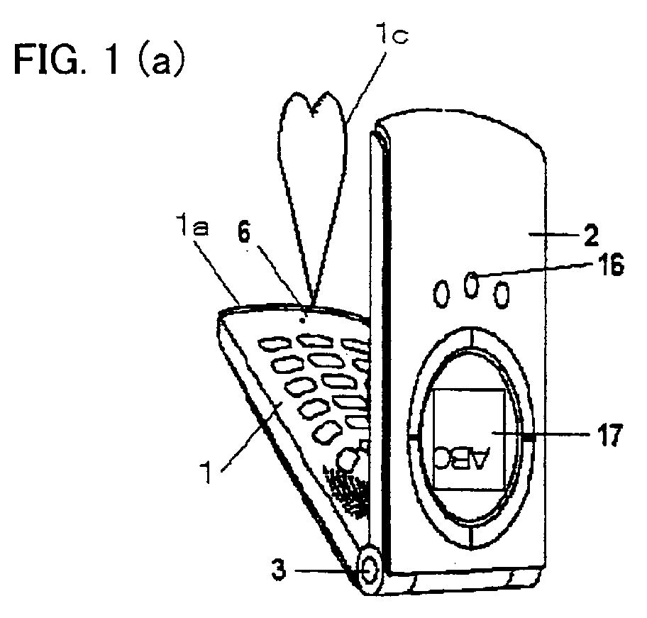
- Fig.1 (a) shows that the electronic device main body is folded at the center.
- Fig.1 (b) shows that the electronic device main body is unfolded.
- Fig.2 (a) also shows that the electronic device main body is folded at the center, but Fig.2 (a) shows a case when the electronic device main body is viewed from the opposite side of Fig.1 (a).
- Fig.2 (b) shows that the electronic device main body is unfolded, but Fig.2 (b) shows a case when the electronic device main body is viewed from the opposite side of the Fig.2 (a).
- the multifunctional mobile electronic device has a mobile phone function and a camera function, and can be used as a mobile phone terminal, which can be brought with the user wherever he or she goes, and also can be used as a camera. Furthermore, the camera function allows a picture image to be taken, and the mobile telephone function allows the picture image thus taken to be transmitted. In addition, the electronic device can also be used as a videophone terminal.
- a reference numeral 1 indicates a rectangle-shaped main body section of the device (first or second member), the main body section 1 being illustrated so as to be longer than is wide in Fig.1 and Fig.2.
- the main body section 1 includes a variety of control circuits and other circuits which carry out the mobile phone function, and further includes a variety of key switches used for operations (later described in detail).
- a reference numeral 2 indicates a cover section (second or first member), and has substantially the same shape as that of the main body section 1.
- the cover section 2 is combined with the main body section 1 via a coupling section 3 so that the sections 1 and 2 pivot around the coupling section 3, thereby constituting the electronic device main body.
- the coupling section 3 is preferably a hinge structure which allows the main body section 1 and the cover section 2 to be folded or unfolded or retained at any angle.
- the electronic device main body can be unfolded up to approximately 180 degree.
- the main body section 1 and the cover section 2 constitute the multifunctional electronic device main body.
- the main body 1 and the cover section 2 have arc-shaped ends on the opposite side of the coupling section 3, respectively.
- the arc-shaped ends realize a lock structure (not shown).
- the lock structure locks the arc-shaped ends when the main body section 1 meets the cover section 2.
- a suspensible string 1b which is used to suspend the multifunctional electronic device from one's neck and also can be used as a mobile phone strap, is provided at the center of the arc-shaped end 1a of the main body section 1. Therefore, when the multifunctional device is suspended from the user's neck, the device becomes a kind of ornament such as a pendant.
- the outer surfaces of the main body section 1 and the cover section 2 are designed and structured to be suitable for an ornament as later described.
- an inputting key switch section (operating section) 4 used to input numeral characters or alphabets
- an operation key group 5 used for a variety of operations
- a microphone 6 used for a voice input when the device is used as a mobile phone
- a speaker 7 used to amplify and reproduce a voice.
- a sideway-position shutter button (first shutter button) 8 is provided on a side surface 52 of the main body section 1.
- the main key 51 first or second shutter button
- the main key 51 is designed to perform as a shutter button for the camera.
- the lens cover 11 is constituted by a substantially circle-shaped thin metal sheet as shown in the figure, and the surface is embedded so as to be in plane with the surface of the main body section 1. In addition, the lens cover 11 is provided so as to rotate around its center part.
- a circle-shaped hollow section 12, used to put the user's finger on it, is provided on the lens cover 11 as shown in the figure 2(b). This structure allows the user to put his or her finger on the circle-shaped hollow section 12, so as to rotate the lens cover 11 with his or her finger.
- an opening is provided in an area corresponding to the area where the lens section 9 of the main camera is placed, and an opening is provided on the lens cover 11 in front of the flashlight 10.
- the multifunctional electronic device may include a detecting means for detecting that the opening of the lens cover 11 is in a position at which the main camera lens section 9 is exposed, so as to carry out the digital still camera mode in response to the detecting means.
- a reference numeral 18 indicates a grip, which makes grasping the multifunctional electronic device easier.
- the cover section 2 includes a main display (second display) 13, an earphone speaker 14, and a sub camera lens section (second image pick-up) 15.
- the main display 13 displays received e-mails, attached picture images and motion pictures when used as a videophone, or a variety of information for the mobile phone operation.
- the earphone speaker 14 is used when the multifunctional electronic device is used as a mobile phone, and the sub camera lens section (second image pick-up) 15 is used as a another camera when the multifunctional electronic device is used as a portable videophone terminal.
- the sub camera lens section 15 is provided in the cover section 2 close to the coupling section 3, but the present invention is not limited to this, i.e., for example, the sub camera lens section 15 may be provided on the inner surface side of the main body section 1 if no space limitations.
- a rectangle-shaped sub display (first display) 17 is provided in a flat area of a frustum-shaped somewhat protuberant section on the outer surface side of the cover section 2 close to the coupling section 3. Furthermore, below the sub display section 17, three buttons 16 are provided along the skirt of the protuberant section. The three buttons 16 are used for operations dealing with information about e-mail of the mobile phone. Note that the three buttons (first shutter button or shutter button for second camera) 16 are also used as a further shutter button. To be specific, the shutter buttons 16 are used when the camera is operated at the lengthways-position.
- the position of the shutter buttons 16 are not limited to the position indicated in the figure, provided that the shutter buttons 16 are close to the sub display section. This is because the user sees the sub display section while he or she is taking a picture image with the device. And other key switches (not shown) for a variety of operations are provided.
- the area where the above-mentioned sub display section 17 displays may be smaller than the area where the main display 13 displays. It is needless to say that the proper size depends on what is to be displayed.
- the sub display section 17 is used to display a calling party's phone number or a calling party's name if the name is stored in a memory.
- the sub display section 17 is used as an electronic finder when the main camera of this electronic device is used as a digital still camera . Furthermore, it goes without saying that a variety of information that the user intends to display can be displayed on the sub display section 17.
- the main display section 13 is designed so that inputted texts are recognized properly and correctly on the display when the multifunctional electronic device is held by the user such that the inputting key switch section 4 is located downward as shown in Fig. 1(b).
- the sub display section 17 is designed such that the coupling section 3 is located above displayed texts that are recognized properly and correctly on the display.
- the above-mentioned main camera functioned as the first camera has preferably two-mega pixels or more, so as to use the multifunctional electronic device as a full-fledged camera.
- around three hundred kilo pixels are enough for the sub camera as the second camera. This is because the sub camera is used for an image pick-up when the multifunctional electronic device of the present invention is used as a mobile phone terminal equipped with a digital camera or used as a mobile videophone terminal.
- a memory is provided in the multifunctional electronic device of the present invention such that picture image information (image data) taken by a camera can be stored in the memory.
- image data is a facial portrait
- the image data is correlated with the identification information of the identical person of the facial portrait such as telephone number.
- the image data stored in the memory is displayed by the sub display section.
- the image data is not limited to a facial portrait, provided that the image data is information, including a facial portrait, which is correlated with a specific identification information.
- Fig. 3 shows that this multifunctional electronic device is folded.
- the device when the device is folded and held such that the coupling section 3 is located upward, the device has a lengthways shape. At that time, texts displayed in the sub display section 17 can be seen properly and correctly. And then, when the device is unfolded by pulling the cover section 2 upward, the main display section 13 comes out on the inner surface side of the cover section 2. And the texts are displayed in the main display section 13 such that the coupling section 3 is located under the texts that are displayed properly and correctly (see Fig.1 (b)). Because of this, the user can read texts displayed in the main display without turning the device around. Therefore the design of this device is highly user-friendly.
- this multifunctional electronic device When this multifunctional electronic device is used as a mobile telephone terminal, as shown in Fig.1 (b), the microphone 6 is to be placed near one's mouth, and the speaker 14 is to be put near the user's ear, while the device is unfolded. By taking such an action, the user can use this multifunctional electronic device as comfortable as when he or she uses a conventional mobile phone terminal. Note that the side of the main body section 1 for the coupling 3 meets the side of the cover section 2 for the coupling 3 when the device is unfolded at its maximum as shown in Fig1 (b).
- This multifunctional electronic device is not only used as a mobile phone terminal, but also can be used seamlessly as a camera and as a videophone.
- Fig. 4 shows how this multifunctional electronic device is used as a still camera.
- the device is folded and held in a sideways manner by holding an arc-shaped edge 18b.
- the main camera lens 9, which is not shown in Fig. 4, is pointed at a subject, and the sub display 17 on the cover section 2 is used as an electronic finder.
- a taper 18a is formed toward the arc-shaped edge 18b of the outer surface of the main body section 1.
- the user puts his or her fingers along the taper 18a and then holds the device by grasping the grip 18 that is projected on the taper 18a, the user can hold the device in a sideways manner. Thereafter, when pushing the sideway-position shutter button 8, a picture image can be taken.
- the main body section 1 is combined with the cover section 2, the camera itself is firmly stable. Also picture images can be taken with less camera shake because this tight camera can be held firmly. Although this is not specially shown in the figure, the camera can be held more stably by putting the user's left hand on the bottom of the device.
- the device starts to perform the camera function as soon as a shutter button of the device is touched, when the multifunctional electronic device is switched on, folded, and in stand-by mode as a mobile phone.
- Fig.5 shows how the device is used as a camera in a lengthwise manner.
- the shutter button 16 that are provided under the sub display section 17, it is possible to stably take a picture while the camera (multifunctional electronic device) is held with one hand.
- Fig.6 shows how the user takes a picture of himself or herself.
- the sub camera lens section 15 provided under the main display section 13 is used.
- the main display section 13 is used as an electronic finder, and the key 51 of the operation key group 5 is used as a shutter button.
- the multifunctional electronic device may be arranged such that the main camera is used and its lens section 9 is selected so as to take a picture of a subject.
- Fig.7 shows an example.
- the lens section 15 for the sub camera is used to take an image.
- the image thus taken is sent to a receiving end, and an image transmitted from the receiving end is displayed on the main display section 13.
- the lens section 15 for the sub camera is provided near the coupling section 3. This allows the lens section 15 for the sub camera to be located close to an eye line of the user watching the main display section 13. Therefore, the user is taken a picture from an optimum angle by the sub camera.
- a speaker 7 amplifies the voice of the receiving end
- a microphone 6 captures the voice of the user and transmits the voice to the receiving end.
- the device may be arranged such that a part of the main display section 13 displays an image which is sent to the receiving end and the user can communicate while monitoring the image on the main display section 13.
- the composite image is made by combining first and second images.
- the first image is obtained by unfolding the electronic device as shown in Fig 1 (b) and Fig 2 (b), by holding it in such a sideway manner as to allow the user's right hand to hold it on the side of the arc-shaped edge 18b in the main body section, and by using the device as the sub camera and taking a picture of the user's own.
- the second image is obtained by taking a picture of an image such as beautiful scenery with the use of the main camera.
- the second image is incorporated into the first image.
- the second image serves as background of the first image.
- the image thus combined may be displayed on a part of the main display section 13.
- the above-mentioned example deals with a case where the lens section 9 for the main camera is provided on the outer surface of the main body section 1 and the sub display section 17 is provided on the outer surface of the cover section 2.
- the present invention is not limited to this. i.e., it may be arranged such that the sub display section 17 is provided on the outer surface of the main body section 1 and the lens section 9 for the main camera is provided on the outer surface of the cover section 2. This arrangement allows the multifunctional electronic device to be a full-fledged still camera.
- the composite image is made by combining first and second images.
- the first image is obtained by unfolding the electronic device with a greater angle than that shown in Fig 1 (a) (for example, by unfolding it with about 90 degree), by holding it in such a vertical manner as to allow the user's right hand to hold it or as to allow the electronic device to be put on a desk, and by taking a picture of the user's own with the lens section 15 for the sub camera.
- the second image is obtained by taking a picture of an image such as beautiful scenery with the use of the lens section 9 for the main camera which is provided on the outer surface of the cover section 2.
- the description deals with a case where the main camera is used as a full-fledged still camera, but the present invention is not limited to this. There is no need to say that a picture image taken by the main camera can be sent to a receiving end by using the mobile phone function. In this example, the size of picture image becomes big, so it is preferable to provide in a camera control circuit some means for changing the picture image size into a proper size for sending via the mobile phone function.
- Fig.8 is a perspective view showing how the multifunctional electronic device is charged.
- a reference numeral 100 is a rectangle-shaped adapter, which can be fitted into and can be removed from a peripheral part of the coupling section 3 of the device via a concave-shaped fitting part 101. Note that the fitting between the two parts becomes firmer when the coupling section 3 and the adapter 100 are magnetically connected.
- An adapter stand 102 is provided at the bottom of this adapter 100, which enables the adapter 100 to stand at a proper angle of 135 degree, for example. And in this example, the adapter stand works as a photo stand; the electronic device fitted into the adapter 100 also stands and sustains at the same angle as the adapter 100 stands.
- the device becomes a photo stand that displays a stand-by picture image when the device is in a mobile phone mode.
- this multifunctional electronic device When this multifunctional electronic device is used as a mobile phone, the multifunctional electronic device is used in a lengthways (vertical) manner. Therefore, a received picture image or a taken picture is displayed so that top or bottom of the picture is directed to the coupling section 3 and the arc-shaped edge. In contrast, when the electronic device is put in a sideways manner as mentioned above, a picture image on the sub display section 17 is rotated at an angle of 90 degree and displayed so that one of the longer sides of the picture image is directed to the top.
- a built-in positioning sensor (not shown), which detects whether the device is in a sideways manner or the device is in a lengthways manner, controls the direction of the picture image displayed in the sub display section 17.
- three-dimensional information can be displayed on the sub display section 17 when a liquid crystal display apparatus, which can select and display two-dimensional information or three-dimensional information, is used for the sub display 17.
- the angle of the adapter stand 102 is adjusted such that the device main body is inclined at an angle which allows the user to view a stereo-image in the best condition.
- Fig. 9 shows a schematic view showing the signal processing of the multifunctional electronic device of the present invention having both a mobile phone function and a digital camera function relating to the present invention. Because the signal processing is not essential matter for the present invention, the details are omitted here.
- a multifunctional electronic device 81 in accordance with the present invention having a mobile phone function and a digital camera function includes a data processor means 88 for entirely controlling operations of this multifunctional electronic device.
- a CPU is included in this data processor means 88.
- An input-output means 75 such as a variety of key switch sections, a microphone for voice input and a speaker for voice output, and
- a memory 72 are connected to the data processor means 88.
- the memory 72 includes (i) a ROM in which an operation control program causing the multifunctional electronic device to function as a digital camera or as a mobile phone having a camera is stored, (ii) a ROM in which a variety of constants and parameters which indicate picture-taking conditions, respectively for the digital camera function, and (iii) a RAM (storage means) which is used as working area when a program is run.
- the above-mentioned data processor means 88 carries out overall control over the multifunctional electronic device 81 of the present invention such as (a) a sampling timing control of the image data taken by the digital camera or the mobile phone having a camera, (b) an exposure control including settings of aperture diaphragm and shutter speed, (c) a focusing control, (d) a zoom control, (e) a setting of white balance, (f) a control of image data log, (g) a communication control, (h) a display control, (i) a processing for converting the number of pixels of an image data, (j) a variety of conversion processing of added data, and (k) setting and releasing of mode for saving the power consumption .
- a sampling timing control of the image data taken by the digital camera or the mobile phone having a camera an exposure control including settings of aperture diaphragm and shutter speed, (c) a focusing control, (d) a zoom control, (e) a setting of white balance, (f) a control of image data
- the multifunctional electronic device 81 of the present invention further includes a main display section 87, a sub display section 82, a digital camera 83 including main and sub cameras, image data processor means 84, a frame memory 85 for temporarily storing image data, a D/A converter 86, data compressor and decompressor means 89, a recording medium interface 76, and a recording medium 77.
- the multifunctional electronic device 81 further includes transmission and receiving means 73 required for the mobile phone function, a communication connecter 71, and an antenna 74.
- the image data processor means 84 carries out operations such as changing of the number of the pixels, a sharpness offset, gamma correction, a contrast correction, a white balance compensation. An image data outputted from the image data processor means 84 is temporarily stored in the frame memory.
- the compressor and decompressor means 89 carries out a control of compressing of data such as image data in accordance with a technique such as JPEG or MPEG files, and carries out a control of decompressing of the compressed data by the command of the data compressor and decompressor means 89.
- This allows large volumetric data such as image data to send and receive efficiently.
- the data recording medium interface 76 is provided for connecting or disconnecting the recording medium 77 such as (a) a semiconductor such as a variety of memory cards or an MO, (b) a magnetic recorder, or (c) a magneto-optical recorder.
- the transmission and receiving means 73 is commanded by the data processor means 88 to encode and complexate data such as image data and directories, to put the data on carrier wave, and to send and receive the data via the antenna 74.
- the communication connecter 71 is provided for wired-line communication of information such as image data. Besides, the communication connector 71 can send image files or data stored in RAM or ROM in the memory 72 or the frame memory 85 to a device which includes a similar communication connector, and can save data transmitted from a receiving end in the variety of recording media. Note that an optical cable can be used for the connection between the communication connects. In this case, the signal should be converted into an optical signal.
- the main camera and the sub camera are arranged in parallel in the digital camera 83.
- the user can choose a suitable camera of the two for each occasion.
- the main camera can operate immediately when the multifunctional electronic device of the present invention is folded and in the stand-by mode of the mobile phone. This allows the user to release the shutter immediately, when the sideway-position shutter button 8 is pressed.
- a shutter button can be assigned to a variety of key switches. However, as explained in the embodiment, shutter buttons are assigned to the sideway-position shutter button 8, the lengthways-position shutter button 16, and the key 51 of the operation key group 5.
- the digital camera 83 includes (a) a photoelectric conversion device such as CCD which carries out photoelectric conversion by forming an image of the subject on a light receiving surface and which outputs the converted result as an image data, (b) focusing means for forming the image of the subject on the light receiving surface, (c) an aperture mechanism for adjustment of light exposure, (d) shutter speed adjuster means for adjustment of an exposure time, and (e) a zoom mechanism for adjustment of a field angle.
- a photoelectric conversion device such as CCD which carries out photoelectric conversion by forming an image of the subject on a light receiving surface and which outputs the converted result as an image data
- focusing means for forming the image of the subject on the light receiving surface
- an aperture mechanism for adjustment of light exposure e.g., an aperture mechanism for adjustment of light exposure
- shutter speed adjuster means for adjustment of an exposure time
- a zoom mechanism for adjustment of a field angle.
- All of the devices and means (a) through (e) are controlled by the data processor means 88. Also, when the multifunctional electronic device is used as a mobile phone terminal, voice input and voice output are carried out by the input-output means 75.
- the embodiment deals with a multifunctional electronic device having both a still camera function and a mobile phone function, but the present invention is not limited to this.
- the multifunctional electronic device may be arranged so as to include a personal computer function, a calculator function, a PDA function, an e-mail function, or a translation function, instead of the mobile phone function.
- a personal computer function e.g., a personal computer function
- a calculator function e.g., a calculator function
- PDA function e.g., a PDA function
- e-mail function e.g., a e-mail function
- translation function instead of the mobile phone function.
- at least one of the functions may be included.
- the present invention may be comfortably used as an ordinary multifunctional electronic device, such as a mobile phone, having displays section and inputting key switch section when the multifunctional electronic device is unfolded.
- the multifunctional electronic device may be also used as seamless as a full-fledged still camera when the multifunctional electronic device is folded. In this case, it is possible to take a picture with less camera blurring.
- the sub display section it is possible in the sub display section to see information relating to the multifunctional electronic device, while the multifunctional electronic device is folded. Therefore, when information is obtained via communication - for example, when receiving a telephone call - the user can easily know who called by only seeing the sub display section. In this case, when information such as a face of a sending end was stored in a memory of the main body of the multifunctional electronic device, it is possible to display the information such as the face upon receipt of a telephone calling, thereby increasing further amusement during the use of the multifunctional electronic device.
- the multifunctional mobile electronic device when holding the multifunctional mobile electronic device such that its coupling section directs upward while the multifunctional mobile electronic device is folded, it is possible to directly read texts from the sub display section. And, when the multifunctional mobile electronic device is kept to be held like that, it is possible to directly read texts from the main display section by unfolding the cover section upward, thereby ensuring that the user can comfortably use the multifunctional mobile electronic device.
- the multifunctional electronic device of the present invention When the multifunctional electronic device of the present invention is used as a videophone, it is possible for a sending end (a) to transmit its image to an receiving end while the sending end sees an image from the receiving end, and (b) to listen to the receiving end after amplifying a voice from the receiving end, thereby ensuring that the user can comfortably use the multifunctional mobile electronic device.
- the multifunctional electronic device becomes more user-friendly because shutter buttons provided for the camera are provided in various areas. This allows the user to take a variety of pictures in accordance with how the camera is used, thereby improving the operationality of the multifunctional electronic device.
- the multifunctional mobile electronic device relating to the present invention includes a device main body that is combined by a main body section and a cover section via a coupling section such that the main body and the cover section can be folded.
- One of inner surfaces (surfaces of the main body section and the cover body meet each other when the electronic device is folded) of the main body section and the cover section is provided with an input key section including numeral keys, the other of the inner surfaces is provided with a main display section.
- the multifunctional mobile electronic device further includes (i) a lens section, provided for a first camera, provided in one of outer surfaces (surfaces of the main body and the cover which are exposed to outside when the electronic device is folded) of the main body section and the cover section, (ii) a sub display section, that serves as a finder of the first camera, provided in the other of the outer surfaces, and (iii) a shutter button, provided for the first camera, provided in a side surface part of the device main body.
- a lens section provided for a first camera, provided in one of outer surfaces (surfaces of the main body and the cover which are exposed to outside when the electronic device is folded) of the main body section and the cover section
- a sub display section that serves as a finder of the first camera, provided in the other of the outer surfaces
- a shutter button provided for the first camera, provided in a side surface part of the device main body.
- the multifunctional mobile electronic device in accordance with the present invention is constituted so that the main display section displays information such that the coupling section is downward, and the sub display section displays information such that the coupling section is upward.
- the present invention it is possible to display, on the sub display section that serves as a finder, information of the electronic device such as a telephone terminal. This allows identification information of a sending end in an email to be displayed on the sub display section, even when the cover section is folded.
- the device main body has a rectangular shape and a shutter button provided for a camera is provided. This allows the multifunctional mobile electronic device to be used as a full-fledged still camera when the device main body is hold in an oblong manner.
- a sub camera and a speaker are provided on an inner surface side of the electronic device main body which is kept to be unfolded.
- the multifunctional mobile electronic device when used as a videophone, it is possible to transmit an image of a sending end that has been taken while viewing an image (face image) on the main display section that has been transmitted from a receiving end and it is also possible to listen to the receiving end.
- a shutter button provided for the sub camera is provided on the inner surface side of the electronic device main body that is kept to be unfolded, and (b) the third shutter button is provided near the sub display section.
- this arrangement allows the main camera to take a picture by using the main display section that serves as a finder of the main camera. Furthermore, when a shutter button provided for the main camera is provided in plane with the sub display section, it is possible to use the multifunctional mobile electronic device as a vertical still camera. Further, it is possible to use the main display section simultaneously in a various manner, for example, to use for superimposing of the image from the camera and the image from the sub camera.
- the sub display section displays identification information of a sending end that has transmitted a communication request
- the electronic device stores information such as an image related to the identification information, and display the related information on the sub display when the sending end corresponds to the identification information.
- the foregoing embodiment deals with the arrangement in which the sideways-position shutter 8 is provided in the side part 52 of the main body section 1, but the present invention is not limited to this.
- the sideways-position shutter 8 may be provided in a side part of the main body section other than the side part 52.
- the sideways-position shutter 8 may be provided in the cover section 2, instead of placing the sideway-position shutter 8 in the main body section 1.
- the foregoing embodiment deals with the arrangement in which the cover section 2 is provided with the shutter button 16, but the present invention is not limited to this.
- the shutter button 16 may be provided in a surface where the lens section 9 in the main body section 1.
- the foregoing embodiment deals with the arrangement in which the main body section 1 is provided with the shutter button 51 provided for the sub camera, the present invention is not limited to this.
- the shutter button 51 may be provided in an inner surface of the cover section 2, for example on a side of the lens section 15 for the sub camera.
- the foregoing embodiment deals with the arrangement in which the cover section 2 is provided with the shutter button 15 provided for the sub camera, but the present invention is not limited to this.
- the shutter button 15 may be provided in an inner surface of the main body section 1.
- first and second members can be folded via a coupling section.
- the first member includes a first image pick-up section provided in a surface on an opposite side of an opposed surface which faces the second member when the electronic device is folded.
- the second member includes a first display section, which displays at least an image taken by the first image-pick up section, provided in a surface on an opposite side of an opposed surface which faces the first member when the electronic device is folded.
- the electronic device includes (ii) an operation section of key-switch type provided in an opposed surface of the first member or the second member, and (ii) a second display section which displays at least data supplied via the operation section in the other of the opposed surfaces.
- the electronic device includes a first shutter button provided for the first image pick-up section provided in an outer surface of the electronic device when the electronic device is folded.
- the electronic device includes the first shutter button (i) provided in a surface which is perpendicular to the opposed surface of the first member or (ii) provided in a surface which is perpendicular to the opposed surface of the second member.
- the electronic device includes the first shutter button (i) provided in the surface on the opposite side of the opposed surface of the first member or (ii) provided in the surface on the opposite side of the opposed surface of the second member.
- the electronic device includes a second image pick-up section provided in an opposed surface of the first or second member.
- the electronic device includes a second image pick-up section provided in an opposed surface of the first or second members.
- the electronic device has a communication function.
- the electronic device has a mobile phone function.
Abstract
Description
- The present invention relates to a multifunctional mobile electronic device having (a) a digital camera function, and (b) an electronic device function that is carried out by an inputting section via which at least numeric data can be inputted and by a main display which displays an inputted content. More particularly, the present invention relates to a multifunctional mobile device including (i) a camera, having at least CCD, which converts a picture image into electric signals, and (ii) a display section composed of such as a liquid crystal display which can display picture image signals from the camera, externally inputted image signals, or other image signals, preferably with a PDA function such as a scheduler function.
- Recently, a digital camera using such as a CCD has become smaller and its performance has been highly improved. On this account, a mobile phone equipped with a digital camera has been prevailed. By using the mobile phone equipped with a digital camera, a picture image taken by the camera can be sent to a called party via phone line. Also the mobile phone can be used as a videophone by which the calling party and the called party can see each other's face on a display of each phone while chatting. Furthermore, the mobile phone can be used as a digital still camera by storing picture images in its memory.
- This kind of conventional mobile phone is disclosed in Japanese Unexamined Patent Publication No.10-257460 (published on September 25, 1998), for example.
- Fig.10 shows the conventional mobile phone. Here, Fig.10 (a) is an external view illustrating the mobile phone when the mobile phone is used as a still camera. Fig.10 (b) is an external view illustrating the mobile phone when the mobile phone is used as a mobile phone or a mobile videophone (hereinafter referred to as mobile phone). Fig.10 (c) is an external view of the mobile phone when the mobile phone is folded.
- In Fig.10, a
reference numeral 91 is a cabinet of the camera section. Acamera lens 93 is placed on a surface of the camera device. Areference numeral 92 is a cabinet of the display section. When the mobile phone is used as a mobile phone, as shown in Fig.10 (b), adisplay section 94 composed of members such as a liquid crystal panel is placed on the side where thecamera lens 93 is placed. The cabinet of thecamera section 91 is combined with the cabinet of thedisplay section 92 by thebond axes 90 so that the mobile phone can freely pivot. When the mobile phone is folded so that thecamera lens 93 faces thedisplay device 94, the mobile phone is in a foldaway state as shown in Fig. 10 (c). On the other hand, when the mobile phone is folded conversely, the mobile phone is in a still camera mode as shown in Fig 10 (c). - Fig. 11 shows details of the
bond axes 90. As shown in Fig. 11, the cabinet of thecamera section 91 includes cylindrical bond axes (95, 96), and the cabinet of thedisplay section 92 includes semi-cylindrical bond axis bearings (97, 98). The bond axes (95, 96) and the bond axes bearings (97, 98) are provided so as to be incorporable in each other. - Here, as shown in Fig.11 (a), the mobile phone is used as a still camera when the
bond axis 95 is combined with the bond axis bearing 98. On the other hand, Fig 11 (b) shows that the mobile phone is used as a mobile phone when thebond axis 96 is combined with the bond axis bearing 97 and when thebond axis 95 is incorporated in the bond axis bearing 98. Furthermore, Fig 11 (c) shows that the mobile phone is folded away when thecylindrical bond axis 96 is incorporated in the semi-cylindrical bond axis bearing 97. - It is not clearly indicated in the figures, but a signal-processing section for the camera section is contained in the cabinet of the
camera section 91, and a signal-processing section for the display section is contained in the cabinet of thedisplay section 92. In addition, a variety of signal processing sections for communication and a power source section are properly contained in the above-mentioned cabinets. Power supply means and signal transmission means are provided between the cabinet of thecamera section 91 and the cabinet of thedisplay section 92. - In this conventional technology, when the mobile phone is used as a mobile phone or a mobile videophone, the cabinet of the
camera device 91 and the cabinet of thedisplay device 92 are pivoted in a lengthwise direction, i.e., so that thecamera lens 93 and thedisplay device 94 are aligned in a single surface. On the other hand, when the mobile phone is used as a still camera, the mobile phone is folded so that both thedisplay section 94 and thecamera lens 93 face outside. - Note that it is not clearly indicated, but there is no need to say that properly equipped microphone and speaker are used when the mobile phone is used as a mobile phone or a mobile videophone. Note also that when the mobile phone is used as a mobile phone or mobile videophone, a dial indicating is carried out on the
display section 92. Thisdisplay section 92 is to be used as a touch panel, so as to operate a dial control. - According to the conventional technology mentioned above, a small mobile device having (a) a mobile phone function or a mobile videophone function and (b) a digital still camera function can be remarkably compacted. This is because the mobile phone is designed to be folded so that the camera section meets the display section.
- However, dial buttons displayed and partially occupied on some parts of the
display section 94 are used to input a telephone number in order to make a phone call. On this account, it is not only difficult to recognize the inputted content but also it is required to use a thin pencil-shaped indicator to operate a dial control. Therefore, the operation is not necessarily easy. - Furthermore, the
display section 94 is easily scratched. This is because thedisplay section 94, which becomes an input section when the mobile phone is used as a mobile phone, is always exposed to outside when the mobile phone is used as a digital still camera. Also, a keyboard of key switch type cannot be equipped on the display section. - In addition, the cabinet of the
display section 92 and the cabinet of thecamera section 91 can pivot in the range of 360 degree (in other word, one of thedisplay device 92 and the cabinet of thecamera device 91 can pivot with respect to the other in the range of 360 degree). This causes structure of this pivoting part to become complicated. Therefore, there are problems about the cost and the reliability of the product as well. - Also, in this conventional art, when the folded mobile phone is rung, it is required to unfold the mobile phone to see the display section. Without the unfolding, the called party cannot know who called. This raises a problem about usability.
- In addition, when the mobile phone is used as a digital still camera, it is required to carry out a 360°-pivot with respect to the cabinet of the
display section 92 and the cabinet of thecamera section 91. This is bothering and takes time to release the shutter. This is another problem. - On the other hand, there is also a conventional camera-equipped mobile phone having a sub display section on which a picture image that has been picturized by the camera is displayed, the sub display section being provided on a plane in which a cover member to which the camera is attached is provided. Even though the user can take a picture of himself or herself easily with this mobile phone, it is difficult to take a picture of other subjects. Therefore it is difficult for this mobile phone to be used as a still camera. Furthermore, a prescribed procedure is required for changing to a camera mod from a mobile phone mode in the middle of using the mobile phone in the mobile phone mode. This is because the camera-equipped mobile phone is usually used as a mobile phone. Therefore there is a problem that it takes too much time to take a picture when the user wants to take a picture immediately.
- The present invention is made in light of the foregoing problems. An object of the present invention is to provide a multifunctional mobile electronic device which can be easily operated when used as a digital still camera, and to which a keystroke operation can be carried out with ease when used as a different electronic device. Specifically, an object of the present invention is to provide a multifunctional mobile electronic device, i.e., a full-fledged still camera that also can be used as a mobile phone.
- A multifunctional electronic device in accordance with the present invention is made in order to achieve the objects. The multifunctional mobile electronic device includes a device main body that is combined by a main body section and a cover section via a coupling section such that the main body and the cover section can be folded. One of inner surfaces (surfaces of the main body section and the cover body meeting each other when the electronic device is folded) of the main body section and the cover section is provided with an input key section including numeral keys, and the other of the inner surfaces is provided with a main display section. The multifunctional electronic device further includes (i) a lens section, provided for a first camera, provided in one of outer surfaces (surfaces of the main body and the cover body which are exposed to outside when the electronic device is folded) of the main body section and the cover section, (ii) a sub display section, that serves as a finder of the first camera, provided in the other of the outer surfaces, (iii) a shutter button, provided for the first camera, provided in a side surface part of the device main body.
- In the arrangement, it may be arranged such that the lens section for the camera and the sub display section are provided contrary to the above-mentioned arrangement, i.e., the lens section for the camera is provided in the outer surface of the cover section and the sub display section is provided in the main body section.
- With the arrangement, the multifunctional electronic device can be used as a still camera while the multifunctional electronic device is folded. Furthermore, the multifunctional electronic device can be used as an electronic device having an easily operated key switch keyboard and the main display section such as a telephone terminal, when opening the cover section.
- Accordingly, a multifunctional mobile electronic device that can be easily used as a still camera and that also works effectively as an electronic device such as a telephone is obtained. Especially, because the input section and the display section are separately provided in the cover section and the main body section, both the input section and the display section can be bigger.
- Also, there is an advantage that designing machine becomes easier when the camera is provided in the main body section because a control circuit for the mobile phone terminal and a control circuit for the still camera can be provided all together in the main body section.
- Also, in order to achieve the object, an electronic device in which first and second members can be folded via a coupling section, is characterized in that (a) the first member includes a lens section for a main camera provided in a surface on an opposite side of an opposed surface which faces the second member when the electronic device is folded, and (b) the second member includes a sub display section, that displays at least an image taken by the lens section, provided in a surface on an opposite side of an opposed surface which faces the first member when the electronic device is folded.
- For a fuller understanding of the nature and advantages of the invention, reference should be made to the ensuing detailed description taken in conjunction with the accompanying drawings.
-
- Fig.1 (a) is a perspective illustration showing a state in which a cover is partially unfold in a multifunctional electronic device in accordance with an embodiment of the present invention, and Fig.1 (b) is a perspective illustration showing a state in which the cover of the multifunctional electronic device is completely unfolded.
- Fig.2 (a) is a perspective illustration of the multifunctional electronic device when viewing from different point from Fig.1 (a), and Fig.2 (b) shows the other side of the multifunctional electronic device shown in Fig.1 (b).
- Fig.3 is a perspective illustration showing a state in which the multifunctional electronic device of the present invention is folded.
- Fig.4 is an explanatory view showing a case where the multifunctional electronic device of the present invention is used as a full-fledged camera.
- Fig.5 is an explanatory view showing a case where the multifunctional electronic device of the present invention is used as a lengthways-position camera.
- Fig.6 is an explanatory view showing how the multifunctional electronic device of the present invention is used when the user takes a picture of himself or herself.
- Fig.7 is an explanatory view showing how the multifunctional electronic device of the present invention is used differently, and shows how the user takes a picture of a subject with the multifunctional electronic device unfolded.
- Fig.8 is an explanatory view showing how the multifunctional electronic device of the present invention is used.
- Fig.9 is a block diagram schematically showing a flow of a signal processing of the multifunctional electronic device.
- Fig. 10 (a) is a perspective illustration showing that a conventional compact electronic device is folded so as to be used as a camera. Fig.10 (b) is a perspective illustration showing a case where the compact electronic device is used as a mobile phone. Fig.10 (c) is a perspective illustration of the compact electronic device when folded away.
- Fig.11 (a), (b), (c) are lateral view illustrations which correspond respectively to the figure 10 (a), (b), (c).
-
- Thereinafter, a preferred embodiment of the present invention is explained in detail by using figures. Fig.1 and Fig.2 are overview illustrations of a multifunctional mobile electronic device in accordance with an embodiment of the present invention.
- Fig.1 (a) shows that the electronic device main body is folded at the center. Fig.1 (b) shows that the electronic device main body is unfolded. Fig.2 (a) also shows that the electronic device main body is folded at the center, but Fig.2 (a) shows a case when the electronic device main body is viewed from the opposite side of Fig.1 (a). Fig.2 (b) shows that the electronic device main body is unfolded, but Fig.2 (b) shows a case when the electronic device main body is viewed from the opposite side of the Fig.2 (a).
- The multifunctional mobile electronic device has a mobile phone function and a camera function, and can be used as a mobile phone terminal, which can be brought with the user wherever he or she goes, and also can be used as a camera. Furthermore, the camera function allows a picture image to be taken, and the mobile telephone function allows the picture image thus taken to be transmitted. In addition, the electronic device can also be used as a videophone terminal.
- See Fig.1 and Fig.2. A
reference numeral 1 indicates a rectangle-shaped main body section of the device (first or second member), themain body section 1 being illustrated so as to be longer than is wide in Fig.1 and Fig.2. Themain body section 1 includes a variety of control circuits and other circuits which carry out the mobile phone function, and further includes a variety of key switches used for operations (later described in detail). Areference numeral 2 indicates a cover section (second or first member), and has substantially the same shape as that of themain body section 1. Thecover section 2 is combined with themain body section 1 via acoupling section 3 so that thesections coupling section 3, thereby constituting the electronic device main body. Thecoupling section 3 is preferably a hinge structure which allows themain body section 1 and thecover section 2 to be folded or unfolded or retained at any angle. The electronic device main body can be unfolded up to approximately 180 degree. - Then, the
main body section 1 and thecover section 2 constitute the multifunctional electronic device main body. - The
main body 1 and thecover section 2 have arc-shaped ends on the opposite side of thecoupling section 3, respectively. The arc-shaped ends realize a lock structure (not shown). The lock structure locks the arc-shaped ends when themain body section 1 meets thecover section 2. - A suspensible string 1b, which is used to suspend the multifunctional electronic device from one's neck and also can be used as a mobile phone strap, is provided at the center of the arc-shaped
end 1a of themain body section 1. Therefore, when the multifunctional device is suspended from the user's neck, the device becomes a kind of ornament such as a pendant. - Hence, the outer surfaces of the
main body section 1 and thecover section 2 are designed and structured to be suitable for an ornament as later described. - On an inner surface of the
main body 1, there are provided an inputting key switch section (operating section) 4 used to input numeral characters or alphabets, an operationkey group 5 used for a variety of operations, amicrophone 6 used for a voice input when the device is used as a mobile phone, and aspeaker 7 used to amplify and reproduce a voice. Further, a sideway-position shutter button (first shutter button) 8 is provided on aside surface 52 of themain body section 1. - Furthermore, as shown in Fig.2 (a), there are provided a lens section (first image pick-up section) 9 for a main camera (first camera), a
flashlight 10, and arotary lens cover 11 which protects thelens section 9, provided for the main camera, at the external surface of the main body. In addition, in the present embodiment, the main key 51 (first or second shutter button), which is one of the operationkey group 5, is designed to perform as a shutter button for the camera. - The
lens cover 11 is constituted by a substantially circle-shaped thin metal sheet as shown in the figure, and the surface is embedded so as to be in plane with the surface of themain body section 1. In addition, thelens cover 11 is provided so as to rotate around its center part. A circle-shapedhollow section 12, used to put the user's finger on it, is provided on thelens cover 11 as shown in the figure 2(b). This structure allows the user to put his or her finger on the circle-shapedhollow section 12, so as to rotate thelens cover 11 with his or her finger. - On the
lens cover 11, an opening is provided in an area corresponding to the area where thelens section 9 of the main camera is placed, and an opening is provided on thelens cover 11 in front of theflashlight 10. When the multifunctional electronic device is used as a camera, thelens cover 11 is rotated so that the openings correspond to the maincamera lens section 9 andflashlight 10, respectively. Besides, by rotating thelens cover 11 up to a predetermined position, it is possible to cover the maincamera lens section 9 and theflashlight 10, respectively, when the multifunctional electronic device is not used as a camera. - Note that the rotation of the
lens cover 11 may be controlled as follows. Namely, the multifunctional electronic device may include a detecting means for detecting that the opening of thelens cover 11 is in a position at which the maincamera lens section 9 is exposed, so as to carry out the digital still camera mode in response to the detecting means. - A
reference numeral 18 indicates a grip, which makes grasping the multifunctional electronic device easier. When providing the maincamera lens section 9 in an area corresponding to thecoupling section 3, it is possible to contain the main camera in thecoupling section 3. - On the inner surface side, the
cover section 2 includes a main display (second display) 13, anearphone speaker 14, and a sub camera lens section (second image pick-up) 15. Themain display 13 displays received e-mails, attached picture images and motion pictures when used as a videophone, or a variety of information for the mobile phone operation. Theearphone speaker 14 is used when the multifunctional electronic device is used as a mobile phone, and the sub camera lens section (second image pick-up) 15 is used as a another camera when the multifunctional electronic device is used as a portable videophone terminal. - In this example, the sub
camera lens section 15 is provided in thecover section 2 close to thecoupling section 3, but the present invention is not limited to this, i.e., for example, the subcamera lens section 15 may be provided on the inner surface side of themain body section 1 if no space limitations. - There is provided another display section on the outer surface of the covering
body 2. A rectangle-shaped sub display (first display) 17 is provided in a flat area of a frustum-shaped somewhat protuberant section on the outer surface side of thecover section 2 close to thecoupling section 3. Furthermore, below thesub display section 17, threebuttons 16 are provided along the skirt of the protuberant section. The threebuttons 16 are used for operations dealing with information about e-mail of the mobile phone. Note that the three buttons (first shutter button or shutter button for second camera) 16 are also used as a further shutter button. To be specific, theshutter buttons 16 are used when the camera is operated at the lengthways-position. - Note that the position of the
shutter buttons 16 are not limited to the position indicated in the figure, provided that theshutter buttons 16 are close to the sub display section. This is because the user sees the sub display section while he or she is taking a picture image with the device. And other key switches (not shown) for a variety of operations are provided. - The area where the above-mentioned
sub display section 17 displays may be smaller than the area where themain display 13 displays. It is needless to say that the proper size depends on what is to be displayed. For example, in the stand-by mode in which the multifunctional mobile electronic device of the present invention is folded so as to be used as a mobile phone terminal, thesub display section 17 is used to display a calling party's phone number or a calling party's name if the name is stored in a memory. - Also, the
sub display section 17 is used as an electronic finder when the main camera of this electronic device is used as a digital still camera . Furthermore, it goes without saying that a variety of information that the user intends to display can be displayed on thesub display section 17. - The
main display section 13 is designed so that inputted texts are recognized properly and correctly on the display when the multifunctional electronic device is held by the user such that the inputtingkey switch section 4 is located downward as shown in Fig. 1(b). Thesub display section 17 is designed such that thecoupling section 3 is located above displayed texts that are recognized properly and correctly on the display. - The above-mentioned main camera functioned as the first camera has preferably two-mega pixels or more, so as to use the multifunctional electronic device as a full-fledged camera. On the other hand, around three hundred kilo pixels are enough for the sub camera as the second camera. This is because the sub camera is used for an image pick-up when the multifunctional electronic device of the present invention is used as a mobile phone terminal equipped with a digital camera or used as a mobile videophone terminal.
- A memory is provided in the multifunctional electronic device of the present invention such that picture image information (image data) taken by a camera can be stored in the memory. When the image data is a facial portrait, for example, the image data is correlated with the identification information of the identical person of the facial portrait such as telephone number. Then, when receiving a call from the identical person having the telephone number, the image data stored in the memory is displayed by the sub display section. Note that the image data is not limited to a facial portrait, provided that the image data is information, including a facial portrait, which is correlated with a specific identification information.
- Fig. 3 shows that this multifunctional electronic device is folded. As shown in Fig. 3, when the device is folded and held such that the
coupling section 3 is located upward, the device has a lengthways shape. At that time, texts displayed in thesub display section 17 can be seen properly and correctly. And then, when the device is unfolded by pulling thecover section 2 upward, themain display section 13 comes out on the inner surface side of thecover section 2. And the texts are displayed in themain display section 13 such that thecoupling section 3 is located under the texts that are displayed properly and correctly (see Fig.1 (b)). Because of this, the user can read texts displayed in the main display without turning the device around. Therefore the design of this device is highly user-friendly. - When this multifunctional electronic device is used as a mobile telephone terminal, as shown in Fig.1 (b), the
microphone 6 is to be placed near one's mouth, and thespeaker 14 is to be put near the user's ear, while the device is unfolded. By taking such an action, the user can use this multifunctional electronic device as comfortable as when he or she uses a conventional mobile phone terminal. Note that the side of themain body section 1 for thecoupling 3 meets the side of thecover section 2 for thecoupling 3 when the device is unfolded at its maximum as shown in Fig1 (b). - This multifunctional electronic device is not only used as a mobile phone terminal, but also can be used seamlessly as a camera and as a videophone.
- The following description deals with (a) how this multifunctional electronic device is used as a camera with reference to Fig. 4, Fig. 5, Fig. 6, and Fig. 7 and (b) how this multifunctional electronic device is used as a videophone.
- Fig. 4 shows how this multifunctional electronic device is used as a still camera. In Fig. 4, the device is folded and held in a sideways manner by holding an arc-shaped
edge 18b. Themain camera lens 9, which is not shown in Fig. 4, is pointed at a subject, and thesub display 17 on thecover section 2 is used as an electronic finder. - Furthermore, a taper 18a is formed toward the arc-shaped
edge 18b of the outer surface of themain body section 1. When the user puts his or her fingers along the taper 18a and then holds the device by grasping thegrip 18 that is projected on the taper 18a, the user can hold the device in a sideways manner. Thereafter, when pushing the sideway-position shutter button 8, a picture image can be taken. In addition, because themain body section 1 is combined with thecover section 2, the camera itself is firmly stable. Also picture images can be taken with less camera shake because this tight camera can be held firmly. Although this is not specially shown in the figure, the camera can be held more stably by putting the user's left hand on the bottom of the device. - It is preferable that the device starts to perform the camera function as soon as a shutter button of the device is touched, when the multifunctional electronic device is switched on, folded, and in stand-by mode as a mobile phone. This greatly increases the user-friendliness because a picture can be taken even when the user intends to take a photo in an instant. This is realized by the following arrangement. For example, when the user presses the
shutter button 8 and the device detects that theshutter button 8 is pressed, (a) the device changes the mobile phone mode to the still camera mode, and (b) a picture is taken under the conditions at the time and its image information is stored. - Fig.5 shows how the device is used as a camera in a lengthwise manner. In this case, when using the
shutter button 16 that are provided under thesub display section 17, it is possible to stably take a picture while the camera (multifunctional electronic device) is held with one hand. - Fig.6 shows how the user takes a picture of himself or herself. In this case, the sub
camera lens section 15 provided under themain display section 13 is used. Themain display section 13 is used as an electronic finder, and the key 51 of the operationkey group 5 is used as a shutter button. - In this case, there is no need to say that the multifunctional electronic device may be arranged such that the main camera is used and its
lens section 9 is selected so as to take a picture of a subject. Fig.7 shows an example. - When this multifunctional electronic device is used as a videophone terminal, the
lens section 15 for the sub camera is used to take an image. The image thus taken is sent to a receiving end, and an image transmitted from the receiving end is displayed on themain display section 13. In this case, thelens section 15 for the sub camera is provided near thecoupling section 3. This allows thelens section 15 for the sub camera to be located close to an eye line of the user watching themain display section 13. Therefore, the user is taken a picture from an optimum angle by the sub camera. - In the meantime, a
speaker 7 amplifies the voice of the receiving end, and amicrophone 6 captures the voice of the user and transmits the voice to the receiving end. In this case, the device may be arranged such that a part of themain display section 13 displays an image which is sent to the receiving end and the user can communicate while monitoring the image on themain display section 13. - In the meantime, it is possible for the user to use a composite image and transmit it to a receiving end. The composite image is made by combining first and second images. The first image is obtained by unfolding the electronic device as shown in Fig 1 (b) and Fig 2 (b), by holding it in such a sideway manner as to allow the user's right hand to hold it on the side of the arc-shaped
edge 18b in the main body section, and by using the device as the sub camera and taking a picture of the user's own. The second image is obtained by taking a picture of an image such as beautiful scenery with the use of the main camera. The second image is incorporated into the first image. The second image serves as background of the first image. The image thus combined may be displayed on a part of themain display section 13. - The above-mentioned example deals with a case where the
lens section 9 for the main camera is provided on the outer surface of themain body section 1 and thesub display section 17 is provided on the outer surface of thecover section 2. However, the present invention is not limited to this. i.e., it may be arranged such that thesub display section 17 is provided on the outer surface of themain body section 1 and thelens section 9 for the main camera is provided on the outer surface of thecover section 2. This arrangement allows the multifunctional electronic device to be a full-fledged still camera. - In this arrangement, it is also possible to obtain a composite image similar to the foregoing arrangement. Namely, the composite image is made by combining first and second images. The first image is obtained by unfolding the electronic device with a greater angle than that shown in Fig 1 (a) (for example, by unfolding it with about 90 degree), by holding it in such a vertical manner as to allow the user's right hand to hold it or as to allow the electronic device to be put on a desk, and by taking a picture of the user's own with the
lens section 15 for the sub camera. The second image is obtained by taking a picture of an image such as beautiful scenery with the use of thelens section 9 for the main camera which is provided on the outer surface of thecover section 2. - The description deals with a case where the main camera is used as a full-fledged still camera, but the present invention is not limited to this. There is no need to say that a picture image taken by the main camera can be sent to a receiving end by using the mobile phone function. In this example, the size of picture image becomes big, so it is preferable to provide in a camera control circuit some means for changing the picture image size into a proper size for sending via the mobile phone function.
- Fig.8 is a perspective view showing how the multifunctional electronic device is charged. As shown in the figure, a
reference numeral 100 is a rectangle-shaped adapter, which can be fitted into and can be removed from a peripheral part of thecoupling section 3 of the device via a concave-shapedfitting part 101. Note that the fitting between the two parts becomes firmer when thecoupling section 3 and theadapter 100 are magnetically connected. - An
adapter stand 102 is provided at the bottom of thisadapter 100, which enables theadapter 100 to stand at a proper angle of 135 degree, for example. And in this example, the adapter stand works as a photo stand; the electronic device fitted into theadapter 100 also stands and sustains at the same angle as theadapter 100 stands. - Because the
sub display section 17 can be seen from the front in this state, the device becomes a photo stand that displays a stand-by picture image when the device is in a mobile phone mode. - When this multifunctional electronic device is used as a mobile phone, the multifunctional electronic device is used in a lengthways (vertical) manner. Therefore, a received picture image or a taken picture is displayed so that top or bottom of the picture is directed to the
coupling section 3 and the arc-shaped edge. In contrast, when the electronic device is put in a sideways manner as mentioned above, a picture image on thesub display section 17 is rotated at an angle of 90 degree and displayed so that one of the longer sides of the picture image is directed to the top. A built-in positioning sensor (not shown), which detects whether the device is in a sideways manner or the device is in a lengthways manner, controls the direction of the picture image displayed in thesub display section 17. - In addition, in this case, three-dimensional information can be displayed on the
sub display section 17 when a liquid crystal display apparatus, which can select and display two-dimensional information or three-dimensional information, is used for thesub display 17. In this example, the angle of theadapter stand 102 is adjusted such that the device main body is inclined at an angle which allows the user to view a stereo-image in the best condition. - Fig. 9 shows a schematic view showing the signal processing of the multifunctional electronic device of the present invention having both a mobile phone function and a digital camera function relating to the present invention. Because the signal processing is not essential matter for the present invention, the details are omitted here.
- As shown in Fig. 9, a multifunctional
electronic device 81 in accordance with the present invention having a mobile phone function and a digital camera function includes a data processor means 88 for entirely controlling operations of this multifunctional electronic device. A CPU is included in this data processor means 88. (a) An input-output means 75 such as a variety of key switch sections, a microphone for voice input and a speaker for voice output, and (b) amemory 72 are connected to the data processor means 88. - The
memory 72 includes (i) a ROM in which an operation control program causing the multifunctional electronic device to function as a digital camera or as a mobile phone having a camera is stored, (ii) a ROM in which a variety of constants and parameters which indicate picture-taking conditions, respectively for the digital camera function, and (iii) a RAM (storage means) which is used as working area when a program is run. - The above-mentioned data processor means 88, the details about it being omitted, carries out overall control over the multifunctional
electronic device 81 of the present invention such as (a) a sampling timing control of the image data taken by the digital camera or the mobile phone having a camera, (b) an exposure control including settings of aperture diaphragm and shutter speed, (c) a focusing control, (d) a zoom control, (e) a setting of white balance, (f) a control of image data log, (g) a communication control, (h) a display control, (i) a processing for converting the number of pixels of an image data, (j) a variety of conversion processing of added data, and (k) setting and releasing of mode for saving the power consumption . - The multifunctional
electronic device 81 of the present invention further includes amain display section 87, asub display section 82, adigital camera 83 including main and sub cameras, image data processor means 84, aframe memory 85 for temporarily storing image data, a D/A converter 86, data compressor and decompressor means 89, arecording medium interface 76, and arecording medium 77. The multifunctionalelectronic device 81 further includes transmission and receiving means 73 required for the mobile phone function, acommunication connecter 71, and anantenna 74. - The image data processor means 84 carries out operations such as changing of the number of the pixels, a sharpness offset, gamma correction, a contrast correction, a white balance compensation. An image data outputted from the image data processor means 84 is temporarily stored in the frame memory.
- The compressor and decompressor means 89 carries out a control of compressing of data such as image data in accordance with a technique such as JPEG or MPEG files, and carries out a control of decompressing of the compressed data by the command of the data compressor and decompressor means 89. This allows large volumetric data such as image data to send and receive efficiently. The data recording
medium interface 76 is provided for connecting or disconnecting therecording medium 77 such as (a) a semiconductor such as a variety of memory cards or an MO, (b) a magnetic recorder, or (c) a magneto-optical recorder. - The transmission and receiving means 73 is commanded by the data processor means 88 to encode and complexate data such as image data and directories, to put the data on carrier wave, and to send and receive the data via the
antenna 74. - The
communication connecter 71 is provided for wired-line communication of information such as image data. Besides, thecommunication connector 71 can send image files or data stored in RAM or ROM in thememory 72 or theframe memory 85 to a device which includes a similar communication connector, and can save data transmitted from a receiving end in the variety of recording media. Note that an optical cable can be used for the connection between the communication connects. In this case, the signal should be converted into an optical signal. - Although it is not described in the figure, the main camera and the sub camera are arranged in parallel in the
digital camera 83. The user can choose a suitable camera of the two for each occasion. - It is preferable to set up the multifunctional electronic device so that the main camera can operate immediately when the multifunctional electronic device of the present invention is folded and in the stand-by mode of the mobile phone. This allows the user to release the shutter immediately, when the sideway-
position shutter button 8 is pressed. - Beside, a shutter button can be assigned to a variety of key switches. However, as explained in the embodiment, shutter buttons are assigned to the sideway-
position shutter button 8, the lengthways-position shutter button 16, and the key 51 of the operationkey group 5. - Besides, although the detail is omitted, the
digital camera 83 includes (a) a photoelectric conversion device such as CCD which carries out photoelectric conversion by forming an image of the subject on a light receiving surface and which outputs the converted result as an image data, (b) focusing means for forming the image of the subject on the light receiving surface, (c) an aperture mechanism for adjustment of light exposure, (d) shutter speed adjuster means for adjustment of an exposure time, and (e) a zoom mechanism for adjustment of a field angle. - All of the devices and means (a) through (e) are controlled by the data processor means 88. Also, when the multifunctional electronic device is used as a mobile phone terminal, voice input and voice output are carried out by the input-output means 75.
- The embodiment deals with a multifunctional electronic device having both a still camera function and a mobile phone function, but the present invention is not limited to this. The multifunctional electronic device may be arranged so as to include a personal computer function, a calculator function, a PDA function, an e-mail function, or a translation function, instead of the mobile phone function. Alternatively, at least one of the functions may be included.
- The present invention may be comfortably used as an ordinary multifunctional electronic device, such as a mobile phone, having displays section and inputting key switch section when the multifunctional electronic device is unfolded. The multifunctional electronic device may be also used as seamless as a full-fledged still camera when the multifunctional electronic device is folded. In this case, it is possible to take a picture with less camera blurring.
- According to the present invention, it is possible in the sub display section to see information relating to the multifunctional electronic device, while the multifunctional electronic device is folded. Therefore, when information is obtained via communication - for example, when receiving a telephone call - the user can easily know who called by only seeing the sub display section. In this case, when information such as a face of a sending end was stored in a memory of the main body of the multifunctional electronic device, it is possible to display the information such as the face upon receipt of a telephone calling, thereby increasing further amusement during the use of the multifunctional electronic device.
- According to the present invention, when holding the multifunctional mobile electronic device such that its coupling section directs upward while the multifunctional mobile electronic device is folded, it is possible to directly read texts from the sub display section. And, when the multifunctional mobile electronic device is kept to be held like that, it is possible to directly read texts from the main display section by unfolding the cover section upward, thereby ensuring that the user can comfortably use the multifunctional mobile electronic device.
- When the multifunctional electronic device of the present invention is used as a videophone, it is possible for a sending end (a) to transmit its image to an receiving end while the sending end sees an image from the receiving end, and (b) to listen to the receiving end after amplifying a voice from the receiving end, thereby ensuring that the user can comfortably use the multifunctional mobile electronic device..
- Further, according to the present invention, the multifunctional electronic device becomes more user-friendly because shutter buttons provided for the camera are provided in various areas. This allows the user to take a variety of pictures in accordance with how the camera is used, thereby improving the operationality of the multifunctional electronic device.
- According to the present invention, it is possible to respectively display images taken by the main camera and the sub camera in the main display section.
- As mentioned above, the multifunctional mobile electronic device relating to the present invention includes a device main body that is combined by a main body section and a cover section via a coupling section such that the main body and the cover section can be folded. One of inner surfaces (surfaces of the main body section and the cover body meet each other when the electronic device is folded) of the main body section and the cover section is provided with an input key section including numeral keys, the other of the inner surfaces is provided with a main display section. The multifunctional mobile electronic device further includes (i) a lens section, provided for a first camera, provided in one of outer surfaces (surfaces of the main body and the cover which are exposed to outside when the electronic device is folded) of the main body section and the cover section, (ii) a sub display section, that serves as a finder of the first camera, provided in the other of the outer surfaces, and (iii) a shutter button, provided for the first camera, provided in a side surface part of the device main body.
- In the arrangement, it is preferable that the multifunctional mobile electronic device in accordance with the present invention is constituted so that the main display section displays information such that the coupling section is downward, and the sub display section displays information such that the coupling section is upward.
- With the arrangement, it is possible to see the texts and/or the image displayed on a sub screen when holding the present multifunctional mobile electronic device such that the coupling section is upward while the cover section is folded. Further, when unfolding the cover section upward while keeping the above state, it is also possible to directly see the texts and/or the image displayed on the main display section.
- According to the present invention, it is possible to display, on the sub display section that serves as a finder, information of the electronic device such as a telephone terminal. This allows identification information of a sending end in an email to be displayed on the sub display section, even when the cover section is folded.
- In the multifunctional mobile electronic device of the present invention, the device main body has a rectangular shape and a shutter button provided for a camera is provided. This allows the multifunctional mobile electronic device to be used as a full-fledged still camera when the device main body is hold in an oblong manner.
- In the arrangement, it is preferable that a sub camera and a speaker are provided on an inner surface side of the electronic device main body which is kept to be unfolded.
- With the arrangement, when the multifunctional mobile electronic device is used as a videophone, it is possible to transmit an image of a sending end that has been taken while viewing an image (face image) on the main display section that has been transmitted from a receiving end and it is also possible to listen to the receiving end.
- In the arrangement, it is preferable that (a) a shutter button provided for the sub camera is provided on the inner surface side of the electronic device main body that is kept to be unfolded, and (b) the third shutter button is provided near the sub display section.
- When the multifunctional mobile electronic device is used as a mobile phone, this arrangement allows the main camera to take a picture by using the main display section that serves as a finder of the main camera. Furthermore, when a shutter button provided for the main camera is provided in plane with the sub display section, it is possible to use the multifunctional mobile electronic device as a vertical still camera. Further, it is possible to use the main display section simultaneously in a various manner, for example, to use for superimposing of the image from the camera and the image from the sub camera.
- In the arrangement, it is preferable that the sub display section displays identification information of a sending end that has transmitted a communication request, and the electronic device stores information such as an image related to the identification information, and display the related information on the sub display when the sending end corresponds to the identification information.
- With the arrangement, it is possible to know who has called only by viewing the sub display section, thereby ensuring user-friendliness as a mobile phone.
- Incidentally, the foregoing embodiment deals with the arrangement in which the sideways-
position shutter 8 is provided in theside part 52 of themain body section 1, but the present invention is not limited to this. The sideways-position shutter 8 may be provided in a side part of the main body section other than theside part 52. Alternatively, the sideways-position shutter 8 may be provided in thecover section 2, instead of placing the sideway-position shutter 8 in themain body section 1. - The foregoing embodiment deals with the arrangement in which the
cover section 2 is provided with theshutter button 16, but the present invention is not limited to this. Theshutter button 16 may be provided in a surface where thelens section 9 in themain body section 1. - Furthermore, the foregoing embodiment deals with the arrangement in which the
main body section 1 is provided with theshutter button 51 provided for the sub camera, the present invention is not limited to this. Theshutter button 51 may be provided in an inner surface of thecover section 2, for example on a side of thelens section 15 for the sub camera. - Also, the foregoing embodiment deals with the arrangement in which the
cover section 2 is provided with theshutter button 15 provided for the sub camera, but the present invention is not limited to this. Theshutter button 15 may be provided in an inner surface of themain body section 1. - As described above, the electronic device relating to the present invention in which first and second members can be folded via a coupling section. The first member includes a first image pick-up section provided in a surface on an opposite side of an opposed surface which faces the second member when the electronic device is folded. The second member includes a first display section, which displays at least an image taken by the first image-pick up section, provided in a surface on an opposite side of an opposed surface which faces the first member when the electronic device is folded.
- Also, it is preferable that the electronic device includes (ii) an operation section of key-switch type provided in an opposed surface of the first member or the second member, and (ii) a second display section which displays at least data supplied via the operation section in the other of the opposed surfaces.
- Furthermore, it is preferable that the electronic device includes a first shutter button provided for the first image pick-up section provided in an outer surface of the electronic device when the electronic device is folded.
- Also it is preferable that the electronic device includes the first shutter button (i) provided in a surface which is perpendicular to the opposed surface of the first member or (ii) provided in a surface which is perpendicular to the opposed surface of the second member.
- Also it is preferable that the electronic device includes the first shutter button (i) provided in the surface on the opposite side of the opposed surface of the first member or (ii) provided in the surface on the opposite side of the opposed surface of the second member.
- Also it is preferable that the electronic device includes a second image pick-up section provided in an opposed surface of the first or second member.
- Also it is preferable that the electronic device includes a second image pick-up section provided in an opposed surface of the first or second members.
- Also it is preferable that the electronic device has a communication function.
- Also it is preferable that the electronic device has a mobile phone function.
- The object of the detailed explanations of the embodiments and examples is only to clarify the contents of the technique of the present invention. Therefore, these detailed explanations should not be understood in the narrow sense restricting to the concrete examples. The present invention can be modified variously within the intentions of the invention and the claims.
- The invention being thus described, it will be obvious that the same way may be varied in many ways. Such variations are not to be regarded as a departure from the spirit and scope of the invention, and all such modifications as would be obvious to one skilled in the art are intended to be included within the scope of the following claims.
Claims (16)
- A multifunctional mobile electronic device comprising a device main body having a main body section (1) coupled with a cover section (2) via a coupling section (3) such that the main body section (1) and the cover section (2) can be folded, an inner surface of the main body section being provided with an input key section (4) including numeral keys, and both surfaces of the cover section being provided with display sections (13, 17), respectively,
said device being characterized by further comprising:a lens section (9) of a first camera provided on a side of the main body section opposite to the input key section, a direction of image pick-up by the first camera being substantially orthogonal to a plane of the input key section;a lens section (15) of a second camera provided on an inner surface of the cover section when the main body section and the cover section are unfolded; anda shutter button (8) for the first camera provided on a surface on a side of the main body section, whereinwhen the main body section and the cover section are folded, the display section (17) on an outer surface side of the cover section serves as a finder of the first camera,when the main body section and the cover section are unfolded, the display section (13) on an inner surface side of the cover section serving as a finder of the first camera or the second camera, andwhen the main body section and the cover section are unfolded, a videophone capability using the first camera and the second camera is executable. - A multifunctional mobile electronic device comprising a device main body having a main body section (1) coupled with a cover section (2) via a coupling section (3) such that the main body section (1) and the cover section (2) can be folded, an inner surface of the main body section being provided with an input key section (4) including numeral keys, and both surfaces of the cover section being provided with display sections (13, 17), respectively,
said device being characterized by further comprising:a lens section (9) of a first camera provided on a side of the main body section opposite to the input key section, a direction of image pick-up by the first camera being substantially orthogonal to a plane of the input key section;a lens section (15) of a second camera provided on an inner surface of the cover section when the main body section and the cover section are unfolded; anda shutter button (8) for the first camera provided on a surface on a side of the main body section, whereinwhen the main body section and the cover section are folded, the display section (17) on an outer surface side of the cover section serves as a finder of the first camera,when the main body section and the cover section are unfolded, the display section (13) on an inner surface side of the cover section serves as a finder of the first camera or the second camera,when the main body section and the cover section are unfolded, a videophone capability using the first camera and the second camera is executable, andone of the display sections (13) and the lens section (15) of the second camera being provided on a single plane of the cover section, said one of the display sections displaying an image supplied from a communication counterpart when the multifunctional mobile electronic device serves as a videophone. - The multifunctional mobile electronic device as set forth in either claim 1 or 2, wherein, when the main body section and the cover section are unfolded, the display section (13) on the inner surface of the cover section serves as a display section for the videophone capability using the first camera or the second camera.
- The multifunctional mobile electronic device as set forth in any one of claims 1 to 3, wherein, when the multifunctional mobile electronic device serves as a videophone, image pick-up by the first camera and image pick-up by the second camera are switchable.
- The multifunctional mobile electronic device as set forth in any one of claims 1 to 4, wherein,
the first camera has a relatively large number of pixels,
the second camera has a relatively small number of pixels, and
the main body section is provided with a control circuit for allowing the device main body to execute various functions. - The multifunctional mobile electronic device as set forth in any one of claims 1 to 5, wherein, when a camera mode is made active while the main body section and the cover section are folded, the first camera is activated.
- The multifunctional mobile electronic device as set forth in any one of claims 1 to 6, wherein, when the shutter button is operated while the main body section and the cover section are folded, the camera mode is made active and the first camera becomes ready to perform image pick-up.
- An electronic device in which first and second members (1, 2) can be folded via a coupling section (3), characterized in that:the first member (1) includes a first image pick-up section (9) provided in a surface on an opposite side of an opposed surface which faces the second member when the electronic device is folded; andthe second member includes a first display section (17), which displays at least an image taken by the first image pick-up section (9), provided in a surface on an opposite side of an opposed surface which faces the first member when the electronic is folded.
- The electronic device as set forth in claim 8, wherein:an operation section (4) of key-switch type is provided in one of the opposed surface of the first member and the second member; anda second display section (13) which displays at least data supplied via the operation section (4) is provided in the other of the opposed surfaces.
- The electronic device as set forth in claim 8 or 9, further comprising:a first shutter button (8, 16), provided for the first image pick-up section (9), provided in an outer surface of the electronic device when the electronic device is folded.
- The electronic device as set forth in claim 10, wherein:the first shutter button (8) is provided in a surface of the first member which is perpendicular to the opposed surface of the first member or is provided in a surface of the second member which is perpendicular to the opposed surface of the second member.
- The electronic device as set forth in claim 10, wherein:the first shutter button (16) is provided in the surface on the opposite side of the opposed surface of the first member or is provided in the surface on the opposite side of the opposed surface of the second member.
- The electronic device as set forth in any one of claims 8 to 12, further comprising:a second image pick-up section (15) provided in an opposed surface of the first or second member.
- The electronic device as set forth in any one of claims 8 to 13, wherein:said device has a communication function.
- The electronic device as set forth in claim 14, wherein:said device has a mobile phone function.
- A multifunctional mobile electronic device, comprising:a device main body that is a combination of a main body section (1) and a cover section (2) via a coupling section (3) such that the main body and the cover section can be folded;one of inner surfaces, which are surfaces of the main body section (1) and the cover section (2) meeting each other when the electronic device is folded, being provided with an input key section (4) including numeral keys, the other of the inner surfaces being provided with a main display section (13);said device characterized by further comprising:a lens section (9), provided for a first camera, provided in one of outer surfaces of the main body section (1) and the cover section (2), the outer surfaces being exposed to outside when the electronic device is folded;a sub display section (17), that serves as a finder of the first camera, provided in the other of the outer surfaces; anda shutter button (8), provided for the first camera, provided in a side surface part of the device main body.
Applications Claiming Priority (3)
| Application Number | Priority Date | Filing Date | Title |
|---|---|---|---|
| JP2003061124 | 2003-03-07 | ||
| JP2003061124A JP4053444B2 (en) | 2003-03-07 | 2003-03-07 | Portable multifunctional electronic equipment |
| EP04251214A EP1455529A1 (en) | 2003-03-07 | 2004-03-02 | Multifunctional mobile electronic device |
Related Parent Applications (1)
| Application Number | Title | Priority Date | Filing Date |
|---|---|---|---|
| EP04251214A Division EP1455529A1 (en) | 2003-03-07 | 2004-03-02 | Multifunctional mobile electronic device |
Publications (1)
| Publication Number | Publication Date |
|---|---|
| EP1569450A1 true EP1569450A1 (en) | 2005-08-31 |
Family
ID=32821226
Family Applications (2)
| Application Number | Title | Priority Date | Filing Date |
|---|---|---|---|
| EP05010430A Withdrawn EP1569450A1 (en) | 2003-03-07 | 2004-03-02 | Multifunctional mobile electronic device |
| EP04251214A Ceased EP1455529A1 (en) | 2003-03-07 | 2004-03-02 | Multifunctional mobile electronic device |
Family Applications After (1)
| Application Number | Title | Priority Date | Filing Date |
|---|---|---|---|
| EP04251214A Ceased EP1455529A1 (en) | 2003-03-07 | 2004-03-02 | Multifunctional mobile electronic device |
Country Status (5)
| Country | Link |
|---|---|
| US (1) | US7126626B2 (en) |
| EP (2) | EP1569450A1 (en) |
| JP (1) | JP4053444B2 (en) |
| KR (1) | KR100703904B1 (en) |
| CN (1) | CN1309235C (en) |
Cited By (5)
| Publication number | Priority date | Publication date | Assignee | Title |
|---|---|---|---|---|
| WO2006030067A1 (en) * | 2004-09-14 | 2006-03-23 | Nokia Corporation | Device comprising camera elements |
| WO2008118528A1 (en) * | 2007-03-23 | 2008-10-02 | Motorola Inc. | Apparatus and method for image color correction in a portable device |
| WO2008121236A1 (en) * | 2007-03-30 | 2008-10-09 | Eastman Kodak Company | First portable communication device |
| WO2009089525A1 (en) * | 2008-01-11 | 2009-07-16 | Kyocera Wireless Corp. | Pre-image capture color effects |
| US8738103B2 (en) | 2006-07-18 | 2014-05-27 | Fractus, S.A. | Multiple-body-configuration multimedia and smartphone multifunction wireless devices |
Families Citing this family (64)
| Publication number | Priority date | Publication date | Assignee | Title |
|---|---|---|---|---|
| WO2004015986A1 (en) * | 2002-08-05 | 2004-02-19 | Koninklijke Philips Electronics N.V. | Device for mobile image communication |
| JP2005045580A (en) * | 2003-07-23 | 2005-02-17 | Matsushita Electric Ind Co Ltd | Foldable information processor |
| ATE447587T1 (en) * | 2003-11-21 | 2009-11-15 | Zymogenetics Inc | ANTI-IL-20 ANTIBODIES AND BINDING PARTNERS AND METHOD FOR USE IN INFLAMMATION |
| JP4118231B2 (en) * | 2003-12-17 | 2008-07-16 | シャープ株式会社 | Mobile communication terminal |
| CN100461212C (en) * | 2004-06-04 | 2009-02-11 | 松下电器产业株式会社 | Display control device, display control method, program, and portable apparatus |
| US20110028212A1 (en) * | 2004-07-01 | 2011-02-03 | David Krien | Computerized Imaging of Sporting Trophies and Method of Providing a Replica |
| JPWO2006025326A1 (en) * | 2004-08-31 | 2008-05-08 | シャープ株式会社 | Viewing angle control device, display device, viewing angle control device control method, viewing angle control program, and recording medium recording the program |
| CN100358341C (en) * | 2004-09-30 | 2007-12-26 | 英业达股份有限公司 | Single key operating device and method |
| US7206548B1 (en) * | 2004-10-29 | 2007-04-17 | Sprint Spectrum L.P. | Method and system for network-based remote control and testing of wireless communication devices |
| US20060125928A1 (en) * | 2004-12-10 | 2006-06-15 | Eastman Kodak Company | Scene and user image capture device and method |
| JP2008529354A (en) * | 2005-01-24 | 2008-07-31 | モデレイター システムズ, インコーポレイテッド | Wireless event authentication system |
| US7496140B2 (en) | 2005-01-24 | 2009-02-24 | Winningstad C Norman | Wireless event authentication system |
| US7904079B1 (en) | 2005-02-16 | 2011-03-08 | Sprint Spectrum L.P. | Method, apparatus, and system for monitoring user-interface operation to facilitate analysis and report generation |
| US20060209197A1 (en) * | 2005-03-15 | 2006-09-21 | Nokia Corporation | Camera devices |
| JP2007013498A (en) * | 2005-06-29 | 2007-01-18 | Kyocera Corp | Portable terminal |
| JP2007041119A (en) * | 2005-08-01 | 2007-02-15 | Olympus Imaging Corp | Imaging apparatus and imaging method |
| KR100640808B1 (en) | 2005-08-12 | 2006-11-02 | 엘지전자 주식회사 | Mobile communication terminal with dual-display of photograph and its method |
| US7697827B2 (en) | 2005-10-17 | 2010-04-13 | Konicek Jeffrey C | User-friendlier interfaces for a camera |
| US20070178852A1 (en) * | 2006-01-31 | 2007-08-02 | Young Roger L | Communication device |
| US20080002963A1 (en) * | 2006-06-28 | 2008-01-03 | Media Tek Inc. | Systems and methods for capturing images of objects |
| JP5355850B2 (en) * | 2006-08-25 | 2013-11-27 | 京セラ株式会社 | Portable electronic device and display control method for portable electronic device |
| US7953441B2 (en) * | 2006-12-28 | 2011-05-31 | Edner Lors | Hand held mobile communication device and method for managing printed documents |
| TWI386009B (en) * | 2007-01-22 | 2013-02-11 | Hon Hai Prec Ind Co Ltd | A portable electronic device having a function for photo-taking |
| US8320904B1 (en) | 2007-04-03 | 2012-11-27 | Sprint Spectrum L.P. | Method and system for remotely accessing and troubleshooting cellular wireless communication devices |
| EP2039398B1 (en) | 2007-08-29 | 2016-05-04 | Nintendo Co., Ltd. | Imaging apparatus |
| US8177441B2 (en) | 2007-08-29 | 2012-05-15 | Nintendo Co., Ltd. | Imaging apparatus |
| US8917985B2 (en) | 2007-08-29 | 2014-12-23 | Nintendo Co., Ltd. | Imaging apparatus |
| JP4260215B1 (en) | 2007-08-29 | 2009-04-30 | 任天堂株式会社 | Imaging device |
| WO2009055771A1 (en) * | 2007-10-26 | 2009-04-30 | Ipocus Llc | Electronic device with separate bar code display |
| JP4181211B1 (en) | 2008-06-13 | 2008-11-12 | 任天堂株式会社 | Information processing apparatus and startup program executed therein |
| US8130275B2 (en) | 2008-06-13 | 2012-03-06 | Nintendo Co., Ltd. | Information-processing apparatus, and storage medium storing a photographing application launch program executed by information-processing apparatus |
| WO2010038296A1 (en) | 2008-10-01 | 2010-04-08 | 任天堂株式会社 | Information processing device, information processing system, boot program and storage medium storing same |
| US8359547B2 (en) | 2008-10-01 | 2013-01-22 | Nintendo Co., Ltd. | Movable user interface indicator of at least one parameter that is adjustable with different operations for increasing and decreasing the parameter and/or methods of providing the same |
| US20100091178A1 (en) * | 2008-10-14 | 2010-04-15 | Marko Eromaki | Imaging device housing |
| JP4670939B2 (en) * | 2008-11-05 | 2011-04-13 | ソニー株式会社 | Imaging apparatus and display control method for imaging apparatus |
| US20100186234A1 (en) | 2009-01-28 | 2010-07-29 | Yehuda Binder | Electric shaver with imaging capability |
| JP5414303B2 (en) * | 2009-02-24 | 2014-02-12 | 京セラ株式会社 | Portable electronic device and control method thereof |
| AU2010229490B2 (en) | 2009-03-24 | 2015-02-12 | University Of Chicago | Slip chip device and methods |
| US10196700B2 (en) | 2009-03-24 | 2019-02-05 | University Of Chicago | Multivolume devices, kits and related methods for quantification and detection of nucleic acids and other analytes |
| US9447461B2 (en) | 2009-03-24 | 2016-09-20 | California Institute Of Technology | Analysis devices, kits, and related methods for digital quantification of nucleic acids and other analytes |
| US9464319B2 (en) | 2009-03-24 | 2016-10-11 | California Institute Of Technology | Multivolume devices, kits and related methods for quantification of nucleic acids and other analytes |
| US20110102637A1 (en) * | 2009-11-03 | 2011-05-05 | Sony Ericsson Mobile Communications Ab | Travel videos |
| US8874090B2 (en) | 2010-04-07 | 2014-10-28 | Apple Inc. | Remote control operations in a video conference |
| CN102215372B (en) * | 2010-04-07 | 2015-04-15 | 苹果公司 | Remote control operations in a video conference |
| KR20110133699A (en) * | 2010-06-07 | 2011-12-14 | 삼성전자주식회사 | Apparatus and method for acquiring image in portable terminal |
| US8811948B2 (en) | 2010-07-09 | 2014-08-19 | Microsoft Corporation | Above-lock camera access |
| JP4865079B1 (en) * | 2010-10-12 | 2012-02-01 | 博 山野 | Portable electronic scrap equipment |
| US8633989B2 (en) * | 2010-12-16 | 2014-01-21 | Sony Corporation | 3D camera phone |
| KR101739378B1 (en) * | 2010-12-23 | 2017-05-24 | 삼성전자주식회사 | Digital image photographing apparatus and method for controlling the same |
| US8467270B2 (en) | 2011-10-26 | 2013-06-18 | Google Inc. | Smart-watch with user interface features |
| US8279716B1 (en) * | 2011-10-26 | 2012-10-02 | Google Inc. | Smart-watch including flip up display |
| US9009630B2 (en) | 2012-06-05 | 2015-04-14 | Microsoft Corporation | Above-lock notes |
| KR20140089146A (en) * | 2013-01-04 | 2014-07-14 | 삼성전자주식회사 | Method for providing video communication and an electronic device thereof |
| KR102166832B1 (en) * | 2014-01-28 | 2020-10-16 | 엘지전자 주식회사 | Apparatus and Method for controlling portable device with flip cover |
| USD762629S1 (en) * | 2014-04-10 | 2016-08-02 | Lg Electronics Inc. | Mobile phone |
| JP6664489B2 (en) * | 2016-07-29 | 2020-03-13 | 富士フイルム株式会社 | Camera, camera setting method, and camera setting program |
| WO2018075084A1 (en) * | 2016-10-20 | 2018-04-26 | Symbol Technologies, Llc | Mobile device with edge activation |
| US10594849B2 (en) | 2018-05-07 | 2020-03-17 | Star Co Scientific Technologies Advanced Research Co, Llc | Mobile device cover for use with a host mobile device |
| US11558495B2 (en) | 2018-05-07 | 2023-01-17 | STAR CO Scientific Technologies Advanced Research Co | Systems and methods for charging a mobile phone and a mobile phone cover |
| US10334098B1 (en) * | 2018-05-07 | 2019-06-25 | Star Co Scientific Technologies Advanced Research Co, Llc | Systems and methods for controlling a mobile device cover |
| US10931809B2 (en) | 2018-05-07 | 2021-02-23 | STAR CO Scientific Technologies Advanced Research Co | Systems and methods for controlling a mobile device cover |
| US10784916B2 (en) | 2018-05-07 | 2020-09-22 | Star Co Scientific Technologies Advanced Research Co, Llc | Mobile device cover for use with a host mobile device |
| US10609200B2 (en) | 2018-05-07 | 2020-03-31 | Star Co Scientific Technologies Advanced Research Co, Llc | Mobile device cover for use with a host mobile device |
| CN110213729B (en) * | 2019-05-30 | 2022-06-24 | 维沃移动通信有限公司 | Message sending method and terminal |
Citations (5)
| Publication number | Priority date | Publication date | Assignee | Title |
|---|---|---|---|---|
| EP1111919A2 (en) * | 1999-12-24 | 2001-06-27 | Nec Corporation | Portable information terminal equipped with camera |
| US20020142810A1 (en) * | 2001-03-30 | 2002-10-03 | Hideji Kawasaki | Folding mobile communication terminal |
| US6510325B1 (en) * | 1996-04-19 | 2003-01-21 | Mack, Ii Gawins A. | Convertible portable telephone |
| US20030036365A1 (en) * | 2001-08-16 | 2003-02-20 | Nec Corporation | Portable communications terminal with camera capable of taking pictures |
| EP1408673A2 (en) * | 2002-10-11 | 2004-04-14 | Sharp Kabushiki Kaisha | Foldable cellular telephone incorporating two separate displays and a camera |
Family Cites Families (20)
| Publication number | Priority date | Publication date | Assignee | Title |
|---|---|---|---|---|
| JPH0888841A (en) | 1994-09-19 | 1996-04-02 | Ado Maniyuaru:Kk | Portable video telephone |
| JPH08331424A (en) | 1995-05-30 | 1996-12-13 | Canon Inc | Electronic finder camera |
| JP3459744B2 (en) | 1997-03-11 | 2003-10-27 | シャープ株式会社 | Portable videophone device |
| JPH10304293A (en) * | 1997-03-24 | 1998-11-13 | Mitsubishi Electric Inf Technol Center America Inc | Image collection system |
| JP4199837B2 (en) * | 1997-05-29 | 2008-12-24 | カシオ計算機株式会社 | Compound equipment |
| JP3516328B2 (en) | 1997-08-22 | 2004-04-05 | 株式会社日立製作所 | Information communication terminal equipment |
| KR100350607B1 (en) * | 1999-03-31 | 2002-08-28 | 삼성전자 주식회사 | Portable composite communication terminal for transmitting/receiving voice and picture data, and operating method and communication system therefor |
| JP3546784B2 (en) * | 1999-12-14 | 2004-07-28 | 日本電気株式会社 | Mobile device |
| JP3546997B2 (en) | 1999-12-24 | 2004-07-28 | 日本電気株式会社 | Personal digital assistant with camera |
| JP4347490B2 (en) | 2000-02-24 | 2009-10-21 | オリンパス株式会社 | Electronic camera system |
| JP2001251544A (en) | 2000-03-07 | 2001-09-14 | Minolta Co Ltd | Digital camera |
| JP3530475B2 (en) * | 2000-09-25 | 2004-05-24 | 三洋電機株式会社 | Foldable communication terminal device and information display method |
| JP3929696B2 (en) * | 2000-12-05 | 2007-06-13 | 富士フイルム株式会社 | camera |
| JP3751200B2 (en) | 2000-12-28 | 2006-03-01 | 株式会社ケンウッド | Foldable mobile phone |
| JP3778807B2 (en) * | 2001-03-30 | 2006-05-24 | 三洋電機株式会社 | Foldable communication terminal device and image display method |
| JP2002300550A (en) | 2001-03-30 | 2002-10-11 | Sanyo Electric Co Ltd | Foldable communication terminal and image display method |
| JP2002354317A (en) | 2001-05-30 | 2002-12-06 | Fuji Photo Film Co Ltd | Method for detecting defect in digital camera and photoelectric conversion device |
| JP4313560B2 (en) * | 2001-10-31 | 2009-08-12 | パナソニック株式会社 | mobile phone |
| JP3893958B2 (en) | 2001-11-29 | 2007-03-14 | 日本電気株式会社 | Mobile device |
| JP4086526B2 (en) * | 2002-04-01 | 2008-05-14 | 三洋電機株式会社 | Mobile terminal device |
-
2003
- 2003-03-07 JP JP2003061124A patent/JP4053444B2/en not_active Expired - Fee Related
-
2004
- 2004-03-02 EP EP05010430A patent/EP1569450A1/en not_active Withdrawn
- 2004-03-02 EP EP04251214A patent/EP1455529A1/en not_active Ceased
- 2004-03-04 US US10/791,851 patent/US7126626B2/en not_active Expired - Fee Related
- 2004-03-06 KR KR1020040015256A patent/KR100703904B1/en not_active IP Right Cessation
- 2004-03-08 CN CNB2004100286749A patent/CN1309235C/en not_active Expired - Fee Related
Patent Citations (5)
| Publication number | Priority date | Publication date | Assignee | Title |
|---|---|---|---|---|
| US6510325B1 (en) * | 1996-04-19 | 2003-01-21 | Mack, Ii Gawins A. | Convertible portable telephone |
| EP1111919A2 (en) * | 1999-12-24 | 2001-06-27 | Nec Corporation | Portable information terminal equipped with camera |
| US20020142810A1 (en) * | 2001-03-30 | 2002-10-03 | Hideji Kawasaki | Folding mobile communication terminal |
| US20030036365A1 (en) * | 2001-08-16 | 2003-02-20 | Nec Corporation | Portable communications terminal with camera capable of taking pictures |
| EP1408673A2 (en) * | 2002-10-11 | 2004-04-14 | Sharp Kabushiki Kaisha | Foldable cellular telephone incorporating two separate displays and a camera |
Cited By (11)
| Publication number | Priority date | Publication date | Assignee | Title |
|---|---|---|---|---|
| WO2006030067A1 (en) * | 2004-09-14 | 2006-03-23 | Nokia Corporation | Device comprising camera elements |
| US7677817B2 (en) | 2004-09-14 | 2010-03-16 | Nokia Corporation | Device comprising camera elements |
| US8738103B2 (en) | 2006-07-18 | 2014-05-27 | Fractus, S.A. | Multiple-body-configuration multimedia and smartphone multifunction wireless devices |
| US9899727B2 (en) | 2006-07-18 | 2018-02-20 | Fractus, S.A. | Multiple-body-configuration multimedia and smartphone multifunction wireless devices |
| US10644380B2 (en) | 2006-07-18 | 2020-05-05 | Fractus, S.A. | Multiple-body-configuration multimedia and smartphone multifunction wireless devices |
| US11031677B2 (en) | 2006-07-18 | 2021-06-08 | Fractus, S.A. | Multiple-body-configuration multimedia and smartphone multifunction wireless devices |
| US11349200B2 (en) | 2006-07-18 | 2022-05-31 | Fractus, S.A. | Multiple-body-configuration multimedia and smartphone multifunction wireless devices |
| US11735810B2 (en) | 2006-07-18 | 2023-08-22 | Fractus, S.A. | Multiple-body-configuration multimedia and smartphone multifunction wireless devices |
| WO2008118528A1 (en) * | 2007-03-23 | 2008-10-02 | Motorola Inc. | Apparatus and method for image color correction in a portable device |
| WO2008121236A1 (en) * | 2007-03-30 | 2008-10-09 | Eastman Kodak Company | First portable communication device |
| WO2009089525A1 (en) * | 2008-01-11 | 2009-07-16 | Kyocera Wireless Corp. | Pre-image capture color effects |
Also Published As
| Publication number | Publication date |
|---|---|
| KR100703904B1 (en) | 2007-04-05 |
| JP2004274304A (en) | 2004-09-30 |
| US7126626B2 (en) | 2006-10-24 |
| JP4053444B2 (en) | 2008-02-27 |
| US20040174430A1 (en) | 2004-09-09 |
| CN1527565A (en) | 2004-09-08 |
| CN1309235C (en) | 2007-04-04 |
| EP1455529A1 (en) | 2004-09-08 |
| KR20040081025A (en) | 2004-09-20 |
Similar Documents
| Publication | Publication Date | Title |
|---|---|---|
| US7126626B2 (en) | Multifunctional mobile electronic device | |
| US7046287B2 (en) | Portable information terminal equipped with camera | |
| JPWO2004066616A1 (en) | Mobile device with camera | |
| KR100663470B1 (en) | Portable terminal having a camera and taking a photograph method using that | |
| US20060262192A1 (en) | Information input apparatus having an integral touch tablet | |
| JPH11146370A (en) | Portable video telephone system | |
| JP4199576B2 (en) | Foldable mobile terminal | |
| JP3850113B2 (en) | Digital electronic camera | |
| JP2004274777A (en) | Portable multifunctional electronic apparatus | |
| JP2001320454A (en) | Mobile phone with camera | |
| KR20050068127A (en) | Mobile phone having three-dimension photograph function | |
| JP2003249986A (en) | Image pickup and communication device | |
| CA2194996A1 (en) | Interface card with an electronic camera and method of use therefor | |
| KR100557184B1 (en) | Method for displaying images in a terminal with a camera and two indications | |
| JP2002077701A (en) | Digital camera and portable telephone | |
| JP2003283618A (en) | Portable information terminal device with camera | |
| JP2011072019A (en) | Mobile phone | |
| JPH11136653A (en) | Image transfer radio communication terminal system | |
| JPH08140072A (en) | Terminal equipment for information communication | |
| JP2003333141A (en) | Mobile telephone equipment | |
| JP2000197026A (en) | Portable equipment | |
| KR100663471B1 (en) | System for including portable terminal having a camera and taking a photograph method using that | |
| JPH11136554A (en) | Digital electronic camera | |
| KR100452346B1 (en) | Mobile phone with attachable camera | |
| JP2004104202A (en) | Portable communication terminal |
Legal Events
| Date | Code | Title | Description |
|---|---|---|---|
| PUAI | Public reference made under article 153(3) epc to a published international application that has entered the european phase |
Free format text: ORIGINAL CODE: 0009012 |
|
| AC | Divisional application: reference to earlier application |
Ref document number: 1455529 Country of ref document: EP Kind code of ref document: P |
|
| AK | Designated contracting states |
Kind code of ref document: A1 Designated state(s): DE FR GB |
|
| 17P | Request for examination filed |
Effective date: 20050906 |
|
| AKX | Designation fees paid |
Designated state(s): DE FR GB |
|
| APBK | Appeal reference recorded |
Free format text: ORIGINAL CODE: EPIDOSNREFNE |
|
| APBN | Date of receipt of notice of appeal recorded |
Free format text: ORIGINAL CODE: EPIDOSNNOA2E |
|
| APBR | Date of receipt of statement of grounds of appeal recorded |
Free format text: ORIGINAL CODE: EPIDOSNNOA3E |
|
| APAF | Appeal reference modified |
Free format text: ORIGINAL CODE: EPIDOSCREFNE |
|
| APBT | Appeal procedure closed |
Free format text: ORIGINAL CODE: EPIDOSNNOA9E |
|
| STAA | Information on the status of an ep patent application or granted ep patent |
Free format text: STATUS: THE APPLICATION IS DEEMED TO BE WITHDRAWN |
|
| 18D | Application deemed to be withdrawn |
Effective date: 20131001 |