EP1569467A2 - Illumination system with aligned leds - Google Patents
Illumination system with aligned leds Download PDFInfo
- Publication number
- EP1569467A2 EP1569467A2 EP05101321A EP05101321A EP1569467A2 EP 1569467 A2 EP1569467 A2 EP 1569467A2 EP 05101321 A EP05101321 A EP 05101321A EP 05101321 A EP05101321 A EP 05101321A EP 1569467 A2 EP1569467 A2 EP 1569467A2
- Authority
- EP
- European Patent Office
- Prior art keywords
- light emitting
- emitting diode
- filter
- light
- reflecting surface
- Prior art date
- Legal status (The legal status is an assumption and is not a legal conclusion. Google has not performed a legal analysis and makes no representation as to the accuracy of the status listed.)
- Withdrawn
Links
Images


Classifications
-
- H—ELECTRICITY
- H04—ELECTRIC COMMUNICATION TECHNIQUE
- H04N—PICTORIAL COMMUNICATION, e.g. TELEVISION
- H04N9/00—Details of colour television systems
- H04N9/12—Picture reproducers
- H04N9/31—Projection devices for colour picture display, e.g. using electronic spatial light modulators [ESLM]
- H04N9/3141—Constructional details thereof
- H04N9/317—Convergence or focusing systems
-
- H—ELECTRICITY
- H04—ELECTRIC COMMUNICATION TECHNIQUE
- H04N—PICTORIAL COMMUNICATION, e.g. TELEVISION
- H04N9/00—Details of colour television systems
- H04N9/12—Picture reproducers
- H04N9/31—Projection devices for colour picture display, e.g. using electronic spatial light modulators [ESLM]
- H04N9/3102—Projection devices for colour picture display, e.g. using electronic spatial light modulators [ESLM] using two-dimensional electronic spatial light modulators
- H04N9/3111—Projection devices for colour picture display, e.g. using electronic spatial light modulators [ESLM] using two-dimensional electronic spatial light modulators for displaying the colours sequentially, e.g. by using sequentially activated light sources
-
- H—ELECTRICITY
- H04—ELECTRIC COMMUNICATION TECHNIQUE
- H04N—PICTORIAL COMMUNICATION, e.g. TELEVISION
- H04N9/00—Details of colour television systems
- H04N9/12—Picture reproducers
- H04N9/31—Projection devices for colour picture display, e.g. using electronic spatial light modulators [ESLM]
- H04N9/3141—Constructional details thereof
- H04N9/3144—Cooling systems
Definitions
- the present invention relates to an illumination architecture that uses multiple light emitting diodes, and in particular to combining the light from multiple colored light emitting diodes.
- Display illumination devices such as micro display projectors, use separate components of light, e.g., red, green, and blue components, and combine the separate components at the display.
- light from a white high intensity discharge lamp is split into red, green, and blue channels using, e.g., dichroic mirrors, and the separate channels are sent to the corresponding display by the use of a mirror system.
- a color wheel is used to obtain the desired red, green, and blue components, from the white light, and the display is synchronized with the illuminator color.
- Starting from white light is disadvantageous as such systems are typically bulky and inefficient.
- LEDs light emitting diodes
- display illumination devices that combine the colored light emitted from separate light emitting diodes are bulky and require many piece parts. Thus, assembly is time consuming and prone to alignment error.
- an improved illumination device e.g., that can be formed with a small footprint with a minimal number of piece parts.
- a compact illumination system that is suitable for, e.g., projection systems, includes a plurality of light emitting diodes that are aligned along the same axis.
- the illumination system includes mirrors and a filter system that is disposed between the mirrors.
- the combination of mirrors and filter system combine the light emitted by the different light emitting diodes while retaining a small footprint.
- the light emitting diodes may be mounted within the same plane, e.g., on the same heatsink, which simplifies assembly and alignment of the system.
- a collimator system with integrally formed collimators may be used, which reduces the number of piece parts and also simplifies assembly.
- an apparatus in one aspect of the present invention, includes a first light emitting diode, a second light emitting diode and a third light emitting diode, each of which is aligned in the same approximate direction.
- the apparatus includes a first reflecting surface positioned to reflect light emitted from the first light emitting diode and a second reflecting surface positioned to reflect light emitted from the second light emitting diode.
- the apparatus includes a first filter disposed between the first reflecting surface and the second reflecting surface. The first filter is configured to reflect the light reflected from the first reflecting surface and to transmit light reflected from the second reflecting surface and the light emitted by the third light emitting diode.
- the apparatus also includes a second filter disposed between the first reflecting surface and the second reflecting surface and configured to reflect the light reflected from the second reflecting surface and to transmit light reflected from the first reflecting surface and the light emitted by the third light emitting diode.
- the first filter and second filter combine the light reflected from the first reflecting surface, the light reflected from the second reflecting surface and the light emitted from the third light emitting diode.
- an apparatus in another aspect of the present invention, includes a plurality of light emitting diodes positioned along the same plane, each light emitting diode emitting light aligned in the same direction.
- the apparatus includes a first reflecting surface positioned to reflect light emitted from a first light emitting diode and a second reflecting surface positioned to reflect light emitted from a second light emitting diode.
- a first filter is configured to reflect the light emitted from the first light emitting diode after being reflected from the first reflecting surface and being configured to transmit light that is emitted from the third light emitting diode.
- a second filter is configured to reflect the light emitted from the second light emitting diode after being reflected from the second reflecting surface and being configured to transmit light that is emitted from the third light emitting diode.
- the first filter and second filter combine the light emitted by the first light emitting diode, second light emitting diode and third light emitting diode.
- a method in another aspect of the present invention, includes providing a frame and mounting a collimator system to the frame, the collimator system including at least three collimators. The method further includes mounting a first mirror and a second mirror to the frame, the first mirror positioned to reflect light condensed by a first collimator and the second mirror positioned to reflect light condensed by a second collimator.
- a filter system is also mounted to the frame. The filter system is positioned to combine the light condensed by a third collimator with the light reflected by the first mirror and the light reflected by the second mirror.
- a heatsink having at least three light emitting diodes is mounted to the frame such that each of the light emitting diodes is aligned with an associated collimator lens.
- An illumination system uses a number of separate LEDs that are aligned along the same axis and includes a compact lens and filter system that combines the light from the LEDs in a small footprint. Moreover, the LEDs may be mounted on the same heatsink. Accordingly, the assembly and alignment of the illumination system is straightforward, which reduces costs and error.
- Fig. 1 illustrates one possible illumination system 100 that combines the light from multiple colored LEDs with a condenser lens 110.
- the condenser lens 110 focuses the combined light onto a homogenizer or integrator rod 112, which may be located externally to system 100.
- System 100 includes a red LED 102R, a green LED 102G and a blue LEG 102B (collectively referred to herein as LEDs 102).
- the light emitted from each LED 102R, 102G, and 102B is collimated by an associated collimator lens 104R, 104G, and 104B, respectively (collectively referred to herein as collimators 104).
- the system 100 includes dichroic filters 106 and 108.
- Filter 106 is transparent to red light and reflects green light, while filter 108 is transparent to both red and green light, but reflects blue light.
- red light emitted by LED 102R is passed through both filters 106 and 108
- green light emitted by LED 102G is reflected by filter 106 and passed through filter 108
- blue light emitted by LED 102B is reflected by filter 108.
- filters 106 and 108 is transparent to red light and reflects green light
- filter 108 is transparent to both red and green light, but reflects blue light.
- red light emitted by LED 102R is passed through both filters 106 and 108
- green light emitted by LED 102G is reflected by filter 106 and passed through filter 108
- blue light emitted by LED 102B is reflected by filter 108.
- other combinations of filters may be used.
- heatsinks 103R, 103G, and 103B are thermally coupled to LEDs 102R, 102G, and 102B, respectively.
- the use of heatsinks 103 maintains the temperature of the LEDs within an acceptable operating temperature, e.g., a junction temperature ⁇ 120°C.
- the distance between the collimators 104 and the condenser lens 110 needs to by the same for all LEDs 102.
- the total size of the system 100 as represented by dimension X 100 in Fig. 1, is large, making system 100 unsuitable for small applications.
- the LEDs 102 are mounted in three different planes and LED 102R is aligned with an orthogonal orientation relative to LEDs 102G and 102B.
- a separate heatsink 103 must be used for each LED and a separate collimator lens is associated with each LED.
- Each LED and associated heatsink 103, and collimator lens must be independently mounted and aligned in system 100.
- the system 100 includes a number of piece parts that must be accurately assembled and aligned in order for the system 100 to operate properly. Accordingly, the assembly of system 100 is cumbersome, time consuming, and prone to error.
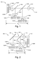
- Fig. 2 illustrates another illumination system 150, which is similar to system 100, like designated elements being the same.
- System 150 uses a mirror 152 that reflects the red light emitted by LED 102R toward the condenser lens 110.
- System 150 also uses a folding filter 154, which includes a first portion 156 that transmits green light emitted by LED 102G and reflects blue light emitted by LED 102B and a second portion 158 that transmits red light and reflects green and blue light.
- system 150 includes the other disadvantageous of system 100, such as the need for separate heatsinks and the need to independently mount and align the LEDs 102, which is cumbersome, time consuming and prone to error.
- Fig. 3 illustrates an illumination system 200 that includes multiple LEDs 202 that may be different colored, e.g., red, green and blue (individually referred to as LEDs 202R, 202G, and 202B).
- the LEDs 202 are aligned along the same axis (e.g., the X axis 201) so that the LEDs 202 emit light in the same general direction. In other words, the surface normal for the LEDs 202 are approximately parallel.
- the LEDs 202 may be any high powered LEDs.
- the LEDs 202 may be mounted along the same plane, which advantageously permits mounting of each LED 202 on the same heatsink 203.
- the light produced by LEDs 202R, 202G, and 202B is collimated by an associated collimator lens 204R, 204G, and 204B, respectively.
- the collimator lenses can be combined into a collimator system 204, which may be, e.g., injection molded acrylic.
- the use of LEDs 202 arranged in a single plane and on a single heatsink 203 and an integrated collimator system 204 advantageously reduces the number of piece parts, cost and simplifies the mounting of the LEDs 202. Accordingly, assembly of system 200 is straightforward and has a reduced risk of misalignment.
- the collimator system 204 modifies the radiation pattern of the LEDs to form narrower beams, which can then be reflected and/or filtered.
- the collimator system 204 may have any configuration include a single lens associated with each LED or a lens system associated with each LED.
- the collimator system 204 may use refractive, reflective or a combination of refractive and reflective elements to modify the radiation pattern of the LEDs.
- System 200 includes mirrors 206 and 208 that direct light from LEDs 202R and 202B, respectively, to a filter system 210 that is, e.g., disposed between mirrors 206 and 208.
- the mirrors 206, 208, and filter system 210 are configured to combine and direct the light from the LEDs 202 to a condenser lens 216.
- the filter system 210 may include two filters 212 and 214.
- the first filter 212 is a dichroic filter that reflects red light emitted by LED 202R and transmits green and blue light emitted by LEDs 202G and 202B, respectively.
- the second filter 214 is another dichroic filter that reflects blue light emitted by LED 202B and transmits red and green light emitted by LEDs 202R and 202G, respectively.
- One of either the first dichroic filter 212 or second dichroic filter 214 is split with the ends of the two split portions separated by and abutting the face and back of the other filter.
- filter system 210 may have other configurations.
- filter system 210 may be one or more dichroic prism, such as an X-cube may be used if desired.
- the light emitted by LEDs 202R and 202B are reflected by mirrors 206 and 208, respectively, and reflected by filter system 210 to the condenser lens 216, while the light emitted by LED 202G is transmitted directly through the filter system 210 to the condenser lens 216.
- the condenser lens 216 focuses the combined light onto a homogenizer or integrator rod 218, or other desired lens system, which may be located externally to system 200.
- system 200 Another advantage of system 200 is that the light paths from LEDs 202R and 202B are folded twice, i.e., first by mirrors 206 and 208, respectively, and second by filter system 210. Because the LED light path is folded twice, the length of the system 200 can be reduced with respect to system that only folds the light once, e.g., system 100 and 150. It should be understood that because the path from LED 102G to the condenser lens 216 is shorter than the path from either LED 102R and 102B to the condenser lens 216, the collimator lens 204G should be shaped differently than collimators 204R and 204G in order for the efficiencies to be the same. Thus, the use of a configuration of the mirrors and filters, such as shown in Fig. 3, along with the use of LEDs 202 arranged in a single plane and a single collimator system produces a compact illumination system.
- Fig. 4 illustrates a top plan view of system 200 installed in a frame 250 (the top portion of the frame is not shown).
- Frame 250 e.g., may be manufactured from machined metal or metal alloy, or from molded plastic or other similarly appropriate material.
- the mirrors 206, 208, and filter system 210 are mounted in the frame 250.
- the frame 250 may include slots or other guides in the bottom or along the sides that assist in positioning the components within frame 250.
- the top portion of the frame 250 (not shown) may include similar slots or guides to assist in properly positioning the components.
- the mirrors and filter system may be mounted in the frame 250 using, e.g., a glue or epoxy or by press fitting.
- the integrated collimator lens 204 is similarly mounted in the frame 250.
- the LEDs 202R, 202G, and 202B which are mounted on a single heatsink 203, can be easily and accurately mounted and properly aligned with collimator system 204, mirrors 206, 208, and filter system 210 by pressing the heatsink 203 against the frame 250 and affixing the heatsink 203 thereto, e.g., using screws, epoxy, retainer tabs or any other appropriate attaching means.
- the installation and alignment of the system 200 is simplified with respect to systems 100 and 150.
- Fig. 5 illustrates an illumination system 300 that is similar to system 200, like designated elements being the same.
- the LEDs 202R, 202G, and 202B are aligned along the same axis but are not mounted within the same plane.
- the LEDs 202 are mounted on a single heatsink 303.
- the heatsink 303 is not planar. Because the LEDs 202 are aligned in the same direction, i.e., the surface normal of LEDs 202 is approximately parallel, the configuration of mirror 206, 208, and filter system 210 may be the same as shown in system 200.
- System 300 includes separate collimator lenses 304R, 304G, and 304B due to the offset position of LED 202G.
- the offset position of LED 202G advantageously, increases the path length of the light from LED 202G to the condenser lens 216.
- the collimator lenses 304R, 304G, and 304B may have the same shape.
- Fig. 6 illustrates another illumination system 400 that includes a plurality of different colored LEDs 402 that, similar to system 200, are mounted along the same plane.
- System 400 by way of example includes LEDs that produce red, amber, green, cyan, and blue, individually referred to as LEDs 402R, 402A, 402G, 402C, and 402B.
- the LEDs 402 may all be mounted on a single heatsink 403.
- more than one heatsink may be used, e.g., LEDs 402R and 402A may be mounted on one heatsink, while LEDs 402G, 402C, and 402B may be mounted on a different heatsink.
- some LEDs 402 may be the same color, e.g., two LEDs may emit red light, two LEDs may emit green light, and one LED may emit blue light.
- system 400 may include a combined collimator system 404, with one or more collimator lenses associated with each LED 402.
- the collimator system 404 may use refractive elements, reflective elements or a combination thereof.
- the system 400 further includes a double folded light path for the LEDs 402, except for the center LED 402G.
- system includes mirrors 406 and 408, which reflect light from LEDs 402R and 402B, respectively.
- Filters 410 and 412 reflect amber light and cyan light emitted from LEDs 402A and 402C, respectively, and transmit the red and blue light from LEDs 402R and 402B, respectively.
- the filter system 414 includes a filter 416 that is transparent to the light emitted by LEDs 402G, 402C and 402B and reflects the light emitted by LEDs 402R and 402A.
- Filter system 414 also includes a split filter 418 that is transparent to the light emitted by LEDs 402G, 402R and 402A and reflects the light emitted by LEDs 402C and 402B.
- the light from LEDs 402 is combined and incident on condenser lens 420, which focuses the combined light onto a homogenizer or integrator rod 422, or other desired lens system, which may be located externally to system 400.
Abstract
Description
- The present invention relates to an illumination architecture that uses multiple light emitting diodes, and in particular to combining the light from multiple colored light emitting diodes.
- Display illumination devices, such as micro display projectors, use separate components of light, e.g., red, green, and blue components, and combine the separate components at the display. For example, in some display systems, light from a white high intensity discharge lamp is split into red, green, and blue channels using, e.g., dichroic mirrors, and the separate channels are sent to the corresponding display by the use of a mirror system. Alternatively, a color wheel is used to obtain the desired red, green, and blue components, from the white light, and the display is synchronized with the illuminator color. Starting from white light, however, is disadvantageous as such systems are typically bulky and inefficient.
- Some display systems use high powered light emitting diodes (LEDs) that emit red, green and blue light. Generally, however, display illumination devices that combine the colored light emitted from separate light emitting diodes are bulky and require many piece parts. Thus, assembly is time consuming and prone to alignment error.
- Accordingly, what is needed is an improved illumination device, e.g., that can be formed with a small footprint with a minimal number of piece parts.
- In accordance with an embodiment of the present invention, a compact illumination system that is suitable for, e.g., projection systems, includes a plurality of light emitting diodes that are aligned along the same axis. The illumination system includes mirrors and a filter system that is disposed between the mirrors. The combination of mirrors and filter system combine the light emitted by the different light emitting diodes while retaining a small footprint. The light emitting diodes may be mounted within the same plane, e.g., on the same heatsink, which simplifies assembly and alignment of the system.
Moreover, a collimator system with integrally formed collimators may be used, which reduces the number of piece parts and also simplifies assembly. - In one aspect of the present invention, an apparatus includes a first light emitting diode, a second light emitting diode and a third light emitting diode, each of which is aligned in the same approximate direction. The apparatus includes a first reflecting surface positioned to reflect light emitted from the first light emitting diode and a second reflecting surface positioned to reflect light emitted from the second light emitting diode. The apparatus includes a first filter disposed between the first reflecting surface and the second reflecting surface. The first filter is configured to reflect the light reflected from the first reflecting surface and to transmit light reflected from the second reflecting surface and the light emitted by the third light emitting diode. The apparatus also includes a second filter disposed between the first reflecting surface and the second reflecting surface and configured to reflect the light reflected from the second reflecting surface and to transmit light reflected from the first reflecting surface and the light emitted by the third light emitting diode. The first filter and second filter combine the light reflected from the first reflecting surface, the light reflected from the second reflecting surface and the light emitted from the third light emitting diode.
- In another aspect of the present invention, an apparatus includes a plurality of light emitting diodes positioned along the same plane, each light emitting diode emitting light aligned in the same direction. The apparatus includes a first reflecting surface positioned to reflect light emitted from a first light emitting diode and a second reflecting surface positioned to reflect light emitted from a second light emitting diode. A first filter is configured to reflect the light emitted from the first light emitting diode after being reflected from the first reflecting surface and being configured to transmit light that is emitted from the third light emitting diode. A second filter is configured to reflect the light emitted from the second light emitting diode after being reflected from the second reflecting surface and being configured to transmit light that is emitted from the third light emitting diode. The first filter and second filter combine the light emitted by the first light emitting diode, second light emitting diode and third light emitting diode.
- In another aspect of the present invention, a method includes providing a frame and mounting a collimator system to the frame, the collimator system including at least three collimators. The method further includes mounting a first mirror and a second mirror to the frame, the first mirror positioned to reflect light condensed by a first collimator and the second mirror positioned to reflect light condensed by a second collimator. A filter system is also mounted to the frame. The filter system is positioned to combine the light condensed by a third collimator with the light reflected by the first mirror and the light reflected by the second mirror. Additionally, a heatsink having at least three light emitting diodes is mounted to the frame such that each of the light emitting diodes is aligned with an associated collimator lens.
-
- Fig. 1 illustrates one possible illumination system that combines the light from multiple colored LEDs.
- Fig. 2 illustrates another illumination system.
- Fig. 3 illustrates an illumination system that includes multiple LEDs that are aligned in the same direction and mounted within the same plane.
- Fig. 4 illustrates a top plan view of the illumination system shown in Fig. 3 installed in a frame.
- Fig. 5 illustrates an illumination system that includes multiple LEDs that are aligned in the same direction, but not mounted within the same plane.
- Fig. 6 illustrates an illumination system similar to that shown in Fig. 3 but with additional LEDs.
-
- An illumination system, in accordance with an embodiment of the present invention, uses a number of separate LEDs that are aligned along the same axis and includes a compact lens and filter system that combines the light from the LEDs in a small footprint. Moreover, the LEDs may be mounted on the same heatsink. Accordingly, the assembly and alignment of the illumination system is straightforward, which reduces costs and error.
- Fig. 1 illustrates one
possible illumination system 100 that combines the light from multiple colored LEDs with acondenser lens 110. Thecondenser lens 110 focuses the combined light onto a homogenizer orintegrator rod 112, which may be located externally tosystem 100.System 100 includes ared LED 102R, agreen LED 102G and a blue LEG 102B (collectively referred to herein as LEDs 102). The light emitted from eachLED collimator lens - The
system 100 includesdichroic filters Filter 106 is transparent to red light and reflects green light, whilefilter 108 is transparent to both red and green light, but reflects blue light. Thus, prior to being received by acondenser lens 110, red light emitted byLED 102R is passed through bothfilters LED 102G is reflected byfilter 106 and passed throughfilter 108, and blue light emitted byLED 102B is reflected byfilter 108. Of course, if the order of LEDs is arranged differently, other combinations of filters may be used. - Because the LEDs 102 generate heat, and the efficiency of an LED is reduced with elevated temperatures,
heatsinks LEDs - In a system where the LEDs 102 have the same chip sizes and the collimators 104 are the same for all the LEDs, the distance between the collimators 104 and the
condenser lens 110 needs to by the same for all LEDs 102. Thus, the total size of thesystem 100, as represented by dimension X100 in Fig. 1, is large, makingsystem 100 unsuitable for small applications. - Additionally, as can be seen in Fig. 1, the LEDs 102 are mounted in three different planes and
LED 102R is aligned with an orthogonal orientation relative toLEDs system 100. Thus, thesystem 100 includes a number of piece parts that must be accurately assembled and aligned in order for thesystem 100 to operate properly. Accordingly, the assembly ofsystem 100 is cumbersome, time consuming, and prone to error. - Fig. 2 illustrates another
illumination system 150, which is similar tosystem 100, like designated elements being the same.System 150, however, uses amirror 152 that reflects the red light emitted byLED 102R toward thecondenser lens 110.System 150 also uses afolding filter 154, which includes afirst portion 156 that transmits green light emitted byLED 102G and reflects blue light emitted byLED 102B and asecond portion 158 that transmits red light and reflects green and blue light. - The configuration illustrated in Fig. 2 is advantageous as the size, illustrated by dimension X150, is reduced relative to the
system 100 shown in Fig. 1. Nevertheless,system 150 includes the other disadvantageous ofsystem 100, such as the need for separate heatsinks and the need to independently mount and align the LEDs 102, which is cumbersome, time consuming and prone to error. - Fig. 3 illustrates an
illumination system 200 that includes multiple LEDs 202 that may be different colored, e.g., red, green and blue (individually referred to asLEDs - As illustrated in Fig. 3, the LEDs 202 may be mounted along the same plane, which advantageously permits mounting of each LED 202 on the
same heatsink 203. The light produced byLEDs collimator lens collimator system 204, which may be, e.g., injection molded acrylic. The use of LEDs 202 arranged in a single plane and on asingle heatsink 203 and anintegrated collimator system 204 advantageously reduces the number of piece parts, cost and simplifies the mounting of the LEDs 202. Accordingly, assembly ofsystem 200 is straightforward and has a reduced risk of misalignment. - The
collimator system 204 modifies the radiation pattern of the LEDs to form narrower beams, which can then be reflected and/or filtered. Thecollimator system 204 may have any configuration include a single lens associated with each LED or a lens system associated with each LED. Moreover, thecollimator system 204 may use refractive, reflective or a combination of refractive and reflective elements to modify the radiation pattern of the LEDs. -
System 200 includesmirrors LEDs filter system 210 that is, e.g., disposed betweenmirrors mirrors filter system 210 are configured to combine and direct the light from the LEDs 202 to acondenser lens 216. Thefilter system 210 may include twofilters first filter 212 is a dichroic filter that reflects red light emitted byLED 202R and transmits green and blue light emitted byLEDs second filter 214 is another dichroic filter that reflects blue light emitted byLED 202B and transmits red and green light emitted byLEDs dichroic filter 212 or seconddichroic filter 214 is split with the ends of the two split portions separated by and abutting the face and back of the other filter. It should be understood thatfilter system 210 may have other configurations. By way of example,filter system 210 may be one or more dichroic prism, such as an X-cube may be used if desired. - Thus, the light emitted by
LEDs mirrors filter system 210 to thecondenser lens 216, while the light emitted byLED 202G is transmitted directly through thefilter system 210 to thecondenser lens 216. Thecondenser lens 216 focuses the combined light onto a homogenizer orintegrator rod 218, or other desired lens system, which may be located externally tosystem 200. - Of course, if the order of the LEDs 202 is arranged differently, other combinations of filters may be used.
- Another advantage of
system 200 is that the light paths fromLEDs mirrors filter system 210. Because the LED light path is folded twice, the length of thesystem 200 can be reduced with respect to system that only folds the light once, e.g.,system LED 102G to thecondenser lens 216 is shorter than the path from eitherLED condenser lens 216, thecollimator lens 204G should be shaped differently thancollimators - Fig. 4 illustrates a top plan view of
system 200 installed in a frame 250 (the top portion of the frame is not shown).Frame 250, e.g., may be manufactured from machined metal or metal alloy, or from molded plastic or other similarly appropriate material. As illustrated in Fig. 4, themirrors filter system 210 are mounted in theframe 250. In one embodiment, theframe 250 may include slots or other guides in the bottom or along the sides that assist in positioning the components withinframe 250. The top portion of the frame 250 (not shown) may include similar slots or guides to assist in properly positioning the components. The mirrors and filter system may be mounted in theframe 250 using, e.g., a glue or epoxy or by press fitting. Theintegrated collimator lens 204 is similarly mounted in theframe 250. - As illustrated by
arrow 252 in Fig. 4, theLEDs single heatsink 203, can be easily and accurately mounted and properly aligned withcollimator system 204, mirrors 206, 208, andfilter system 210 by pressing theheatsink 203 against theframe 250 and affixing theheatsink 203 thereto, e.g., using screws, epoxy, retainer tabs or any other appropriate attaching means. Thus, as can be seen in Fig. 4, the installation and alignment of thesystem 200 is simplified with respect tosystems - Fig. 5 illustrates an
illumination system 300 that is similar tosystem 200, like designated elements being the same. As illustrated in Fig. 5, theLEDs single heatsink 303. Theheatsink 303, however, is not planar. Because the LEDs 202 are aligned in the same direction, i.e., the surface normal of LEDs 202 is approximately parallel, the configuration ofmirror filter system 210 may be the same as shown insystem 200.System 300 includesseparate collimator lenses LED 202G. The offset position ofLED 202G, advantageously, increases the path length of the light fromLED 202G to thecondenser lens 216. Thus, in an embodiment in which the path length for light emitted fromLED 202G is the same as the path length for light emitted fromLEDs collimator lenses - Fig. 6 illustrates another
illumination system 400 that includes a plurality of different colored LEDs 402 that, similar tosystem 200, are mounted along the same plane.System 400 by way of example includes LEDs that produce red, amber, green, cyan, and blue, individually referred to asLEDs single heatsink 403. Of course, if desired, more than one heatsink may be used, e.g.,LEDs LEDs - As with
system 200,system 400 may include a combinedcollimator system 404, with one or more collimator lenses associated with each LED 402. Thecollimator system 404 may use refractive elements, reflective elements or a combination thereof. Thesystem 400 further includes a double folded light path for the LEDs 402, except for thecenter LED 402G. Thus, system includesmirrors LEDs Filters LEDs LEDs filter system 414 includes afilter 416 that is transparent to the light emitted byLEDs LEDs Filter system 414 also includes asplit filter 418 that is transparent to the light emitted byLEDs LEDs condenser lens 420, which focuses the combined light onto a homogenizer orintegrator rod 422, or other desired lens system, which may be located externally tosystem 400. - Although the present invention is illustrated in connection with specific embodiments for instructional purposes, the present invention is not limited thereto. Various adaptations and modifications may be made without departing from the scope of the invention. For example, the description of the colors the order of the LEDs is exemplary and other colors, orders or duplicative colors may be used. Moreover, different types of LEDs may be used with the present invention. Therefore, the spirit and scope of the appended claims should not be limited to the foregoing description.
Claims (29)
- An apparatus comprising:wherein the first filter and second filter combine the light reflected from the first reflecting surface, the light reflected from the second reflecting surface and the light emitted from the third light emitting diode.a first light emitting diode, a second light emitting diode and a third light emitting diode, each of which is aligned in the same approximate direction;a first reflecting surface positioned to reflect light emitted from the first light emitting diode;a second reflecting surface positioned to reflect light emitted from the second light emitting diode;a first filter disposed between the first reflecting surface and the second reflecting surface and configured to reflect the light reflected from the first reflecting surface and to transmit light reflected from the second reflecting surface and the light emitted by the third light emitting diode; anda second filter disposed between the first reflecting surface and the second reflecting surface and configured to reflect the light reflected from the second reflecting surface and to transmit light reflected from the first reflecting surface and the light emitted by the third light emitting diode;
- The apparatus of Claim 1, the apparatus further comprising a collimator system, the collimator system comprising:a first collimator associated with the first light emitting diode, the first collimator collimating the light emitted by the first light emitting diode prior to reflecting from the first reflecting surface;a second collimator associated with the second light emitting diode, the second collimator collimating the light emitted by the second light emitting diode prior to reflecting from the second reflecting surface; anda third collimator associated with the third light emitting diode, the third collimator collimating the light emitted by the third light emitting diode prior to being transmitted through the first filter and the second filter.
- The apparatus of Claim 2, the apparatus further comprising:a frame holding the first reflecting surface, the second reflecting surface, the first filter and the second filter, and the collimator system;a heatsink, the first light emitting diode, second light emitting diode, and third light emitting diode are mounted on the heatsink, the heatsink mounted to the frame.
- The apparatus of Claim 1, wherein the first filter and second filter are dichroic filters positioned orthogonally relative to one another.
- The apparatus of Claim 4, wherein first filter has a front surface and a back surface, and wherein the second filter comprises two halves, a first half having an end that abuts the front surface of the first filter and the second half having an end that abuts the back surface of the first filter.
- The apparatus of Claim 1, wherein the first filter and second filter are formed from an X-cube prism.
- The apparatus of Claim 1, the apparatus further comprising a lens configured to receive the combined light from the first filter and the second filter.
- The apparatus of Claim 1, wherein the first light emitting diode, second light emitting diode and third light emitting diode each emit light of a different color, the colors being red, green and blue.
- The apparatus of Claim 1, wherein the first light emitting diode, second light emitting diode and third light emitting diode lie within the same plane.
- The apparatus of Claim 1, the apparatus further comprising a heatsink, wherein the first light emitting diode, second light emitting diode, and third light emitting diode are mounted on the heatsink.
- The apparatus of Claim 1, the apparatus further comprising:wherein the first filter is further configured to reflect the light reflected from the third reflecting surface and to transmit light reflected from the fourth reflecting surface, and the second filter is further configured to reflect the light reflected from the fourth reflecting surface and to transmit light reflected from the third reflecting surface, and wherein the first filter and second filter combine the light reflected from the first reflecting surface, the light reflected from the second reflecting surface, the light reflected from the third reflecting surface, the light from the fourth reflecting surface and the light emitted from the third light emitting diode.a fourth light emitting diode and a fifth light emitting diode that are aligned in the same approximate direction as the first light emitting diode, second light emitting diode, and third light emitting diode;a third reflecting surface positioned to reflect light emitted from the fourth light emitting diode;a fourth reflecting surface positioned to reflect light emitted from the fifth light emitting diode;
- The apparatus of Claim 11, wherein the third reflecting surface is configured to transmit light reflected from the first reflecting surface and the fourth reflecting surface is configured to transmit light reflected from the second reflecting surface.
- The apparatus of Claim 11, wherein the first light emitting diode, second light emitting diode, third light emitting diode, fourth light emitting diode, and fifth light emitting diode each emit light of a different color, the colors being red, amber, green, cyan, and blue.
- An apparatus comprising:a plurality of light emitting diodes positioned along the same plane, each light emitting diode emitting light aligned in the same direction;a first reflecting surface positioned to reflect light emitted from a first light emitting diode;a second reflecting surface positioned to reflect light emitted from a second light emitting diode;a first filter configured to reflect the light emitted from the first light emitting diode after being reflected from the first reflecting surface and being configured to transmit light that is emitted from the third light emitting diode; anda second filter configured to reflect the light emitted from the second light emitting diode after being reflected from the second reflecting surface and being configured to transmit light that is emitted from the third light emitting diode; wherein the first filter and second filter combine the light emitted by the first light emitting diode, second light emitting diode and third light emitting diode.
- The apparatus of Claim 14, further comprising a lens configured to receive the combined light from the first filter and the second filter.
- The apparatus of Claim 15, the apparatus further comprising:a frame holding the first reflecting surface, the second reflecting surface, the first filter and the second filter, and the lens;a heatsink, the first light emitting diode, second light emitting diode, and third light emitting diode being mounted on the heatsink, the heatsink mounted to the frame.
- The apparatus of Claim 16, the apparatus further comprising:wherein the frame further holds the collimator lens system.a collimator system comprising:a first collimator associated with the first light emitting diode;a second collimator associated with the second light emitting diode; anda third collimator associated with the third light emitting diode;
- The apparatus of Claim 14, wherein the first filter and the second filter are disposed between the first reflecting surface and the second reflecting surface.
- The apparatus of Claim 14, wherein the first filter and second filter are dichroic filters positioned orthogonally relative to one another.
- The apparatus of Claim 19, wherein first filter has a front surface and a back surface, and wherein the second filter comprises two halves, a first half having an end that abuts the front surface of the first filter and the second half having an end that abuts the back surface of the first filter.
- The apparatus of Claim 14, wherein the first filter and second filter are formed from an X-cube prism.
- The apparatus of Claim 14, wherein the first light emitting diode, second light emitting diode and third light emitting diode each emit light of a different color, the colors being red, green and blue.
- A method comprising:providing a frame;mounting a collimator system to the frame, the collimator system including at least three collimators;mounting a first mirror and a second mirror to the frame, the first mirror positioned to reflect light condensed by a first collimator and the second mirror positioned to reflect light condensed by a second collimator;mounting a filter system to the frame, the filter system positioned to combine the light condensed by a third collimator with the light reflected by the first mirror and the light reflected by the second mirror; andmounting a heatsink having at least three light emitting diodes to the frame, wherein mounting the heatsink aligns each of the light emitting diodes with an associated collimator in the collimator system.
- The method of Claim 23, further comprising mounting the at least three light emitting diodes on the heatsink.
- The method of Claim 23, wherein mounting a filter system to the frame comprises:mounting a first dichroic filter to the frame; andmounting second dichroic filter to the frame, the second dichroic filter having a first portion mounted on a first side of the first dichroic filter and a second portion mounted on a second side of the first dichroic filter such that the first dichroic filter and the second dichroic filter are oriented orthogonally to each other.
- The method of Claim 23, wherein mounting a filter system to the frame comprises mounting an X-cube prism to the frame.
- The method of Claim 23, further comprising mounting a condenser lens to the frame, the condenser lens positioned to receive the light combined by the filter system.
- The method of Claim 23, wherein the at least three collimators are lenses integrally formed within the collimator system.
- The method of Claim 23, wherein a plurality of the light emitting diodes emit different colored light, the colors being red, green and blue.
Applications Claiming Priority (2)
| Application Number | Priority Date | Filing Date | Title |
|---|---|---|---|
| US10/789,834 US7212344B2 (en) | 2004-02-27 | 2004-02-27 | Illumination system with aligned LEDs |
| US789834 | 2004-02-27 |
Publications (2)
| Publication Number | Publication Date |
|---|---|
| EP1569467A2 true EP1569467A2 (en) | 2005-08-31 |
| EP1569467A3 EP1569467A3 (en) | 2006-05-24 |
Family
ID=34750563
Family Applications (1)
| Application Number | Title | Priority Date | Filing Date |
|---|---|---|---|
| EP05101321A Withdrawn EP1569467A3 (en) | 2004-02-27 | 2005-02-22 | Illumination system with aligned leds |
Country Status (4)
| Country | Link |
|---|---|
| US (1) | US7212344B2 (en) |
| EP (1) | EP1569467A3 (en) |
| JP (1) | JP2005242364A (en) |
| TW (1) | TW200541109A (en) |
Cited By (8)
| Publication number | Priority date | Publication date | Assignee | Title |
|---|---|---|---|---|
| WO2007056541A2 (en) * | 2005-11-08 | 2007-05-18 | Young Garrett J | Apparatus and method for generating light from multi - primary colors |
| WO2007060592A3 (en) * | 2005-11-22 | 2007-10-18 | Koninkl Philips Electronics Nv | Light emitting module and manufacturing method |
| WO2008073105A1 (en) * | 2006-12-15 | 2008-06-19 | Thomson Licensing | Illumination module and method |
| US7866849B2 (en) | 2006-07-31 | 2011-01-11 | Koninklijke Philips Electronics N.V. | Light-emitting device |
| GB2484712A (en) * | 2010-10-21 | 2012-04-25 | Optovate Ltd | Illumination Apparatus |
| GB2484711A (en) * | 2010-10-21 | 2012-04-25 | Optovate Ltd | Illumination Apparatus |
| CN108445699A (en) * | 2015-05-12 | 2018-08-24 | 苏州佳世达光电有限公司 | Projection arrangement |
| US10824060B2 (en) | 2016-08-19 | 2020-11-03 | Sony Corporation | Light source module, method of manufacturing light source module, and projection-type display unit |
Families Citing this family (66)
| Publication number | Priority date | Publication date | Assignee | Title |
|---|---|---|---|---|
| JP3909595B2 (en) * | 2003-04-23 | 2007-04-25 | セイコーエプソン株式会社 | Display device and dimming method thereof |
| DE10345431B4 (en) * | 2003-09-30 | 2009-10-22 | Carl Zeiss Jena Gmbh | Device for the homogeneous multicolor illumination of a surface |
| US7524084B2 (en) * | 2004-03-30 | 2009-04-28 | Sanyo Electric Co., Ltd. | Illuminating device, and projection type video display |
| DE202005006418U1 (en) * | 2004-04-23 | 2005-09-08 | Infocus Corp., Wilsonville | Arrangement of light-emitting devices in projection systems |
| JP4123189B2 (en) * | 2004-05-19 | 2008-07-23 | ソニー株式会社 | Backlight device and liquid crystal display device |
| US7232224B2 (en) * | 2004-08-26 | 2007-06-19 | Texas Instruments Incorporated | Simultaneous color illumination |
| KR100644632B1 (en) * | 2004-10-01 | 2006-11-10 | 삼성전자주식회사 | Illumination unit adopting LED and projection display using the same |
| WO2006059272A1 (en) * | 2004-11-30 | 2006-06-08 | Koninklijke Philips Electronics N.V. | Miniaturized projection display |
| TWI281089B (en) * | 2004-12-09 | 2007-05-11 | Coretronic Corp | Illumination system |
| EP1842380B1 (en) | 2005-01-24 | 2013-10-23 | Thomson Licensing | Video error detection technique using a crc parity code |
| US9201295B2 (en) * | 2005-01-25 | 2015-12-01 | Jabil Circuit, Inc. | High efficiency LED optical engine for a digital light processing (DLP) projector and method of forming same |
| TWI284778B (en) * | 2005-03-07 | 2007-08-01 | Coretronic Corp | Light source device for projector |
| KR100683171B1 (en) * | 2005-03-08 | 2007-02-15 | 삼성전자주식회사 | Cooling apparatus and projector having the same |
| KR20060111793A (en) * | 2005-04-25 | 2006-10-30 | 삼성전자주식회사 | Illuminating unit and image projection apparatus employing the same |
| KR20060125346A (en) * | 2005-06-02 | 2006-12-06 | 삼성전자주식회사 | Illumination system controlled aspect ratio and projection system employing the illumination system |
| DE102005044580A1 (en) * | 2005-09-17 | 2007-04-05 | Carl Zeiss Jena Gmbh | Arrangement for illuminating a field |
| KR20070040243A (en) * | 2005-10-11 | 2007-04-16 | 삼성전자주식회사 | Light generating unit and display device having the same |
| WO2007069119A1 (en) * | 2005-12-14 | 2007-06-21 | Philips Intellectual Property & Standards Gmbh | Lighting device and method for manufacturing same |
| TWI308966B (en) * | 2006-04-17 | 2009-04-21 | Young Optics Inc | Illumination system and projection apparatus |
| CN101063798B (en) * | 2006-04-27 | 2010-06-16 | 三洋电机株式会社 | Projection-type image display device |
| US20070291505A1 (en) * | 2006-06-02 | 2007-12-20 | Rance Fortenberry | Light source assembly with integrated optical pipe |
| KR100771636B1 (en) * | 2006-07-04 | 2007-10-31 | 엘지전자 주식회사 | Projection system |
| US20080025040A1 (en) * | 2006-07-25 | 2008-01-31 | Swantner Michael J | LED light engine |
| JP4966701B2 (en) * | 2006-08-03 | 2012-07-04 | ハリソン東芝ライティング株式会社 | Hollow surface lighting device |
| US9243794B2 (en) | 2006-09-30 | 2016-01-26 | Cree, Inc. | LED light fixture with fluid flow to and from the heat sink |
| US9028087B2 (en) | 2006-09-30 | 2015-05-12 | Cree, Inc. | LED light fixture |
| US7686469B2 (en) | 2006-09-30 | 2010-03-30 | Ruud Lighting, Inc. | LED lighting fixture |
| US20090086491A1 (en) | 2007-09-28 | 2009-04-02 | Ruud Lighting, Inc. | Aerodynamic LED Floodlight Fixture |
| US7952262B2 (en) | 2006-09-30 | 2011-05-31 | Ruud Lighting, Inc. | Modular LED unit incorporating interconnected heat sinks configured to mount and hold adjacent LED modules |
| CN101529308A (en) * | 2006-10-20 | 2009-09-09 | 皇家飞利浦电子股份有限公司 | Light emitting device with collimating structure |
| US7766490B2 (en) * | 2006-12-13 | 2010-08-03 | Philips Lumileds Lighting Company, Llc | Multi-color primary light generation in a projection system using LEDs |
| US20080144183A1 (en) * | 2006-12-18 | 2008-06-19 | Motorola, Inc. | Compact three color laser system with light intensity sensor |
| US7740391B2 (en) * | 2007-02-21 | 2010-06-22 | Wintek Corporation | Backlight module |
| US7682027B2 (en) * | 2007-04-09 | 2010-03-23 | Alcon, Inc. | Multi-LED ophthalmic illuminator |
| KR101330906B1 (en) * | 2007-04-30 | 2013-11-18 | 엘지전자 주식회사 | Projection Optical System |
| TWI388880B (en) * | 2007-06-20 | 2013-03-11 | Delta Electronics Inc | Light source module and display system comprising the light source module |
| CN101334142B (en) * | 2007-06-26 | 2010-06-16 | 台达电子工业股份有限公司 | Digital light processing displaying system |
| TWI375108B (en) | 2007-12-14 | 2012-10-21 | Young Optics Inc | Light projection apparatus and light-mixing module thereof |
| JP5108490B2 (en) * | 2007-12-19 | 2012-12-26 | オリンパス株式会社 | Lighting device for cell analyzer |
| JP2009237546A (en) * | 2008-03-07 | 2009-10-15 | Sanyo Electric Co Ltd | Projection type image display device, and illumination device |
| TWI358601B (en) * | 2008-03-14 | 2012-02-21 | Young Optics Inc | Light-mixing device and projector |
| US7703946B2 (en) * | 2008-05-23 | 2010-04-27 | Display Products, Inc. | LED wall wash light |
| TWI376562B (en) * | 2008-06-04 | 2012-11-11 | Delta Electronics Inc | Light transformation apparatus and light source apparatus comprising the same |
| JP2010032744A (en) * | 2008-07-29 | 2010-02-12 | Ricoh Co Ltd | Illuminating device |
| US20100246171A1 (en) * | 2009-03-26 | 2010-09-30 | Scale Timothy J | LED Replacement Projector Light Source |
| TWM373496U (en) * | 2009-07-29 | 2010-02-01 | Chunghwa Picture Tubes Ltd | Collimated system with multi-backlight source |
| CN101620366B (en) * | 2009-08-17 | 2011-09-07 | 方恒 | Projecting apparatus using high-power LED array as light source |
| JP5436097B2 (en) * | 2009-08-25 | 2014-03-05 | 三菱電機株式会社 | Condensing optical system and projection-type image display device |
| CA2779965A1 (en) * | 2009-12-17 | 2011-06-23 | Alcon Research, Ltd. | Photonic lattice leds for ophthalmic illumination |
| US20110148304A1 (en) * | 2009-12-22 | 2011-06-23 | Artsyukhovich Alexander N | Thermoelectric cooling for increased brightness in a white light l.e.d. illuminator |
| WO2011078958A1 (en) * | 2009-12-23 | 2011-06-30 | Alcon Research, Ltd. | Enhanced led illuminator |
| TW201128225A (en) * | 2010-02-12 | 2011-08-16 | Young Optics Inc | Light-mixing device |
| US9314374B2 (en) * | 2010-03-19 | 2016-04-19 | Alcon Research, Ltd. | Stroboscopic ophthalmic illuminator |
| US20110285969A1 (en) * | 2010-05-18 | 2011-11-24 | Liu-Liang Liao | Micro projection device for simplifying optical component and increasing light-guiding precision |
| US8141388B2 (en) * | 2010-05-26 | 2012-03-27 | Corning Incorporated | Radiation collimator for infrared heating and/or cooling of a moving glass sheet |
| JP5648372B2 (en) | 2010-08-25 | 2015-01-07 | ウシオ電機株式会社 | Light source device |
| US8573801B2 (en) | 2010-08-30 | 2013-11-05 | Alcon Research, Ltd. | LED illuminator |
| JP2012155155A (en) * | 2011-01-26 | 2012-08-16 | Sanyo Electric Co Ltd | Optical element and projection type video display apparatus |
| DE102012008641A1 (en) * | 2012-05-02 | 2013-11-07 | Heraeus Noblelight Gmbh | Lamp with reflector |
| US10788678B2 (en) | 2013-05-17 | 2020-09-29 | Excelitas Canada, Inc. | High brightness solid state illumination system for fluorescence imaging and analysis |
| EP3164757A1 (en) | 2014-07-01 | 2017-05-10 | Philips Lighting Holding B.V. | A lighting device providing light mixed from several light sources |
| TWI591419B (en) * | 2015-05-05 | 2017-07-11 | 佳世達科技股份有限公司 | Projector and electronic device |
| US10520824B2 (en) | 2016-03-03 | 2019-12-31 | Asml Netherlands B.V. | Wavelength combining of multiple source |
| US11172560B2 (en) | 2016-08-25 | 2021-11-09 | Alcon Inc. | Ophthalmic illumination system with controlled chromaticity |
| KR102256984B1 (en) * | 2018-12-31 | 2021-05-27 | 한국광기술원 | Underwater Optical Apparatus and Underwater Lighting Apparatus Including the Same |
| DE102020126260A1 (en) * | 2019-10-17 | 2021-04-22 | Phoseon Technology, Inc. | Methods and systems for a multi-wavelength lighting system |
Citations (2)
| Publication number | Priority date | Publication date | Assignee | Title |
|---|---|---|---|---|
| US20030156416A1 (en) * | 2002-02-21 | 2003-08-21 | Whelen Engineering Company, Inc. | Led light assembly |
| EP1365598A2 (en) * | 2002-05-20 | 2003-11-26 | Eastman Kodak Company | Method and apparatus for increasing color gamut of a display |
Family Cites Families (19)
| Publication number | Priority date | Publication date | Assignee | Title |
|---|---|---|---|---|
| JPH04263244A (en) * | 1991-02-16 | 1992-09-18 | Semiconductor Energy Lab Co Ltd | Image display device |
| EP0530378B1 (en) * | 1991-03-20 | 1999-01-07 | Mitsubishi Denki Kabushiki Kaisha | Projection type display device |
| JP2924654B2 (en) * | 1994-07-29 | 1999-07-26 | 日本ビクター株式会社 | Video projector |
| US6281949B1 (en) * | 1997-03-24 | 2001-08-28 | Sony Corporation | Apparatus for displaying a picture which involves spatially modulating a light beam |
| JP3941167B2 (en) * | 1997-03-24 | 2007-07-04 | ソニー株式会社 | Video display device and video display method |
| US5971545A (en) * | 1997-06-25 | 1999-10-26 | Hewlett-Packard Company | Light source for projection display |
| JPH1152889A (en) * | 1997-07-31 | 1999-02-26 | Ricoh Co Ltd | Image display device |
| JPH1164849A (en) * | 1997-08-26 | 1999-03-05 | Sanyo Electric Co Ltd | Light source for liquid crystal display device and color liquid crystal display device using it |
| WO1999049358A1 (en) * | 1998-03-26 | 1999-09-30 | Mitsubishi Denki Kabushiki Kaisha | Image display and light-emitting device |
| US6019474A (en) * | 1998-10-06 | 2000-02-01 | International Business Machines Corporation | Modified X-cube arrangement for improved contrast projection display |
| JP2000131507A (en) * | 1998-10-27 | 2000-05-12 | Matsushita Electric Ind Co Ltd | Lens array plate, light valve device, projection type display device, and viewfinder device |
| JP2000180959A (en) * | 1998-12-10 | 2000-06-30 | Samsung Sdi Co Ltd | Laser video projecting device using optical pumping bulb |
| EP1103759A3 (en) | 1999-11-11 | 2005-02-23 | Toyoda Gosei Co., Ltd. | Full-color light source unit |
| JP4769369B2 (en) * | 2000-05-29 | 2011-09-07 | キヤノン株式会社 | Projection device |
| KR100444986B1 (en) * | 2001-09-29 | 2004-08-21 | 삼성전자주식회사 | Illumination system and a projector imploying it |
| JP4111011B2 (en) * | 2002-03-14 | 2008-07-02 | ソニー株式会社 | Projection screen |
| JP2003337380A (en) * | 2002-05-21 | 2003-11-28 | Sharp Corp | Projection type display |
| US7289090B2 (en) * | 2003-12-10 | 2007-10-30 | Texas Instruments Incorporated | Pulsed LED scan-ring array for boosting display system lumens |
| US7090357B2 (en) * | 2003-12-23 | 2006-08-15 | 3M Innovative Properties Company | Combined light source for projection display |
-
2004
- 2004-02-27 US US10/789,834 patent/US7212344B2/en active Active
-
2005
- 2005-02-22 EP EP05101321A patent/EP1569467A3/en not_active Withdrawn
- 2005-02-24 TW TW094105514A patent/TW200541109A/en unknown
- 2005-02-28 JP JP2005053883A patent/JP2005242364A/en active Pending
Patent Citations (2)
| Publication number | Priority date | Publication date | Assignee | Title |
|---|---|---|---|---|
| US20030156416A1 (en) * | 2002-02-21 | 2003-08-21 | Whelen Engineering Company, Inc. | Led light assembly |
| EP1365598A2 (en) * | 2002-05-20 | 2003-11-26 | Eastman Kodak Company | Method and apparatus for increasing color gamut of a display |
Cited By (15)
| Publication number | Priority date | Publication date | Assignee | Title |
|---|---|---|---|---|
| US8624941B2 (en) | 2005-11-08 | 2014-01-07 | Prism Projection, Inc. | Apparatus, methods, and systems for multi-primary display or projection |
| WO2007056541A3 (en) * | 2005-11-08 | 2007-10-25 | Garrett J Young | Apparatus and method for generating light from multi - primary colors |
| WO2007056541A2 (en) * | 2005-11-08 | 2007-05-18 | Young Garrett J | Apparatus and method for generating light from multi - primary colors |
| US10008178B2 (en) | 2005-11-08 | 2018-06-26 | Prism Projection, Inc | Apparatus, methods, and systems for multi-primary display or projection |
| US7859554B2 (en) | 2005-11-08 | 2010-12-28 | Young Garrett J | Apparatus, methods, and systems for multi-primary display or projection |
| WO2007060592A3 (en) * | 2005-11-22 | 2007-10-18 | Koninkl Philips Electronics Nv | Light emitting module and manufacturing method |
| US7866849B2 (en) | 2006-07-31 | 2011-01-11 | Koninklijke Philips Electronics N.V. | Light-emitting device |
| WO2008073105A1 (en) * | 2006-12-15 | 2008-06-19 | Thomson Licensing | Illumination module and method |
| CN101563637B (en) * | 2006-12-15 | 2013-04-10 | 汤姆森特许公司 | Illumination module and method |
| CN101563637A (en) * | 2006-12-15 | 2009-10-21 | 汤姆森特许公司 | Illumination module and method |
| GB2484711A (en) * | 2010-10-21 | 2012-04-25 | Optovate Ltd | Illumination Apparatus |
| GB2484712A (en) * | 2010-10-21 | 2012-04-25 | Optovate Ltd | Illumination Apparatus |
| US9080752B2 (en) | 2010-10-21 | 2015-07-14 | Optovate Limited | Illumination apparatus |
| CN108445699A (en) * | 2015-05-12 | 2018-08-24 | 苏州佳世达光电有限公司 | Projection arrangement |
| US10824060B2 (en) | 2016-08-19 | 2020-11-03 | Sony Corporation | Light source module, method of manufacturing light source module, and projection-type display unit |
Also Published As
| Publication number | Publication date |
|---|---|
| TW200541109A (en) | 2005-12-16 |
| EP1569467A3 (en) | 2006-05-24 |
| US20050190562A1 (en) | 2005-09-01 |
| US7212344B2 (en) | 2007-05-01 |
| JP2005242364A (en) | 2005-09-08 |
Similar Documents
| Publication | Publication Date | Title |
|---|---|---|
| EP1569467A2 (en) | Illumination system with aligned leds | |
| US9814378B2 (en) | Full spectrum LED illuminator having a mechanical enclosure and heatsink | |
| JP5978997B2 (en) | Light source unit, lighting device and display device | |
| US10827153B2 (en) | Projection device | |
| JP4471903B2 (en) | Illumination unit and image projection apparatus employing the same | |
| CN108604050B (en) | Light source device and projector | |
| TWI570500B (en) | A light source device, a lighting device, and a projector | |
| JP5282290B2 (en) | Illumination optical system and image projection apparatus provided with illumination optical system | |
| US9116421B1 (en) | Projector with laser illumination elements offset along an offset axis | |
| CN108227358B (en) | Illumination device and projector | |
| US9016865B2 (en) | Illumination device and projection type display device using the same | |
| JP2017167415A (en) | Light source device and projector | |
| WO2011148499A1 (en) | Illuminating optical system and projection display device | |
| JP2008268601A (en) | Illumination optical system | |
| US10690931B2 (en) | Light source device and projection display apparatus | |
| JP4118244B2 (en) | Illumination device and projection display device | |
| CN113759647A (en) | Illumination device and projector | |
| US20230259012A1 (en) | Illumination device and projector | |
| WO2015166596A1 (en) | Array light source and illumination optical system using array light source |
Legal Events
| Date | Code | Title | Description |
|---|---|---|---|
| PUAI | Public reference made under article 153(3) epc to a published international application that has entered the european phase |
Free format text: ORIGINAL CODE: 0009012 |
|
| AK | Designated contracting states |
Kind code of ref document: A2 Designated state(s): AT BE BG CH CY CZ DE DK EE ES FI FR GB GR HU IE IS IT LI LT LU MC NL PL PT RO SE SI SK TR |
|
| AX | Request for extension of the european patent |
Extension state: AL BA HR LV MK YU |
|
| PUAL | Search report despatched |
Free format text: ORIGINAL CODE: 0009013 |
|
| AK | Designated contracting states |
Kind code of ref document: A3 Designated state(s): AT BE BG CH CY CZ DE DK EE ES FI FR GB GR HU IE IS IT LI LT LU MC NL PL PT RO SE SI SK TR |
|
| AX | Request for extension of the european patent |
Extension state: AL BA HR LV MK YU |
|
| 17P | Request for examination filed |
Effective date: 20061124 |
|
| AKX | Designation fees paid |
Designated state(s): DE |
|
| 17Q | First examination report despatched |
Effective date: 20070216 |
|
| RAP1 | Party data changed (applicant data changed or rights of an application transferred) |
Owner name: PHILIPS LUMILEDS LIGHTING COMPANY LLC |
|
| STAA | Information on the status of an ep patent application or granted ep patent |
Free format text: STATUS: THE APPLICATION IS DEEMED TO BE WITHDRAWN |
|
| 18D | Application deemed to be withdrawn |
Effective date: 20090901 |