EP1570778A1 - Endoscope system - Google Patents
Endoscope system Download PDFInfo
- Publication number
- EP1570778A1 EP1570778A1 EP05251093A EP05251093A EP1570778A1 EP 1570778 A1 EP1570778 A1 EP 1570778A1 EP 05251093 A EP05251093 A EP 05251093A EP 05251093 A EP05251093 A EP 05251093A EP 1570778 A1 EP1570778 A1 EP 1570778A1
- Authority
- EP
- European Patent Office
- Prior art keywords
- endoscope
- balloon
- endoscope device
- image pickup
- illumination
- Prior art date
- Legal status (The legal status is an assumption and is not a legal conclusion. Google has not performed a legal analysis and makes no representation as to the accuracy of the status listed.)
- Granted
Links
Images


Classifications
-
- A—HUMAN NECESSITIES
- A61—MEDICAL OR VETERINARY SCIENCE; HYGIENE
- A61B—DIAGNOSIS; SURGERY; IDENTIFICATION
- A61B1/00—Instruments for performing medical examinations of the interior of cavities or tubes of the body by visual or photographical inspection, e.g. endoscopes; Illuminating arrangements therefor
- A61B1/04—Instruments for performing medical examinations of the interior of cavities or tubes of the body by visual or photographical inspection, e.g. endoscopes; Illuminating arrangements therefor combined with photographic or television appliances
- A61B1/045—Control thereof
-
- A—HUMAN NECESSITIES
- A61—MEDICAL OR VETERINARY SCIENCE; HYGIENE
- A61B—DIAGNOSIS; SURGERY; IDENTIFICATION
- A61B1/00—Instruments for performing medical examinations of the interior of cavities or tubes of the body by visual or photographical inspection, e.g. endoscopes; Illuminating arrangements therefor
- A61B1/00002—Operational features of endoscopes
- A61B1/00043—Operational features of endoscopes provided with output arrangements
- A61B1/00045—Display arrangement
- A61B1/0005—Display arrangement combining images e.g. side-by-side, superimposed or tiled
-
- A—HUMAN NECESSITIES
- A61—MEDICAL OR VETERINARY SCIENCE; HYGIENE
- A61B—DIAGNOSIS; SURGERY; IDENTIFICATION
- A61B1/00—Instruments for performing medical examinations of the interior of cavities or tubes of the body by visual or photographical inspection, e.g. endoscopes; Illuminating arrangements therefor
- A61B1/00064—Constructional details of the endoscope body
- A61B1/00071—Insertion part of the endoscope body
- A61B1/0008—Insertion part of the endoscope body characterised by distal tip features
- A61B1/00082—Balloons
-
- A—HUMAN NECESSITIES
- A61—MEDICAL OR VETERINARY SCIENCE; HYGIENE
- A61B—DIAGNOSIS; SURGERY; IDENTIFICATION
- A61B1/00—Instruments for performing medical examinations of the interior of cavities or tubes of the body by visual or photographical inspection, e.g. endoscopes; Illuminating arrangements therefor
- A61B1/06—Instruments for performing medical examinations of the interior of cavities or tubes of the body by visual or photographical inspection, e.g. endoscopes; Illuminating arrangements therefor with illuminating arrangements
- A61B1/0655—Control therefor
-
- H—ELECTRICITY
- H04—ELECTRIC COMMUNICATION TECHNIQUE
- H04N—PICTORIAL COMMUNICATION, e.g. TELEVISION
- H04N23/00—Cameras or camera modules comprising electronic image sensors; Control thereof
- H04N23/50—Constructional details
- H04N23/555—Constructional details for picking-up images in sites, inaccessible due to their dimensions or hazardous conditions, e.g. endoscopes or borescopes
-
- H—ELECTRICITY
- H04—ELECTRIC COMMUNICATION TECHNIQUE
- H04N—PICTORIAL COMMUNICATION, e.g. TELEVISION
- H04N23/00—Cameras or camera modules comprising electronic image sensors; Control thereof
- H04N23/70—Circuitry for compensating brightness variation in the scene
- H04N23/74—Circuitry for compensating brightness variation in the scene by influencing the scene brightness using illuminating means
-
- A—HUMAN NECESSITIES
- A61—MEDICAL OR VETERINARY SCIENCE; HYGIENE
- A61B—DIAGNOSIS; SURGERY; IDENTIFICATION
- A61B1/00—Instruments for performing medical examinations of the interior of cavities or tubes of the body by visual or photographical inspection, e.g. endoscopes; Illuminating arrangements therefor
- A61B1/273—Instruments for performing medical examinations of the interior of cavities or tubes of the body by visual or photographical inspection, e.g. endoscopes; Illuminating arrangements therefor for the upper alimentary canal, e.g. oesophagoscopes, gastroscopes
-
- A—HUMAN NECESSITIES
- A61—MEDICAL OR VETERINARY SCIENCE; HYGIENE
- A61B—DIAGNOSIS; SURGERY; IDENTIFICATION
- A61B1/00—Instruments for performing medical examinations of the interior of cavities or tubes of the body by visual or photographical inspection, e.g. endoscopes; Illuminating arrangements therefor
- A61B1/31—Instruments for performing medical examinations of the interior of cavities or tubes of the body by visual or photographical inspection, e.g. endoscopes; Illuminating arrangements therefor for the rectum, e.g. proctoscopes, sigmoidoscopes, colonoscopes
Abstract
Description
- The present invention relates to an endoscope system and an operation method for the endoscope, and more particularly to an endoscope system comprising two endoscope devices, each having an endoscope provided with a balloon at the tip of an insertion part of the endoscope and having an insertion assisting tool for guiding the insertion part of the endoscope into a body cavity, the two endoscope devices being simultaneously inserted into the body cavity at the time of use, and to an operation method of the endoscopes.
- As kinds of endoscopes, there are, for example, a small intestine endoscope, a large intestine endoscope, etc. In the case of the small intestine endoscope, an insertion part is inserted from the mouth of a patient through the esophagus, the stomach and the duodenum into the small intestine, and in the case of the large intestine endoscope, the insertion part is inserted from the anus through the rectum into the large intestine, thereby predetermined treatment being performed in the respective cases.
- However, when the insertion part of the endoscope is inserted into a deep part of the digestive tract, such as the small intestine, it is difficult to perform the insertion into the deep part by merely successively pushing the insertion part because complicated bent and sagged states of the intestine make the pushing force hardly transmittable to the tip of the insertion part. Accordingly, there is proposed an endoscope system in which an insertion assisting tool referred to as an overtube or a sliding tube, which is fitted to the insertion part of the endoscope, is inserted into a body cavity so as to guide the insertion part, thereby preventing excessive bending and deflection of the insertion part (for example Japanese Patent Application Laid-open No. 10-248794).
- In the conventional endoscope system, there is also known an endoscope system of double balloon type, in which each of the tip part of an endoscope and the tip part of an insertion assisting tool is provided with a balloon (for example Japanese Patent Application Laid-open No. 2001-340462 and No. 2002-301019).
- However, in the case where a small intestine endoscope and a large intestine endoscope are simultaneously inserted so as to treat a same diseased part, there is an disadvantage that when illumination light from an illumination device of an endoscope device enters into the observation field of the opposing endoscope, a solid state image pickup element of the opposing endoscope is saturated due to the high-luminance of the illumination light, so as to cause only a white picture to be displayed on a monitor in such a manner that halation is generated, as a result of which a necessary observation image cannot be displayed.
- The present invention has been made in view of the above described circumstances. An object of the present invention is to provide an endoscope system in which two endoscope devices are used for treating a same diseased part, and which is capable of displaying a good observation image on a display device without each endoscope device being influenced by the illumination light of the other endoscope device, and to provide an operation method for the endoscopes.
- In order to achieve the above object, according to the present invention, there is provided an endoscope system, characterized by comprising: a first endoscope device provided with an endoscope, in which an illumination device, an image pickup device and a first balloon are attached to the tip part of an insertion part of the endoscope, and with an insertion assisting tool into which the insertion part of the endoscope is inserted, which assists insertion of the insertion part into a body cavity, and to the tip part of which a second balloon is attached; a second endoscope device provided with an endoscope in which an illumination device, an image pickup device and a first balloon are attached to the tip part of an insertion part of the endoscope, and with an insertion assisting tool into which the insertion part of the endoscope is inserted, which assists insertion of the insertion part into a body cavity, and to the tip part of which a second balloon is attached; a display device for displaying an object image photographed by the image pickup device of each of the first endoscope device and the second endoscope device; and a control device for controlling light quantity of either of the illumination devices, based on a level of luminance signal outputted from a solid state image pickup element of the image pickup device of the first endoscope device, when the image pickup device detects illumination light irradiated from the illumination device of the second endoscope device, or based on a level of luminance signal outputted from a solid state image pickup element of the image pickup device of the second endoscope device, when the image pickup device detects illumination light irradiated from the illumination device of the first endoscope device.
- According to a first aspect of the present invention, in the case of treating a same diseased part by means of the first and second endoscope devices, when the image pickup device of the first endoscope device detects illumination light irradiated by the illumination device of the second endoscope device, the control device performs control so as to reduce light quantity of the illumination device of the second endoscope device based on the level of luminance signal outputted from the solid state image pickup element of the image pickup device. Also, when the image pickup device of the second endoscope device detects illumination light irradiated by the illumination device of the first endoscope device, the control device performs control so as to reduce light quantity of the illumination device of the first endoscope device based on the level of luminance signal outputted from the solid state image pickup element of the image pickup device. Accordingly, a good observation image can be displayed on the display device without each endoscope device being influenced by the illumination light of the other endoscope device.
- According to a second aspect of the present invention, the control device is characterized in that the control device performs control so as to reduce light quantity of the second endoscope device when the luminance signal level from the solid state image pickup element of the first endoscope device reaches a saturation luminance signal level, or so as to reduce light quantity of the first endoscope device when the luminance signal level from the solid state image pickup element of the second endoscope device reaches a saturation luminance signal level.
- According to the second aspect of the present invention, the light quantity is controlled based on the saturation luminance signal level of the solid state image pickup element, so that an observation image displayed on the display device is not whitened and is excellently displayed.
- According to a third aspect of the present invention, there is provided an operation method of endoscopes which comprises a first endoscope device provided with an endoscope and an insertion assisting tool into which an insertion part of the endoscope is inserted and which assists insertion of the insertion part into a body cavity, and a second endoscope device provided with an endoscope and an insertion assisting tool into which an insertion part of the endoscope is inserted and which assists insertion of the insertion part into a body cavity, comprising the steps of: inserting the first endoscope device from the mouth of a patient; and inserting the second endoscope device from the anus of the patient, characterized in that treatment is performed by means of the first and second endoscope devices.
- A fourth aspect according to the present invention, in the third aspect, includes an expandable and contractible first balloon which is provided at the tip part of the insertion part of the endoscope of the first endoscope device, with a second balloon being provided at the tip part of the insertion assisting tool of the first endoscope device, a expandable and contractible third balloon which is provided at the tip part of the insertion part of the endoscope of the second endoscope device, with a fourth balloon being provided at the tip part of the insertion assisting tool of the second endoscope device, wherein the insertion parts of the endoscopes are inserted while expanding and contracting the first to fourth balloons.
- According to the endoscope system of the present invention, when the image pickup device of the first endoscope device detects illumination light irradiated from the illumination device of the second endoscope device, the control device performs control so as to reduce light quantity of the illumination device of the second endoscope device based on the level of luminance signal outputted from the solid state image pickup element of the image pickup device, and when the image pickup device of the second endoscope device detects illumination light irradiated from the illumination device of the first endoscope device, the control device performs control so as to reduce light quantity of the illumination device of the first endoscope device based on the level of luminance signal outputted from the solid state image pickup element of the image pickup device, as a result of which a good observation image can be displayed on the display device without each endoscope device being influenced by the illumination light of the other endoscope device.
-
- Fig. 1 is a figure showing a configuration of an endoscope device according to an embodiment of the present invention;
- Fig. 2 is a figure showing a system configuration of an endoscope system according to an embodiment of the present invention;
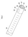
- Fig. 3 is a perspective view showing a hard tip part of an insertion part of the endoscope;
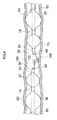
- Fig. 4 is a sectional view schematically illustrating an example of treatment by means of two endoscope devices;
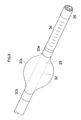
- Fig. 5 is a perspective view showing the tip of the insertion part provided with a first balloon;
- Fig. 6 is a sectional side view showing the tip part of an overtube into which the insertion part is inserted; and
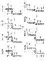
- Figs. 7A to 7H are illustrations showing an operating method for the endoscope device shown in Fig. 1.
-
- The preferred embodiments of an endoscope system and an operation method for the endoscope according to the present invention are described below with reference to accompanying drawings.
- Fig. 1 is a figure showing a configuration of an endoscope device of an endoscope system according to a present embodiment. The
endoscope device 1 shown in the figure comprises anendoscope 10, an overtube (corresponding to an insertion assisting tool) 50, and aballoon control device 100. The endoscope system according to the embodiment is, as shown in Fig. 2, provided with twoendoscope devices 1 shown in Fig. 1, in which system twoendoscope devices reference character 1A, and an endoscope device (a second endoscope device) at the right-hand side is designated byreference character 1B. In Fig. 2, theovertube 50 and theballoon control device 100 are omitted in order to avoid duplication as they are shown in Fig. 1. - In Fig. 1, the
endoscope 10 is provided with ahand operation part 14 and aninsertion part 12 continuously connected to thehand operation part 14. Auniversal cable 15 is connected to thehand operation part 14, and at the tip of theuniversal cable 15, aconnector 17 which is connected to alight source device 150 shown in Fig. 2 and to a processor (not shown), is provided. Thelight source device 150 will be described below. - In the
hand operation part 14 in Fig. 1, an air andwater supply button 16, a suction button 18, and a shutter button 20, which are operated by an operator, are arranged side by side, while a pair ofangle knobs 22 and aforceps insertion section 24 are provided at predetermined positions, respectively. Thehand operation part 14 is further provided with a balloonair supply port 26 for supplying and sucking air into and from afirst balloon 30 in a position with no interference for the operation. - The
insertion part 12 comprises asoft part 32 constituting substantially the whole length of theinsertion part 12, acurved part 34 connected to the tip of thesoft part 32 and ahard tip part 36 connected to the tip of thecurved part 34. Thecurved part 34 is constituted by bendably connecting a plurality of nodal rings and is remotely and curvilinearly operated by a wire (not shown) which is pushed and pulled by rotating operation of the pair ofangle knobs 22 provided for thehand operation part 14. Thereby, atip surface 37 of thehard tip part 36 can be directed toward a desired direction, such as the observation direction of diseased part. - As shown in Fig. 3, the
tip surface 37 of thehard tip part 36 is provided with an objectiveoptical system 38 at a slightly upper part of the central part of the tip surface. Also,illumination lenses 40 are arranged on both right and left sides of the objectiveoptical system 38, and an air andwater supply nozzle 42 and a forceps opening 44, etc. are further provided in a predetermined position under the objectiveoptical system 38. - An observation image taken through the objective
optical system 38, the optical path of which observation image is refracted by 90° by a prism (not shown), is formed on a solid state image pickup element (image pickup device) 39 arranged at an image forming position of the objectiveoptical system 38. From the solid stateimage pickup element 39, an electric signal for displaying the observation image is outputted. The electric signal is transmitted to a signal line wired from theinsertion part 12 through thehand operation part 14 and theuniversal cable 15, which are shown in Fig. 1, and outputted to a processor (not shown) through theconnector 17 shown in Fig. 2. The processor is provided with a video signal processing section which performs conversion processing of the electric signal to a video signal, and outputs the video signal subjected to the conversion processing to a monitor (display device) 152. As a result, the observation image is displayed on adisplay screen 154 of themonitor 152. - In addition, the endoscope system according to the present embodiment is configured such that the observation images imaged by two
endoscope devices single monitor 152. For this reason, thedisplay screen 154 of themonitor 152 is divided into two display screens and is set to display a picture of theendoscope device 1A on one of the two display screens and a picture of theendoscope device 1B on the other display screen. The size of the display screen can be properly changed by a picture size adjustment command signal from a system controller (control device) 156. For example, the display size of the observation image of a preferential endoscope device between theendoscope devices - The
system controller 156 comprises a CPU for generally controlling the whole endoscope system, and a program for performing dimming control of illumination light based on the light quantity detected by theendoscope devices image pickup element 39 is built in a ROM. A program for controlling, in accordance with a situation, the internal pressure of all the balloons which will be explained in the present embodiment, is also built in the ROM. - The
illumination lenses 40 shown in Fig. 3 are lenses for irradiating illumination light to an observation part. The illumination light is sent from a xenon lamp (illumination device) 158 of high-luminance built in thelight source device 150 in Fig. 2 to theillumination lenses 40 via a light guide (not shown). Light quantity of the illumination light from thexenon lamp 158 is controlled so as to be reduced by a lightquantity adjusting mechanism 160 such as a diaphragm device, and the size of the diaphragm aperture of the lightquantity adjusting mechanism 160 is controlled by an adjustingmechanism control section 162 controlled by thesystem controller 156. Thesystem controller 156 also controls the adjustingmechanism control section 162 based on a light quantity detection signal from a lightquantity detecting section 164 built in thelight source device 150. The lightquantity detecting section 164 detects an electric signal of luminance signal level transmitted from the solid stateimage pickup element 39 to the processor, and the detected luminance signal level value is outputted to thesystem controller 156. A saturation luminance signal level value of the solid stateimage pickup element 39 is stored in a RAM of thesystem controller 156. For example, when the luminance signal level value detected at the side of theendoscope device 1A reaches a saturation luminance signal level value, thesystem controller 156 controls the adjustingmechanism control section 162 of theendoscope device 1B so as to make light quantity of the illumination light reduced or to make the illumination stopped at the side of theendoscope device 1B. Thereby, the observation image picked up by theendoscope 1A is displayed again on thedisplay screen 154 of themonitor 152. - When the luminance signal level of the solid state
image pickup element 39, reaches the saturation luminance signal level, the observation image is whitened on thedisplay screen 154 in a manner that halation is generated, and becomes unable to be confirmed, but by performing control so as to reduce light quantity of the illumination light and to stop illumination, a clear observation image can be displayed again. In addition, after performing control so as to reduce light quantity of the illumination light at the side ofendoscope device 1B, the adjustingmechanism control section 162 of theendoscope device 1A is controlled so as to control the lightquantity adjusting mechanism 160 such that the light quantity of theendoscope device 1A becomes an appropriate value, as a result of which the optimal picture can be obtained. - From the forceps opening 44 shown in Fig. 3,
forcipes polyp 170 developed on the inner wall surface of thesmall intestine 70. Theforceps 166 is a clamping forceps for pinching the head of thepolyp 170, andforceps 168 is snare forceps for excising the entrapment of thepolyp 170 with a loop-shaped wire. Theforceps 166 is inserted from theforceps insertion section 24 of theendoscope device 1A, and theforceps 168 is inserted from theforceps insertion section 24 of theendoscope device 1B. Although there may be a case where an endoscope for two channel treatment is used so as to enable theforcipes forceps 166 is used by theendoscope device 1A, andforceps 168 is used by theendoscope device 1B. An example of treatment shown in Fig. 4 is the case where theendoscope device 1A is inserted from the anus, and theendoscope device 1B is inserted from the mouth, each being made to be inserted into the deep part so as to be operated in cooperation with each other. The treatment position is not limited to thesmall intestine 70, but a polyp developed in the caecum and the ascending colon can also be treated by the present endoscope system. Such treatment in the deep part of the intestine using twoendoscope devices endoscope devices - Hereafter, the double balloon type endoscope device will be described.
- As shown in Fig. 1, an air supply/
suction port 28 is formed at a tip outer peripheral face of thesoft part 32, and the air supply/suction opening 28 is communicated with the balloonair supply port 26 via an air supply tube (not shown) with an inner diameter of about 0.8 mm, inserted into theinsertion part 12. Accordingly, when air is supplied to the balloonair supply port 26, air is blown off from the air supply/suction port 28, and conversely, when air is sucked from the balloonair supply port 26, air is sucked from the air supply/suction port 28. - As shown in Fig. 5, the
first balloon 30 made of an elastic material such as rubber is removably mounted at the tip of thesoft part 32. Thefirst balloon 30 is formed of a central swelled part 30C and attaching parts 30A, 30B of the both ends of the central swelled part, and is mounted to the side of thesoft part 32 such that the air supply/suction port 28 is positioned within the swelled part 30C. The attaching parts 30A, 30B formed into a diameter smaller than the diameter of thesoft part 32 are, after being brought into close contact with thesoft part 32 with their resilient force, firmly fixed to the external peripheral surface of thesoft part 32 by a band member (not shown). In the mountedfirst balloon 30, the swelled part 30C is swelled in an approximately spherical shape by air supplied from the air supply/suction port 28. On the contrary, by sucking air from the air supply/suction port 28, the swelled part 30C is contracted so as to be brought into close contact with the external peripheral surface of thesoft part 32. In this way, by mounting thefirst balloon 30 to the tip of thesoft part 32, as shown in Fig. 4, thefirst balloon 30 can be brought into close contact with the intestinal wall, so as to enable the tip end posture of thesoft part 32 to be stabilized. Thereby, thehard tip part 36 can be stabilized in a desired direction by curving operation of thecurved part 34. - The
overtube 50 shown in Fig. 1 is formed of atube body 51 and agripping part 52. As shown in Fig. 6, thetube body 51 is formed into a cylindrical shape having an inner diameter slightly larger than the outer diameter of theinsertion part 12. Thetube body 51 is formed of a flexible urethane resin molding, of which external peripheral surface is provided with a lubricating coat and of which inner peripheral surface is also provided with a lubricating coat. A hard grippingpart 52 shown in Fig. 1 is fitted to thetube body 51 in a watertight state, and thegripping part 52 is detachably connected to thetube body 51. Theinsertion part 12 is inserted from a baseend opening part 52A of thegripping part 52 to thetube body 51.Reference numeral 66 designates a supply port for supplying lubricating water into thetube body 51. - As shown in Fig. 1, a balloon
air supply port 54 is provided at the base end side of thetube body 51. The balloonair supply port 54 is connected with anair supply tube 56 with the inner diameter of about 1 mm, which tube is adhered to the external peripheral surface of thetube body 51 and extended to near atip part 58 of thetube body 51, as shown in Fig. 6. - The
tip part 58 of thetube body 51 is formed to be a tapered shape in order to prevent entanglement of the intestinal wall, etc. The base end side of thetip part 58 of thetube body 51 is fitted with asecond balloon 60 formed of a elastic body, such as rubber. Thesecond balloon 60 is fitted in a state of being penetrated by thetube body 51, and comprises a central swelled part 60C and attaching parts 60A, 60B of the both ends of the central swelled part. The attaching part 60A is folded to the inside of the swelled part 60C, and the folded attaching part 60A is wound with anX-ray contrast thread 62 so as to be fixed to thetube body 51. The attaching part 60B at the side of the base end is arranged outside thesecond balloon 60, and is wound with athread 64 so as to be fixed to thetube body 51. - The swelled part 60C is formed to be an approximately spherical shape in a natural state (state with no expansion and contraction), and the size of the swelled part 60C is formed larger than the size of the
first balloon 30 in a natural state (state with no expansion and contraction). Accordingly, when air is supplied to thefirst balloon 30 and thesecond balloon 60 at the same pressure, the outer diameter of the swelled part 60C of the second balloon becomes larger than the outer diameter of swelled part 30C of thefirst balloon 30. For example, when the outer diameter of thefirst balloon 30 is 25 mm, the outer diameter of thesecond balloon 60 is configured to be 50 mm. - The above described
tube 56 is opened within the swelled part 60C to form an air supply/suction port 57. Thus, when air is supplied from the balloonair supply port 54, air is blown off from the air supply/suction port 57, so as to expand the swelled part 60C. Also, when air is sucked from the balloonair supply port 54, air is sucked from the air supply/suction port 57, so as to contract thesecond balloon 60. - On the other hand, the
balloon control device 100 in Fig. 1 is a device for supplying and sucking fluid such as air to and from thefirst balloon 30, and for supplying and sucking fluid such as air to and from thesecond balloon 60. Theballoon control device 100 comprises adevice body 102 provided with a pump, a sequencer, etc. (not shown), and ahand switch 104 for remote control. - In the front panel of the
device body 102, there are provided a power switch SW1, a stop switch SW2, apressure indicator 106 for thefirst balloon 30, and apressure indicator 108 for thesecond balloon 60. Also, in the front panel of thedevice body 102, there are mounted atube 110 for supplying and sucking air to and from thefirst balloon 30, and atube 120 for supplying and sucking air to and from thesecond balloon 60. In the middle of each of thetubes liquid storage tanks - On the other hand, for the
hand switch 104 there are provided a stop switch SW3 similar to the stop switch SW2 at the side of thedevice body 102, an ON/OFF switch SW4 for causing pressurization/depressurization of thefirst balloon 30, a pause switch SW5 for keeping pressure of thefirst balloon 30, an ON/OFF switch SW6 for causing pressurization/depressurization of thesecond balloon 60 and a pause switch SW7 for keeping pressure of thesecond balloon 60. Thehand switch 104 is electrically connected to thedevice body 102 via acable 150. - The
balloon control device 100 constituted in this way, supplies air to thefirst balloon 30 and thesecond balloon 60 to expand them, and controls the air pressure to a fixed value to keep thefirst balloon 30 and thesecond balloon 60 in the expanded state. Theballoon control device 100 also sucks air from thefirst balloon 30 and thesecond balloon 60 to contract them, and controls the air pressure to a fixed value to keep thefirst balloon 30 and thesecond balloon 60 in the contracted state. - Next, the operation method of the
endoscope device 1B inserted from the mouth of a patient is explained with reference to Figs. 7A to 7H. - First, as shown in Fig. 7A, in a state where the
overtube 50 covers theinsertion part 12, theinsertion part 12 is inserted into the small intestine (for example, the duodenum descending limb) 70. At this time, thefirst balloon 30 and thesecond balloon 60 are contracted. - Then, as shown in Fig. 7B, in a state where the
tip part 58 of theovertube 50 is inserted to a bent part of theintestinal canal 70, thesecond balloon 60 is supplied with air so as to be expanded. Thereby, thesecond balloon 60 is stopped by theintestinal canal 70, and thetip part 58 of theovertube 50 is fixed to theintestinal canal 70. - Next, as shown in Fig. 7C, only the
insertion part 12 of theendoscope 10 is inserted into the deep part of thesmall intestine 70. Then, as shown in Fig. 7D, thefirst balloon 30 is supplied with air so as to be expanded. Thereby, thefirst balloon 30 is fixed to thesmall intestine 70. Since the size of the first balloon at the time of expansion is smaller than that of thesecond balloon 60, thefirst balloon 30 imposes a small amount of burden on thesmall intestine 70, so as to enable the damage of thesmall intestine 70 to be prevented. - Subsequently, after contracting the
second balloon 60 by sucking air therefrom, as shown in Fig. 7E, theovertube 50 is pushed in so as to be inserted along theinsertion part 12. Then, after thetip part 58 of theovertube 50 is pushed in near thefirst balloon 30, as shown in Fig. 7F, thesecond balloon 60 is supplied with air so as to be expanded. Thereby, thesecond balloon 60 is fixed to thesmall intestine 70. That is, thesmall intestine 70 is grasped by thesecond balloon 60. - Next, the
overtube 50 is pulling in as shown in Fig. 7G. Thereby, thesmall intestine 70 is contracted substantially straightly so that excessive deflection and bending of theovertube 50 are eliminated. When theovertube 50 is pulled in, both thefirst balloon 30 and thesecond balloon 60 are restrained by thesmall intestine 70, but the frictional resistance of thefirst balloon 30 is smaller than the frictional resistance of thesecond balloon 60. Accordingly, even when thefirst balloon 30 and thesecond balloon 60 are moved so as to be relatively separated from each other, since thefirst balloon 30 with a small frictional resistance slides with respect to thesmall intestine 70, thesmall intestine 70 is not damaged by being pulled by both theballoons - Subsequently, as shown in Fig. 7H, air is sucked from the
first balloon 30 so as to contract thefirst balloon 30. Thehard tip part 36 of theinsertion part 12 is then inserted into the deep part of thesmall intestine 70 as much as possible. That is, the insertion operation shown in Fig. 7C is performed again. Thereby, thehard tip part 36 of theinsertion part 12 can be inserted into the deep part of thesmall intestine 70. In the case where theinsertion part 12 is further inserted into the deep part, following the fixing operation as shown in Fig. 7D, the pushing-in operation as shown in Fig. 7E, the grasping operation as shown in Fig. 7F, the pulling-in operation as shown in Fig. 7G and the inserting operation as shown in Fig. 7H, may be repeatedly performed in this order. Thereby, theinsertion part 12 can be further inserted into the deep part of thesmall intestine 70, and as shown in Fig. 4, thehard tip part 36 of theinsertion part 12 can be located in the targeted deep part of the small intestine. - On the other hand, the
insertion part 12 of theendoscope device 1A inserted from the anus of the patient is also inserted into the deep part by the same operation method as theendoscope device 1B, so as to enable thehard tip part 36 to be located in the targeted deep part of the small intestine via the rectum and the large intestine. At this time, both of the second balloons 60, 60 (the second balloon for theendoscope device 1A, the fourth balloon for theendoscope device 1B) are expanded so as to assure the treatment space, and both of thefirst balloons 30, 30 (the first balloon for theendoscope device 1A, the third balloon for theendoscope device 1B) are expanded so as to enable thehard tip part 36 of theinsertion part 12 to be stably directed to a desired direction by thecurved part 34. - Incidentally, in the case where a same diseased part is treated by both the
endoscope devices image pickup element 39 of theendoscope device 1A detects illumination light from thexenon lamp 158, which is irradiated from theillumination lens 40 of theendoscope device 1B, thesystem controller 156 performs control so as to reduce light quantity of thexenon lamp 158 of theendoscope device 1B based on the level of luminance signal outputted from the solid stateimage pickup element 39 of theendoscope device 1A. That is, when a signal of the saturation luminance level is outputted from the solid stateimage pickup element 39 of theendoscope device 1A, the lightquantity adjusting mechanism 160 performs control so as to reduce light quantity of the illumination light from thexenon lamp 158 of theendoscope device 1B. Then, the adjustingmechanism control section 162 of theendoscope device 1A is controlled, so that the lightquantity adjusting mechanism 160 is controlled to allow light quantity of theendoscope device 1A to become an appropriate value, thereby enabling an optimum picture of theendoscope device 1A to be obtained. - Also, when the solid state
image pickup element 39 of theendoscope device 1B detects illumination light from thexenon lamp 158, which is irradiated from theillumination lens 40 ofendoscope device 1A, thesystem controller 156 performs control so as to reduce light quantity of thexenon lamp 158 of theendoscope device 1A based on the level of luminance signal outputted from the solid stateimage pickup element 39 of theendoscope device 1B. That is, when a signal of the saturation luminance level is outputted from the solid stateimage pickup element 39 of theendoscope device 1B, the lightquantity adjusting mechanism 160 performs control so as to reduce light quantity of the illumination light from thexenon lamp 158 of theendoscope device 1A. Then, the adjustingmechanism control section 162 of theendoscope device 1B is controlled, so that the lightquantity adjusting mechanism 160 is controlled to allow light quantity of theendoscope device 1B to become an appropriate value, thereby enabling an optimum picture of theendoscope device 1B to be obtained. - Consequently, according to the endoscope system of the present embodiment, a good observation image can be displayed in the
monitor 152 without each of theendoscope devices - The light quantity of the illumination light to be reduced, which is not restricted in particular, may be set in accordance with the dynamic range of the solid state
image pickup element 39. The dimming control may also be performed so as to stop the illumination light. In this case, it is preferred to specify in thesystem controller 156 the endoscope device having priority, such that the illumination light of the endoscope device having priority is not stopped and the illumination light of the endoscope device without priority is stopped.
Claims (4)
- An endoscope system, characterized by comprising:a first endoscope device (1A) provided with an endoscope (10) in which an illumination device (40, 150, 158), an image pickup device (38, 39) and a first balloon (30) are attached to a tip part of an insertion part (12) of the endoscope (10), and with an insertion assisting tool (50, 51, 52) into which the insertion part (12) of the endoscope (10) is inserted, which assists insertion of the insertion part (12) into a body cavity, and to a tip part of which a second balloon (60) is attached;a second endoscope device (1B) provided with an endoscope (10) in which an illumination device (40, 150, 158), an image pickup device (38, 39) and a first balloon (30) are attached to a tip part of an insertion part (12) of the endoscope (10), and with an insertion assisting tool (50, 51, 52) into which the insertion part (12) of the endoscope (10) is inserted, which assists insertion of the insertion (12) part into a body cavity, and to a tip part of which a second balloon (60) is attached;a display device (152) for displaying an object image photographed by an image pickup device (38, 39) of each of the first endoscope device (1A) and the second endoscope device (1B); anda control device (156, 160, 162, 164) for controlling light quantity of one of the illumination devices (40, 158), based on a level of luminance signal outputted from a solid state image pickup element (39) of the image pickup device (38, 39) of the first endoscope device (1A), when the image pickup device (38, 39) detects illumination light irradiated from the illumination device (40, 158) of the second endoscope device (1B), or based on a level of luminance signal outputted from a solid state image pickup element (39) of the image pickup device of the second endoscope device, when the image pickup device (38, 39) detects illumination light irradiated from the illumination device (40, 158) of the first endoscope device (1A).
- The endoscope system according to claim 1, wherein the control device (156, 160, 162, 164) performs control so as to reduce light quantity of the second endoscope device (1B) when the luminance signal level from the solid state image pickup element (39) of the first endoscope device (1A) reaches a saturation luminance signal level, or performs control so as to reduce light quantity of the first endoscope device (1A) when the luminance signal level from the solid state image pickup element (39) of the second endoscope device (1B) reaches a saturation luminance signal level.
- An operation method of endoscopes comprisingcharacterized in that treatment is performed by the first endoscope device (1A) and the second endoscope device (1B).a first endoscope device (1A) provided with an endoscope (10) and an insertion assisting tool (50, 51, 52) into which an insertion part (12) of the endoscope (10) is inserted and which assists insertion of the insertion part (12) into a body cavity, anda second endoscope device (1B) provided with an endoscope (10) and an insertion assisting tool (50, 51, 52) into which an insertion part (12) of the endoscope (10) is inserted and which assists insertion of the insertion part (12) into a body cavity, comprising the steps of:inserting the first endoscope device (1A) from the mouth of a patient; andinserting the second endoscope device (1B) from the anus of the patient,
- The operation method of endoscopes according to claim 3,
wherein an expandable and contractible first balloon (30) is provided at a tip part of the insertion part of the endoscope (10) of the first endoscope device (1A) and a second balloon (60) is provided at a tip part of the insertion assisting tool (50, 51, 52) of the first endoscope device (1A),
wherein an expandable and contractible third balloon (30) is provided at a tip part of the insertion part (12) of the endoscope (10) of the second endoscope device (1B) and a fourth balloon (60) is provided at a tip part of the insertion assisting tool (50, 51, 52) of the second endoscope device (1B), and
wherein the insertion parts (12) of the endoscopes (10) are inserted while expanding and contracting the first to fourth balloons (30, 60).
Applications Claiming Priority (4)
| Application Number | Priority Date | Filing Date | Title |
|---|---|---|---|
| JP2004056219 | 2004-03-01 | ||
| JP2004056219 | 2004-03-01 | ||
| JP2004322799 | 2004-11-05 | ||
| JP2004322799A JP3806934B2 (en) | 2004-03-01 | 2004-11-05 | Endoscope system |
Publications (2)
| Publication Number | Publication Date |
|---|---|
| EP1570778A1 true EP1570778A1 (en) | 2005-09-07 |
| EP1570778B1 EP1570778B1 (en) | 2014-06-04 |
Family
ID=34752185
Family Applications (1)
| Application Number | Title | Priority Date | Filing Date |
|---|---|---|---|
| EP05251093.0A Not-in-force EP1570778B1 (en) | 2004-03-01 | 2005-02-24 | Endoscope system |
Country Status (5)
| Country | Link |
|---|---|
| US (2) | US7585276B2 (en) |
| EP (1) | EP1570778B1 (en) |
| JP (1) | JP3806934B2 (en) |
| CN (1) | CN100443040C (en) |
| ES (1) | ES2472270T3 (en) |
Cited By (11)
| Publication number | Priority date | Publication date | Assignee | Title |
|---|---|---|---|---|
| EP1844700A1 (en) * | 2006-04-13 | 2007-10-17 | Fujinon Corporation | Endoscope with balloon |
| WO2007136879A2 (en) * | 2006-05-19 | 2007-11-29 | Avantis Medical Systems, Inc. | System and method for producing and improving images |
| EP1886634A1 (en) * | 2005-05-31 | 2008-02-13 | Olympus Medical Systems Corp. | Device and method for mucosal detachment |
| US8182422B2 (en) | 2005-12-13 | 2012-05-22 | Avantis Medical Systems, Inc. | Endoscope having detachable imaging device and method of using |
| US8235887B2 (en) | 2006-01-23 | 2012-08-07 | Avantis Medical Systems, Inc. | Endoscope assembly with retroscope |
| US8287446B2 (en) | 2006-04-18 | 2012-10-16 | Avantis Medical Systems, Inc. | Vibratory device, endoscope having such a device, method for configuring an endoscope, and method of reducing looping of an endoscope |
| US8289381B2 (en) | 2005-01-05 | 2012-10-16 | Avantis Medical Systems, Inc. | Endoscope with an imaging catheter assembly and method of configuring an endoscope |
| US8797392B2 (en) | 2005-01-05 | 2014-08-05 | Avantis Medical Sytems, Inc. | Endoscope assembly with a polarizing filter |
| US8872906B2 (en) | 2005-01-05 | 2014-10-28 | Avantis Medical Systems, Inc. | Endoscope assembly with a polarizing filter |
| US9044185B2 (en) | 2007-04-10 | 2015-06-02 | Avantis Medical Systems, Inc. | Method and device for examining or imaging an interior surface of a cavity |
| US11877722B2 (en) | 2009-12-15 | 2024-01-23 | Cornell University | Method and apparatus for manipulating the side wall of a body lumen or body cavity |
Families Citing this family (35)
| Publication number | Priority date | Publication date | Assignee | Title |
|---|---|---|---|---|
| JP3981364B2 (en) * | 2004-03-19 | 2007-09-26 | オリンパス株式会社 | Double balloon endoscope system |
| US10646109B1 (en) * | 2004-07-19 | 2020-05-12 | Hypermed Imaging, Inc. | Device and method of balloon endoscopy |
| JP2006115964A (en) * | 2004-10-20 | 2006-05-11 | Fujinon Corp | Electronic endoscope apparatus |
| JP2007289581A (en) * | 2006-04-27 | 2007-11-08 | Pentax Corp | Endoscopic light source device |
| US20080064931A1 (en) * | 2006-06-13 | 2008-03-13 | Intuitive Surgical, Inc. | Minimally invasive surgical illumination |
| JP2008086697A (en) * | 2006-10-05 | 2008-04-17 | Pentax Corp | Endoscopic treatment tool and endoscope system |
| US20080281159A1 (en) * | 2007-05-08 | 2008-11-13 | University Of Washington | Coordinating image acquisition among multiple endoscopes |
| JP5128847B2 (en) * | 2007-05-22 | 2013-01-23 | オリンパスメディカルシステムズ株式会社 | Endoscope |
| JP5114170B2 (en) * | 2007-11-22 | 2013-01-09 | オリンパスメディカルシステムズ株式会社 | Endoscope system |
| US20100069710A1 (en) * | 2008-09-02 | 2010-03-18 | Ken Yamatani | treatment method |
| US10149601B2 (en) | 2009-12-15 | 2018-12-11 | Lumendi Ltd. | Method and apparatus for manipulating the side wall of a body lumen or body cavity so as to provide increased visualization of the same and/or increased access to the same, and/or for stabilizing instruments relative to the same |
| WO2011084490A1 (en) | 2009-12-15 | 2011-07-14 | Cornell University | Method and apparatus for stabilizing, straightening, or expanding the wall of a lumen or cavity |
| US10485401B2 (en) | 2009-12-15 | 2019-11-26 | Lumendi Ltd. | Method and apparatus for manipulating the side wall of a body lumen or body cavity so as to provide increased visualization of the same and/or increased access to the same, and/or for stabilizing instruments relative to the same |
| US9986893B2 (en) | 2009-12-15 | 2018-06-05 | Cornell University | Method and apparatus for manipulating the side wall of a body lumen or body cavity so as to provide increased visualization of the same and/or increased access to the same, and/or for stabilizing instruments relative to the same |
| JP5425695B2 (en) * | 2010-04-15 | 2014-02-26 | 幹人 黒田 | Endoscope device |
| US20130116549A1 (en) * | 2010-10-18 | 2013-05-09 | Erhan H. Gunday | Anchored Working Channel |
| US20120095292A1 (en) | 2010-10-18 | 2012-04-19 | Gunday Erhan H | Anchored Guidewire |
| CN102065605B (en) * | 2010-11-02 | 2012-12-19 | 重庆金山科技(集团)有限公司 | Light resource device and lamp service life detection method for endoscope |
| JP5331904B2 (en) * | 2011-04-15 | 2013-10-30 | 富士フイルム株式会社 | Endoscope system and method for operating endoscope system |
| US8878920B2 (en) | 2011-07-12 | 2014-11-04 | Karl Storz Imaging, Inc. | Method and apparatus for protection from high intensity light |
| EP2740398A4 (en) * | 2012-02-15 | 2015-05-27 | Olympus Medical Systems Corp | Medical system |
| FR3015055B1 (en) * | 2013-12-17 | 2017-03-03 | Univ Tech De Compiegne - Utc | DOUBLE IMAGE GUIDE 3D ENDOSCOPE FOR STRUCTURED LIGHT DELIVERY |
| KR102353576B1 (en) * | 2014-02-11 | 2022-01-19 | 코넬 유니버시티 | Method and apparatus for manipulating the side wall of a body lumen or body cavity so as to provide increased visualization of the same and/or increased access to the same, and/or for stabilizing instruments relative to the same |
| CN104622561B (en) * | 2014-09-12 | 2017-08-25 | 密雷 | A kind of minimally invasive guarantor's courage operation endoscope system |
| JP6597635B2 (en) * | 2014-12-09 | 2019-10-30 | ソニー株式会社 | Illumination device, method of operating illumination device, and image acquisition system |
| JP6368256B2 (en) * | 2015-02-05 | 2018-08-01 | 富士フイルム株式会社 | Endoscope system |
| US11553832B2 (en) * | 2015-06-05 | 2023-01-17 | Fujifilm Corporation | Endoscope system |
| US10448805B2 (en) | 2015-09-28 | 2019-10-22 | Bio-Medical Engineering (HK) Limited | Endoscopic systems, devices and methods |
| US10765304B2 (en) * | 2015-09-28 | 2020-09-08 | Bio-Medical Engineering (HK) Limited | Endoscopic systems, devices, and methods for performing in vivo procedures |
| US10136799B2 (en) | 2015-09-28 | 2018-11-27 | Bio-Medical Engineering (HK) Limited | Endoscopic systems, devices, and methods |
| JP2018015282A (en) * | 2016-07-28 | 2018-02-01 | オリンパス株式会社 | Endoscope system and endoscope system controller |
| EP3823513A4 (en) * | 2018-07-16 | 2022-08-17 | Lumendi Ltd. | Method and apparatus for manipulating the side wall of a body lumen or body cavity so as to provide increased visualization of the same and/or increased access to the same and/or for stabilizing instruments relative to the same |
| CN109247905B (en) * | 2018-10-29 | 2022-05-06 | 重庆金山医疗技术研究院有限公司 | Method for judging whether light guide part is pulled out from host machine by endoscope system and endoscope system |
| CN109770825B (en) * | 2019-03-06 | 2021-09-24 | 杭州行开医学影像技术有限公司 | Endoscope with 3D imaging function |
| CN110613424B (en) * | 2019-10-31 | 2021-09-21 | 四川省人民医院 | Painless intelligent anorectal examination instrument |
Citations (6)
| Publication number | Priority date | Publication date | Assignee | Title |
|---|---|---|---|---|
| US4622584A (en) * | 1983-09-05 | 1986-11-11 | Olympus Optical Co., Ltd. | Automatic dimmer for endoscope |
| US5196928A (en) * | 1991-04-02 | 1993-03-23 | Olympus Optical Co., Ltd. | Endoscope system for simultaneously displaying two endoscopic images on a shared monitor |
| US5398056A (en) | 1992-02-27 | 1995-03-14 | Olympus Optical Co., Ltd. | Endoscope system |
| JP2000356749A (en) | 1999-06-15 | 2000-12-26 | Olympus Optical Co Ltd | Endoscope device |
| JP2001340462A (en) | 2000-06-05 | 2001-12-11 | Hironori Yamamoto | Tube with balloons for assisting insertion of endoscope |
| JP2002301019A (en) | 2001-04-09 | 2002-10-15 | Hironori Yamamoto | Endoscope |
Family Cites Families (15)
| Publication number | Priority date | Publication date | Assignee | Title |
|---|---|---|---|---|
| US4040413A (en) * | 1974-07-18 | 1977-08-09 | Fuji Photo Optical Co. Ltd. | Endoscope |
| US4224929A (en) * | 1977-11-08 | 1980-09-30 | Olympus Optical Co., Ltd. | Endoscope with expansible cuff member and operation section |
| US4198981A (en) * | 1978-03-27 | 1980-04-22 | Manfred Sinnreich | Intrauterine surgical device |
| WO1989000829A1 (en) * | 1987-07-23 | 1989-02-09 | Terumo Kabushiki Kaisha | Catheter tube |
| US5645519A (en) * | 1994-03-18 | 1997-07-08 | Jai S. Lee | Endoscopic instrument for controlled introduction of tubular members in the body and methods therefor |
| US6270477B1 (en) * | 1996-05-20 | 2001-08-07 | Percusurge, Inc. | Catheter for emboli containment |
| JP3798871B2 (en) | 1997-03-12 | 2006-07-19 | オリンパス株式会社 | Endoscope system |
| US6398775B1 (en) * | 1999-10-21 | 2002-06-04 | Pulmonx | Apparatus and method for isolated lung access |
| JP2002098913A (en) | 2000-09-22 | 2002-04-05 | Olympus Optical Co Ltd | Endoscope apparatus |
| JP2003204920A (en) * | 2002-01-11 | 2003-07-22 | Olympus Optical Co Ltd | Insertion assisting tool |
| US20030187330A1 (en) * | 2002-03-28 | 2003-10-02 | Fuji Photo Optical Co., Ltd. | Electronic endoscope apparatus using micromirror device |
| US20040186349A1 (en) * | 2002-12-24 | 2004-09-23 | Usgi Medical Corp. | Apparatus and methods for achieving endoluminal access |
| US20050059931A1 (en) * | 2003-09-16 | 2005-03-17 | Venomatrix | Methods and apparatus for localized and semi-localized drug delivery |
| US20060036267A1 (en) * | 2004-08-11 | 2006-02-16 | Usgi Medical Inc. | Methods and apparatus for performing malabsorptive bypass procedures within a patient's gastro-intestinal lumen |
| JP2007014475A (en) * | 2005-07-06 | 2007-01-25 | Fujinon Corp | Balloon control device for endoscope apparatus |
-
2004
- 2004-11-05 JP JP2004322799A patent/JP3806934B2/en not_active Expired - Fee Related
-
2005
- 2005-02-24 ES ES05251093.0T patent/ES2472270T3/en active Active
- 2005-02-24 EP EP05251093.0A patent/EP1570778B1/en not_active Not-in-force
- 2005-03-01 CN CNB2005100525481A patent/CN100443040C/en not_active Expired - Fee Related
- 2005-03-01 US US11/068,433 patent/US7585276B2/en not_active Expired - Fee Related
-
2009
- 2009-07-22 US US12/507,535 patent/US20090287051A1/en not_active Abandoned
Patent Citations (6)
| Publication number | Priority date | Publication date | Assignee | Title |
|---|---|---|---|---|
| US4622584A (en) * | 1983-09-05 | 1986-11-11 | Olympus Optical Co., Ltd. | Automatic dimmer for endoscope |
| US5196928A (en) * | 1991-04-02 | 1993-03-23 | Olympus Optical Co., Ltd. | Endoscope system for simultaneously displaying two endoscopic images on a shared monitor |
| US5398056A (en) | 1992-02-27 | 1995-03-14 | Olympus Optical Co., Ltd. | Endoscope system |
| JP2000356749A (en) | 1999-06-15 | 2000-12-26 | Olympus Optical Co Ltd | Endoscope device |
| JP2001340462A (en) | 2000-06-05 | 2001-12-11 | Hironori Yamamoto | Tube with balloons for assisting insertion of endoscope |
| JP2002301019A (en) | 2001-04-09 | 2002-10-15 | Hironori Yamamoto | Endoscope |
Non-Patent Citations (3)
| Title |
|---|
| PATENT ABSTRACTS OF JAPAN vol. 2000, no. 15 6 April 2001 (2001-04-06) * |
| PATENT ABSTRACTS OF JAPAN vol. 2002, no. 04 4 August 2002 (2002-08-04) * |
| PATENT ABSTRACTS OF JAPAN vol. 2003, no. 02 5 February 2003 (2003-02-05) * |
Cited By (22)
| Publication number | Priority date | Publication date | Assignee | Title |
|---|---|---|---|---|
| US8289381B2 (en) | 2005-01-05 | 2012-10-16 | Avantis Medical Systems, Inc. | Endoscope with an imaging catheter assembly and method of configuring an endoscope |
| US8872906B2 (en) | 2005-01-05 | 2014-10-28 | Avantis Medical Systems, Inc. | Endoscope assembly with a polarizing filter |
| US8797392B2 (en) | 2005-01-05 | 2014-08-05 | Avantis Medical Sytems, Inc. | Endoscope assembly with a polarizing filter |
| US9289236B2 (en) | 2005-05-31 | 2016-03-22 | Olympus Corporation | Mucosa separation apparatus, and method for mucosa separation |
| EP1886634A1 (en) * | 2005-05-31 | 2008-02-13 | Olympus Medical Systems Corp. | Device and method for mucosal detachment |
| EP1886634A4 (en) * | 2005-05-31 | 2014-03-19 | Olympus Medical Systems Corp | Device and method for mucosal detachment |
| US8182422B2 (en) | 2005-12-13 | 2012-05-22 | Avantis Medical Systems, Inc. | Endoscope having detachable imaging device and method of using |
| US11529044B2 (en) | 2005-12-13 | 2022-12-20 | Psip Llc | Endoscope imaging device |
| US8235887B2 (en) | 2006-01-23 | 2012-08-07 | Avantis Medical Systems, Inc. | Endoscope assembly with retroscope |
| US10045685B2 (en) | 2006-01-23 | 2018-08-14 | Avantis Medical Systems, Inc. | Endoscope |
| EP1844700A1 (en) * | 2006-04-13 | 2007-10-17 | Fujinon Corporation | Endoscope with balloon |
| US8409078B2 (en) | 2006-04-13 | 2013-04-02 | Fujifilm Corporation | Endoscope |
| US8287446B2 (en) | 2006-04-18 | 2012-10-16 | Avantis Medical Systems, Inc. | Vibratory device, endoscope having such a device, method for configuring an endoscope, and method of reducing looping of an endoscope |
| US8197399B2 (en) | 2006-05-19 | 2012-06-12 | Avantis Medical Systems, Inc. | System and method for producing and improving images |
| US8587645B2 (en) | 2006-05-19 | 2013-11-19 | Avantis Medical Systems, Inc. | Device and method for reducing effects of video artifacts |
| US8310530B2 (en) | 2006-05-19 | 2012-11-13 | Avantis Medical Systems, Inc. | Device and method for reducing effects of video artifacts |
| WO2007136879A3 (en) * | 2006-05-19 | 2008-01-31 | Avantis Medical Systems Inc | System and method for producing and improving images |
| WO2007136879A2 (en) * | 2006-05-19 | 2007-11-29 | Avantis Medical Systems, Inc. | System and method for producing and improving images |
| US9044185B2 (en) | 2007-04-10 | 2015-06-02 | Avantis Medical Systems, Inc. | Method and device for examining or imaging an interior surface of a cavity |
| US9613418B2 (en) | 2007-04-10 | 2017-04-04 | Avantis Medical Systems, Inc. | Method and device for examining or imaging an interior surface of a cavity |
| US10354382B2 (en) | 2007-04-10 | 2019-07-16 | Avantis Medical Systems, Inc. | Method and device for examining or imaging an interior surface of a cavity |
| US11877722B2 (en) | 2009-12-15 | 2024-01-23 | Cornell University | Method and apparatus for manipulating the side wall of a body lumen or body cavity |
Also Published As
| Publication number | Publication date |
|---|---|
| EP1570778B1 (en) | 2014-06-04 |
| ES2472270T3 (en) | 2014-06-30 |
| CN1663523A (en) | 2005-09-07 |
| JP3806934B2 (en) | 2006-08-09 |
| CN100443040C (en) | 2008-12-17 |
| US20090287051A1 (en) | 2009-11-19 |
| JP2005279252A (en) | 2005-10-13 |
| US7585276B2 (en) | 2009-09-08 |
| US20050222500A1 (en) | 2005-10-06 |
Similar Documents
| Publication | Publication Date | Title |
|---|---|---|
| EP1570778B1 (en) | Endoscope system | |
| US7537562B2 (en) | Endoscope apparatus | |
| JP5095124B2 (en) | Endoscope | |
| US8273013B2 (en) | Endoscope insertion assistant probe and applicable endoscope apparatus therefor | |
| US7959559B2 (en) | Endoscope insertion assisting device, endoscope apparatus, medical treatment device and endoscope insertion method | |
| EP1884187B1 (en) | Endoscopic insertion aid and endoscopic system | |
| US20080214890A1 (en) | Therapeutic method and therapeutic system used with steps for approaching to lesion using overtube | |
| US20090112060A1 (en) | Medical apparatus | |
| US7833176B2 (en) | Pressure-propelled system for body lumen | |
| JP5116985B2 (en) | Endoscope | |
| JP2002330924A (en) | Endoscope | |
| JP3922217B2 (en) | Endoscope device | |
| JP4491693B2 (en) | Endoscope device | |
| JP5400841B2 (en) | Endoscope system | |
| JP2007330468A (en) | Cover for endoscope and endoscope device furnished with it | |
| JP2005278846A (en) | Endoscope apparatus | |
| JP2023075036A (en) | Medical system and control method of medical system | |
| JP4665671B2 (en) | Endoscope device | |
| KR100848771B1 (en) | Endoscope balloon control device | |
| JP2021027866A (en) | Endoscope apparatus and balloon | |
| JP2005329134A (en) | Endoscope apparatus | |
| JP2008023102A (en) | Endoscope | |
| JP2009160219A (en) | Balloon , balloon endoscope, and balloon fitting method | |
| JP2005245959A (en) | Ultrasonic endoscope apparatus | |
| JP2007260131A (en) | Colonoscope apparatus |
Legal Events
| Date | Code | Title | Description |
|---|---|---|---|
| PUAI | Public reference made under article 153(3) epc to a published international application that has entered the european phase |
Free format text: ORIGINAL CODE: 0009012 |
|
| 17P | Request for examination filed |
Effective date: 20050617 |
|
| AK | Designated contracting states |
Kind code of ref document: A1 Designated state(s): AT BE BG CH CY CZ DE DK EE ES FI FR GB GR HU IE IS IT LI LT LU MC NL PL PT RO SE SI SK TR |
|
| AX | Request for extension of the european patent |
Extension state: AL BA HR LV MK YU |
|
| AKX | Designation fees paid |
Designated state(s): AT BE BG CH CY CZ DE DK EE ES FI FR GB GR HU IE IS IT LI LT LU MC NL PL PT RO SE SI SK TR |
|
| 17Q | First examination report despatched |
Effective date: 20071017 |
|
| GRAP | Despatch of communication of intention to grant a patent |
Free format text: ORIGINAL CODE: EPIDOSNIGR1 |
|
| INTG | Intention to grant announced |
Effective date: 20140113 |
|
| GRAS | Grant fee paid |
Free format text: ORIGINAL CODE: EPIDOSNIGR3 |
|
| RAP1 | Party data changed (applicant data changed or rights of an application transferred) |
Owner name: FUJIFILM CORPORATION |
|
| GRAA | (expected) grant |
Free format text: ORIGINAL CODE: 0009210 |
|
| AK | Designated contracting states |
Kind code of ref document: B1 Designated state(s): AT BE BG CH CY CZ DE DK EE ES FI FR GB GR HU IE IS IT LI LT LU MC NL PL PT RO SE SI SK TR |
|
| REG | Reference to a national code |
Ref country code: GB Ref legal event code: FG4D |
|
| REG | Reference to a national code |
Ref country code: CH Ref legal event code: EP |
|
| REG | Reference to a national code |
Ref country code: AT Ref legal event code: REF Ref document number: 670562 Country of ref document: AT Kind code of ref document: T Effective date: 20140615 |
|
| REG | Reference to a national code |
Ref country code: ES Ref legal event code: FG2A Ref document number: 2472270 Country of ref document: ES Kind code of ref document: T3 Effective date: 20140630 |
|
| REG | Reference to a national code |
Ref country code: IE Ref legal event code: FG4D |
|
| REG | Reference to a national code |
Ref country code: DE Ref legal event code: R096 Ref document number: 602005043778 Country of ref document: DE Effective date: 20140717 |
|
| REG | Reference to a national code |
Ref country code: AT Ref legal event code: MK05 Ref document number: 670562 Country of ref document: AT Kind code of ref document: T Effective date: 20140604 |
|
| REG | Reference to a national code |
Ref country code: NL Ref legal event code: VDEP Effective date: 20140604 |
|
| PG25 | Lapsed in a contracting state [announced via postgrant information from national office to epo] |
Ref country code: CY Free format text: LAPSE BECAUSE OF FAILURE TO SUBMIT A TRANSLATION OF THE DESCRIPTION OR TO PAY THE FEE WITHIN THE PRESCRIBED TIME-LIMIT Effective date: 20140604 Ref country code: GR Free format text: LAPSE BECAUSE OF FAILURE TO SUBMIT A TRANSLATION OF THE DESCRIPTION OR TO PAY THE FEE WITHIN THE PRESCRIBED TIME-LIMIT Effective date: 20140905 Ref country code: LT Free format text: LAPSE BECAUSE OF FAILURE TO SUBMIT A TRANSLATION OF THE DESCRIPTION OR TO PAY THE FEE WITHIN THE PRESCRIBED TIME-LIMIT Effective date: 20140604 Ref country code: FI Free format text: LAPSE BECAUSE OF FAILURE TO SUBMIT A TRANSLATION OF THE DESCRIPTION OR TO PAY THE FEE WITHIN THE PRESCRIBED TIME-LIMIT Effective date: 20140604 |
|
| REG | Reference to a national code |
Ref country code: LT Ref legal event code: MG4D |
|
| PG25 | Lapsed in a contracting state [announced via postgrant information from national office to epo] |
Ref country code: AT Free format text: LAPSE BECAUSE OF FAILURE TO SUBMIT A TRANSLATION OF THE DESCRIPTION OR TO PAY THE FEE WITHIN THE PRESCRIBED TIME-LIMIT Effective date: 20140604 Ref country code: SE Free format text: LAPSE BECAUSE OF FAILURE TO SUBMIT A TRANSLATION OF THE DESCRIPTION OR TO PAY THE FEE WITHIN THE PRESCRIBED TIME-LIMIT Effective date: 20140604 |
|
| PG25 | Lapsed in a contracting state [announced via postgrant information from national office to epo] |
Ref country code: PT Free format text: LAPSE BECAUSE OF FAILURE TO SUBMIT A TRANSLATION OF THE DESCRIPTION OR TO PAY THE FEE WITHIN THE PRESCRIBED TIME-LIMIT Effective date: 20141006 Ref country code: EE Free format text: LAPSE BECAUSE OF FAILURE TO SUBMIT A TRANSLATION OF THE DESCRIPTION OR TO PAY THE FEE WITHIN THE PRESCRIBED TIME-LIMIT Effective date: 20140604 Ref country code: SK Free format text: LAPSE BECAUSE OF FAILURE TO SUBMIT A TRANSLATION OF THE DESCRIPTION OR TO PAY THE FEE WITHIN THE PRESCRIBED TIME-LIMIT Effective date: 20140604 Ref country code: RO Free format text: LAPSE BECAUSE OF FAILURE TO SUBMIT A TRANSLATION OF THE DESCRIPTION OR TO PAY THE FEE WITHIN THE PRESCRIBED TIME-LIMIT Effective date: 20140604 Ref country code: CZ Free format text: LAPSE BECAUSE OF FAILURE TO SUBMIT A TRANSLATION OF THE DESCRIPTION OR TO PAY THE FEE WITHIN THE PRESCRIBED TIME-LIMIT Effective date: 20140604 |
|
| REG | Reference to a national code |
Ref country code: FR Ref legal event code: PLFP Year of fee payment: 11 |
|
| PG25 | Lapsed in a contracting state [announced via postgrant information from national office to epo] |
Ref country code: NL Free format text: LAPSE BECAUSE OF FAILURE TO SUBMIT A TRANSLATION OF THE DESCRIPTION OR TO PAY THE FEE WITHIN THE PRESCRIBED TIME-LIMIT Effective date: 20140604 Ref country code: IS Free format text: LAPSE BECAUSE OF FAILURE TO SUBMIT A TRANSLATION OF THE DESCRIPTION OR TO PAY THE FEE WITHIN THE PRESCRIBED TIME-LIMIT Effective date: 20141004 Ref country code: PL Free format text: LAPSE BECAUSE OF FAILURE TO SUBMIT A TRANSLATION OF THE DESCRIPTION OR TO PAY THE FEE WITHIN THE PRESCRIBED TIME-LIMIT Effective date: 20140604 |
|
| REG | Reference to a national code |
Ref country code: DE Ref legal event code: R097 Ref document number: 602005043778 Country of ref document: DE |
|
| PLBE | No opposition filed within time limit |
Free format text: ORIGINAL CODE: 0009261 |
|
| STAA | Information on the status of an ep patent application or granted ep patent |
Free format text: STATUS: NO OPPOSITION FILED WITHIN TIME LIMIT |
|
| PG25 | Lapsed in a contracting state [announced via postgrant information from national office to epo] |
Ref country code: DK Free format text: LAPSE BECAUSE OF FAILURE TO SUBMIT A TRANSLATION OF THE DESCRIPTION OR TO PAY THE FEE WITHIN THE PRESCRIBED TIME-LIMIT Effective date: 20140604 |
|
| PGFP | Annual fee paid to national office [announced via postgrant information from national office to epo] |
Ref country code: IT Payment date: 20150209 Year of fee payment: 11 Ref country code: ES Payment date: 20150113 Year of fee payment: 11 Ref country code: DE Payment date: 20150218 Year of fee payment: 11 |
|
| 26N | No opposition filed |
Effective date: 20150305 |
|
| PGFP | Annual fee paid to national office [announced via postgrant information from national office to epo] |
Ref country code: FR Payment date: 20150210 Year of fee payment: 11 Ref country code: GB Payment date: 20150218 Year of fee payment: 11 |
|
| REG | Reference to a national code |
Ref country code: DE Ref legal event code: R097 Ref document number: 602005043778 Country of ref document: DE Effective date: 20150305 |
|
| PG25 | Lapsed in a contracting state [announced via postgrant information from national office to epo] |
Ref country code: BE Free format text: LAPSE BECAUSE OF FAILURE TO SUBMIT A TRANSLATION OF THE DESCRIPTION OR TO PAY THE FEE WITHIN THE PRESCRIBED TIME-LIMIT Effective date: 20140604 |
|
| PG25 | Lapsed in a contracting state [announced via postgrant information from national office to epo] |
Ref country code: SI Free format text: LAPSE BECAUSE OF FAILURE TO SUBMIT A TRANSLATION OF THE DESCRIPTION OR TO PAY THE FEE WITHIN THE PRESCRIBED TIME-LIMIT Effective date: 20140604 |
|
| PG25 | Lapsed in a contracting state [announced via postgrant information from national office to epo] |
Ref country code: LU Free format text: LAPSE BECAUSE OF FAILURE TO SUBMIT A TRANSLATION OF THE DESCRIPTION OR TO PAY THE FEE WITHIN THE PRESCRIBED TIME-LIMIT Effective date: 20150224 |
|
| REG | Reference to a national code |
Ref country code: CH Ref legal event code: PL |
|
| PG25 | Lapsed in a contracting state [announced via postgrant information from national office to epo] |
Ref country code: LI Free format text: LAPSE BECAUSE OF NON-PAYMENT OF DUE FEES Effective date: 20150228 Ref country code: MC Free format text: LAPSE BECAUSE OF FAILURE TO SUBMIT A TRANSLATION OF THE DESCRIPTION OR TO PAY THE FEE WITHIN THE PRESCRIBED TIME-LIMIT Effective date: 20140604 Ref country code: CH Free format text: LAPSE BECAUSE OF NON-PAYMENT OF DUE FEES Effective date: 20150228 |
|
| REG | Reference to a national code |
Ref country code: IE Ref legal event code: MM4A |
|
| PG25 | Lapsed in a contracting state [announced via postgrant information from national office to epo] |
Ref country code: IE Free format text: LAPSE BECAUSE OF NON-PAYMENT OF DUE FEES Effective date: 20150224 |
|
| REG | Reference to a national code |
Ref country code: DE Ref legal event code: R119 Ref document number: 602005043778 Country of ref document: DE |
|
| GBPC | Gb: european patent ceased through non-payment of renewal fee |
Effective date: 20160224 |
|
| REG | Reference to a national code |
Ref country code: FR Ref legal event code: ST Effective date: 20161028 |
|
| PG25 | Lapsed in a contracting state [announced via postgrant information from national office to epo] |
Ref country code: IT Free format text: LAPSE BECAUSE OF NON-PAYMENT OF DUE FEES Effective date: 20160224 |
|
| PG25 | Lapsed in a contracting state [announced via postgrant information from national office to epo] |
Ref country code: DE Free format text: LAPSE BECAUSE OF NON-PAYMENT OF DUE FEES Effective date: 20160901 Ref country code: FR Free format text: LAPSE BECAUSE OF NON-PAYMENT OF DUE FEES Effective date: 20160229 Ref country code: GB Free format text: LAPSE BECAUSE OF NON-PAYMENT OF DUE FEES Effective date: 20160224 |
|
| PG25 | Lapsed in a contracting state [announced via postgrant information from national office to epo] |
Ref country code: BG Free format text: LAPSE BECAUSE OF FAILURE TO SUBMIT A TRANSLATION OF THE DESCRIPTION OR TO PAY THE FEE WITHIN THE PRESCRIBED TIME-LIMIT Effective date: 20140604 Ref country code: ES Free format text: LAPSE BECAUSE OF NON-PAYMENT OF DUE FEES Effective date: 20160225 Ref country code: HU Free format text: LAPSE BECAUSE OF FAILURE TO SUBMIT A TRANSLATION OF THE DESCRIPTION OR TO PAY THE FEE WITHIN THE PRESCRIBED TIME-LIMIT; INVALID AB INITIO Effective date: 20050224 |
|
| PG25 | Lapsed in a contracting state [announced via postgrant information from national office to epo] |
Ref country code: TR Free format text: LAPSE BECAUSE OF FAILURE TO SUBMIT A TRANSLATION OF THE DESCRIPTION OR TO PAY THE FEE WITHIN THE PRESCRIBED TIME-LIMIT Effective date: 20140604 |