EP1571510B1 - Intelligent self-determining I/O device - Google Patents
Intelligent self-determining I/O device Download PDFInfo
- Publication number
- EP1571510B1 EP1571510B1 EP05004721A EP05004721A EP1571510B1 EP 1571510 B1 EP1571510 B1 EP 1571510B1 EP 05004721 A EP05004721 A EP 05004721A EP 05004721 A EP05004721 A EP 05004721A EP 1571510 B1 EP1571510 B1 EP 1571510B1
- Authority
- EP
- European Patent Office
- Prior art keywords
- backplane
- data
- module
- circuit
- network
- Prior art date
- Legal status (The legal status is an assumption and is not a legal conclusion. Google has not performed a legal analysis and makes no representation as to the accuracy of the status listed.)
- Active
Links
Images

Classifications
-
- G—PHYSICS
- G05—CONTROLLING; REGULATING
- G05B—CONTROL OR REGULATING SYSTEMS IN GENERAL; FUNCTIONAL ELEMENTS OF SUCH SYSTEMS; MONITORING OR TESTING ARRANGEMENTS FOR SUCH SYSTEMS OR ELEMENTS
- G05B19/00—Programme-control systems
- G05B19/02—Programme-control systems electric
- G05B19/04—Programme control other than numerical control, i.e. in sequence controllers or logic controllers
- G05B19/05—Programmable logic controllers, e.g. simulating logic interconnections of signals according to ladder diagrams or function charts
- G05B19/054—Input/output
-
- G—PHYSICS
- G05—CONTROLLING; REGULATING
- G05B—CONTROL OR REGULATING SYSTEMS IN GENERAL; FUNCTIONAL ELEMENTS OF SUCH SYSTEMS; MONITORING OR TESTING ARRANGEMENTS FOR SUCH SYSTEMS OR ELEMENTS
- G05B2219/00—Program-control systems
- G05B2219/10—Plc systems
- G05B2219/11—Plc I-O input output
- G05B2219/1138—Configuration of I-O
-
- G—PHYSICS
- G05—CONTROLLING; REGULATING
- G05B—CONTROL OR REGULATING SYSTEMS IN GENERAL; FUNCTIONAL ELEMENTS OF SUCH SYSTEMS; MONITORING OR TESTING ARRANGEMENTS FOR SUCH SYSTEMS OR ELEMENTS
- G05B2219/00—Program-control systems
- G05B2219/10—Plc systems
- G05B2219/12—Plc mp multi processor system
- G05B2219/1202—Modules with same hardware and software
-
- G—PHYSICS
- G05—CONTROLLING; REGULATING
- G05B—CONTROL OR REGULATING SYSTEMS IN GENERAL; FUNCTIONAL ELEMENTS OF SUCH SYSTEMS; MONITORING OR TESTING ARRANGEMENTS FOR SUCH SYSTEMS OR ELEMENTS
- G05B2219/00—Program-control systems
- G05B2219/20—Pc systems
- G05B2219/25—Pc structure of the system
- G05B2219/25323—Intelligent modules
Definitions
- the present development relates to an intelligent self-determining input/output (I/O) device and to an industrial automation control system including same.
- Industrial automation control systems comprise an industrial controller, which is a special purpose computer used for controlling industrial processes and manufacturing equipment on a real-time basis. Under the direction of a stored program, the industrial controller examines a set of inputs reflecting the status of the controlled process and changes a set of outputs controlling the industrial process.
- the inputs and outputs may be binary or analog. Typically, analog signals are converted to binary data for processing.
- Industrial controllers differ from conventional computers in that their hardware configurations vary significantly from application to application reflecting their wide range of uses. This variability is accommodated by constructing the industrial controller on a modular basis having removable input and output (I/O) modules that may accommodate different numbers of input and output points depending on the process being controlled.
- I/O input and output
- the need to connect the I/O modules to different pieces of machinery that may be spatially separated has led to the development of distributed I/O systems that take a variety of forms.
- a single discrete or "block" I/O module is located where desired.
- the block I/O module contains digital or analog I/O circuits, a built-in power supply, and a built-in network adapter for communicating with the industrial controller.
- the distributed I/O installation is modular in the sense that a single network adapter module is connected to the data network, and one or more I/O modules, as needed, are connected to the adapter module for communication with the industrial controller through the single network adapter module.
- I/O modules and associated adapter modules must be supplied in numerous different configurations in terms of the electrical connectors, the internal digital/analog I/O circuitry, the enclosure ratings, and the like. As such, it has been deemed desirable to provide an I/O module that functions in both a "block” or stand-alone mode, as well as in a modular mode. This, then, eliminates the need to provide I/O devices in both the block I/O and modular I/O embodiments.
- a memory-programmable controller having a signal-processing intelligence, eg. a microprocessor, and at least one interface for transmitting and/or receiving digital signals having interface connections for the connection of external loads, eg. a bus connection.
- a configurable circuit is arranged between the intelligence and the interface connections.
- a universal input/output device for an industrial automation control system includes a housing; a power supply for connecting to a voltage source; an input/output circuit for communicating with an industrial process; a network adapter circuit for communicating data to and from a data network; a backplane communication circuit for sending backplane data upstream and downstream along a backplane; and, a device setup control circuit that performs an initialization process to configure the device as one of: (i) a stand-along block I/O device; (ii) a network adapter module of a modular I/O device; or (iii) an I/O module of a modular I/O device wherein said device setup control circuit comprises means for sending and receiving backplane test data to adjacent devices via said backplane communication circuit, and wherein said setup control circuit configures said device based upon receipt of an acknowledgement response from an adjacent device via said backplane communication circuit.
- an industrial automation control system comprises at least two intelligent self-determining I/O devices.
- Each of said I/O devices comprises a housing; a power supply for connecting to a voltage source; an input/output circuit for communicating with an industrial process; a network adapter circuit for communicating data to and from a data network; a backplane communication circuit for sending backplane data upstream and downstream along a backplane; and, a device setup control circuit that performs an initialization process to configure said device as one of: (i) a stand-along block I/O device; (ii) a network adapter module of a modular I/O device; or (iii) an I/O module of a modular I/O device wherein said device setup control circuit comprises means for sending and receiving backplane test data to adjacent devices via said backplane communication circuit, and wherein said setup control circuit configures said device based upon receipt of an acknowledgement response from an adjacent device via said backplane communication circuit.
- a method for constructing an industrial automation control system comprises connecting a plurality of intelligent self-determining I/O devices to a data network.
- An initialization routine is performed with each of the intelligent self-determining I/O devices.
- the initialization routine comprises, for each of the intelligent self-determining I/O devices: (a) determining if network data are being received into the device; (b) determining if upstream backplane test data are being received into the device; (c) determining if downstream backplane test data are being received into the device; and, (d) configuring the device as one of (i) a stand-along block I/O device; (ii) a network adapter module of a modular I/O device; or (iii) an I/O module of a modular I/O device based upon whether at least one of network data, upstream backplane test data, and downstream backplane test data are received into the device.
- an I/O system 10 for use with an industrial controller includes a network adapter or network adapter module 12 providing a connection 14 to a high-speed, serial network 16.
- the network 16 may be any one of a number of high-speed serial networks including ControlNet, EtherNet or the like.
- the adapter module 12 communicates over the network 16 with an industrial controller (not shown) to receive output data from the industrial controller or to provide input data to the industrial controller to be processed according to a control program.
- the adapter module 12 communicates with a backplane 18 to connect it to one or more I/O modules 20.
- the I/O modules 20 connect via I/O lines (e.g., electrical cables, fiber optic cables, etc.) 24 with a controlled process 26.
- I/O lines e.g., electrical cables, fiber optic cables, etc.
- the I/O modules 20 convert digital data received over the backplane 18 from the adapter module 12 into output signals (either digital or analog) in a form suitable for connection to the industrial process 26.
- the I/O modules 20 typically also receive digital or analog signals from the industrial process 26 and convert it to digital data suitable for transmission on the backplane 18 to the adapter module 12.
- Modularity of the I/O system 10 is provided through a rear extending connector 28 on each I/O module 20 which may be mated with any one of a number of connectors 30 extending from the front surface of the backplane 18.
- the connectors 30 are each associated with "slots" providing mechanical features (not shown) for otherwise securing the I/O module 20.
- connectors 30 receive parallel data bus conductors 32, over which data may be read and written, and slot address signals 34 which are enabled one at a time to indicate the slot and hence the I/O module 20 for which the data of data bus conductors 32 is intended or from which data is being solicited.
- the data bus conductors 32 also include control lines including a clock and read/write line indicating timing for a data transfer according to techniques well known in the art.
- slot address signals are attached to the data blocks sent over a serial data bus connector or are implicit in the ordering or timing of the data blocks being sent. While the invention is applicable to both serial and parallel bus embodiments, only the former will be discussed in detail from which description the latter will be apparent to those of ordinary skill in the art.
- the adapter module 12 includes a network interface 35 communicating with the connector 14 to decode and encode data exchanged with the network 16.
- the network interface 35 in turn communicates with an internal bus 36 which connects the network interface 35 to a processor 38 and a memory 40.
- the memory 40 includes a buffer 42 (divided into input and output sections) and an operating program 44 allowing the processor 38 to operate on the data passing on the internal bus 36 according to the methods of the present invention as will be described.
- the adapter module 12 also includes a power supply PS.
- the internal bus 36 also connects to backplane data interface 46 and backplane address decoder 48.
- I/O modules 20a-20c when connected to the backplane 18, communicate with the data bus conductors 32 and slot address signals 34 via a backplane interface 50a-50c, respectively.
- Each I/O module 20a-20c comprises I/O circuitry C that: (i) connects via I/O lines 24 with a controlled process 26; (ii) converts digital data received over the backplane 18 from the adapter module 12 into output signals (either digital or analog) in a form suitable for connection to the industrial process 26; and/or, (iii) receives digital or analog signals from the industrial process 26 and converts it to digital data suitable for transmission on the backplane 18 to the adapter module 12.
- backplane interface 50 (each component denoted a-c to reflect the particular I/O module) in turn communicates with an internal bus 52 (i.e., 52a, 52b, etc.), which communicates with an internal processor 54 and memory 56, the latter which includes a buffer portion 58 and an operating program 60.
- the internal bus 52 also communicates with I/O circuitry 62 providing level shifting, conversion and filtering necessary for the interface to the controlled process.
- the backplane interface 50 and address decoders 48 and 46 may be application-specific integrated circuits (ASICs).
- FIG. 3 illustrates the block I/O device 10b and also the modular I/O system 10 of FIGS. 1 and 2 as part of an industrial automation control system S. More particularly, an industrial controller 100 comprising a scanner is connected to the data network 16.
- the block I/O device 10b and modular I/O system 10 are connected to the network 16 via respective network adapters 12 and are located remotely from the controller 100.
- the modular I/O system 10 comprises multiple I/O modules 20a-20d.
- the I/O circuits C of the devices 10,10b connect via I/O lines 24 with one or more controlled processes 26.
- the I/O circuits C convert digital data received from controller 100 via network adapter 12 into output signals (either digital or analog) for input to the industrial process 26.
- the I/O circuits C receive digital or analog signals from the industrial process 26 and convert same to digital data suitable for input to controller 100 via network adapter 12.
- a known industrial control system S such as that illustrated in FIG. 3 , can be thought of as comprising three potential types of I/O devices: a block I/O device 10b; a network adapter module 12 of a modular I/O device 10; or, an I/O module 20 of a modular I/O device 10.
- the I/O modules 20 can be further sub-classified as: a terminal I/O module; or an intermediate I/O module.
- a "terminal" I/O module is the final or most downstream module (20d in the illustrated example) in a series of modules operably connected to the network adapter module 12; an "intermediate” I/O module is any module 20a-20c located between the network adapter module 12 and the terminal module of the modular I/O device 10.
- the modular I/O system 10 can comprise only the network adapter module 12 and a single I/O module 20, in which case the single I/O module 20 would be deemed the terminal I/O module.
- the device D is intelligent and self-determining in that it performs an initialization process by which it determines its role according to its operative location in an industrial control system S'.
- each I/O device D comprises a housing or enclosure 120 that is sealed to prevent ingress of environmental contamination such as water, air, dirt, etc.
- the housing 120 meets standards such as IP67 NEMA 4X / 6P and the like.
- the device D must be able to function as a conventional block I/O device and, thus, the housing 120 contains all components of a block I/O device such as the device 10b described above, i.e., a power supply PS, a network adapter 12, at least one I/O circuit C.
- the I/O circuit C communicates with a process 26 (not shown in FIG. 5 ) via I/O lines 24 that connect to the I/O circuit via conventional plug type connectors or the like.
- the power supply PS is connected to a voltage input line V.
- the network adapter 12 is connected to data network 16 via connection 14.
- the device D further comprises a device setup controller 130 and a backplane communication circuit 132.
- the device setup controller 130 is provided as any suitable electronic controller device such as a programmed general purpose microcontroller or another device such as a dedicated electronic circuit, e.g., an ASIC, and is configured to control operation of the device D and, in particular, an initialization process ( FIG. 6 ) by which the device D performs a self-determination routine in order to identify its intended use based upon its operative installed location in an industrial automation system S'.
- the backplane communication circuit 132 is provided as any suitable wired or wireless communication circuit by which the device D is able to transmit I/O and associated data upstream (i.e., toward the industrial controller 100) or downstream (i.e., away from the industrial controller 100) to another device D and/or to the controller 100 via network 16 as disclosed above in connection with the backplane 18 of modular I/O device 10.
- Upstream and downstream devices D are connected to each other by way of the backplane communication circuit 132 using electrical and/or fiber optic cables and/or wireless protocols to construct a data backplane 118 ( FIG. 4 ) by which the upstream and downstream devices D send and receive I/O data to/from each other and, ultimately, to/from the industrial controller 100.
- a wireless protocol is implemented by the backplane communication circuit 132, it should be short-range and/or line-of-sight or otherwise configured to ensure that a plurality of the devices D that form part of a control system S' do not receive extraneous backplane data signals, i.e., each device D must be able to determine its location relative to any other devices D as described below and extraneous backplane data signals could be undesirable to this process.
- suitable communications circuits to be implemented by the backplane communication circuit 132 include hard-wired circuits and/or wireless circuits.
- FIG. 6 illustrates the initialization process implemented by the device setup controller 130 upon power-up of each universal I/O device D installed in the control system S'.
- the setup controller 130 determines if the device D is receiving network data into the network adapter 12. If yes, the setup controller 130 implements a step S2 to send backplane test data downstream via backplane communication circuit 132.
- a step S3 is then implemented by the setup controller 130 to determine if a response/acknowledgement to the data sent in step S2 is received via backplane communication circuit 132. If not, the setup controller 130 sets the configuration of the device D as a stand-alone block I/O device as shown at D1 in FIG. 4 . If the setup controller 130 determines via step S3 that a response is received to the data sent in step S2, the controller sets the configuration of the device D as an I/O network adapter module as shown at D2 in FIG. 4 .
- step S4 the setup controller 130 checks to see if upstream backplane test data (i.e., data from upstream) are being received via backplane communication circuit 132. If not, the setup controller 130 determines that an error condition is present because the device D is not receiving any network data and is not receiving any upstream backplane test data.
- upstream backplane test data i.e., data from upstream
- step S4 indicates that upstream backplane test data are being received via backplane communication circuit 132
- the setup controller 130 carries out a step S5 to send a response upstream (i.e., an acknowledgement signal) on the backplane communication circuit 132 to the device D from which the upstream backplane test data are being received.
- a response upstream i.e., an acknowledgement signal
- the setup controller 130 Before or after or concurrently with step S5, the setup controller 130 implements a step S6 to send backplane test data downstream via backplane communication circuit 132.
- a step S7 the setup controller 130 checks to see if any acknowledgement response is received on the backplane communication circuit 132 to the data sent downstream in step S6. If a response is received according to step S7, the setup controller 130 configures the device D as an intermediate I/O module as shown at D3b in FIG. 4 ; if no response is received according to the step S7, the setup controller 130 configures the device D as a terminal I/O module as shown at D3a in FIG. 4 .
- each device D used in an industrial control system S' can have a different I/O circuit C relative to the other devices used in the system S'.
- the I/O circuit C of each device is configured with the needed input/output connectors for mating with I/O lines 24 and other capabilities (e.g., digital, analog, etc.) as needed.
- the invention discloses a universal input/output device for an industrial automation control system including a housing, a power supply for connecting to a voltage source, an input/output circuit for communicating with an industrial process, and a network adapter circuit for communicating data to and from a data network.
- the device also includes a backplane communication circuit for sending backplane data upstream and downstream along a backplane, and a device setup control circuit.
- the device setup control circuit performs an initialization process to configure said device as one of: (i) a stand-along block I/O device; (ii) a network adapter module of a modular I/O device; or (iii) an I/O module of a modular I/O device.
- the configuration method is automatic and based upon data being received into the device.
Description
- The present development relates to an intelligent self-determining input/output (I/O) device and to an industrial automation control system including same. Industrial automation control systems comprise an industrial controller, which is a special purpose computer used for controlling industrial processes and manufacturing equipment on a real-time basis. Under the direction of a stored program, the industrial controller examines a set of inputs reflecting the status of the controlled process and changes a set of outputs controlling the industrial process. The inputs and outputs may be binary or analog. Typically, analog signals are converted to binary data for processing.
- Industrial controllers differ from conventional computers in that their hardware configurations vary significantly from application to application reflecting their wide range of uses. This variability is accommodated by constructing the industrial controller on a modular basis having removable input and output (I/O) modules that may accommodate different numbers of input and output points depending on the process being controlled. The need to connect the I/O modules to different pieces of machinery that may be spatially separated has led to the development of distributed I/O systems that take a variety of forms. In one example, a single discrete or "block" I/O module is located where desired. The block I/O module contains digital or analog I/O circuits, a built-in power supply, and a built-in network adapter for communicating with the industrial controller. In another example, the distributed I/O installation is modular in the sense that a single network adapter module is connected to the data network, and one or more I/O modules, as needed, are connected to the adapter module for communication with the industrial controller through the single network adapter module.
- One drawback associated with known industrial automation control systems is that the I/O modules and associated adapter modules must be supplied in numerous different configurations in terms of the electrical connectors, the internal digital/analog I/O circuitry, the enclosure ratings, and the like. As such, it has been deemed desirable to provide an I/O module that functions in both a "block" or stand-alone mode, as well as in a modular mode. This, then, eliminates the need to provide I/O devices in both the block I/O and modular I/O embodiments.
- In document
EP 0 620 510 A1 a memory-programmable controller is being disclosed, having a signal-processing intelligence, eg. a microprocessor, and at least one interface for transmitting and/or receiving digital signals having interface connections for the connection of external loads, eg. a bus connection. According to this apparatus, a configurable circuit is arranged between the intelligence and the interface connections. - In accordance with the present development, a universal input/output device for an industrial automation control system includes a housing; a power supply for connecting to a voltage source; an input/output circuit for communicating with an industrial process; a network adapter circuit for communicating data to and from a data network; a backplane communication circuit for sending backplane data upstream and downstream along a backplane; and, a device setup control circuit that performs an initialization process to configure the device as one of: (i) a stand-along block I/O device; (ii) a network adapter module of a modular I/O device; or (iii) an I/O module of a modular I/O device wherein said device setup control circuit comprises means for sending and receiving backplane test data to adjacent devices via said backplane communication circuit, and wherein said setup control circuit configures said device based upon receipt of an acknowledgement response from an adjacent device via said backplane communication circuit.
- In accordance with another aspect of the present development, an industrial automation control system comprises at least two intelligent self-determining I/O devices. Each of said I/O devices comprises a housing; a power supply for connecting to a voltage source; an input/output circuit for communicating with an industrial process; a network adapter circuit for communicating data to and from a data network; a backplane communication circuit for sending backplane data upstream and downstream along a backplane; and, a device setup control circuit that performs an initialization process to configure said device as one of: (i) a stand-along block I/O device; (ii) a network adapter module of a modular I/O device; or (iii) an I/O module of a modular I/O device wherein said device setup control circuit comprises means for sending and receiving backplane test data to adjacent devices via said backplane communication circuit, and wherein said setup control circuit configures said device based upon receipt of an acknowledgement response from an adjacent device via said backplane communication circuit.
- In accordance with a further aspect of the development, a method for constructing an industrial automation control system comprises connecting a plurality of intelligent self-determining I/O devices to a data network. An initialization routine is performed with each of the intelligent self-determining I/O devices. The initialization routine comprises, for each of the intelligent self-determining I/O devices: (a) determining if network data are being received into the device; (b) determining if upstream backplane test data are being received into the device; (c) determining if downstream backplane test data are being received into the device; and, (d) configuring the device as one of (i) a stand-along block I/O device; (ii) a network adapter module of a modular I/O device; or (iii) an I/O module of a modular I/O device based upon whether at least one of network data, upstream backplane test data, and downstream backplane test data are received into the device.
- The development comprises components and arrangements of components, and/or various steps and arrangements of steps, preferred embodiments of which are disclosed herein and shown in the drawings that form a part hereof, wherein:
-
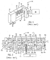
FIG. 1 (prior art) is a simplified perspective view, in partial phantom, of a distributed modular I/O system having an adapter communicating on a backplane to one or more detachable I/O modules; -
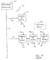
FIG. 2 (prior art) is a block diagram of the distributed I/O system ofFIG. 1 showing the interconnection of the adapter to the I/O modules via backplane data conductors and slot address signals; -
FIG. 3 (prior art) is simplified diagrammatic illustration showing a distributed block I/O module and also the distributed modular I/O system ofFIG. 1 as part of an overall industrial automation control system; -
FIG. 4 shows the block I/O module and the modular I/O system ofFIGS 1-3 replaced with intelligent self-determining I/O devices in accordance with the present development; -
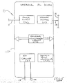
FIG. 5 is a diagrammatic illustration of a single intelligent self-determining I/O device formed in accordance with the present development; -
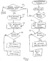
FIG. 6 is a flow chart that discloses an initialization process for an intelligent self-determining I/O device formed in accordance with the present development. - Referring now to
FIG. 1 , an I/O system 10 for use with an industrial controller includes a network adapter ornetwork adapter module 12 providing aconnection 14 to a high-speed,serial network 16. Thenetwork 16 may be any one of a number of high-speed serial networks including ControlNet, EtherNet or the like. Theadapter module 12 communicates over thenetwork 16 with an industrial controller (not shown) to receive output data from the industrial controller or to provide input data to the industrial controller to be processed according to a control program. - The
adapter module 12 communicates with abackplane 18 to connect it to one or more I/O modules 20. The I/O modules 20 connect via I/O lines (e.g., electrical cables, fiber optic cables, etc.) 24 with a controlledprocess 26. As is understood in the art, the I/O modules 20 convert digital data received over thebackplane 18 from theadapter module 12 into output signals (either digital or analog) in a form suitable for connection to theindustrial process 26. The I/O modules 20 typically also receive digital or analog signals from theindustrial process 26 and convert it to digital data suitable for transmission on thebackplane 18 to theadapter module 12. - Modularity of the I/
O system 10 is provided through a rear extendingconnector 28 on each I/O module 20 which may be mated with any one of a number ofconnectors 30 extending from the front surface of thebackplane 18. Theconnectors 30 are each associated with "slots" providing mechanical features (not shown) for otherwise securing the I/O module 20. - In the shown parallel bus embodiment,
connectors 30 receive paralleldata bus conductors 32, over which data may be read and written, andslot address signals 34 which are enabled one at a time to indicate the slot and hence the I/O module 20 for which the data ofdata bus conductors 32 is intended or from which data is being solicited. Thedata bus conductors 32 also include control lines including a clock and read/write line indicating timing for a data transfer according to techniques well known in the art. - In an alternative serial bus embodiment, not shown, slot address signals are attached to the data blocks sent over a serial data bus connector or are implicit in the ordering or timing of the data blocks being sent. While the invention is applicable to both serial and parallel bus embodiments, only the former will be discussed in detail from which description the latter will be apparent to those of ordinary skill in the art.
- Referring now to
FIG. 2 , theadapter module 12 includes anetwork interface 35 communicating with theconnector 14 to decode and encode data exchanged with thenetwork 16. Thenetwork interface 35 in turn communicates with aninternal bus 36 which connects thenetwork interface 35 to aprocessor 38 and amemory 40. Thememory 40 includes a buffer 42 (divided into input and output sections) and anoperating program 44 allowing theprocessor 38 to operate on the data passing on theinternal bus 36 according to the methods of the present invention as will be described. Theadapter module 12 also includes a power supply PS. - The
internal bus 36 also connects tobackplane data interface 46 andbackplane address decoder 48. I/O modules 20a-20c, when connected to thebackplane 18, communicate with thedata bus conductors 32 andslot address signals 34 via abackplane interface 50a-50c, respectively. Each I/O module 20a-20c comprises I/O circuitry C that: (i) connects via I/O lines 24 with a controlledprocess 26; (ii) converts digital data received over thebackplane 18 from theadapter module 12 into output signals (either digital or analog) in a form suitable for connection to theindustrial process 26; and/or, (iii) receives digital or analog signals from theindustrial process 26 and converts it to digital data suitable for transmission on thebackplane 18 to theadapter module 12. - More particularly, in each I/
O module 20a-20c, backplane interface 50 (each component denoted a-c to reflect the particular I/O module) in turn communicates with an internal bus 52 (i.e., 52a, 52b, etc.), which communicates with aninternal processor 54 andmemory 56, the latter which includes a buffer portion 58 and an operating program 60. The internal bus 52 also communicates with I/O circuitry 62 providing level shifting, conversion and filtering necessary for the interface to the controlled process. The backplane interface 50 andaddress decoders - As is generally known in the art, the
network adapter 12 and at least one of the I/O modules 20a-20c can be integrated into a single enclosure to define a "block" I/O device 10b as shown inFIG. 3. FIG. 3 illustrates the block I/O device 10b and also the modular I/O system 10 ofFIGS. 1 and 2 as part of an industrial automation control system S. More particularly, anindustrial controller 100 comprising a scanner is connected to thedata network 16. The block I/O device 10b and modular I/O system 10 are connected to thenetwork 16 viarespective network adapters 12 and are located remotely from thecontroller 100. As noted above, the modular I/O system 10 comprises multiple I/O modules 20a-20d. The I/O circuits C of thedevices 10,10b connect via I/O lines 24 with one or more controlledprocesses 26. The I/O circuits C convert digital data received fromcontroller 100 vianetwork adapter 12 into output signals (either digital or analog) for input to theindustrial process 26. Likewise, the I/O circuits C receive digital or analog signals from theindustrial process 26 and convert same to digital data suitable for input tocontroller 100 vianetwork adapter 12. - A known industrial control system S, such as that illustrated in
FIG. 3 , can be thought of as comprising three potential types of I/O devices: a block I/O device 10b; anetwork adapter module 12 of a modular I/O device 10; or, an I/O module 20 of a modular I/O device 10. Also, the I/O modules 20 can be further sub-classified as: a terminal I/O module; or an intermediate I/O module. A "terminal" I/O module is the final or most downstream module (20d in the illustrated example) in a series of modules operably connected to thenetwork adapter module 12; an "intermediate" I/O module is anymodule 20a-20c located between thenetwork adapter module 12 and the terminal module of the modular I/O device 10. Those of ordinary skill in the art will recognize that the modular I/O system 10 can comprise only thenetwork adapter module 12 and a single I/O module 20, in which case the single I/O module 20 would be deemed the terminal I/O module. - As shown in
FIG. 4 , in accordance with the present development, it has been deemed desirable to provide multiple units of a single type of universal distributed I/O device D (labeled as D1,D2,D3a,D3b but shown generally at D inFIG. 5 ) that can function as any one of the above I/O devices: (1) as a block I/O device D1; (2) as a network adapter module D2; (3) as an end I/O module D3a; or, (4) as an intermediate I/O module D3b. Furthermore, the device D is intelligent and self-determining in that it performs an initialization process by which it determines its role according to its operative location in an industrial control system S'. - With reference now to
FIG. 5 , each I/O device D comprises a housing orenclosure 120 that is sealed to prevent ingress of environmental contamination such as water, air, dirt, etc. In one example, thehousing 120 meets standards such as IP67 NEMA 4X / 6P and the like. The device D must be able to function as a conventional block I/O device and, thus, thehousing 120 contains all components of a block I/O device such as the device 10b described above, i.e., a power supply PS, anetwork adapter 12, at least one I/O circuit C. The I/O circuit C communicates with a process 26 (not shown inFIG. 5 ) via I/O lines 24 that connect to the I/O circuit via conventional plug type connectors or the like. The power supply PS is connected to a voltage input line V. Thenetwork adapter 12 is connected todata network 16 viaconnection 14. - Unlike a conventional block I/O device 10b, the device D further comprises a device setup controller 130 and a
backplane communication circuit 132. The device setup controller 130 is provided as any suitable electronic controller device such as a programmed general purpose microcontroller or another device such as a dedicated electronic circuit, e.g., an ASIC, and is configured to control operation of the device D and, in particular, an initialization process (FIG. 6 ) by which the device D performs a self-determination routine in order to identify its intended use based upon its operative installed location in an industrial automation system S'. - The
backplane communication circuit 132 is provided as any suitable wired or wireless communication circuit by which the device D is able to transmit I/O and associated data upstream (i.e., toward the industrial controller 100) or downstream (i.e., away from the industrial controller 100) to another device D and/or to thecontroller 100 vianetwork 16 as disclosed above in connection with thebackplane 18 of modular I/O device 10. Upstream and downstream devices D are connected to each other by way of thebackplane communication circuit 132 using electrical and/or fiber optic cables and/or wireless protocols to construct a data backplane 118 (FIG. 4 ) by which the upstream and downstream devices D send and receive I/O data to/from each other and, ultimately, to/from theindustrial controller 100. It should be noted that if a wireless protocol is implemented by thebackplane communication circuit 132, it should be short-range and/or line-of-sight or otherwise configured to ensure that a plurality of the devices D that form part of a control system S' do not receive extraneous backplane data signals, i.e., each device D must be able to determine its location relative to any other devices D as described below and extraneous backplane data signals could be undesirable to this process. Examples of suitable communications circuits to be implemented by thebackplane communication circuit 132 include hard-wired circuits and/or wireless circuits. -
FIG. 6 illustrates the initialization process implemented by the device setup controller 130 upon power-up of each universal I/O device D installed in the control system S'. In a step S1, the setup controller 130 determines if the device D is receiving network data into thenetwork adapter 12. If yes, the setup controller 130 implements a step S2 to send backplane test data downstream viabackplane communication circuit 132. A step S3 is then implemented by the setup controller 130 to determine if a response/acknowledgement to the data sent in step S2 is received viabackplane communication circuit 132. If not, the setup controller 130 sets the configuration of the device D as a stand-alone block I/O device as shown at D1 inFIG. 4 . If the setup controller 130 determines via step S3 that a response is received to the data sent in step S2, the controller sets the configuration of the device D as an I/O network adapter module as shown at D2 inFIG. 4 . - If the setup controller determines through the step S1 that no network data are being received into the
network adapter 12, control passes to a step S4 wherein the setup controller 130 checks to see if upstream backplane test data (i.e., data from upstream) are being received viabackplane communication circuit 132. If not, the setup controller 130 determines that an error condition is present because the device D is not receiving any network data and is not receiving any upstream backplane test data. If the step S4 indicates that upstream backplane test data are being received viabackplane communication circuit 132, the setup controller 130 carries out a step S5 to send a response upstream (i.e., an acknowledgement signal) on thebackplane communication circuit 132 to the device D from which the upstream backplane test data are being received. - Before or after or concurrently with step S5, the setup controller 130 implements a step S6 to send backplane test data downstream via
backplane communication circuit 132. In a step S7, the setup controller 130 checks to see if any acknowledgement response is received on thebackplane communication circuit 132 to the data sent downstream in step S6. If a response is received according to step S7, the setup controller 130 configures the device D as an intermediate I/O module as shown at D3b inFIG. 4 ; if no response is received according to the step S7, the setup controller 130 configures the device D as a terminal I/O module as shown at D3a inFIG. 4 . - It should be noted that each device D used in an industrial control system S' can have a different I/O circuit C relative to the other devices used in the system S'. The I/O circuit C of each device is configured with the needed input/output connectors for mating with I/
O lines 24 and other capabilities (e.g., digital, analog, etc.) as needed. - Modifications and alterations will occur to those of ordinary skill in the art. It is intended that the following claims be construed literally and/or according to the doctrine of equivalents so as to encompass all such modifications and alterations to the fullest extent available under the law.
- In summary the invention discloses a universal input/output device for an industrial automation control system including a housing, a power supply for connecting to a voltage source, an input/output circuit for communicating with an industrial process, and a network adapter circuit for communicating data to and from a data network. The device also includes a backplane communication circuit for sending backplane data upstream and downstream along a backplane, and a device setup control circuit. The device setup control circuit performs an initialization process to configure said device as one of: (i) a stand-along block I/O device; (ii) a network adapter module of a modular I/O device; or (iii) an I/O module of a modular I/O device. The configuration method is automatic and based upon data being received into the device.
Claims (5)
- An universal input/output device (D, D1, D2) for an industrial automation control system, said device comprising:- a housing (120);- a power supply (PS) for connecting to a voltage source;- an input/output circuit (C) for communicating with an industrial process;- a network adapter circuit (12) for communicating data to and from a data network (16);- a backplane communication circuit (132) for sending backplane data upstream and downstream along a backplane; and,- a device setup control circuit (130) that performs an initialization process to configure said device (D, D1, D2) as one of:characterized in that(i) a stand-along block I/O device;(ii) a network adapter module of a modular I/O device; or(iii) an I/O module of a modular I/O device
said device setup control circuit (130) comprises means for sending and receiving backplane test data to adjacent devices (D, D1, D2) via said backplane communication circuit (132), and wherein said setup control circuit (130) configures said device (D, D1, D2) based upon receipt of an acknowledgement response from an adjacent device via said backplane communication circuit (132). - The universal input/output device as set forth in claim 1, wherein said device setup control circuit (130) further configures said device (D, D1, D2) as one of:(i) a terminal I/O module; or,(ii) a intermediate I/O module.
- The universal input/output device as set forth in claim 1, wherein said backplane communication circuit (132) comprises a wireless communication circuit for sending and receiving wireless backplane data to upstream and downstream devices.
- An industrial automation control system, said system comprising at least two intelligent self-determining I/O devices (D, D1, D2), each of said I/O devices (D, D1, D2) comprising:- a housing (120);- a power supply (PS) for connecting to a voltage source;- an input/output circuit (C) for communicating with an industrial process;- a network adapter circuit (12) for communicating data to and from a data network (16);- a backplane communication circuit (132) for sending backplane data upstream and downstream along a backplane; and,- a device setup control circuit (130) that performs an initialization process to configure said device (D, D1, D2) as one of:characterized in that(i) a stand-along block I/O device;(ii) a network adapter module of a modular I/O device; or(iii) an I/O module of a modular I/O device
said device setup control circuit (130) comprises means for sending and receiving backplane test data to adjacent devices (D, D1, D2) via said backplane communication circuit (132), and wherein said setup control circuit (130) configures said device (D, D1, D2) based upon receipt of an acknowledgement response from an adjacent device via said backplane communication circuit (132). - A method for constructing an industrial automation control system, said method comprising:- connecting a plurality of intelligent self-determining I/O devices to a data network (16);- performing an initialization routine with each of said intelligent self-determining I/O devices (D, D1, D2),characterized in that
said initialization routine comprising for each of said intelligent self-determining I/O device (D, D1, D2):(a) determining (S1) if network data are being received into said device (D, D1, D2);(b) determining (S4) if upstream backplane test data are being received into said device (D, D1, D2);(c) determining (S3; S7) if downstream backplane test data are being received into said device (D, D1, D2); and,(d) configuring said device (D, D1, D2) as one of(i) a stand-along block I/O device;(ii) a network adapter module of a modular I/O device; or(iii) an I/O module of a modular I/O device based upon whether at least one of network data, upstream backplane test data, and downstream backplane test data are received into said device.
Applications Claiming Priority (2)
| Application Number | Priority Date | Filing Date | Title |
|---|---|---|---|
| US10/793,236 US7412548B2 (en) | 2004-03-04 | 2004-03-04 | Intelligent self-determining I/O device |
| US793236 | 2004-03-04 |
Publications (3)
| Publication Number | Publication Date |
|---|---|
| EP1571510A2 EP1571510A2 (en) | 2005-09-07 |
| EP1571510A3 EP1571510A3 (en) | 2006-11-22 |
| EP1571510B1 true EP1571510B1 (en) | 2008-11-05 |
Family
ID=34750624
Family Applications (1)
| Application Number | Title | Priority Date | Filing Date |
|---|---|---|---|
| EP05004721A Active EP1571510B1 (en) | 2004-03-04 | 2005-03-03 | Intelligent self-determining I/O device |
Country Status (3)
| Country | Link |
|---|---|
| US (1) | US7412548B2 (en) |
| EP (1) | EP1571510B1 (en) |
| DE (1) | DE602005010766D1 (en) |
Families Citing this family (52)
| Publication number | Priority date | Publication date | Assignee | Title |
|---|---|---|---|---|
| US9565275B2 (en) * | 2012-02-09 | 2017-02-07 | Rockwell Automation Technologies, Inc. | Transformation of industrial data into useful cloud information |
| US7711440B1 (en) | 2006-09-28 | 2010-05-04 | Rockwell Automation Technologies, Inc. | Browser based embedded historian |
| US7672740B1 (en) | 2006-09-28 | 2010-03-02 | Rockwell Automation Technologies, Inc. | Conditional download of data from embedded historians |
| US7742833B1 (en) | 2006-09-28 | 2010-06-22 | Rockwell Automation Technologies, Inc. | Auto discovery of embedded historians in network |
| US8181157B2 (en) * | 2006-09-29 | 2012-05-15 | Rockwell Automation Technologies, Inc. | Custom language support for project documentation and editing |
| US7913228B2 (en) * | 2006-09-29 | 2011-03-22 | Rockwell Automation Technologies, Inc. | Translation viewer for project documentation and editing |
| US7933666B2 (en) * | 2006-11-10 | 2011-04-26 | Rockwell Automation Technologies, Inc. | Adjustable data collection rate for embedded historians |
| US7974937B2 (en) * | 2007-05-17 | 2011-07-05 | Rockwell Automation Technologies, Inc. | Adaptive embedded historians with aggregator component |
| WO2009002464A2 (en) * | 2007-06-22 | 2008-12-31 | Vubiq Incorporated | System and method for wireless communication in a backplane fabric architecture |
| US7768457B2 (en) * | 2007-06-22 | 2010-08-03 | Vubiq, Inc. | Integrated antenna and chip package and method of manufacturing thereof |
| US7930639B2 (en) * | 2007-09-26 | 2011-04-19 | Rockwell Automation Technologies, Inc. | Contextualization for historians in industrial systems |
| US7917857B2 (en) * | 2007-09-26 | 2011-03-29 | Rockwell Automation Technologies, Inc. | Direct subscription to intelligent I/O module |
| US7930261B2 (en) | 2007-09-26 | 2011-04-19 | Rockwell Automation Technologies, Inc. | Historians embedded in industrial units |
| US7882218B2 (en) * | 2007-09-27 | 2011-02-01 | Rockwell Automation Technologies, Inc. | Platform independent historian |
| US7962440B2 (en) | 2007-09-27 | 2011-06-14 | Rockwell Automation Technologies, Inc. | Adaptive industrial systems via embedded historian data |
| US7809656B2 (en) | 2007-09-27 | 2010-10-05 | Rockwell Automation Technologies, Inc. | Microhistorians as proxies for data transfer |
| US20090089671A1 (en) * | 2007-09-28 | 2009-04-02 | Rockwell Automation Technologies, Inc. | Programmable controller programming with embedded macro capability |
| GB0903836D0 (en) | 2009-03-05 | 2009-04-22 | Oxford Instr Plasma Technology | Interface module and controller network |
| US20100268850A1 (en) * | 2009-04-17 | 2010-10-21 | Burton Lambert J | Modular I/O System With Automated Commissioning |
| US8019839B2 (en) | 2009-05-11 | 2011-09-13 | Accenture Global Services Limited | Enhanced network adapter framework |
| US9188440B2 (en) * | 2009-07-02 | 2015-11-17 | Carlson Software, Inc. | High precision hand-held engineering survey/position data collector tablet computer |
| US20110000095A1 (en) * | 2009-07-02 | 2011-01-06 | Robert Bruce Carlson | High Precision Hand-held Engineering Survey/Position Data Collector |
| US9477936B2 (en) | 2012-02-09 | 2016-10-25 | Rockwell Automation Technologies, Inc. | Cloud-based operator interface for industrial automation |
| EP2793091A1 (en) * | 2013-04-16 | 2014-10-22 | Alstom Technology Ltd | Distributed control system |
| TWI495969B (en) * | 2013-05-08 | 2015-08-11 | Pegatron Corp | Method for automatically determining the sequence of multiple machines |
| US9703902B2 (en) | 2013-05-09 | 2017-07-11 | Rockwell Automation Technologies, Inc. | Using cloud-based data for industrial simulation |
| US9709978B2 (en) | 2013-05-09 | 2017-07-18 | Rockwell Automation Technologies, Inc. | Using cloud-based data for virtualization of an industrial automation environment with information overlays |
| US9989958B2 (en) | 2013-05-09 | 2018-06-05 | Rockwell Automation Technologies, Inc. | Using cloud-based data for virtualization of an industrial automation environment |
| US9786197B2 (en) | 2013-05-09 | 2017-10-10 | Rockwell Automation Technologies, Inc. | Using cloud-based data to facilitate enhancing performance in connection with an industrial automation system |
| US10026049B2 (en) | 2013-05-09 | 2018-07-17 | Rockwell Automation Technologies, Inc. | Risk assessment for industrial systems using big data |
| US9438648B2 (en) | 2013-05-09 | 2016-09-06 | Rockwell Automation Technologies, Inc. | Industrial data analytics in a cloud platform |
| US9508267B2 (en) | 2013-06-09 | 2016-11-29 | Cae Inc. | Configurable simulator with testing capabilities |
| DE102014012660A1 (en) * | 2013-12-11 | 2015-06-11 | Diehl Aerospace Gmbh | Configurable interface circuit |
| WO2015143533A1 (en) * | 2014-03-26 | 2015-10-01 | Cae Inc. | Configurable input/output unit |
| US10114783B2 (en) | 2014-03-26 | 2018-10-30 | Cae Inc. | Configurable input/output unit |
| US8843660B1 (en) * | 2014-03-26 | 2014-09-23 | Cae Inc. | Configurable simulator for performing a distributed simulation |
| US8868808B1 (en) * | 2014-03-26 | 2014-10-21 | Cae Inc. | Configurable simulator with a plurality of configurable modular cards |
| CN107079064B (en) * | 2014-06-04 | 2021-08-27 | 莫都威尔私人有限公司 | Device for storing and routing electrical power and data to at least one party |
| US9894119B2 (en) | 2014-08-29 | 2018-02-13 | Box, Inc. | Configurable metadata-based automation and content classification architecture for cloud-based collaboration platforms |
| US11243505B2 (en) | 2015-03-16 | 2022-02-08 | Rockwell Automation Technologies, Inc. | Cloud-based analytics for industrial automation |
| US11042131B2 (en) | 2015-03-16 | 2021-06-22 | Rockwell Automation Technologies, Inc. | Backup of an industrial automation plant in the cloud |
| US11513477B2 (en) | 2015-03-16 | 2022-11-29 | Rockwell Automation Technologies, Inc. | Cloud-based industrial controller |
| US10496061B2 (en) | 2015-03-16 | 2019-12-03 | Rockwell Automation Technologies, Inc. | Modeling of an industrial automation environment in the cloud |
| US9940285B2 (en) * | 2015-11-20 | 2018-04-10 | General Electric Company | Configurable IO-channel system with embedded microcontroller |
| US10248609B2 (en) | 2016-01-06 | 2019-04-02 | Verifone, Inc. | Modular interconnection system and components therefor |
| US10310837B2 (en) | 2016-08-25 | 2019-06-04 | General Electric Company | Method and apparatus for updating industrial assets |
| US10503668B2 (en) | 2016-10-18 | 2019-12-10 | Honeywell International Inc. | Intelligent field input/output (I/O) terminal for industrial control and related system and method |
| US9861002B1 (en) | 2016-10-20 | 2018-01-02 | Rockwell Automation Technologies, Inc. | Single channel I/O in a modular sub-chassis |
| US10261486B2 (en) | 2016-10-20 | 2019-04-16 | Rockwell Automation Technologies, Inc. | On machine input/output (I/O) system with modular connections |
| US10579027B2 (en) | 2017-05-24 | 2020-03-03 | Honeywell International Inc. | Redundant universal IO modules with integrated galvanically isolated (GI) and intrinsically safe (IS) barriers |
| US11300604B2 (en) * | 2018-04-06 | 2022-04-12 | Bently Nevada, Llc | Monitoring system with serial data lane transmission network |
| EP3799548A1 (en) * | 2019-09-09 | 2021-03-31 | Baker Hughes Oilfield Operations LLC | Instrument panel for monitoring system |
Family Cites Families (12)
| Publication number | Priority date | Publication date | Assignee | Title |
|---|---|---|---|---|
| DE3534465A1 (en) | 1985-09-27 | 1987-04-09 | Kloeckner Moeller Elektrizit | Distributed system of stored program controllers |
| EP0620510A1 (en) | 1993-04-15 | 1994-10-19 | Siemens Aktiengesellschaft | Electrical apparatus with a configurable interface |
| US6175770B1 (en) | 1997-12-31 | 2001-01-16 | Dana Corporation | Electronic controller having automatic self-configuration capabilities |
| US6175932B1 (en) * | 1998-04-20 | 2001-01-16 | National Instruments Corporation | System and method for providing state capture and restoration to an I/O system |
| US6286060B1 (en) * | 1998-06-26 | 2001-09-04 | Sun Microsystems, Inc. | Method and apparatus for providing modular I/O expansion of computing devices |
| US7734852B1 (en) * | 1998-08-06 | 2010-06-08 | Ahern Frank W | Modular computer system |
| US6308231B1 (en) | 1998-09-29 | 2001-10-23 | Rockwell Automation Technologies, Inc. | Industrial control systems having input/output circuits with programmable input/output characteristics |
| US6484215B1 (en) | 1998-11-16 | 2002-11-19 | Rockwell Technologies, Llc | System having I/O module number assignment utilizing module number signal line having pair of inputs adapted for receiving module number signal and propagation of module number signal down stream |
| US6697892B1 (en) * | 1999-07-08 | 2004-02-24 | Intel Corporation | Port expansion system |
| US6662247B1 (en) | 1999-11-30 | 2003-12-09 | Rockwell Automation Technologies, Inc. | Protocol for extended data transfer in scan-based industrial controller I/O system |
| US6909923B2 (en) * | 1999-12-22 | 2005-06-21 | Rockwell Automation Technologies, Inc. | Safety communication on a single backplane |
| TW578043B (en) * | 2001-06-18 | 2004-03-01 | Oqo Inc | Modular computing system |
-
2004
- 2004-03-04 US US10/793,236 patent/US7412548B2/en active Active
-
2005
- 2005-03-03 DE DE602005010766T patent/DE602005010766D1/en active Active
- 2005-03-03 EP EP05004721A patent/EP1571510B1/en active Active
Also Published As
| Publication number | Publication date |
|---|---|
| EP1571510A3 (en) | 2006-11-22 |
| EP1571510A2 (en) | 2005-09-07 |
| US7412548B2 (en) | 2008-08-12 |
| US20050198406A1 (en) | 2005-09-08 |
| DE602005010766D1 (en) | 2008-12-18 |
Similar Documents
| Publication | Publication Date | Title |
|---|---|---|
| EP1571510B1 (en) | Intelligent self-determining I/O device | |
| US7581053B2 (en) | Distributed modular input/output system with wireless backplane extender | |
| EP3715976B1 (en) | Modular backplane for an industrial controller | |
| US9966714B1 (en) | I/O migration adapter for control system | |
| US7596635B2 (en) | Method and apparatus for providing redundant I/O adapters in machine and process controllers | |
| EP3798770B1 (en) | Removable terminal block assembly that permits an i/o base to operate in simplex mode or duplex mode | |
| US7656846B2 (en) | PLC based wireless communications | |
| US20210144877A1 (en) | Modular interface system for connecting a control device and field devices | |
| EP2899640B1 (en) | Servo drive device | |
| US9861002B1 (en) | Single channel I/O in a modular sub-chassis | |
| EP3312687B1 (en) | On machine input/output (i/o) system with modular connections | |
| US20190391548A1 (en) | Front adapter for connecting to a control device and automation system | |
| WO2021092257A1 (en) | Input/output apparatus and methods for monitoring and/or controlling dynamic environments | |
| US10963412B2 (en) | Flexible expandable automation device with hot-swappable I/O-units | |
| CN110663226B (en) | Data bus user device | |
| US11269800B2 (en) | Integrated communication unit | |
| KR100894861B1 (en) | Modularized motion controller based on distributed network | |
| JP5670780B2 (en) | Electro-optic coupling device | |
| CN109698779B (en) | Communication participant and communication system | |
| CN117083573A (en) | Automation system and method for operating an automation system | |
| JPH10333720A (en) | Programmable logic controller | |
| CN117472829A (en) | Information processing apparatus | |
| CN116997869A (en) | Main unit and communication system | |
| JPS6214554A (en) | Line switching device |
Legal Events
| Date | Code | Title | Description |
|---|---|---|---|
| PUAI | Public reference made under article 153(3) epc to a published international application that has entered the european phase |
Free format text: ORIGINAL CODE: 0009012 |
|
| AK | Designated contracting states |
Kind code of ref document: A2 Designated state(s): AT BE BG CH CY CZ DE DK EE ES FI FR GB GR HU IE IS IT LI LT LU MC NL PL PT RO SE SI SK TR |
|
| AX | Request for extension of the european patent |
Extension state: AL BA HR LV MK YU |
|
| PUAL | Search report despatched |
Free format text: ORIGINAL CODE: 0009013 |
|
| AK | Designated contracting states |
Kind code of ref document: A3 Designated state(s): AT BE BG CH CY CZ DE DK EE ES FI FR GB GR HU IE IS IT LI LT LU MC NL PL PT RO SE SI SK TR |
|
| AX | Request for extension of the european patent |
Extension state: AL BA HR LV MK YU |
|
| RIC1 | Information provided on ipc code assigned before grant |
Ipc: G05B 19/05 20060101AFI20061019BHEP |
|
| 17P | Request for examination filed |
Effective date: 20070131 |
|
| AKX | Designation fees paid |
Designated state(s): DE FR GB IT |
|
| 17Q | First examination report despatched |
Effective date: 20071102 |
|
| GRAP | Despatch of communication of intention to grant a patent |
Free format text: ORIGINAL CODE: EPIDOSNIGR1 |
|
| GRAS | Grant fee paid |
Free format text: ORIGINAL CODE: EPIDOSNIGR3 |
|
| GRAA | (expected) grant |
Free format text: ORIGINAL CODE: 0009210 |
|
| AK | Designated contracting states |
Kind code of ref document: B1 Designated state(s): DE FR GB IT |
|
| REG | Reference to a national code |
Ref country code: GB Ref legal event code: FG4D |
|
| REF | Corresponds to: |
Ref document number: 602005010766 Country of ref document: DE Date of ref document: 20081218 Kind code of ref document: P |
|
| PLBE | No opposition filed within time limit |
Free format text: ORIGINAL CODE: 0009261 |
|
| STAA | Information on the status of an ep patent application or granted ep patent |
Free format text: STATUS: NO OPPOSITION FILED WITHIN TIME LIMIT |
|
| 26N | No opposition filed |
Effective date: 20090806 |
|
| REG | Reference to a national code |
Ref country code: FR Ref legal event code: PLFP Year of fee payment: 12 |
|
| REG | Reference to a national code |
Ref country code: FR Ref legal event code: PLFP Year of fee payment: 13 |
|
| REG | Reference to a national code |
Ref country code: FR Ref legal event code: PLFP Year of fee payment: 14 |
|
| PGFP | Annual fee paid to national office [announced via postgrant information from national office to epo] |
Ref country code: FR Payment date: 20230222 Year of fee payment: 19 |
|
| PGFP | Annual fee paid to national office [announced via postgrant information from national office to epo] |
Ref country code: IT Payment date: 20230221 Year of fee payment: 19 Ref country code: GB Payment date: 20230221 Year of fee payment: 19 Ref country code: DE Payment date: 20230221 Year of fee payment: 19 |
|
| P01 | Opt-out of the competence of the unified patent court (upc) registered |
Effective date: 20230404 |