EP1574763A1 - Valve with sealed shaft and the method of mounting the valve - Google Patents
Valve with sealed shaft and the method of mounting the valve Download PDFInfo
- Publication number
- EP1574763A1 EP1574763A1 EP05290438A EP05290438A EP1574763A1 EP 1574763 A1 EP1574763 A1 EP 1574763A1 EP 05290438 A EP05290438 A EP 05290438A EP 05290438 A EP05290438 A EP 05290438A EP 1574763 A1 EP1574763 A1 EP 1574763A1
- Authority
- EP
- European Patent Office
- Prior art keywords
- sleeve
- shutter
- shaft
- hub
- bore
- Prior art date
- Legal status (The legal status is an assumption and is not a legal conclusion. Google has not performed a legal analysis and makes no representation as to the accuracy of the status listed.)
- Granted
Links
Images


Classifications
-
- F—MECHANICAL ENGINEERING; LIGHTING; HEATING; WEAPONS; BLASTING
- F16—ENGINEERING ELEMENTS AND UNITS; GENERAL MEASURES FOR PRODUCING AND MAINTAINING EFFECTIVE FUNCTIONING OF MACHINES OR INSTALLATIONS; THERMAL INSULATION IN GENERAL
- F16K—VALVES; TAPS; COCKS; ACTUATING-FLOATS; DEVICES FOR VENTING OR AERATING
- F16K41/00—Spindle sealings
- F16K41/02—Spindle sealings with stuffing-box ; Sealing rings
- F16K41/04—Spindle sealings with stuffing-box ; Sealing rings with at least one ring of rubber or like material between spindle and housing
- F16K41/043—Spindle sealings with stuffing-box ; Sealing rings with at least one ring of rubber or like material between spindle and housing for spindles which only rotate, i.e. non-rising spindles
- F16K41/046—Spindle sealings with stuffing-box ; Sealing rings with at least one ring of rubber or like material between spindle and housing for spindles which only rotate, i.e. non-rising spindles for rotating valves
-
- F—MECHANICAL ENGINEERING; LIGHTING; HEATING; WEAPONS; BLASTING
- F16—ENGINEERING ELEMENTS AND UNITS; GENERAL MEASURES FOR PRODUCING AND MAINTAINING EFFECTIVE FUNCTIONING OF MACHINES OR INSTALLATIONS; THERMAL INSULATION IN GENERAL
- F16K—VALVES; TAPS; COCKS; ACTUATING-FLOATS; DEVICES FOR VENTING OR AERATING
- F16K1/00—Lift valves or globe valves, i.e. cut-off apparatus with closure members having at least a component of their opening and closing motion perpendicular to the closing faces
- F16K1/16—Lift valves or globe valves, i.e. cut-off apparatus with closure members having at least a component of their opening and closing motion perpendicular to the closing faces with pivoted closure-members
- F16K1/18—Lift valves or globe valves, i.e. cut-off apparatus with closure members having at least a component of their opening and closing motion perpendicular to the closing faces with pivoted closure-members with pivoted discs or flaps
- F16K1/22—Lift valves or globe valves, i.e. cut-off apparatus with closure members having at least a component of their opening and closing motion perpendicular to the closing faces with pivoted closure-members with pivoted discs or flaps with axis of rotation crossing the valve member, e.g. butterfly valves
- F16K1/226—Shaping or arrangements of the sealing
- F16K1/2268—Sealing means for the axis of rotation
Definitions
- the present invention relates to shut-off valves offset.
- an offset shutter valve the axis of rotation of the shutter disk-shaped is offset from the plane of the shutter and is parallel to this plane.
- the axis of rotation is also eccentric with respect to the axis of piping.
- the combination of offset and eccentricity reduces the friction between the seat (seal) and the sealing surface when opening and closing the faucet.
- the faucet thus retains its characteristics after a very large number of maneuvers, these characteristics remaining compliant with standards and specifications, the most demanding. It is why, we use a lot of offset butterfly valves in the field high pressure, as well as in the field of water (adduction).
- the shutter is rotated about a quarter of a turn by a which further ensures the function of supporting the shutter when the latter is closed.
- a axis that plays a role identical to that of the tree as a support for the shutter, but which is not leading.
- the word "tree” also includes the axis opposite to the tree itself.
- a serious disadvantage of these offset shutter valves is that the shaft is exposed to the liquid that passes through the tap, especially as the liquid is under high pressure.
- the treatment of water consists in treating discharges by mechanical filtration and cation rebalancing and, where appropriate, optionally, addition of basic or acidic additives. It can also be done in the supply of drinking water that pumping carried out not far from the edge of the sea bring in the channels of slightly salty water aggressive vis-à-vis metals.
- operators inject oxidants into the water in the form of ozone and / or bleach.
- the drinking water thus contains oxidants which, especially in countries where the temperature can reach 60 ° C under shelter, have a high activity and are the source of pitting corrosion on ferrous metals.
- the body and the shutter of the faucets can be coated with ebonite or thick paint but trees and bores correspondents are not protected, so that the specifications specify that the material of the shaft in contact with the fluid must meet a minimum value determined by a quantity called "puncture index". This puncture index depends on the percentage of chromium, the percentage of molybdenum and that of nitrogen contained in the material. To satisfy this condition, the choice of material for trees is reduced to steels austenitic stainless and austenitic-ferritic stainless steels still called duplexes.
- the former have weak mechanical characteristics and the average mechanical characteristics, if we compare them with those of martensitic or precipitation stainless steels, these two shades being widely used in butterfly-centered faucets where there is no contact between shaft / axis and product conveyed.
- the invention radically suppresses corrosion of the tree by sting.
- the invention therefore relates to a faucet comprising a body cylindrical tubular whose opening can be closed by a shutter in disc form integral in rotation with a shaft, extending in a manner offset from the plane of the shutter and parallel to this plane, by via a hub in one piece with the shutter, characterized in that what the outer surface of the section of the tree, extending between the body and the hub, is provided with a means of protection vis-à-vis the corrosion and it is provided a first seal between the body and the means of protection and a second seal between the shutter and the means of protection.
- the protective means is a sleeve surrounding a large part of the tree, that is to say all the part that is at the outside of the hub and which passes through the shaft passage in the body.
- the means of protection is a stretch surrounding the section of the tree, which therefore extends only to the stretch of the tree extending between the body and the hub. The room added to the traditional tap is thus small does not cost much.
- the sleeve comprises a peripheral groove of flexibility that allows him to follow the relative deformations under the effect of the pressure of the parts on which it is centered.
- This throat can also, by the possibility of moving with the help of a tool that it offers, to facilitate fitting the valve making it safer to put the sleeve in place.
- the sleeve may also include a peripheral groove between a first housing for the first upholstery and a second housing for the second garnish.
- the groove is closer to the second housing than the first housing and is intended to receive a elastic ring abutting the radially outermost part of the hub when the sleeve is in position. The elastic ring thus prevents the sleeve to fall back from the position in which it seals.
- the protection means is a surface coating of the section, in particular chromium plating. Way to protection can also be a reported fret on the section.
- the invention it is possible to constitute the stainless steel shaft martensitic and therefore give it a smaller diameter while having a good mechanical resistance, but without fear that it will break under the effect of pitting.
- the method of mounting a valve according to the invention consists to put on a sleeve provided with a first and a second toppings seal and an elastic ring in a bore on the face outside the hub of the shutter so that the elastic ring remains outside the bore on the outer face of the hub, to put the shutter in position in the body by introducing it while the disc is in front until the hole in the hub of the shutter is aligned with the passage tree in the body and to pass the tree in the tree passage and in the bore of the hub.
- this displacement can be performed using a tool engaged in the softening groove which also serves to ensure the final position of the sleeve.
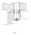
- Figure 1 is a sectional view of an offset butterfly valve according to the invention between two flanges of piping
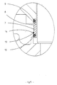
- FIG. 2 is a view on a larger scale of part of the Figure 1 with enlarged view of the part surrounded by an oval, the right part of the figure representing the sleeve before it has reached its final position of mounting and the left part representing the sleeve in final position of mounting.
- Figures 3 and 4 are views similar to that of Figure 2 illustrating variants of the invention.
- Figure 5 shows on a larger scale the part surrounded by a oval of Figure 2.
- the tap shown in FIGS. 1 and 2 is the mode of preferred embodiment of many according to the invention.
- the shut-off valve staggered according to the invention is mounted in Figure 1 between two flanges of a piping.
- the valve essentially comprises a tubular body cylindrical and a disk-shaped shutter 2 mounted rotating relative to a shaft 3 offset from the plane of the shutter and parallel to this plane.
- An actuator 4 allows rotate the shaft 3.
- the shaft 3 is also off-center with respect to the axis of the piping that is to say the body.
- Shutter has one piece with the disc a hub 5 in which is formed a shaft passage.
- the outer surface of the section 3 extending between the body 1 and the hub 5 is provided with a sleeve 7 serving as a means of protection vis-à-vis the corrosion.
- the sleeve 7 of circular cross section is in one material resistant to pitting corrosion such as stainless steel austenitic or austenitic-ferritic stainless. It could also be in one plastic material, such as Teflon, resistant to pressure.
- the sleeve has a peripheral groove 8 decreasing the thickness, so that it can be better deformed under the action of pressure forces and follow a possible decentering of the shaft 3 with respect to the shutter 2.
- the thickness of the Sleeve at the bottom of the groove is 3 mm. In general, this thickness can be between 1 and 5 mm in general.
- Both ends of the sleeve 7 are provided two receiving housings of one first annular seal 9 and a second seal 10 annular sealing.
- the first seal 9 bears with a shoulder 11 of the body 1 and thus prevents the fluid go up along the shaft 3.
- the second seal 10 which as the first is performed in the form of an O-ring comes in contact with a circular bore 12 of the hub 5.
- a peripheral groove 13 in which is housed, when the sleeve 7 is in the mounted state as shown in the part left of Figure 2, an elastic ring 14 which acts as a stop on the face outermost point in the longitudinal direction of the axis of the bore 12. This ring 14 thus retains the sleeve 7.
- the second seal 10 prevents liquid from passing along the shaft 3 between the hub 5 of the shutter and the shaft 3.
- the section of the shaft lying between the body and the hub is surrounded by a ring 15 of corrosion-resistant steel. Both ends of the hoop, respectively applies an annular seal of section U-shaped cross section, one of the branches 16 of the U applying to the fret and the other branch 17 respectively applying to a shoulder 18 of the body and a bore 19 of the hub.
- the embodiment of Figure 4 more expensive but more simple to mount, includes a sleeve 20 extending over the entire passage shaft formed in the body and having two linings 21, 22 sealing respectively cooperating with the body and with the bore of the shutter hub. It is also planned, between the two fittings, a 23 softening throat.
Abstract
Description
La présente invention se rapporte aux robinets à obturateur décalé. Dans un robinet à obturateur décalé, l'axe de rotation de l'obturateur en forme de disque est décalé par rapport au plan de l'obturateur et est parallèle à ce plan. L'axe de rotation est aussi excentré par rapport à l'axe de la tuyauterie. La combinaison du décalage et de l'excentration réduit le frottement entre le siège (joint) et la portée d'étanchéité lors de l'ouverture et de la fermeture du robinet. Le robinet conserve ainsi ses caractéristiques d'étanchéité après un très grand nombre de manoeuvres, ces caractéristiques restant conformes aux normes et spécifications, les plus exigeantes. C'est pourquoi, on utilise beaucoup les robinets à papillon décalé dans le domaine de la haute pression, ainsi que dans le domaine de l'eau (adduction).The present invention relates to shut-off valves offset. In an offset shutter valve, the axis of rotation of the shutter disk-shaped is offset from the plane of the shutter and is parallel to this plane. The axis of rotation is also eccentric with respect to the axis of piping. The combination of offset and eccentricity reduces the friction between the seat (seal) and the sealing surface when opening and closing the faucet. The faucet thus retains its characteristics after a very large number of maneuvers, these characteristics remaining compliant with standards and specifications, the most demanding. It is why, we use a lot of offset butterfly valves in the field high pressure, as well as in the field of water (adduction).
L'obturateur est entraíné en rotation sur un quart de tour par un arbre qui assure en outre la fonctibn de support de l'obturateur quand celui-ci est fermé. A l'opposé de l'arbre se trouve un axe qui joue un rôle identique à celui de l'arbre en tant que support de l'obturateur, mais qui n'est pas menant. Dans le présent mémoire, le mot "arbre" englobe aussi l'axe à l'opposé de l'arbre proprement dit.The shutter is rotated about a quarter of a turn by a which further ensures the function of supporting the shutter when the latter is closed. In contrast to the tree is an axis that plays a role identical to that of the tree as a support for the shutter, but which is not leading. In this specification, the word "tree" also includes the axis opposite to the tree itself.
Un inconvénient grave de ces robinets à obturateur décalé est que l'arbre est exposé au liquide qui passe dans le robinet, d'autant plus que le liquide est sous haute pression. Or, le traitement de l'eau consiste à traiter les rejets par filtration mécanique et par rééquilibrage en cations et, le cas échéant, apport d'additifs basiques ou acides. Il peut aussi se faire dans l'adduction d'eau potable que des pompages effectués non loin du bord de la mer apportent dans les canalisations de l'eau légèrement salée agressive vis-à-vis des métaux. De plus, pour en assurer la compatibilité avec la consommation humaine, les opérateurs injectent dans l'eau des oxydants sous la forme d'ozone et/ou d'eau de javel. L'eau potable contient ainsi des oxydants qui, notamment dans les pays où la température peut atteindre 60° C sous abri, ont une forte activité et sont à l'origine d'une corrosion par piqûre sur les métaux ferreux. Le corps et l'obturateur des robinets peuvent être revêtus d'ébonite ou de peinture épaisse mais les arbres et les alésages correspondants ne sont pas protégés si bien que les cahiers des charges spécifient que le matériau de l'arbre en contact avec le fluide doit satisfaire à une valeur minimum déterminée par une grandeur appelée "indice de piqûre". Cet indice de piqûre dépend du pourcentage de chrome, du pourcentage de molybdène et de celui d'azote contenus dans le matériau. Pour satisfaire à cette condition, le choix du matériau pour les arbres est réduit aux aciers inoxydables austénitiques et aux aciers inoxydables austéno-ferritiques encore appelés duplex.A serious disadvantage of these offset shutter valves is that the shaft is exposed to the liquid that passes through the tap, especially as the liquid is under high pressure. However, the treatment of water consists in treating discharges by mechanical filtration and cation rebalancing and, where appropriate, optionally, addition of basic or acidic additives. It can also be done in the supply of drinking water that pumping carried out not far from the edge of the sea bring in the channels of slightly salty water aggressive vis-à-vis metals. In addition, to ensure compatibility with the human consumption, operators inject oxidants into the water in the form of ozone and / or bleach. The drinking water thus contains oxidants which, especially in countries where the temperature can reach 60 ° C under shelter, have a high activity and are the source of pitting corrosion on ferrous metals. The body and the shutter of the faucets can be coated with ebonite or thick paint but trees and bores correspondents are not protected, so that the specifications specify that the material of the shaft in contact with the fluid must meet a minimum value determined by a quantity called "puncture index". This puncture index depends on the percentage of chromium, the percentage of molybdenum and that of nitrogen contained in the material. To satisfy this condition, the choice of material for trees is reduced to steels austenitic stainless and austenitic-ferritic stainless steels still called duplexes.
Les premiers ont des caractéristiques mécaniques faibles et les seconds des caractéristiques mécaniques moyennes, si on les compare à celles des aciers inoxydables martensitiques ou à précipitation, ces 2 nuances étant largement utilisées dans les robinets à papillon centré où il n'y a pas de contact entre arbre/axe et produit véhiculé.The former have weak mechanical characteristics and the average mechanical characteristics, if we compare them with those of martensitic or precipitation stainless steels, these two shades being widely used in butterfly-centered faucets where there is no contact between shaft / axis and product conveyed.
Le choix d'une nuance austénitique ou austéno-ferritique conduit à un surdimensionnement des arbres, donc à un surcoût par rapport aux solutions concurrentes (martensitiques et aciers à précipitation) qui ne satisfont pas au critère requis pour l'indice de piqûre.The choice of an austenitic or austenitic-ferritic grade leads to over-dimensioning of the trees, therefore to an additional cost compared to competing solutions (martensitic and precipitation steels) which do not meet the required criteria for the puncture index.
L'invention supprime radicalement la corrosion de l'arbre par piqûre.The invention radically suppresses corrosion of the tree by sting.
L'invention a donc pour objet un robinet comprenant un corps tubulaire cylindrique dont l'ouverture peut être obturée par un obturateur en forme de disque solidaire en rotation d'un arbre, s'étendant de manière décalée par rapport au plan de l'obturateur et parallèlement à ce plan, par l'intermédiaire d'un moyeu d'un seul tenant avec l'obturateur, caractérisé en ce que la surface extérieure du tronçon de l'arbre, s'étendant entre le corps et le moyeu, est munie d'un moyen de protection vis-à-vis de la corrosion et il est prévu une première garniture d'étanchéité entre le corps et le moyen de protection et une deuxième garniture d'étanchéité entre l'obturateur et le moyen de protection.The invention therefore relates to a faucet comprising a body cylindrical tubular whose opening can be closed by a shutter in disc form integral in rotation with a shaft, extending in a manner offset from the plane of the shutter and parallel to this plane, by via a hub in one piece with the shutter, characterized in that what the outer surface of the section of the tree, extending between the body and the hub, is provided with a means of protection vis-à-vis the corrosion and it is provided a first seal between the body and the means of protection and a second seal between the shutter and the means of protection.
En prévoyant ainsi un moyen de protection du tronçon de l'arbre et des garnitures d'étanchéité, on empêche le liquide d'arriver au contact de l'arbre et on assure ainsi une protection impeccable vis-à-vis de la corrosion.By thus providing a means for protecting the section of the tree and seals, the liquid is prevented from coming into contact with the shaft and thus ensures impeccable protection against corrosion.
On peut prévoir que le moyen de protection soit un manchon entourant une grande partie de l'arbre, c'est-à-dire toute la partie qui est à l'extérieur du moyeu et qui passe dans le passage d'arbre ménagé dans le corps. Mais cette solution est coûteuse et on lui préfère de beaucoup une solution dans laquelle le moyen de protection est un tronçon entourant le tronçon de l'arbre, qui ne s'étend donc que sur le tronçon de l'arbre s'étendant entre le corps et le moyeu. La pièce rajoutée au robinet traditionnel est ainsi petite en n'en grève pas beaucoup le coût.It can be provided that the protective means is a sleeve surrounding a large part of the tree, that is to say all the part that is at the outside of the hub and which passes through the shaft passage in the body. But this solution is expensive and we much prefer it a solution in which the means of protection is a stretch surrounding the section of the tree, which therefore extends only to the stretch of the tree extending between the body and the hub. The room added to the traditional tap is thus small does not cost much.
De préférence, le manchon comporte une gorge périphérique d'assouplissement qui lui permet de suivre les déformations relatives sous l'effet de la pression des pièces sur lesquelles il est centré. Cette gorge peut aussi, par la possibilité de déplacement à l'aide d'un outil qu'elle offre, faciliter le montage du robinet en rendant plus sûr la mise en place du manchon.Preferably, the sleeve comprises a peripheral groove of flexibility that allows him to follow the relative deformations under the effect of the pressure of the parts on which it is centered. This throat can also, by the possibility of moving with the help of a tool that it offers, to facilitate fitting the valve making it safer to put the sleeve in place.
Le manchon peut comporter aussi une rainure périphérique comprise entre un premier logement pour la première garniture et un deuxième logement pour la deuxième garniture. La rainure est plus près du deuxième logement que du premier logement et est destinée à recevoir un jonc élastique venant en butée sur la partie radialement la plus à l'extérieur du moyeu lorsque le manchon est en position. Le jonc élastique empêche ainsi le manchon de retomber hors de la position dans laquelle il assure l'étanchéité.The sleeve may also include a peripheral groove between a first housing for the first upholstery and a second housing for the second garnish. The groove is closer to the second housing than the first housing and is intended to receive a elastic ring abutting the radially outermost part of the hub when the sleeve is in position. The elastic ring thus prevents the sleeve to fall back from the position in which it seals.
Suivant un autre mode de réalisation, le moyen de protection est un revêtement de surface du tronçon, notamment un chromage. Le moyen de protection peut être aussi une frette rapportée sur le tronçon.According to another embodiment, the protection means is a surface coating of the section, in particular chromium plating. Way to protection can also be a reported fret on the section.
Grâce à l'invention, on peut constituer l'arbre en acier inoxydable martensitique et donc lui donner un diamètre plus petit, tout en ayant une bonne résistance mécanique, mais sans crainte qu'il ne se rompe sous l'effet de piqûres de corrosion.Thanks to the invention, it is possible to constitute the stainless steel shaft martensitic and therefore give it a smaller diameter while having a good mechanical resistance, but without fear that it will break under the effect of pitting.
Le procédé de montage d'un robinet suivant l'invention consiste à enfiler un manchon muni d'une première et d'une deuxième garnitures d'étanchéité et d'un jonc élastique dans un alésage ménagé sur la face extérieure du moyeu de l'obturateur de façon à ce que le jonc élastique reste en dehors de l'alésage sur la face extérieure du moyeu, à mettre l'obturateur en position dans le corps en l'introduisant alors que le disque est en avant jusqu'à ce que l'alésage du moyeu de l'obturateur soit aligné avec le passage d'arbre ménagé dans le corps et à faire passer l'arbre dans le passage d'arbre et dans l'alésage du moyeu. On peut ainsi monter le dispositif préféré suivant l'invention de protection sous la forme d'un manchon en tirant parti du fait que l'air comprimé par l'arbre dans l'alésage du moyeu lors du montage repousse automatiquement en place le manchon.The method of mounting a valve according to the invention consists to put on a sleeve provided with a first and a second toppings seal and an elastic ring in a bore on the face outside the hub of the shutter so that the elastic ring remains outside the bore on the outer face of the hub, to put the shutter in position in the body by introducing it while the disc is in front until the hole in the hub of the shutter is aligned with the passage tree in the body and to pass the tree in the tree passage and in the bore of the hub. We can thus mount the following preferred device the invention of protection in the form of a sleeve taking advantage of the fact that the compressed air by the shaft in the bore of the hub during the assembly pushes back automatically up the sleeve.
Pour être encore plus sûr de la bonne mise en place du manchon, on le déplace vers l'extérieur dans la direction longitudinale de l'arbre jusqu'à ce que la première garniture vienne en contact avec le corps et jusqu'à ce que le jonc vienne dans la rainure du manchon, ce déplacement pouvant s'effectuer à l'aide d'un outil engagé dans la gorge d'assouplissement qui sert ainsi aussi à assurer la mise en position définitive du manchon.To be even more sure of the proper implementation of the sleeve, it is moved outwards in the longitudinal direction of the shaft until the first liner comes in contact with the body and until the rod comes into the groove of the sleeve, this displacement can be performed using a tool engaged in the softening groove which also serves to ensure the final position of the sleeve.
Aux dessins annexés, donnés uniquement à titre d'exemple :In the accompanying drawings, given solely by way of example:
la figure 1 est une vue en coupe d'un robinet à papillon décalé suivant l'invention entre deux brides de tuyauterie,Figure 1 is a sectional view of an offset butterfly valve according to the invention between two flanges of piping,
la figure 2 est une vue à plus grande échelle d'une partie de la figure 1 avec vue agrandie de la partie entourée d'un ovale, la partie droite de la figure représentant le manchon avant qu'il ait atteint sa position définitive de montage et la partie gauche représentant le manchon en position définitive de montage.FIG. 2 is a view on a larger scale of part of the Figure 1 with enlarged view of the part surrounded by an oval, the right part of the figure representing the sleeve before it has reached its final position of mounting and the left part representing the sleeve in final position of mounting.
les figures 3 et 4 sont des vues semblables à celle de la figure 2 illustrant des variantes de l'invention.Figures 3 and 4 are views similar to that of Figure 2 illustrating variants of the invention.
La figure 5 reprend à plus grande échelle la partie entourée d'un ovale de la figure 2.Figure 5 shows on a larger scale the part surrounded by a oval of Figure 2.
Le robinet représenté aux figures 1 et 2 est le mode de
réalisation préféré de beaucoup suivant l'invention. Le robinet à obturateur
décalé suivant l'invention est monté à la figure 1 entre deux brides d'une
tuyauterie. Le robinet comporte essentiellement un corps 1 tubulaire
cylindrique et un obturateur 2 en forme de disque monté tournant par rapport
à un arbre 3 décalé par rapport au plan de l'obturateur et parallèle à ce plan.
En faisant tourner l'arbre, on fait tourner l'obturateur qui en est solidaire et on
ferme ou on dégage l'ouverture du corps tubulaire en mettant ainsi ou non en
communication les deux tronçons de la tuyauterie. Un actionneur 4 permet de
faire tourner l'arbre 3. L'arbre 3 est également décentré par rapport à l'axe de
la tuyauterie c'est-à-dire du corps. L'obturateur comporte d'un seul tenant
avec le disque un moyeu 5 dans lequel est ménagé un passage d'arbre. La
surface extérieure du tronçon 3 s'étendant entre le corps 1 et le moyeu 5 est
munie d'un manchon 7 servant de moyen de protection vis-à-vis de la
corrosion.The tap shown in FIGS. 1 and 2 is the mode of
preferred embodiment of many according to the invention. The shut-off valve
staggered according to the invention is mounted in Figure 1 between two flanges of a
piping. The valve essentially comprises a tubular body
cylindrical and a disk-
Le manchon 7 de section transversale circulaire est en un
matériau résistant à la corrosion par piqûre tel qu'en acier inoxydable
austénitique ou inoxydable austéno-ferritique. Il pourrait être aussi en une
matière plastique, telle qu'en Téflon, résistant à la pression. Le manchon
comporte une gorge 8 périphérique en diminuant l'épaisseur, de sorte qu'il
peut mieux se déformer sous l'action des forces de pression et suivre un
éventuel décentrage de l'arbre 3 par rapport à l'obturateur 2. L'épaisseur du
manchon à fond de gorge est de 3 mm. D'une manière générale, cette
épaisseur peut être comprise entre 1 et 5 mm en général. Aux deux
extrémités du manchon 7, sont prévus deux logements de réception d'une
première garniture 9 d'étanchéité annulaire et d'une deuxième garniture 10
d'étanchéité annulaire. A l'état monté, la première garniture 9 d'étanchéité
vient en appui avec un épaulement 11 du corps 1 et empêche ainsi le fluide
remonter le long de l'arbre 3. La deuxième garniture 10 d'étanchéité qui
comme la première est réalisée sous la forme d'un joint torique vient en
contact avec un alésage 12 circulaire du moyeu 5. Entre le premier logement
pour la première garniture 9 et le deuxième logement pour la deuxième
garniture 10 et plus près du deuxième logement que du premier est ménagé
dans le manchon 7 une rainure 13 périphérique dans lequel vient se loger,
lorsque le manchon 7 est à l'état monté comme représenté dans la partie
gauche de la figure 2, un jonc 14 élastique qui joue le rôle de butée sur la face
supérieure la plus à l'extérieur suivant la direction longitudinale de l'axe de
l'alésage 12. Ce jonc 14 retient ainsi en place le manchon 7. A l'état monté, la
deuxième garniture 10 d'étanchéité empêche du liquide de passer le long de
l'arbre 3 entre moyeu 5 de l'obturateur et l'arbre 3.The
Pour monter ce robinet on enfonce à l'établi le manchon 7 dans
l'alésage 12, de façon à ce que le jonc 14 reste en dehors de l'alésage 12 sur
la face extérieure du moyeu 5. Puis on met l'obturateur 2 en position dans le
corps 1, alors que le disque 2 se trouve en avant jusqu'à ce que l'alésage 12
du moyeu 5 de l'obturateur soit aligné avec le passage d'arbre ménagé dans
le corps 1. Ensuite, on fait passer l'arbre 3 dans le passage d'arbre et dans
l'alésage 12 du moyeu 5. Grâce à ce montage, on peut se contenter d'un
manchon 7 d'une longueur courte pour assurer l'étanchéité.To mount this faucet we press the
Par souci de sécurité, on peut déplacer vers l'extérieur dans la
direction longitudinale de l'arbre 3, le manchon 7 jusqu'à ce que la première
garniture 9 vienne en contact avec le corps 1 et le jonc 14 est alors mis en
place dans la rainure 13 du manchon 7, en déplaçant le manchon 7 à l'aide
d'un outil engagé dans la gorge 8.For the sake of safety, we can move to the outside in the
longitudinal direction of the
A la figure 3, le tronçon de l'arbre se trouvant entre le corps et le
moyeu est entouré d'une frette 15 en acier résistant à la corrosion. Aux deux
extrémités de la frette, s'applique respectivement un joint annulaire de section
transversale en forme de U, l'une des branches 16 du U s'appliquant à la
frette et l'autre branche 17 s'appliquant respectivement à un épaulement 18
du corps et à un alésage 19 du moyeu.In FIG. 3, the section of the shaft lying between the body and the
hub is surrounded by a
Au lieu de la frette 15, on pourrait aussi appliquer un revêtement
résistant à la corrosion.Instead of the
Le mode de réalisation de la figure 4, plus coûteux mais plus
simple à monter, comprend un manchon 20 s'étendant sur tout le passage
d'arbre ménagé dans le corps et comportant deux garnitures 21, 22
d'étanchéité coopérant respectivement avec le corps et avec l'alésage du
moyeu de l'obturateur. Il est prévu également, entre les deux garnitures, une
gorge 23 d'assouplissement.The embodiment of Figure 4, more expensive but more
simple to mount, includes a
Claims (6)
Applications Claiming Priority (2)
| Application Number | Priority Date | Filing Date | Title |
|---|---|---|---|
| FR0402526A FR2867544B1 (en) | 2004-03-11 | 2004-03-11 | DRY SHAFT VALVE AND METHOD OF MOUNTING |
| FR0402526 | 2004-03-11 |
Publications (2)
| Publication Number | Publication Date |
|---|---|
| EP1574763A1 true EP1574763A1 (en) | 2005-09-14 |
| EP1574763B1 EP1574763B1 (en) | 2006-11-08 |
Family
ID=34814569
Family Applications (1)
| Application Number | Title | Priority Date | Filing Date |
|---|---|---|---|
| EP05290438A Active EP1574763B1 (en) | 2004-03-11 | 2005-02-25 | Valve with sealed shaft and the method of mounting the valve |
Country Status (5)
| Country | Link |
|---|---|
| EP (1) | EP1574763B1 (en) |
| AT (1) | ATE344895T1 (en) |
| DE (1) | DE602005000233T2 (en) |
| ES (1) | ES2275260T3 (en) |
| FR (1) | FR2867544B1 (en) |
Cited By (3)
| Publication number | Priority date | Publication date | Assignee | Title |
|---|---|---|---|---|
| DE102006002936A1 (en) * | 2006-01-21 | 2007-08-02 | Erhard Gmbh & Co. Kg | Armature for shutting off or regulating a medium |
| US8291885B2 (en) | 2007-10-24 | 2012-10-23 | Continental Automotive Gmbh | Valve having a sleeve to prevent contamination and condensation |
| DE102014204396A1 (en) | 2014-03-11 | 2015-09-17 | Erhard Gmbh & Co. Kg | Shut-off |
Citations (5)
| Publication number | Priority date | Publication date | Assignee | Title |
|---|---|---|---|---|
| US3967812A (en) * | 1975-02-26 | 1976-07-06 | Dresser Industries, Inc. | Shaft seal for corrosion resistant butterfly valve |
| DE2724007A1 (en) * | 1977-05-27 | 1978-12-07 | Wurzer Lothar | Stop or non-return valve for fluids - has disc hub fitting round inwards protruding bushes fixed in housing |
| US4294428A (en) * | 1977-04-01 | 1981-10-13 | Kubota, Ltd. | Butterfly valve |
| FR2731766A1 (en) * | 1995-03-14 | 1996-09-20 | Ksb Ag | FAUCET DEVICE |
| EP0905422A1 (en) * | 1997-04-14 | 1999-03-31 | Asahi Organic Chemicals Industry Co., Ltd. | Plastic butterfly valve |
-
2004
- 2004-03-11 FR FR0402526A patent/FR2867544B1/en not_active Expired - Fee Related
-
2005
- 2005-02-25 DE DE602005000233T patent/DE602005000233T2/en active Active
- 2005-02-25 ES ES05290438T patent/ES2275260T3/en active Active
- 2005-02-25 EP EP05290438A patent/EP1574763B1/en active Active
- 2005-02-25 AT AT05290438T patent/ATE344895T1/en not_active IP Right Cessation
Patent Citations (5)
| Publication number | Priority date | Publication date | Assignee | Title |
|---|---|---|---|---|
| US3967812A (en) * | 1975-02-26 | 1976-07-06 | Dresser Industries, Inc. | Shaft seal for corrosion resistant butterfly valve |
| US4294428A (en) * | 1977-04-01 | 1981-10-13 | Kubota, Ltd. | Butterfly valve |
| DE2724007A1 (en) * | 1977-05-27 | 1978-12-07 | Wurzer Lothar | Stop or non-return valve for fluids - has disc hub fitting round inwards protruding bushes fixed in housing |
| FR2731766A1 (en) * | 1995-03-14 | 1996-09-20 | Ksb Ag | FAUCET DEVICE |
| EP0905422A1 (en) * | 1997-04-14 | 1999-03-31 | Asahi Organic Chemicals Industry Co., Ltd. | Plastic butterfly valve |
Cited By (4)
| Publication number | Priority date | Publication date | Assignee | Title |
|---|---|---|---|---|
| DE102006002936A1 (en) * | 2006-01-21 | 2007-08-02 | Erhard Gmbh & Co. Kg | Armature for shutting off or regulating a medium |
| EP1811211A3 (en) * | 2006-01-21 | 2007-11-07 | Erhard GmbH & Co. KG | Valve for the cut-off or regulation of a fluide |
| US8291885B2 (en) | 2007-10-24 | 2012-10-23 | Continental Automotive Gmbh | Valve having a sleeve to prevent contamination and condensation |
| DE102014204396A1 (en) | 2014-03-11 | 2015-09-17 | Erhard Gmbh & Co. Kg | Shut-off |
Also Published As
| Publication number | Publication date |
|---|---|
| DE602005000233T2 (en) | 2007-08-23 |
| ATE344895T1 (en) | 2006-11-15 |
| ES2275260T3 (en) | 2007-06-01 |
| FR2867544A1 (en) | 2005-09-16 |
| DE602005000233D1 (en) | 2006-12-21 |
| FR2867544B1 (en) | 2007-11-09 |
| EP1574763B1 (en) | 2006-11-08 |
Similar Documents
| Publication | Publication Date | Title |
|---|---|---|
| FR2642815A1 (en) | METHOD OF FIXING A FLEXIBLE PIPE WITH A THREADED CONNECTION AND CONNECTING THE FLEXIBLE PIPE OBTAINED THEREBY | |
| EP2577118B1 (en) | Valve with two part seal | |
| EP0148807A1 (en) | Protector for pipe threads and abutment surfaces | |
| CA1222676A (en) | Adjustable stop in the bore of a device | |
| EP1574763B1 (en) | Valve with sealed shaft and the method of mounting the valve | |
| US20080012300A1 (en) | Iron fitting for stainless steel tubing | |
| FR2882585A1 (en) | LIP SEAT TAP | |
| EP1055080B1 (en) | Device and method for mounting a saddle hub on a pipe and corresponding tap | |
| FR2478257A1 (en) | FLANGE SEAL | |
| FR2798979A1 (en) | METHOD AND DEVICE FOR SEALED MECHANICAL CONNECTION | |
| FR2487472A1 (en) | PERFECTED VALVE FOR A FAUCET | |
| FR2644872A1 (en) | ADJUSTABLE ELBOW CONNECTOR, FOR SCREWS, FOR PIPES | |
| FR2882586A1 (en) | BUTTERFLY VALVE COMPRESSED WITH THE SEAT OF THE SEAT | |
| EP0058608A1 (en) | Apparatus for connecting pipes, tubes and pipe systems and process of fabricating this apparatus | |
| FR2690498A1 (en) | Shut-off element for closing up pressure fluid passage holes. | |
| JP2011007313A (en) | Butterfly valve | |
| FR2694063A1 (en) | Locked interlocking joint between tubular elements. | |
| US20090173400A1 (en) | Combination sampling and pressure relief valve | |
| FR2620785A1 (en) | FLUID FLOW CONTROL DEVICE COMPRISING AT LEAST ONE ANTI RETURN VALVE | |
| FR2504258A1 (en) | INDICATOR FOR PIPING | |
| FR2680857A1 (en) | METHOD AND DEVICE FOR MOUNTING A CONTROL VALVE IN A CONNECTING PIPE. | |
| FR2649464A1 (en) | Plug cock | |
| FR2932201A1 (en) | Connection end piece for connecting internal and external pipes of flushing tank, has body comprising threaded zones made of plastic and metallic materials respectively, where one of threaded zones receives end piece locking unit | |
| FR2954448A1 (en) | SOLENOID VALVE AND DRIVING ASSISTANCE FACILITIES EQUIPPED WITH SUCH ELECTROVAN | |
| FR2957990A1 (en) | Washer for use in e.g. locking assembly, has material zones separating bottom parts from grooves and sheared under compressive stress of grooves by tightening, where end of washer is provided with circular bevel in edge of central opening |
Legal Events
| Date | Code | Title | Description |
|---|---|---|---|
| PUAI | Public reference made under article 153(3) epc to a published international application that has entered the european phase |
Free format text: ORIGINAL CODE: 0009012 |
|
| AK | Designated contracting states |
Kind code of ref document: A1 Designated state(s): AT BE BG CH CY CZ DE DK EE ES FI FR GB GR HU IE IS IT LI LT LU MC NL PL PT RO SE SI SK TR |
|
| AX | Request for extension of the european patent |
Extension state: AL BA HR LV MK YU |
|
| GRAP | Despatch of communication of intention to grant a patent |
Free format text: ORIGINAL CODE: EPIDOSNIGR1 |
|
| 17P | Request for examination filed |
Effective date: 20060314 |
|
| AKX | Designation fees paid |
Designated state(s): AT BE BG CH CY CZ DE DK EE ES FI FR GB GR HU IE IS IT LI LT LU MC NL PL PT RO SE SI SK TR |
|
| AXX | Extension fees paid |
Extension state: HR Payment date: 20060314 |
|
| GRAS | Grant fee paid |
Free format text: ORIGINAL CODE: EPIDOSNIGR3 |
|
| GRAA | (expected) grant |
Free format text: ORIGINAL CODE: 0009210 |
|
| AK | Designated contracting states |
Kind code of ref document: B1 Designated state(s): AT BE BG CH CY CZ DE DK EE ES FI FR GB GR HU IE IS IT LI LT LU MC NL PL PT RO SE SI SK TR |
|
| AX | Request for extension of the european patent |
Extension state: HR |
|
| PG25 | Lapsed in a contracting state [announced via postgrant information from national office to epo] |
Ref country code: IT Free format text: LAPSE BECAUSE OF FAILURE TO SUBMIT A TRANSLATION OF THE DESCRIPTION OR TO PAY THE FEE WITHIN THE PRESCRIBED TIME-LIMIT;WARNING: LAPSES OF ITALIAN PATENTS WITH EFFECTIVE DATE BEFORE 2007 MAY HAVE OCCURRED AT ANY TIME BEFORE 2007. THE CORRECT EFFECTIVE DATE MAY BE DIFFERENT FROM THE ONE RECORDED. Effective date: 20061108 Ref country code: AT Free format text: LAPSE BECAUSE OF FAILURE TO SUBMIT A TRANSLATION OF THE DESCRIPTION OR TO PAY THE FEE WITHIN THE PRESCRIBED TIME-LIMIT Effective date: 20061108 Ref country code: CZ Free format text: LAPSE BECAUSE OF FAILURE TO SUBMIT A TRANSLATION OF THE DESCRIPTION OR TO PAY THE FEE WITHIN THE PRESCRIBED TIME-LIMIT Effective date: 20061108 Ref country code: RO Free format text: LAPSE BECAUSE OF FAILURE TO SUBMIT A TRANSLATION OF THE DESCRIPTION OR TO PAY THE FEE WITHIN THE PRESCRIBED TIME-LIMIT Effective date: 20061108 Ref country code: SK Free format text: LAPSE BECAUSE OF FAILURE TO SUBMIT A TRANSLATION OF THE DESCRIPTION OR TO PAY THE FEE WITHIN THE PRESCRIBED TIME-LIMIT Effective date: 20061108 Ref country code: PL Free format text: LAPSE BECAUSE OF FAILURE TO SUBMIT A TRANSLATION OF THE DESCRIPTION OR TO PAY THE FEE WITHIN THE PRESCRIBED TIME-LIMIT Effective date: 20061108 Ref country code: FI Free format text: LAPSE BECAUSE OF FAILURE TO SUBMIT A TRANSLATION OF THE DESCRIPTION OR TO PAY THE FEE WITHIN THE PRESCRIBED TIME-LIMIT Effective date: 20061108 Ref country code: SI Free format text: LAPSE BECAUSE OF FAILURE TO SUBMIT A TRANSLATION OF THE DESCRIPTION OR TO PAY THE FEE WITHIN THE PRESCRIBED TIME-LIMIT Effective date: 20061108 |
|
| REG | Reference to a national code |
Ref country code: GB Ref legal event code: FG4D Free format text: NOT ENGLISH |
|
| REG | Reference to a national code |
Ref country code: CH Ref legal event code: EP |
|
| REG | Reference to a national code |
Ref country code: IE Ref legal event code: FG4D Free format text: LANGUAGE OF EP DOCUMENT: FRENCH |
|
| REF | Corresponds to: |
Ref document number: 602005000233 Country of ref document: DE Date of ref document: 20061221 Kind code of ref document: P |
|
| PG25 | Lapsed in a contracting state [announced via postgrant information from national office to epo] |
Ref country code: BG Free format text: LAPSE BECAUSE OF FAILURE TO SUBMIT A TRANSLATION OF THE DESCRIPTION OR TO PAY THE FEE WITHIN THE PRESCRIBED TIME-LIMIT Effective date: 20070208 Ref country code: DK Free format text: LAPSE BECAUSE OF FAILURE TO SUBMIT A TRANSLATION OF THE DESCRIPTION OR TO PAY THE FEE WITHIN THE PRESCRIBED TIME-LIMIT Effective date: 20070208 Ref country code: SE Free format text: LAPSE BECAUSE OF FAILURE TO SUBMIT A TRANSLATION OF THE DESCRIPTION OR TO PAY THE FEE WITHIN THE PRESCRIBED TIME-LIMIT Effective date: 20070208 |
|
| GBT | Gb: translation of ep patent filed (gb section 77(6)(a)/1977) |
Effective date: 20070124 |
|
| PG25 | Lapsed in a contracting state [announced via postgrant information from national office to epo] |
Ref country code: MC Free format text: LAPSE BECAUSE OF NON-PAYMENT OF DUE FEES Effective date: 20070228 |
|
| PG25 | Lapsed in a contracting state [announced via postgrant information from national office to epo] |
Ref country code: IS Free format text: LAPSE BECAUSE OF FAILURE TO SUBMIT A TRANSLATION OF THE DESCRIPTION OR TO PAY THE FEE WITHIN THE PRESCRIBED TIME-LIMIT Effective date: 20070308 |
|
| PG25 | Lapsed in a contracting state [announced via postgrant information from national office to epo] |
Ref country code: PT Free format text: LAPSE BECAUSE OF FAILURE TO SUBMIT A TRANSLATION OF THE DESCRIPTION OR TO PAY THE FEE WITHIN THE PRESCRIBED TIME-LIMIT Effective date: 20070409 |
|
| REG | Reference to a national code |
Ref country code: ES Ref legal event code: FG2A Ref document number: 2275260 Country of ref document: ES Kind code of ref document: T3 |
|
| PLBE | No opposition filed within time limit |
Free format text: ORIGINAL CODE: 0009261 |
|
| STAA | Information on the status of an ep patent application or granted ep patent |
Free format text: STATUS: NO OPPOSITION FILED WITHIN TIME LIMIT |
|
| 26N | No opposition filed |
Effective date: 20070809 |
|
| PG25 | Lapsed in a contracting state [announced via postgrant information from national office to epo] |
Ref country code: GR Free format text: LAPSE BECAUSE OF FAILURE TO SUBMIT A TRANSLATION OF THE DESCRIPTION OR TO PAY THE FEE WITHIN THE PRESCRIBED TIME-LIMIT Effective date: 20070209 |
|
| PG25 | Lapsed in a contracting state [announced via postgrant information from national office to epo] |
Ref country code: LT Free format text: LAPSE BECAUSE OF FAILURE TO SUBMIT A TRANSLATION OF THE DESCRIPTION OR TO PAY THE FEE WITHIN THE PRESCRIBED TIME-LIMIT Effective date: 20061108 |
|
| PG25 | Lapsed in a contracting state [announced via postgrant information from national office to epo] |
Ref country code: EE Free format text: LAPSE BECAUSE OF FAILURE TO SUBMIT A TRANSLATION OF THE DESCRIPTION OR TO PAY THE FEE WITHIN THE PRESCRIBED TIME-LIMIT Effective date: 20061108 |
|
| PGRI | Patent reinstated in contracting state [announced from national office to epo] |
Ref country code: IT Effective date: 20090401 |
|
| PG25 | Lapsed in a contracting state [announced via postgrant information from national office to epo] |
Ref country code: CY Free format text: LAPSE BECAUSE OF FAILURE TO SUBMIT A TRANSLATION OF THE DESCRIPTION OR TO PAY THE FEE WITHIN THE PRESCRIBED TIME-LIMIT Effective date: 20061108 Ref country code: LU Free format text: LAPSE BECAUSE OF NON-PAYMENT OF DUE FEES Effective date: 20070225 |
|
| PG25 | Lapsed in a contracting state [announced via postgrant information from national office to epo] |
Ref country code: HU Free format text: LAPSE BECAUSE OF FAILURE TO SUBMIT A TRANSLATION OF THE DESCRIPTION OR TO PAY THE FEE WITHIN THE PRESCRIBED TIME-LIMIT Effective date: 20070509 |
|
| REG | Reference to a national code |
Ref country code: CH Ref legal event code: PL |
|
| PG25 | Lapsed in a contracting state [announced via postgrant information from national office to epo] |
Ref country code: LI Free format text: LAPSE BECAUSE OF NON-PAYMENT OF DUE FEES Effective date: 20090228 Ref country code: CH Free format text: LAPSE BECAUSE OF NON-PAYMENT OF DUE FEES Effective date: 20090228 |
|
| REG | Reference to a national code |
Ref country code: FR Ref legal event code: PLFP Year of fee payment: 12 |
|
| REG | Reference to a national code |
Ref country code: FR Ref legal event code: PLFP Year of fee payment: 13 |
|
| REG | Reference to a national code |
Ref country code: FR Ref legal event code: PLFP Year of fee payment: 14 |
|
| PGFP | Annual fee paid to national office [announced via postgrant information from national office to epo] |
Ref country code: DE Payment date: 20230309 Year of fee payment: 19 |
|
| PGFP | Annual fee paid to national office [announced via postgrant information from national office to epo] |
Ref country code: NL Payment date: 20230427 Year of fee payment: 19 |
|
| PGFP | Annual fee paid to national office [announced via postgrant information from national office to epo] |
Ref country code: IT Payment date: 20230428 Year of fee payment: 19 Ref country code: IE Payment date: 20230427 Year of fee payment: 19 Ref country code: FR Payment date: 20230427 Year of fee payment: 19 Ref country code: ES Payment date: 20230503 Year of fee payment: 19 |
|
| PGFP | Annual fee paid to national office [announced via postgrant information from national office to epo] |
Ref country code: TR Payment date: 20230427 Year of fee payment: 19 |
|
| PGFP | Annual fee paid to national office [announced via postgrant information from national office to epo] |
Ref country code: BE Payment date: 20230427 Year of fee payment: 19 |
|
| PGFP | Annual fee paid to national office [announced via postgrant information from national office to epo] |
Ref country code: GB Payment date: 20230427 Year of fee payment: 19 |