EP1577180A1 - Antitheft device - Google Patents
Antitheft device Download PDFInfo
- Publication number
- EP1577180A1 EP1577180A1 EP03780781A EP03780781A EP1577180A1 EP 1577180 A1 EP1577180 A1 EP 1577180A1 EP 03780781 A EP03780781 A EP 03780781A EP 03780781 A EP03780781 A EP 03780781A EP 1577180 A1 EP1577180 A1 EP 1577180A1
- Authority
- EP
- European Patent Office
- Prior art keywords
- transmission
- power
- reception
- feeding
- signal
- Prior art date
- Legal status (The legal status is an assumption and is not a legal conclusion. Google has not performed a legal analysis and makes no representation as to the accuracy of the status listed.)
- Granted
Links
- 238000012545 processing Methods 0.000 claims abstract description 44
- 230000005540 biological transmission Effects 0.000 claims description 54
- 238000010276 construction Methods 0.000 abstract description 5
- 238000004891 communication Methods 0.000 description 15
- 238000001514 detection method Methods 0.000 description 9
- 238000010586 diagram Methods 0.000 description 8
- 238000005516 engineering process Methods 0.000 description 8
- 230000005856 abnormality Effects 0.000 description 4
- 230000000694 effects Effects 0.000 description 4
- WHXSMMKQMYFTQS-UHFFFAOYSA-N Lithium Chemical compound [Li] WHXSMMKQMYFTQS-UHFFFAOYSA-N 0.000 description 2
- 229910052744 lithium Inorganic materials 0.000 description 2
- 238000012986 modification Methods 0.000 description 2
- 230000004048 modification Effects 0.000 description 2
- 238000012790 confirmation Methods 0.000 description 1
- 239000002826 coolant Substances 0.000 description 1
- 238000011161 development Methods 0.000 description 1
- 230000002265 prevention Effects 0.000 description 1
- 238000005070 sampling Methods 0.000 description 1
Images

Classifications
-
- B—PERFORMING OPERATIONS; TRANSPORTING
- B60—VEHICLES IN GENERAL
- B60R—VEHICLES, VEHICLE FITTINGS, OR VEHICLE PARTS, NOT OTHERWISE PROVIDED FOR
- B60R25/00—Fittings or systems for preventing or indicating unauthorised use or theft of vehicles
- B60R25/01—Fittings or systems for preventing or indicating unauthorised use or theft of vehicles operating on vehicle systems or fittings, e.g. on doors, seats or windscreens
- B60R25/04—Fittings or systems for preventing or indicating unauthorised use or theft of vehicles operating on vehicle systems or fittings, e.g. on doors, seats or windscreens operating on the propulsion system, e.g. engine or drive motor
- B60R25/045—Fittings or systems for preventing or indicating unauthorised use or theft of vehicles operating on vehicle systems or fittings, e.g. on doors, seats or windscreens operating on the propulsion system, e.g. engine or drive motor by limiting or cutting the electrical supply to the propulsion unit
-
- G—PHYSICS
- G08—SIGNALLING
- G08G—TRAFFIC CONTROL SYSTEMS
- G08G1/00—Traffic control systems for road vehicles
- G08G1/20—Monitoring the location of vehicles belonging to a group, e.g. fleet of vehicles, countable or determined number of vehicles
- G08G1/205—Indicating the location of the monitored vehicles as destination, e.g. accidents, stolen, rental
-
- B—PERFORMING OPERATIONS; TRANSPORTING
- B60—VEHICLES IN GENERAL
- B60R—VEHICLES, VEHICLE FITTINGS, OR VEHICLE PARTS, NOT OTHERWISE PROVIDED FOR
- B60R16/00—Electric or fluid circuits specially adapted for vehicles and not otherwise provided for; Arrangement of elements of electric or fluid circuits specially adapted for vehicles and not otherwise provided for
- B60R16/02—Electric or fluid circuits specially adapted for vehicles and not otherwise provided for; Arrangement of elements of electric or fluid circuits specially adapted for vehicles and not otherwise provided for electric constitutive elements
- B60R16/03—Electric or fluid circuits specially adapted for vehicles and not otherwise provided for; Arrangement of elements of electric or fluid circuits specially adapted for vehicles and not otherwise provided for electric constitutive elements for supply of electrical power to vehicle subsystems or for
-
- B—PERFORMING OPERATIONS; TRANSPORTING
- B60—VEHICLES IN GENERAL
- B60R—VEHICLES, VEHICLE FITTINGS, OR VEHICLE PARTS, NOT OTHERWISE PROVIDED FOR
- B60R25/00—Fittings or systems for preventing or indicating unauthorised use or theft of vehicles
- B60R25/01—Fittings or systems for preventing or indicating unauthorised use or theft of vehicles operating on vehicle systems or fittings, e.g. on doors, seats or windscreens
- B60R25/04—Fittings or systems for preventing or indicating unauthorised use or theft of vehicles operating on vehicle systems or fittings, e.g. on doors, seats or windscreens operating on the propulsion system, e.g. engine or drive motor
-
- B—PERFORMING OPERATIONS; TRANSPORTING
- B60—VEHICLES IN GENERAL
- B60R—VEHICLES, VEHICLE FITTINGS, OR VEHICLE PARTS, NOT OTHERWISE PROVIDED FOR
- B60R25/00—Fittings or systems for preventing or indicating unauthorised use or theft of vehicles
- B60R25/10—Fittings or systems for preventing or indicating unauthorised use or theft of vehicles actuating a signalling device
- B60R25/102—Fittings or systems for preventing or indicating unauthorised use or theft of vehicles actuating a signalling device a signal being sent to a remote location, e.g. a radio signal being transmitted to a police station, a security company or the owner
-
- B—PERFORMING OPERATIONS; TRANSPORTING
- B60—VEHICLES IN GENERAL
- B60R—VEHICLES, VEHICLE FITTINGS, OR VEHICLE PARTS, NOT OTHERWISE PROVIDED FOR
- B60R25/00—Fittings or systems for preventing or indicating unauthorised use or theft of vehicles
- B60R25/30—Detection related to theft or to other events relevant to anti-theft systems
- B60R25/33—Detection related to theft or to other events relevant to anti-theft systems of global position, e.g. by providing GPS coordinates
-
- G—PHYSICS
- G08—SIGNALLING
- G08B—SIGNALLING OR CALLING SYSTEMS; ORDER TELEGRAPHS; ALARM SYSTEMS
- G08B13/00—Burglar, theft or intruder alarms
- G08B13/02—Mechanical actuation
- G08B13/14—Mechanical actuation by lifting or attempted removal of hand-portable articles
- G08B13/1409—Mechanical actuation by lifting or attempted removal of hand-portable articles for removal detection of electrical appliances by detecting their physical disconnection from an electrical system, e.g. using a switch incorporated in the plug connector
-
- B—PERFORMING OPERATIONS; TRANSPORTING
- B60—VEHICLES IN GENERAL
- B60W—CONJOINT CONTROL OF VEHICLE SUB-UNITS OF DIFFERENT TYPE OR DIFFERENT FUNCTION; CONTROL SYSTEMS SPECIALLY ADAPTED FOR HYBRID VEHICLES; ROAD VEHICLE DRIVE CONTROL SYSTEMS FOR PURPOSES NOT RELATED TO THE CONTROL OF A PARTICULAR SUB-UNIT
- B60W2556/00—Input parameters relating to data
- B60W2556/45—External transmission of data to or from the vehicle
- B60W2556/50—External transmission of data to or from the vehicle for navigation systems
Definitions
- This invention relates to an antitheft system, which is arranged on a self-propelling movable object including a
- JP 2000-73411 A a technology that detects, for example, by a global positioning system, i.e., GPS the position of a hydraulic excavator as a self-propelling movable object under control, transmits by wireless communication the thus-detected position of the hydraulic excavator to a control server located at a remote place, and ascertains by the control server whether or not the position of the hydraulic excavator is within a predetermined normal work area.
- a global positioning system i.e., GPS the position of a hydraulic excavator as a self-propelling movable object under control
- an engine stop signal is transmitted from the control server to a control system mounted on the hydraulic excavator to stop an operation of the hydraulic excavator.
- the conventional technology makes it possible to promptly infer the theft of the hydraulic excavator and to disable work such as digging or running by the hydraulic excavator and, because the hydraulic excavator becomes no longer possible of self-propelling, also makes it difficult to load the hydraulic excavator on a vehicle for carrying it away, for example, a trailer. Accordingly, the conventional technology can scare away a potential thief and practically, can make it difficult to steal, thereby serving as an effective technology for the prevention of a theft.
- a battery mounted on the hydraulic excavator drops (undergoes a battery drainage) in a short time so that frequent recharging is required.
- the number of communications between the hydraulic excavator and the control server becomes great, resulting in a substantial communication cost. Therefore, a problem also remains unsolved in this respect.
- a first object of the present invention is, therefore, to provide an antitheft system which can ascertain the position of a movable object even during stopping of an engine while reducing the consumption of power by a control system during the stopping of the engine and avoiding a battery drainage.
- a second obj ect of the present invention is to provide an antitheft system which can keep the communication cost low by minimizing the number of communications with a control server.
- the present invention is characterized in that in an antitheft system provided with a control system arranged on a self-propelling movable object with an engine mounted thereon as a drive source and having a position detecting means for detecting a position of the movable object, a transmission/reception means for performing a transmission/reception to/from an outside and a processingmeans for performing predetermined processing operations including outputs of run commands to the position detecting means and the transmission/reception means and a control server arranged at a place different from the movable object for controlling information on the movable object, said information comprising position information detected by the position detecting means and transmitted via the transmission/reception means, the antitheft system comprises a clocking means, a first power feeding means for performing feeding of power to at least the position detecting means, and a second power feeding means for performing feeding of power to at least the clocking means, and the processing means receives signals from the clocking means, allows the first power feeding means to continuously feed power until a first predetermined
- the current position of the movable object can be detected by the position detecting means in a similar manner as in the time of an operation of the engine until the first predetermined time elapses from a time point at which the engine is stopped. After the elapse of the first predetermined time, the feeding of power by the first power feeding means is stopped so that the feeding of power to the position detecting means is stopped. To the clocking means, however, power is continuously fed from the second power feeding means. Based on signals from the clocking means, power is fed at the predetermined time intervals from the first power feeding means to the position detecting means so that a positional detection is performed intermittently. Namely, power is intermittently fed from the first power feeding means to the position detecting means after the elapse of the first predetermined time. The consumption of power at the position detectingmeans can, therefore, be cut down as much as the stopping of power feeding.
- the invention described in claim 5 to achieve the second object is characterized in that the control system is provided with a storage means for storing the position information on the movable object as detected by the position detecting means, and the processing means compares position information, which has been detected subsequent to the input of the stop signal for the engine, with the position information stored in the storage means and, when a distance difference of at least a predetermined value is confirmed, determines that the movable object has been stolen, and instructs the transmission/reception means to transmit a theft signal together with the position information to the control server.
- the present invention can detect the current position of the movable obj ect by the position detecting means in a similar manner as in the time of an operation of the engine until the first predetermined time elapses from a time point at which the engine is stopped, and after the elapse of the first predetermined time, can feed power at the predetermined time intervals from the first power feeding means to the position detecting means so that a positional detection can be performed intermittently. Namely, power is intermittently fed from the first power feeding means to the position detecting means after the elapse of the first predetermined time. The consumption of power at the position detecting means can, therefore, be cut down as much as the stopping of power feeding. Accordingly, it is possible to prolong the time until the battery mounted on the movable object comes into the state of a battery drainage.
- whether or not the movable object has been stolen can be determined by the control system mounted on the movable object and, only when a theft has been determined, a report is made to the side of the control server via the transmission/reception means. Accordingly, the number of communications with the control server can be reduced so that the communication cost can be kept low.
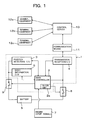
- FIG. 1 through FIG. 8 are drawings for describing the first embodiment of the present invention, in which FIG. 1 is an overall construction diagram of an antitheft system according to the first embodiment of the present invention, FIG. 2 is a block diagram of a main controller constructing the antitheft system shown in FIG. 1, FIG. 3 is a block diagram of a position detecting control unit, FIG. 4 is a block diagram of a body information control unit, FIG. 5 is a flow chart of processing operations until a first predetermined time Ts elapses since the input of an engine stop signal, FIG. 6 is a flow chart of processing operations after Ts has elapsed subsequent to the stopping of the engine, FIG. 7 is a flow chart of processingwhen an information demand signal has been inputted from a control server, and FIG. 8 is a time chart after the engine stop signal has been inputted.
- the antitheft system is provided with a control system 1 to be mounted on a self-propelling movable object, for example, a hydraulic excavator with an engine 7 mounted as a drive source thereon and also with a control server 10 for performing transmissions/receptions of information with the control system 1, which is located at a remote plate, via a wireless communication means 11 such as satellite communication or telephone line communication and also for managing a control of information on the hydraulic excavator.
- a control system 1 to be mounted on a self-propelling movable object, for example, a hydraulic excavator with an engine 7 mounted as a drive source thereon and also with a control server 10 for performing transmissions/receptions of information with the control system 1, which is located at a remote plate, via a wireless communication means 11 such as satellite communication or telephone line communication and also for managing a control of information on the hydraulic excavator.
- the control system 1 is provided with a position detecting control unit 3 for detecting the position of the hydraulic excavator by GPS, a body information control unit 5 for fetching signals from various sensors arranged on the hydraulic excavator and detecting and storing various information on operations of the hydraulic excavator, a transmission/reception control unit 4 for performing transmissions/receptions of information with the control server 10, and a main controller 2 for controlling the respective control units 3, 4, 5 systematically and performing predetermined processing operations.
- a position detecting control unit 3 for detecting the position of the hydraulic excavator by GPS
- a body information control unit 5 for fetching signals from various sensors arranged on the hydraulic excavator and detecting and storing various information on operations of the hydraulic excavator
- a transmission/reception control unit 4 for performing transmissions/receptions of information with the control server 10
- a main controller 2 for controlling the respective control units 3, 4, 5 systematically and performing predetermined processing operations.
- the position detecting control unit 3 and body information control unit 5 are connected to the battery 6 via a switch 9 as a first power feeding means, while the main controller 2 and transmission/reception control unit 4 are connected to the battery 6 via a switch 8 as a second power feeding means.
- terminal equipment 12a, 12b, 12c are connected via a network to permit an access by the owner, maker, service mechanic or the like of the hydraulic excavator to the control server 10 for the confirmation of an operation state of the hydraulic excavator.
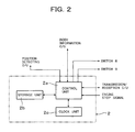
- the main controller 2 is provided, as shown in FIG. 2, with a control unit 2a comprising a CPU to control the above-mentioned, respective control units 3,4,5, switch 8 and switch 9 systematically and to perform predetermined processing operations, a storage unit 2b for storing processing results temporarily in the course of processing operations and also storing various parameters and the like, and a clock unit 2c as a clocking means.
- a control unit 2a comprising a CPU to control the above-mentioned, respective control units 3,4,5, switch 8 and switch 9 systematically and to perform predetermined processing operations
- a storage unit 2b for storing processing results temporarily in the course of processing operations and also storing various parameters and the like
- a clock unit 2c as a clocking means.
- signals relating to an operation or stop of the engine 7 are also inputted.
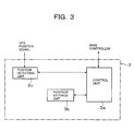
- the position detecting control unit 3 is provided, as shown in FIG. 3, a position detecting control unit 3c for capturing signals from unillustrated GPS satellites and calculating the position of the hydraulic excavator, a storage unit 3b for storing the thus-detected position information and a preset operable area for the hydraulic excavator, and a control unit 3a for performing transmissions/receptions of signals with the main controller 2, reading results of a detection by the position detecting unit 3c, andperformingprocessing to store the results of the detection in the storage unit 3b.
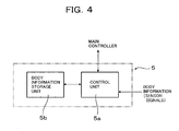
- the body information control unit 5 is provided, as shown in FIG. 4, with a control unit 5a for performing transmissions/receptions of signals with the main controller 2 and fetching information from the unillustrated various sensors mounted on the hydraulic excavator, and a storage unit 5b for storing the information fetched from the sensors.
- the switch 8 and switch 9 always maintain their turned-on positions so that power is fed to the respective control units 3,4,5 and the main controller 2.
- the position detecting unit 3c which constructs the position detecting control unit 3, no matter whether or not there is an instruction signal from the control unit 3a, calculates the current position of the hydraulic excavator from signals from the GPS satellites upon capturing the signals, and outputs the results to the control unit 3a.
- the control unit 3a compares the inputted current position with the operable area stored in the storage unit 3b and, when the current position departs from the operable area, outputs information on the current position and a theft signal to the main controller 2.
- position information calculated based on processing at the control unit 3a is stored in the storage unit 3b.
- This instruction signal from the main controller 2 is designed such that it is inputted at preset time intervals, for example, every hour. It is, however, also possible to store such position information whenever calculated, without relying upon instructions from the main controller 2.
- the body information control unit 5 progressively stores signals, which are fed in predetermined sampling cycles from the various sensors, in time sequence in the storage unit 5b via the control unit 5a.
- the abnormality signal is immediately outputted to the main controller 2.
- the main controller 2 When the theft signal has been inputted from the position detecting control unit 3 or the abnormality signal has been inputted from the body information control unit 5, the main controller 2 outputs an instruction signal to the transmission/reception control unit 4 to transmit the signal to the control server 10.
- the main controller 2 instructs to send the position information and body information, which are stored in the position detecting control unit 3 and body information control unit 5, respectively, to the main controller 2, inputs these information, and outputs an instruction signal to the transmission/reception control unit 4 such that they are transmitted to the control server 10.
- the transmission/reception control unit 4 transmits the position information, theft signal, body information, abnormality information or the like to the control server 10 via the communication means 11.
- the main controller 2 reads in the first Step S1 the latest position information stored in the storage unit 3b of the position detection control unit 3, and in the next Step S2, stores the thus-read position information (X0, Y0) in the storage unit 2b of the main controller 2.
- the time T0 at which the stop signal of the engine 7 was inputted is read from the clock unit 2c in the next Step S3, and is stored in the storage unit 2b in Step S4.
- Step S5 a current time T1 is read from the clock unit 2b, and in the next Step S6, a determination is made as to whether or not a predetermined time Ts, for example, 3 hours or so have elapsed from the input of the stop signal of the engine 7. If not determined to have elapsed, the routine moves to Step S7.
- a predetermined time Ts for example, 3 hours or so have elapsed from the input of the stop signal of the engine 7. If not determined to have elapsed, the routine moves to Step S7.
- Step S7 current position information (X1,Y1) is read from the position detecting control unit 3, and in the next Step S8, the distance ⁇ L from the position (X0,Y0) at the time point of the input of the stop signal of the engine 7 is calculated. It is then determined in the next Step S9 whether or not the thus-calculated distance ⁇ L is greater than a predetermined distance Ls. When the distance ⁇ L is determined to be smaller than the predetermined distance Ls in Step S9, the hydraulic excavator is not determined to have been stolen, the routine returns to Step S5 and the processing operations of Steps S5 to S9 are repeated.
- Step S10 When the thus-calculated distance ⁇ L is determined to be equal to or greater than the predetermined distance Ls in Step S9, the routine moves to Step S10. After an instruction signal is outputted to the transmission/reception control unit 4 such that a theft signal and the position information (X1,Y1) at that time are transmitted to the control server 10, the routine returns to Step S7 and the processing operations of Step S7 to Step S10 are repeatedly performed.
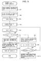
- Step S11 When the predetermined time Ts is determined to have elapsed after the input of the stop signal of the engine 7 in Step S6, the routine moves to Step S11, and the body information stored in the storage unit 5b of the body information control unit 5 is read and is once stored in the storage unit 2b.
- Step S12 an instruction signal is outputted to the transmission/reception control unit 4 such that the stored body information, current time T1 and position information (X1,Y1) are transmitted to the control server 10.
- Step S13 a turn-off signal is outputted to the switch 9 so that the feeding of power to the position detecting control unit 3 and body information control unit 5 is cut off.
- the switch 9 retains its turned-on position until the predetermined time Ts elapses after the input of the stop signal from the engine 7. During this period, it is possible to ascertain whether or not the hydraulic excavator has been stolen in a similar manner as in the time of an operation of the engine. When determined to have been stolen, a report can be immediately made to the control server 10 located at the remote place.
- the switch retains its turned-on position even after the predetermined time Ts has elapsed subsequent to the input of the stop signal from the engine 7. Power is, therefore, still continuously fed from the battery 6 to the main controller 2 and transmission/reception control unit 4.
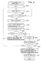
- a variable N for counting is set at 0, and in the next Step S21, the current time T2 is read from the clock unit 2c.
- Step S22 a determination is made as to whether or not a predetermined time interval ⁇ T has elapsed from the time of the preceding processing.
- ⁇ T is not determined to have elapsed
- the routine returns to Step S21.
- ⁇ T is determined to have elapsed
- the routine advances to the next Step S23.
- Step S23 an instruction signal is outputted to turn on the switch which has been in the turned-off position.
- power is fed to the position detecting control unit 3, and at the position detecting control unit 3, the position is detected and the current position information (X1,Y1) is outputted to the main controller 2.
- Step S24 the thus-outputted current position information (X1, Y1) is read, and in the next Step S2 5, the distance ⁇ L from the position (X0, Y0) at which the stop signal of the engine 7 was inputted is calculated.
- Step S26 a determination is made as to whether or not the thus-calculated distance ⁇ L is greater than the predetermined distance Ls. When determined to be smaller, the routine moves to Step S27.
- Step S27 1 is added to the variable N, and in the next Step S28, a signal is outputted to turn off the switch 9. As a result, the feeding of power to the position detecting control unit 3 is cut off.
- Step S29 a determination is made as to whether or not the processing operations from Steps S21 to S27 have reached a predetermined number of times NO.
- N0 has not been reached yet, the routine is returned to Step S21.
- Step S25 When the distance ⁇ L calculated in Step S25 is determined to be greater than the predetermined distance Ls in Step S26, the routine moves to Step S32, and an instruction signal is outputted to the transmission/reception control unit 4 such that a theft signal and the position information (X1, Y1) at that time are transmitted to the control server 10.
- this instruction signal When this instruction signal is inputted, the transmission/reception control unit 4 transmits the current position information (X1,Y1) together with the theft signal to the control server 10.
- Step S30 When the number of processing operations, N, is determined to have reached N0 in Step S29, on the other hand, the routine moves to Step S30, and an instruction signal is outputted to the transmission/reception control unit 4 such that a signal to the effect that the transmission/reception processing is to end is transmitted together with the current position information (X1,Y1) to the control server 10.
- this indication signal is inputted, the transmission/reception control unit transmits a signal, which informs the control server 10 to the effect that the transmission/reception processing has ended, together with the current position information (X1, Y1) to the control server 10.
- Step S31 a turn-off signal is outputted to the switch S8.
- the feeding of power to the main controller 2 and transmission/reception control unit 4 is cut off so that at the control system 1, processing operations and transmissions/receptions with the outside are disabled.
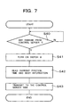
- Step S42 the current position information is read from the position detecting control unit 3, and further, body information is read from the body information control unit 5 and the current time is also read from the clock unit 2c.
- an instruction signal is outputted to the transmission/reception control unit 4 such that they are transmitted to the control server 10.
- the transmission/reception control unit 4 transmits the position information and body information together with the current time to the control server 10.
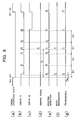
- FIG. 8 is a time chart which shows in time sequence the processing operations in FIG. 5 to FIG. 7.
- the switch 9 and switch 8 continuously retain their turned-on positions until the first predetermined time Ts elapses subsequent to the input of a stop signal (key off) of the engine 7 ((b), (c)), and after an elapse of Ts, the position information and body information on the hydraulic excavator are transmitted to the control server ((e),(f),(g)), and the switch 9 is turned off ((b)).
- the turn-on and turn-off of the switch 9 are repeated at the predetermined time intervals ⁇ t ((b)) and, whenever the switch 9 is brought into its turned-on position, the detection of a position at that time point is performed ((e)).
- the predetermined time intervals ⁇ t reach a predetermined number of times N0 (4 times in FIG. 8)
- the position information and a signal that indicates the end of the transmission/reception processing are fed to the control server 10 ((g)), and the switch 8 and switch 9 are brought into their cut-off positions ((b),(c)).
- power is, therefore, intermittently transmitted from the battery 6 to the position detecting control unit 3 and body information control unit 5 via the switch 9 after the first predetermined time Ts has elapsed subsequent to a stop of the engine 7. It is, accordingly, possible to cut down the consumption of as much power at the position detecting control unit 3 and body information control unit 5 as the stop of the feeding of power. As a consequence, it is possible to prolong the time until the battery mounted on the hydraulic excavator comes into the state of a battery drainage.
- control system 1 mounted on the hydraulic excavator, it is also possible to determine despite the stopping of the engine 7 whether or not the hydraulic excavator has been moved, in other words, stolen. Because a report is made to the side of the control server 10 via the transmission/reception control unit 4 only when the hydraulic excavator is determined to have been stolen, the number of communications with the control server 10 can be reduced so that the communication cost can be kept low.
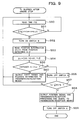
- the above-described first embodiment is designed such that, after the predetermined time Ts has elapsed subsequent to the input of the stop signal of the engine 7, the switch 9 is intermittently turned on and off only the predetermined number of times N0 at predetermined time intervals ⁇ t and a positional detection is performed every time the switch 9 is turned on. Instead of the predetermined number of times N0, however, it is also possible to intermittently turn on and off the switch 9 at predetermined time intervals ⁇ t until a second predetermined time Ts' elapses subsequent to the input of the stop signal of the engine 7. This processing is shown in FIG. 9.
- Step S57 a determination is made as to whether or not the second predetermined time Ts' has elapsed after the input of the stop signal from the engine 7. When not determined to have elapsed, the routine returns to the first Step S50 and Step S50 to Step S57 are performed again.
- an instruction signal is outputted such that position information (X1, Y2) and a signal to the effect that the transmission/reception processing is to end are transmitted to the control server 10, and a turn-off signal is outputted to the switch 8 (Step S58 and Step S59).
- the main controller 2 is provided with the clock unit 2c and power is fed from the battery 6 to the main controller 2 and clock unit 2c via the switch 8.
- a clocking means independently of the main controller 2 and to feed power to the clocking means, for example, by a lithium battery different from the battery mounted on the hydraulic excavator.
- FIG. 10 (h) it is also possible, as illustrated in FIG. 10 (h), to provide the clocking means with a timer function such that an ON signal is outputted at predetermined time intervals ⁇ t and based on the ON signal, a turn-on signal is outputted to the switch 9.
- the lithium battery serves as a second power feeding means.
Abstract
Description
- This invention relates to an antitheft system, which is arranged on a self-propelling movable object including a
- construction machine such as a hydraulic excavator and makes it possible to ascertain the position of the movable object on the side of a control server located at a place remote from the movable object.
- As an antitheft system of this type, there is disclosed, for example, in JP 2000-73411 A a technology that detects, for example, by a global positioning system, i.e., GPS the position of a hydraulic excavator as a self-propelling movable object under control, transmits by wireless communication the thus-detected position of the hydraulic excavator to a control server located at a remote place, and ascertains by the control server whether or not the position of the hydraulic excavator is within a predetermined normal work area.
- According to this conventional technology, when the position of the hydraulic excavator as detected by GPS has been determined to depart from the normal work area, an engine stop signal is transmitted from the control server to a control system mounted on the hydraulic excavator to stop an operation of the hydraulic excavator.
- As described above, the conventional technology makes it possible to promptly infer the theft of the hydraulic excavator and to disable work such as digging or running by the hydraulic excavator and, because the hydraulic excavator becomes no longer possible of self-propelling, also makes it difficult to load the hydraulic excavator on a vehicle for carrying it away, for example, a trailer. Accordingly, the conventional technology can scare away a potential thief and practically, can make it difficult to steal, thereby serving as an effective technology for the prevention of a theft.
- Among self-propelling movable objects, construction machines such as hydraulic excavators, in particular, are often stolen at night after finishing work. While being transported on a trailer or the like, the engine of the hydraulic excavator is in a stopped state. There is, accordingly, a need for the development of a countermeasure for a theft while the engine is stopped. In the above-described conventional technology, no reference is specifically made as to the time during which the engine is stopped. When constructed, for example, to continuously feed power to a control system, which performs positional detections and transmissions/receptions to/from a control server, always including the time during which the engine is stopped, the voltage of a power supply, i. e. , a battery mounted on the hydraulic excavator, however, drops (undergoes a battery drainage) in a short time so that frequent recharging is required. When constructed, as in the conventional technology, to transmit the position information on the hydraulic excavator to the side of the control server and to determine on the side of the control server whether or not the hydraulic excavator has departed from a normal work area, on the other hand, the number of communications between the hydraulic excavator and the control server becomes great, resulting in a substantial communication cost. Therefore, a problem also remains unsolved in this respect.
- The present invention has been completed in view of the above-described problems of the conventional technology. A first object of the present invention is, therefore, to provide an antitheft system which can ascertain the position of a movable object even during stopping of an engine while reducing the consumption of power by a control system during the stopping of the engine and avoiding a battery drainage. Further, a second obj ect of the present invention is to provide an antitheft system which can keep the communication cost low by minimizing the number of communications with a control server.
- To achieve the first object, the present invention is characterized in that in an antitheft system provided with a control system arranged on a self-propelling movable object with an engine mounted thereon as a drive source and having a position detecting means for detecting a position of the movable object, a transmission/reception means for performing a transmission/reception to/from an outside and a processingmeans for performing predetermined processing operations including outputs of run commands to the position detecting means and the transmission/reception means and a control server arranged at a place different from the movable object for controlling information on the movable object, said information comprising position information detected by the position detecting means and transmitted via the transmission/reception means, the antitheft system comprises a clocking means, a first power feeding means for performing feeding of power to at least the position detecting means, and a second power feeding means for performing feeding of power to at least the clocking means, and the processing means receives signals from the clocking means, allows the first power feeding means to continuously feed power until a first predetermined time elapses from a time point at which a stop signal for the engine is inputted, and after an elapse of the first predetermined time, repeatedly outputs an instruction signal, which permits feeding of power, at predetermined time intervals to the first power feeding means.
- By constructing as described above, the current position of the movable object can be detected by the position detecting means in a similar manner as in the time of an operation of the engine until the first predetermined time elapses from a time point at which the engine is stopped. After the elapse of the first predetermined time, the feeding of power by the first power feeding means is stopped so that the feeding of power to the position detecting means is stopped. To the clocking means, however, power is continuously fed from the second power feeding means. Based on signals from the clocking means, power is fed at the predetermined time intervals from the first power feeding means to the position detecting means so that a positional detection is performed intermittently. Namely, power is intermittently fed from the first power feeding means to the position detecting means after the elapse of the first predetermined time. The consumption of power at the position detectingmeans can, therefore, be cut down as much as the stopping of power feeding.
- It is, therefore, possible to prolong the time until the battery mounted on the movable object comes into the state of a battery drainage.
- On the other hand, the invention described in
claim 5 to achieve the second object is characterized in that the control system is provided with a storage means for storing the position information on the movable object as detected by the position detecting means, and the processing means compares position information, which has been detected subsequent to the input of the stop signal for the engine, with the position information stored in the storage means and, when a distance difference of at least a predetermined value is confirmed, determines that the movable object has been stolen, and instructs the transmission/reception means to transmit a theft signal together with the position information to the control server. - By constructing as described above, whether or not the movable object has been moved, in other words, stolen can be determined despite the stopping of the engine by the control system mounted on the movable object. Because a report is made to the side of the control server via the transmission/reception means only when a theft has been determined, the number of communications with the control server can be reduced so that the communication cost can be kept low.
- As described above in detail, the present invention can detect the current position of the movable obj ect by the position detecting means in a similar manner as in the time of an operation of the engine until the first predetermined time elapses from a time point at which the engine is stopped, and after the elapse of the first predetermined time, can feed power at the predetermined time intervals from the first power feeding means to the position detecting means so that a positional detection can be performed intermittently. Namely, power is intermittently fed from the first power feeding means to the position detecting means after the elapse of the first predetermined time. The consumption of power at the position detecting means can, therefore, be cut down as much as the stopping of power feeding. Accordingly, it is possible to prolong the time until the battery mounted on the movable object comes into the state of a battery drainage.
- Further, whether or not the movable object has been stolen can be determined by the control system mounted on the movable object and, only when a theft has been determined, a report is made to the side of the control server via the transmission/reception means. Accordingly, the number of communications with the control server can be reduced so that the communication cost can be kept low.
-
- FIG. 1 is an overall construction diagram of an antitheft system according to an embodiment of the present invention.
- FIG. 2 is a block diagram of a main controller shown in FIG. 1.
- FIG. 3 is a block diagram of a position detecting control unit shown in FIG. 1.
- FIG. 4 is a block diagram of a body information control unit shown in FIG. 1.
- FIG. 5 is a flow chart showing the details of processing operations until a first predetermined time elapses since the input of an engine stop signal.
- FIG. 6 is a flow chart showing the details of processing operations after the first predetermined time has elapsed subsequent to the input of the engine stop signal.
- FIG. 7 is a flow chart showing processing when an information demand signal has been inputted from a control server.
- FIG. 8 is a time chart after the engine stop signal has been inputted.
- FIG. 9 is a flow chart illustrating a modification of the processing in the first embodiment as shown in FIG. 6.
- FIG. 10 is a time chart illustrating a modification of the time chart for the first embodiment as shown in FIG. 8.
-
- Based on the drawings, a description will hereinafter be made about the embodiment of the present invention.
- FIG. 1 through FIG. 8 are drawings for describing the first embodiment of the present invention, in which FIG. 1 is an overall construction diagram of an antitheft system according to the first embodiment of the present invention, FIG. 2 is a block diagram of a main controller constructing the antitheft system shown in FIG. 1, FIG. 3 is a block diagram of a position detecting control unit, FIG. 4 is a block diagram of a body information control unit, FIG. 5 is a flow chart of processing operations until a first predetermined time Ts elapses since the input of an engine stop signal, FIG. 6 is a flow chart of processing operations after Ts has elapsed subsequent to the stopping of the engine, FIG. 7 is a flow chart of processingwhen an information demand signal has been inputted from a control server, and FIG. 8 is a time chart after the engine stop signal has been inputted.
- As shown in FIG. 1, the antitheft system according to this embodiment is provided with a
control system 1 to be mounted on a self-propelling movable object, for example, a hydraulic excavator with anengine 7 mounted as a drive source thereon and also with acontrol server 10 for performing transmissions/receptions of information with thecontrol system 1, which is located at a remote plate, via a wireless communication means 11 such as satellite communication or telephone line communication and also for managing a control of information on the hydraulic excavator. - The
control system 1 is provided with a position detectingcontrol unit 3 for detecting the position of the hydraulic excavator by GPS, a bodyinformation control unit 5 for fetching signals from various sensors arranged on the hydraulic excavator and detecting and storing various information on operations of the hydraulic excavator, a transmission/reception control unit 4 for performing transmissions/receptions of information with thecontrol server 10, and amain controller 2 for controlling therespective control units - To the
respective control units main controller 2, power is fed by abattery 6 mounted on the hydraulic excavator. In this embodiment, the position detectingcontrol unit 3 and bodyinformation control unit 5 are connected to thebattery 6 via aswitch 9 as a first power feeding means, while themain controller 2 and transmission/reception control unit 4 are connected to thebattery 6 via aswitch 8 as a second power feeding means. - To the
control server 10, on the other hand,terminal equipment control server 10 for the confirmation of an operation state of the hydraulic excavator. - The
main controller 2 is provided, as shown in FIG. 2, with acontrol unit 2a comprising a CPU to control the above-mentioned,respective control units switch 8 and switch 9 systematically and to perform predetermined processing operations, astorage unit 2b for storing processing results temporarily in the course of processing operations and also storing various parameters and the like, and aclock unit 2c as a clocking means. In addition, signals relating to an operation or stop of theengine 7 are also inputted. - The position detecting
control unit 3 is provided, as shown in FIG. 3, a position detectingcontrol unit 3c for capturing signals from unillustrated GPS satellites and calculating the position of the hydraulic excavator, astorage unit 3b for storing the thus-detected position information and a preset operable area for the hydraulic excavator, and acontrol unit 3a for performing transmissions/receptions of signals with themain controller 2, reading results of a detection by theposition detecting unit 3c, andperformingprocessing to store the results of the detection in thestorage unit 3b. - The body
information control unit 5 is provided, as shown in FIG. 4, with acontrol unit 5a for performing transmissions/receptions of signals with themain controller 2 and fetching information from the unillustrated various sensors mounted on the hydraulic excavator, and astorage unit 5b for storing the information fetched from the sensors. - In the antitheft system according to this embodiment constructed as described above, while the
engine 7 is in operation, theswitch 8 andswitch 9 always maintain their turned-on positions so that power is fed to therespective control units main controller 2. - In this state, the
position detecting unit 3c which constructs the position detectingcontrol unit 3, no matter whether or not there is an instruction signal from thecontrol unit 3a, calculates the current position of the hydraulic excavator from signals from the GPS satellites upon capturing the signals, and outputs the results to thecontrol unit 3a. Thecontrol unit 3a compares the inputted current position with the operable area stored in thestorage unit 3b and, when the current position departs from the operable area, outputs information on the current position and a theft signal to themain controller 2. - When an instruction signal has been inputted form the
main controller 2, position information calculated based on processing at thecontrol unit 3a is stored in thestorage unit 3b. This instruction signal from themain controller 2 is designed such that it is inputted at preset time intervals, for example, every hour. It is, however, also possible to store such position information whenever calculated, without relying upon instructions from themain controller 2. - The body
information control unit 5 progressively stores signals, which are fed in predetermined sampling cycles from the various sensors, in time sequence in thestorage unit 5b via thecontrol unit 5a. On the other hand, when the coolant temperature of theengine 7 has become abnormally high and an abnormality signal serious for the operation of the hydraulic excavator such as falling of the rotational speed of theengine 7 below a predetermined lowest rotational speed has been inputted by so-called interrupting processing, the abnormality signal is immediately outputted to themain controller 2. - When the theft signal has been inputted from the position detecting
control unit 3 or the abnormality signal has been inputted from the bodyinformation control unit 5, themain controller 2 outputs an instruction signal to the transmission/reception control unit 4 to transmit the signal to thecontrol server 10. - When the transmission/
reception control unit 4 has received a data-demanding signal from thecontrol server 10 or when a predetermined time has been reached, themain controller 2 instructs to send the position information and body information, which are stored in the position detectingcontrol unit 3 and bodyinformation control unit 5, respectively, to themain controller 2, inputs these information, and outputs an instruction signal to the transmission/reception control unit 4 such that they are transmitted to thecontrol server 10. - When the instruction signal is inputted from the
main controller 2, the transmission/reception control unit 4 transmits the position information, theft signal, body information, abnormality information or the like to thecontrol server 10 via the communication means 11. - A description has been made about the processing by the
respective control units main controller 2 when theengine 7 is in operation. With reference to FIG. 5 through FIG. 8, a description will next be made about processing after a stop signal has been inputted into themain controller 2 from theengine 7. - When the stop signal of the
engine 7 has been inputted as illustrated in FIG. 5, themain controller 2 reads in the first Step S1 the latest position information stored in thestorage unit 3b of the positiondetection control unit 3, and in the next Step S2, stores the thus-read position information (X0, Y0) in thestorage unit 2b of themain controller 2. - The time T0 at which the stop signal of the
engine 7 was inputted is read from theclock unit 2c in the next Step S3, and is stored in thestorage unit 2b in Step S4. - In Step S5, a current time T1 is read from the
clock unit 2b, and in the next Step S6, a determination is made as to whether or not a predetermined time Ts, for example, 3 hours or so have elapsed from the input of the stop signal of theengine 7. If not determined to have elapsed, the routine moves to Step S7. - In Step S7, current position information (X1,Y1) is read from the position detecting
control unit 3, and in the next Step S8, the distance ΔL from the position (X0,Y0) at the time point of the input of the stop signal of theengine 7 is calculated. It is then determined in the next Step S9 whether or not the thus-calculated distance ΔL is greater than a predetermined distance Ls. When the distance ΔL is determined to be smaller than the predetermined distance Ls in Step S9, the hydraulic excavator is not determined to have been stolen, the routine returns to Step S5 and the processing operations of Steps S5 to S9 are repeated. - When the thus-calculated distance ΔL is determined to be equal to or greater than the predetermined distance Ls in Step S9, the routine moves to Step S10. After an instruction signal is outputted to the transmission/
reception control unit 4 such that a theft signal and the position information (X1,Y1) at that time are transmitted to thecontrol server 10, the routine returns to Step S7 and the processing operations of Step S7 to Step S10 are repeatedly performed. - When the predetermined time Ts is determined to have elapsed after the input of the stop signal of the
engine 7 in Step S6, the routine moves to Step S11, and the body information stored in thestorage unit 5b of the bodyinformation control unit 5 is read and is once stored in thestorage unit 2b. In Step S12, an instruction signal is outputted to the transmission/reception control unit 4 such that the stored body information, current time T1 and position information (X1,Y1) are transmitted to thecontrol server 10. In the next Step S13, a turn-off signal is outputted to theswitch 9 so that the feeding of power to the position detectingcontrol unit 3 and bodyinformation control unit 5 is cut off. - As described above, the
switch 9 retains its turned-on position until the predetermined time Ts elapses after the input of the stop signal from theengine 7. During this period, it is possible to ascertain whether or not the hydraulic excavator has been stolen in a similar manner as in the time of an operation of the engine. When determined to have been stolen, a report can be immediately made to thecontrol server 10 located at the remote place. - With reference to FIG. 6, a description will next be made about the details of processing after the predetermined time Ts has elapsed after the input of the stop signal of the
engine 7. - As described above, the switch retains its turned-on position even after the predetermined time Ts has elapsed subsequent to the input of the stop signal from the
engine 7. Power is, therefore, still continuously fed from thebattery 6 to themain controller 2 and transmission/reception control unit 4. In the first Step S20 after the predetermined time Ts has elapsed, a variable N for counting is set at 0, and in the next Step S21, the current time T2 is read from theclock unit 2c. - In the next Step S22, a determination is made as to whether or not a predetermined time interval ΔT has elapsed from the time of the preceding processing. When ΔT is not determined to have elapsed, the routine returns to Step S21. When ΔT is determined to have elapsed, on the other hand, the routine advances to the next Step S23.
- In Step S23, an instruction signal is outputted to turn on the switch which has been in the turned-off position. As a result, power is fed to the position detecting
control unit 3, and at the position detectingcontrol unit 3, the position is detected and the current position information (X1,Y1) is outputted to themain controller 2. - In Step S24, the thus-outputted current position information (X1, Y1) is read, and in the
next Step S2 5, the distance ΔL from the position (X0, Y0) at which the stop signal of theengine 7 was inputted is calculated. In Step S26, a determination is made as to whether or not the thus-calculated distance ΔL is greater than the predetermined distance Ls. When determined to be smaller, the routine moves to Step S27. - In Step S27, 1 is added to the variable N, and in the next Step S28, a signal is outputted to turn off the
switch 9. As a result, the feeding of power to the position detectingcontrol unit 3 is cut off. - In the next Step S29, a determination is made as to whether or not the processing operations from Steps S21 to S27 have reached a predetermined number of times NO. When N0 has not been reached yet, the routine is returned to Step S21.
- When the distance ΔL calculated in Step S25 is determined to be greater than the predetermined distance Ls in Step S26, the routine moves to Step S32, and an instruction signal is outputted to the transmission/
reception control unit 4 such that a theft signal and the position information (X1, Y1) at that time are transmitted to thecontrol server 10. When this instruction signal is inputted, the transmission/reception control unit 4 transmits the current position information (X1,Y1) together with the theft signal to thecontrol server 10. - When the number of processing operations, N, is determined to have reached N0 in Step S29, on the other hand, the routine moves to Step S30, and an instruction signal is outputted to the transmission/
reception control unit 4 such that a signal to the effect that the transmission/reception processing is to end is transmitted together with the current position information (X1,Y1) to thecontrol server 10. When this indication signal is inputted, the transmission/reception control unit transmits a signal, which informs thecontrol server 10 to the effect that the transmission/reception processing has ended, together with the current position information (X1, Y1) to thecontrol server 10. - In the next Step S31, a turn-off signal is outputted to the switch S8. As a result, the feeding of power to the
main controller 2 and transmission/reception control unit 4 is cut off so that at thecontrol system 1, processing operations and transmissions/receptions with the outside are disabled. - With reference to FIG. 7, a description will be made about processing operations when the transmission/
reception control unit 4 has received a data-demanding signal from thecontrol server 10 at a stage preceding the output of the cut-off signal to theswitch 8. As illustrated in FIG. 7, a turn-on signal is outputted to theswitch 9 in Step S41 when the demand signal is inputted from thecontrol server 10. - When the
switch 9 is brought into the turned-on position and power is fed to the position detectingcontrol unit 3 and bodyinformation control unit 5, the detection of a position at that time point is performed at the position detectingcontrol unit 3. - In the next Step S42, the current position information is read from the position detecting
control unit 3, and further, body information is read from the bodyinformation control unit 5 and the current time is also read from theclock unit 2c. In the next Step S43, an instruction signal is outputted to the transmission/reception control unit 4 such that they are transmitted to thecontrol server 10. When this instruction signal is inputted, the transmission/reception control unit 4 transmits the position information and body information together with the current time to thecontrol server 10. - FIG. 8 is a time chart which shows in time sequence the processing operations in FIG. 5 to FIG. 7. As also shown in FIG. 8, in this embodiment, the
switch 9 andswitch 8 continuously retain their turned-on positions until the first predetermined time Ts elapses subsequent to the input of a stop signal (key off) of the engine 7 ((b), (c)), and after an elapse of Ts, the position information and body information on the hydraulic excavator are transmitted to the control server ((e),(f),(g)), and theswitch 9 is turned off ((b)). After that, the turn-on and turn-off of theswitch 9 are repeated at the predetermined time intervals Δt ((b)) and, whenever theswitch 9 is brought into its turned-on position, the detection of a position at that time point is performed ((e)). When the predetermined time intervals Δt reach a predetermined number of times N0 (4 times in FIG. 8), the position information and a signal that indicates the end of the transmission/reception processing are fed to the control server 10 ((g)), and theswitch 8 andswitch 9 are brought into their cut-off positions ((b),(c)). - In this embodiment, power is, therefore, intermittently transmitted from the
battery 6 to the position detectingcontrol unit 3 and bodyinformation control unit 5 via theswitch 9 after the first predetermined time Ts has elapsed subsequent to a stop of theengine 7. It is, accordingly, possible to cut down the consumption of as much power at the position detectingcontrol unit 3 and bodyinformation control unit 5 as the stop of the feeding of power. As a consequence, it is possible to prolong the time until the battery mounted on the hydraulic excavator comes into the state of a battery drainage. - With the
control system 1 mounted on the hydraulic excavator, it is also possible to determine despite the stopping of theengine 7 whether or not the hydraulic excavator has been moved, in other words, stolen. Because a report is made to the side of thecontrol server 10 via the transmission/reception control unit 4 only when the hydraulic excavator is determined to have been stolen, the number of communications with thecontrol server 10 can be reduced so that the communication cost can be kept low. - The above-described first embodiment is designed such that, after the predetermined time Ts has elapsed subsequent to the input of the stop signal of the
engine 7, theswitch 9 is intermittently turned on and off only the predetermined number of times N0 at predetermined time intervals Δt and a positional detection is performed every time theswitch 9 is turned on. Instead of the predetermined number of times N0, however, it is also possible to intermittently turn on and off theswitch 9 at predetermined time intervals Δt until a second predetermined time Ts' elapses subsequent to the input of the stop signal of theengine 7. This processing is shown in FIG. 9. - The flow chart shown in FIG. 9 is equal to the processing shown in FIG. 6 except for Step S57. In Step S57, a determination is made as to whether or not the second predetermined time Ts' has elapsed after the input of the stop signal from the
engine 7. When not determined to have elapsed, the routine returns to the first Step S50 and Step S50 to Step S57 are performed again. When the predetermined time Ts' is determined to have elapsed in Step S57, on the other hand, an instruction signal is outputted such that position information (X1, Y2) and a signal to the effect that the transmission/reception processing is to end are transmitted to thecontrol server 10, and a turn-off signal is outputted to the switch 8 (Step S58 and Step S59). By the processing shown in FIG. 9, it is, therefore, also possible to bring about similar advantageous effects as the first embodiment. - In the above-described first embodiment, it is constructed that the
main controller 2 is provided with theclock unit 2c and power is fed from thebattery 6 to themain controller 2 andclock unit 2c via theswitch 8. As an alternative, it is also possible to arrange a clocking means independently of themain controller 2 and to feed power to the clocking means, for example, by a lithium battery different from the battery mounted on the hydraulic excavator. In this case, it is also possible, as illustrated in FIG. 10 (h), to provide the clocking means with a timer function such that an ON signal is outputted at predetermined time intervals Δt and based on the ON signal, a turn-on signal is outputted to theswitch 9. It is also possible to connect thebattery 6 to themain controller 2, position detectingcontroller unit 3, transmission/reception control unit 4 and bodyinformation control unit 5 via theswitch 8 alone and to intermittently feed power to themain controller 2 and therespective controller units
Claims (8)
- An antitheft system provided with:a control system arranged on a self-propelling movable obj ect with an engine mounted thereon as a drive source and having a position detecting means for detecting a position of said movable object, a transmission/reception means for performing a transmission/reception to/from an outside and a processing means for performing predetermined processing operations including outputs of run commands to said position detecting means and said transmission/reception means, anda control server arranged at a place different from said movable object for controlling information on saidmovable object, said information comprising position information detected by said position detecting means and transmitted via said transmission/reception means, characterized in that said antitheft system comprises:a clocking means, a first power feeding means for performing feeding of power to at least said position detecting means, and a second power feeding means for performing feeding of power to at least said clocking means; andsaid processing means receives signals from said clocking means, allows said first power feeding means to continuously feed power until a first predetermined time elapses from a time point at which a stop signal for said engine is inputted, and after an elapse of said first predetermined time, repeatedly outputs an instruction signal, which permits feeding of power, at predetermined time intervals to said first power feeding means.
- An antitheft system according to claim 1, wherein said processing means reads said position information on said movable object as detected by said position detecting means whenever said instruction signal, which permits said feeding of power, is outputted at said predetermined time intervals to said first power feeding means, and after completion of said reading of said position information, instructs said first power feeding means to stop feeding of power.
- An antitheft system according to claim 2, wherein, when said command signal which permits feeding of power has been outputted a predetermined number of times at said predetermined time intervals to said first power feeding means, said processing means instructs said transmission/reception means to transmit said position information on said movable object, which was detected lastly by said position detecting means, and a signal, which communicates that a transmission/reception to/from said outside via said transmission/reception means is disabled, to said control server.
- An antitheft system according to claim 2, wherein, when a second predetermined time has elapsed subsequent to an elapse of said first predetermined time, said processing means instructs said transmission/reception means to transmit said position information on said movable object, which was detected lastly by said position detecting means, and a signal, which communicates that a transmission/reception to/from said outside via said transmission/reception means is disabled, to said control server.
- An antitheft system according to claim 1, wherein said control system is provided with a storage means for storing said position information on said movable object as detected by said position detecting means; and said processing means compares position information, which has been detected subsequent to said input of said stop signal for said engine, with said position information stored in said storage means and, when a distance difference of at least a predetermined value is confirmed, determines that said movable object has been stolen, and instructs said transmission/reception means to transmit a theft signal together with said position information to said control server.
- An antitheft system according to claim 3 or 4, wherein, when said movable object is determined to have been stolen, said processing means outputs an instruction signal, which permits continuous feeding of power, to said first power feeding means.
- An antitheft system according to claim 5, wherein said second power feeding means is connected to perform feeding of power to said transmission/reception means; and, when said instruction signal has been inputted from said control server via said transmission/reception means before a transmission/reception to/from said outside via said transmission/reception means is disabled, said processing means instructs said transmission/reception means to transmit at least said position information, which has been stored in said storage means, to a side of said control server.
- An antitheft system according to claim 7, wherein, when a signal communicating that a transmission/reception is disabled has been transmitted to said control server via said transmission/reception means, said processing means instructs said second power feeding means to stop feeding of power.
Applications Claiming Priority (3)
| Application Number | Priority Date | Filing Date | Title |
|---|---|---|---|
| JP2002363947 | 2002-12-16 | ||
| JP2002363947A JP3839400B2 (en) | 2002-12-16 | 2002-12-16 | Anti-theft device |
| PCT/JP2003/016096 WO2004054854A1 (en) | 2002-12-16 | 2003-12-16 | Antitheft device |
Publications (3)
| Publication Number | Publication Date |
|---|---|
| EP1577180A1 true EP1577180A1 (en) | 2005-09-21 |
| EP1577180A4 EP1577180A4 (en) | 2006-04-05 |
| EP1577180B1 EP1577180B1 (en) | 2016-08-10 |
Family
ID=32588221
Family Applications (1)
| Application Number | Title | Priority Date | Filing Date |
|---|---|---|---|
| EP03780781.5A Expired - Lifetime EP1577180B1 (en) | 2002-12-16 | 2003-12-16 | Antitheft device |
Country Status (6)
| Country | Link |
|---|---|
| US (1) | US7489049B2 (en) |
| EP (1) | EP1577180B1 (en) |
| JP (1) | JP3839400B2 (en) |
| KR (1) | KR100689938B1 (en) |
| CN (1) | CN1330518C (en) |
| WO (1) | WO2004054854A1 (en) |
Cited By (1)
| Publication number | Priority date | Publication date | Assignee | Title |
|---|---|---|---|---|
| EP1982880A1 (en) * | 2006-02-06 | 2008-10-22 | Komatsu Ltd. | Moving object monitoring device and moving object monitoring system |
Families Citing this family (13)
| Publication number | Priority date | Publication date | Assignee | Title |
|---|---|---|---|---|
| AU2005275036A1 (en) | 2004-07-15 | 2006-02-23 | Amgen Inc. | 1,2,3,4-tetrahydropyrazin-2-yl acetamides and their use as bradykinin antagonists for the treatment of inflammation related disorders |
| JP4788756B2 (en) * | 2004-08-24 | 2011-10-05 | 株式会社デンソー | Vehicle receiver |
| JP4213151B2 (en) * | 2005-09-07 | 2009-01-21 | 俊彦 水上 | Portable communication terminal with GPS function |
| JP2007276573A (en) * | 2006-04-04 | 2007-10-25 | Denso Corp | Vehicle theft detecting device |
| EP2026288A3 (en) * | 2007-08-03 | 2010-11-24 | Denso Corporation | Electronic control system and method for vehicle diagnosis |
| US20120226410A1 (en) * | 2011-03-04 | 2012-09-06 | Continental Automotive Systems, Inc. | System and method for minimizing the power drain on a battery of a vehicle |
| CN103085758B (en) * | 2011-10-28 | 2016-10-12 | 上海博泰悦臻网络技术服务有限公司 | Car-mounted terminal and vehicle monitoring system |
| CN103577208B (en) * | 2012-08-03 | 2016-09-07 | 纬创资通股份有限公司 | Perform the method for server switching on and shutting down and perform the system of server switching on and shutting down |
| JP6766689B2 (en) * | 2017-02-28 | 2020-10-14 | ブラザー工業株式会社 | Relocation detection device, relocation detection system and relocation detection method |
| FR3064572B1 (en) * | 2017-04-04 | 2019-03-22 | Continental Automotive France | METHOD FOR TEMPORARILY INHIBITING REMOTE ACTIVATION OF A FUNCTION PRESENT IN A MOTOR VEHICLE |
| CN107088304A (en) * | 2017-05-24 | 2017-08-25 | 深圳市橙子兄弟信息科技有限公司 | Antitheft hand-car |
| CN113424238B (en) * | 2019-02-22 | 2022-09-13 | 本田技研工业株式会社 | Antitheft device and generator antitheft system |
| JP2022144383A (en) | 2021-03-19 | 2022-10-03 | 本田技研工業株式会社 | Working machine |
Citations (6)
| Publication number | Priority date | Publication date | Assignee | Title |
|---|---|---|---|---|
| US5223844A (en) * | 1992-04-17 | 1993-06-29 | Auto-Trac, Inc. | Vehicle tracking and security system |
| DE19733579A1 (en) * | 1997-08-02 | 1999-02-04 | Kdm Sicherheitstechnik Gmbh | Motor vehicle monitoring method |
| EP1178458A1 (en) * | 1999-03-17 | 2002-02-06 | Komatsu Ltd. | Device for presenting information to mobile |
| US20020091955A1 (en) * | 2001-01-05 | 2002-07-11 | Christopher Gary L. | Wake-up circuit for an electronic system and method therefor |
| US20020163449A1 (en) * | 2000-05-17 | 2002-11-07 | Flick Kenneth E. | Vehicle tracking unit for controling operable vehicle devices using a vehicle data bus and related methods |
| EP1414002A1 (en) * | 2001-07-12 | 2004-04-28 | Hitachi Construction Machinery Co., Ltd. | Method for locating construcion machine, position plotting system, and construction machine |
Family Cites Families (42)
| Publication number | Priority date | Publication date | Assignee | Title |
|---|---|---|---|---|
| JPH10133676A (en) | 1996-10-30 | 1998-05-22 | Pioneer Electron Corp | Information read control method |
| JPH10336760A (en) * | 1997-06-04 | 1998-12-18 | Omron Corp | Receiver and remote control device |
| US6522265B1 (en) * | 1997-06-25 | 2003-02-18 | Navox Corporation | Vehicle tracking and security system incorporating simultaneous voice and data communication |
| JP2000072727A (en) | 1998-08-25 | 2000-03-07 | Mitsui Chemicals Inc | Production of optically active alpha-substituted-bete- aminoketone derivative |
| JP2000073411A (en) | 1998-08-31 | 2000-03-07 | Yutani Heavy Ind Ltd | Burglary prevention device of construction machine and burglary prevention system |
| JP2997465B1 (en) * | 1999-03-11 | 2000-01-11 | 山一電機株式会社 | Method of forming conductive bumps on wiring board |
| JP2000295669A (en) * | 1999-04-07 | 2000-10-20 | Matsushita Electric Ind Co Ltd | On-vehicle terminal, information transfer system and emergency report system |
| US6611755B1 (en) * | 1999-12-19 | 2003-08-26 | Trimble Navigation Ltd. | Vehicle tracking, communication and fleet management system |
| JP3723837B2 (en) * | 2000-01-14 | 2005-12-07 | 富士通テン株式会社 | Theft reporting device and theft reporting system |
| US6974642B2 (en) | 2000-03-15 | 2005-12-13 | Fujitsu Limited | Carbonaceous protective layer, magnetic recording medium, production method thereof, and magnetic disk apparatus |
| US6809659B2 (en) * | 2000-05-17 | 2004-10-26 | Omega Patents, L.L.C. | Vehicle tracker with test features and related methods |
| US6765499B2 (en) * | 2000-05-17 | 2004-07-20 | Omega Patents, L.L.C. | Vehicle tracker unit providing variable frequency transmission and related methods |
| US6509868B2 (en) * | 2000-05-17 | 2003-01-21 | Omega Patents, L.L.C. | Vehicle tracker with user notifications and associated methods |
| US6804605B2 (en) * | 2000-05-17 | 2004-10-12 | Omega Patents, L.L.C. | Vehicle tracker with user registration reminder and related methods |
| US6798355B2 (en) * | 2000-05-17 | 2004-09-28 | Omega Patents, L.L.C. | Vehicle tracker including security device monitoring bypass feature and related methods |
| US6798356B2 (en) * | 2000-05-17 | 2004-09-28 | Omega Patents, L.L.C. | Vehicle tracking unit providing direction deviation tracking and related methods |
| US6771188B2 (en) * | 2000-05-17 | 2004-08-03 | Omega Patents, L.L.C. | Vehicle control system for controlling a vehicle function including a vehicle tracking unit and related methods |
| US6803861B2 (en) * | 2000-05-17 | 2004-10-12 | Omega Patents, L.L.C. | Vehicle tracking unit with fault condition diagnosis and related methods |
| US6693563B2 (en) * | 2000-05-17 | 2004-02-17 | Omega Patents, L.L.C. | Vehicle tracking unit providing theft alert notifications and related methods |
| US6606561B2 (en) * | 2000-05-17 | 2003-08-12 | Omega Patents, L.L.C. | Vehicle tracker including input/output features and related methods |
| US6744384B2 (en) * | 2000-05-17 | 2004-06-01 | Omega Patents, L.L.C. | Vehicle tracker having switchable polarity output terminals and related methods |
| US6512466B2 (en) * | 2000-05-17 | 2003-01-28 | Omega Patents, L.L.C. | Vehicle tracker with power saving features and related methods |
| US6741187B2 (en) * | 2000-05-17 | 2004-05-25 | Omega Patents, L.L.C. | Vehicle tracker providing vehicle alarm alert features and related methods |
| US6703946B2 (en) * | 2000-05-17 | 2004-03-09 | Omega Patents, L.L.C. | Vehicle tracking unit having a self diagnostic mode and related methods |
| US6844827B2 (en) * | 2000-05-17 | 2005-01-18 | Omega Patents, L.L.C. | Vehicle tracker including a connector for an upgrade device and related methods |
| US6522267B2 (en) * | 2000-05-17 | 2003-02-18 | Omega Patents, L.L.C. | Vehicle tracker conserving codes and related methods |
| US6737989B2 (en) * | 2000-05-17 | 2004-05-18 | Omega Patents, L.L.C. | Vehicle tracker including variable frequency transmission and related methods |
| US6819269B2 (en) * | 2000-05-17 | 2004-11-16 | Omega Patents, L.L.C. | Vehicle tracker including battery monitoring feature and related methods |
| US6507786B2 (en) * | 2000-05-17 | 2003-01-14 | Omega Patents, L.L.C. | Vehicle tracker with user registration reminder and related methods |
| US7031835B2 (en) * | 2000-05-17 | 2006-04-18 | Omega Patents, L.L.C. | Vehicle tracker cooperating with a starter interrupt and related methods |
| US6816089B2 (en) * | 2000-05-17 | 2004-11-09 | Omega Patents, L.L.C. | Vehicle tracker having find alert features and related methods |
| US6512465B2 (en) * | 2000-05-17 | 2003-01-28 | Omega Patents, L.L.C. | Vehicle tracker including stationary time determination and associated methods |
| US6765500B2 (en) * | 2000-05-17 | 2004-07-20 | Omega Patents, L.L.C. | Vehicle tracker including missed call feature and related methods |
| US6784809B2 (en) * | 2000-05-17 | 2004-08-31 | Omega Patents, L.L.C. | Vehicle tracker including override feature and related methods |
| JP2002127873A (en) * | 2000-10-27 | 2002-05-09 | Auto Network Gijutsu Kenkyusho:Kk | Checking system for automobile burglary prevention |
| CA2355426A1 (en) * | 2001-08-17 | 2003-02-17 | Luther Haave | A system and method for asset tracking |
| JP3603825B2 (en) * | 2001-08-27 | 2004-12-22 | オムロン株式会社 | Surveillance systems, central monitors, and on-board monitors |
| JP3635352B2 (en) * | 2002-06-24 | 2005-04-06 | オムロン株式会社 | Mobile theft detection device and theft detection method |
| US7110728B2 (en) * | 2003-01-23 | 2006-09-19 | Komatsu Ltd. | Mobile body communication device |
| US6856879B2 (en) * | 2003-01-24 | 2005-02-15 | Komatsu Ltd. | Work machine management device |
| US7183666B2 (en) * | 2003-01-24 | 2007-02-27 | Komatsu Ltd. | Movable body start-up locking device |
| KR20060016457A (en) * | 2004-08-17 | 2006-02-22 | 현대모비스 주식회사 | System and method for preventing robbery of a vehicle |
-
2002
- 2002-12-16 JP JP2002363947A patent/JP3839400B2/en not_active Expired - Lifetime
-
2003
- 2003-12-16 US US10/538,883 patent/US7489049B2/en active Active
- 2003-12-16 KR KR20057010908A patent/KR100689938B1/en active IP Right Grant
- 2003-12-16 EP EP03780781.5A patent/EP1577180B1/en not_active Expired - Lifetime
- 2003-12-16 WO PCT/JP2003/016096 patent/WO2004054854A1/en active Application Filing
- 2003-12-16 CN CNB2003801061106A patent/CN1330518C/en not_active Expired - Lifetime
Patent Citations (7)
| Publication number | Priority date | Publication date | Assignee | Title |
|---|---|---|---|---|
| US5223844A (en) * | 1992-04-17 | 1993-06-29 | Auto-Trac, Inc. | Vehicle tracking and security system |
| US5223844B1 (en) * | 1992-04-17 | 2000-01-25 | Auto Trac Inc | Vehicle tracking and security system |
| DE19733579A1 (en) * | 1997-08-02 | 1999-02-04 | Kdm Sicherheitstechnik Gmbh | Motor vehicle monitoring method |
| EP1178458A1 (en) * | 1999-03-17 | 2002-02-06 | Komatsu Ltd. | Device for presenting information to mobile |
| US20020163449A1 (en) * | 2000-05-17 | 2002-11-07 | Flick Kenneth E. | Vehicle tracking unit for controling operable vehicle devices using a vehicle data bus and related methods |
| US20020091955A1 (en) * | 2001-01-05 | 2002-07-11 | Christopher Gary L. | Wake-up circuit for an electronic system and method therefor |
| EP1414002A1 (en) * | 2001-07-12 | 2004-04-28 | Hitachi Construction Machinery Co., Ltd. | Method for locating construcion machine, position plotting system, and construction machine |
Non-Patent Citations (1)
| Title |
|---|
| See also references of WO2004054854A1 * |
Cited By (3)
| Publication number | Priority date | Publication date | Assignee | Title |
|---|---|---|---|---|
| EP1982880A1 (en) * | 2006-02-06 | 2008-10-22 | Komatsu Ltd. | Moving object monitoring device and moving object monitoring system |
| EP1982880A4 (en) * | 2006-02-06 | 2013-02-27 | Komatsu Mfg Co Ltd | Moving object monitoring device and moving object monitoring system |
| EP2891584A1 (en) * | 2006-02-06 | 2015-07-08 | Komatsu Ltd. | Moving object monitoring device and moving object monitoring system |
Also Published As
| Publication number | Publication date |
|---|---|
| KR100689938B1 (en) | 2007-03-12 |
| EP1577180A4 (en) | 2006-04-05 |
| JP3839400B2 (en) | 2006-11-01 |
| US7489049B2 (en) | 2009-02-10 |
| CN1330518C (en) | 2007-08-08 |
| WO2004054854A1 (en) | 2004-07-01 |
| KR20050084301A (en) | 2005-08-26 |
| JP2004199167A (en) | 2004-07-15 |
| EP1577180B1 (en) | 2016-08-10 |
| CN1726143A (en) | 2006-01-25 |
| US20060109090A1 (en) | 2006-05-25 |
Similar Documents
| Publication | Publication Date | Title |
|---|---|---|
| EP1577180B1 (en) | Antitheft device | |
| US20110034144A1 (en) | System and method for managing communication of a moveable entity for energy conservation | |
| US6448927B1 (en) | Position information system | |
| US20020093434A1 (en) | Vehicle terminal apparatus and an information transmitting system | |
| WO2009061014A1 (en) | Satellite tracking antenna system with improved tracking characteristics and operating method thereof | |
| JP4735728B2 (en) | In-vehicle wireless communication device | |
| JPH1020014A (en) | Position detector | |
| EP1319313B1 (en) | Method for operating a communication system and apparatuses for such a system | |
| KR20190033001A (en) | Non-contact power supply system and power reception device | |
| JP5637838B2 (en) | Positioning device and positioning method | |
| JPH0969721A (en) | Antenna control method and device and tracking antenna device using the control method and device | |
| CN105242675A (en) | Automatic walking equipment | |
| US6374169B1 (en) | Apparatus and method for conserving power on an earth moving machine having a mobile communicator | |
| KR101765940B1 (en) | Power control method and system using wireless communication | |
| EP2490038B1 (en) | System and method for tracking the location of construction equipment | |
| KR100998458B1 (en) | Device for monitoring mobile body | |
| JPH11295410A (en) | Intermittent reception system | |
| WO2011088005A1 (en) | An anti-theft system and method for a machine having a communication device and work implement | |
| JPH08297159A (en) | Gps receiver and its control method | |
| US6882907B2 (en) | Tracking unit signal filter | |
| KR100786698B1 (en) | A robbery prevention system of construction machinery and method thereof | |
| KR20030035455A (en) | Robbery prevention system for industrial vehicle | |
| EP1459975A1 (en) | System and method for controlling the operating functions of a cycle | |
| KR20120025728A (en) | Apparatus and method for vehicle robbery prevention using navigation | |
| KR0130640B1 (en) | Automatic vehicle tracking system |
Legal Events
| Date | Code | Title | Description |
|---|---|---|---|
| PUAI | Public reference made under article 153(3) epc to a published international application that has entered the european phase |
Free format text: ORIGINAL CODE: 0009012 |
|
| 17P | Request for examination filed |
Effective date: 20050617 |
|
| AK | Designated contracting states |
Kind code of ref document: A1 Designated state(s): AT BE BG CH CY CZ DE DK EE ES FI FR GB GR HU IE IT LI LU MC NL PT RO SE SI SK TR |
|
| A4 | Supplementary search report drawn up and despatched |
Effective date: 20060217 |
|
| RBV | Designated contracting states (corrected) |
Designated state(s): DE FR GB IT NL SE |
|
| RIC1 | Information provided on ipc code assigned before grant |
Ipc: B60R 25/10 20060101AFI20040702BHEP Ipc: G08G 1/123 20060101ALI20060213BHEP Ipc: B60R 25/04 20060101ALI20060213BHEP Ipc: G08B 13/00 20060101ALI20060213BHEP |
|
| RIN1 | Information on inventor provided before grant (corrected) |
Inventor name: SUGIYAMA, GENROKUC/O HITACHI CONST.MACHIN. CO LTD Inventor name: SHIBAMORI, KAZUHIROC/O HITACHI CONST. MACHIN.CO Inventor name: KOMATSU, HIDEKIC/O HITACHI CONST. MACHIN. CO.LTD Inventor name: ADACHI, HIROYUKIC/O HITACHI CONST. MACHIN. CO.LTD Inventor name: SHIBATA, KOICHIC/O HITACHI CONST. MACHIN. CO. LTD |
|
| 17Q | First examination report despatched |
Effective date: 20100726 |
|
| GRAP | Despatch of communication of intention to grant a patent |
Free format text: ORIGINAL CODE: EPIDOSNIGR1 |
|
| INTG | Intention to grant announced |
Effective date: 20160218 |
|
| GRAS | Grant fee paid |
Free format text: ORIGINAL CODE: EPIDOSNIGR3 |
|
| GRAA | (expected) grant |
Free format text: ORIGINAL CODE: 0009210 |
|
| AK | Designated contracting states |
Kind code of ref document: B1 Designated state(s): DE FR GB IT NL SE |
|
| REG | Reference to a national code |
Ref country code: GB Ref legal event code: FG4D |
|
| REG | Reference to a national code |
Ref country code: NL Ref legal event code: FP |
|
| REG | Reference to a national code |
Ref country code: DE Ref legal event code: R096 Ref document number: 60349243 Country of ref document: DE |
|
| REG | Reference to a national code |
Ref country code: FR Ref legal event code: PLFP Year of fee payment: 14 |
|
| PG25 | Lapsed in a contracting state [announced via postgrant information from national office to epo] |
Ref country code: SE Free format text: LAPSE BECAUSE OF FAILURE TO SUBMIT A TRANSLATION OF THE DESCRIPTION OR TO PAY THE FEE WITHIN THE PRESCRIBED TIME-LIMIT Effective date: 20160810 |
|
| REG | Reference to a national code |
Ref country code: DE Ref legal event code: R097 Ref document number: 60349243 Country of ref document: DE |
|
| PLBE | No opposition filed within time limit |
Free format text: ORIGINAL CODE: 0009261 |
|
| STAA | Information on the status of an ep patent application or granted ep patent |
Free format text: STATUS: NO OPPOSITION FILED WITHIN TIME LIMIT |
|
| 26N | No opposition filed |
Effective date: 20170511 |
|
| REG | Reference to a national code |
Ref country code: FR Ref legal event code: PLFP Year of fee payment: 15 |
|
| PGFP | Annual fee paid to national office [announced via postgrant information from national office to epo] |
Ref country code: NL Payment date: 20221114 Year of fee payment: 20 Ref country code: IT Payment date: 20221111 Year of fee payment: 20 Ref country code: GB Payment date: 20221027 Year of fee payment: 20 Ref country code: FR Payment date: 20221110 Year of fee payment: 20 Ref country code: DE Payment date: 20221102 Year of fee payment: 20 |
|
| REG | Reference to a national code |
Ref country code: DE Ref legal event code: R071 Ref document number: 60349243 Country of ref document: DE |
|
| REG | Reference to a national code |
Ref country code: NL Ref legal event code: MK Effective date: 20231215 |
|
| REG | Reference to a national code |
Ref country code: GB Ref legal event code: PE20 Expiry date: 20231215 |
|
| PG25 | Lapsed in a contracting state [announced via postgrant information from national office to epo] |
Ref country code: GB Free format text: LAPSE BECAUSE OF EXPIRATION OF PROTECTION Effective date: 20231215 |
|
| PG25 | Lapsed in a contracting state [announced via postgrant information from national office to epo] |
Ref country code: GB Free format text: LAPSE BECAUSE OF EXPIRATION OF PROTECTION Effective date: 20231215 |