EP1578134A1 - Methods and systems for encoding/decoding signals, and computer program product therefor - Google Patents
Methods and systems for encoding/decoding signals, and computer program product therefor Download PDFInfo
- Publication number
- EP1578134A1 EP1578134A1 EP04006490A EP04006490A EP1578134A1 EP 1578134 A1 EP1578134 A1 EP 1578134A1 EP 04006490 A EP04006490 A EP 04006490A EP 04006490 A EP04006490 A EP 04006490A EP 1578134 A1 EP1578134 A1 EP 1578134A1
- Authority
- EP
- European Patent Office
- Prior art keywords
- matrix
- descriptions
- vector
- decoding
- encoding
- Prior art date
- Legal status (The legal status is an assumption and is not a legal conclusion. Google has not performed a legal analysis and makes no representation as to the accuracy of the status listed.)
- Withdrawn
Links
Images


Classifications
-
- H—ELECTRICITY
- H04—ELECTRIC COMMUNICATION TECHNIQUE
- H04N—PICTORIAL COMMUNICATION, e.g. TELEVISION
- H04N19/00—Methods or arrangements for coding, decoding, compressing or decompressing digital video signals
- H04N19/90—Methods or arrangements for coding, decoding, compressing or decompressing digital video signals using coding techniques not provided for in groups H04N19/10-H04N19/85, e.g. fractals
- H04N19/94—Vector quantisation
-
- H—ELECTRICITY
- H04—ELECTRIC COMMUNICATION TECHNIQUE
- H04N—PICTORIAL COMMUNICATION, e.g. TELEVISION
- H04N19/00—Methods or arrangements for coding, decoding, compressing or decompressing digital video signals
- H04N19/30—Methods or arrangements for coding, decoding, compressing or decompressing digital video signals using hierarchical techniques, e.g. scalability
- H04N19/39—Methods or arrangements for coding, decoding, compressing or decompressing digital video signals using hierarchical techniques, e.g. scalability involving multiple description coding [MDC], i.e. with separate layers being structured as independently decodable descriptions of input picture data
Definitions
- the present invention relates to encoding/decoding techniques, for instance for video signals.
- the invention was developed by paying specific attention to the possible application to coding video signals by Multiple Description Coding (MDC).
- MDC Multiple Description Coding
- Multiple Description Coding requires a pre-processing stage upstream of the encoder, in order to split the video sequence and control redundancy among subsequences. It also requires a post-processing stage downstream of the decoder, in order to merge the received and successfully decoded substreams.
- Multiple Description Coding greatly improves error resiliency, because each bitstream can be decoded independently. Also, variable bandwidth/throughput requirements can be managed by transmitting a suitable number of descriptions. However, coding efficiency is somewhat reduced depending on the amount of redundancy left among subsequences.
- Multiple Description Coding is essentially analogous to Scalable Coding (also known as Layered Coding).
- the difference lies in the dependency among bitstreams.
- the simplest case is when two bitstreams are created.
- base layer In the case of scalable coding they are referred to as “base layer” and “enhancement layer”, respectively.
- base layer In the case of scalable coding they are referred to as “base layer” and “enhancement layer”, respectively.
- base layer depends on the former layer and cannot be decoded independently therefrom.
- Multiple Description Coding each description can be individually decoded to get a base quality video.
- Scalable Coding there can be spatial, temporal or SNR (Signal-to-Noise Ratio) Multiple Descriptions (MD).
- motion compensation is not affected, particularly when 8x8 blocks are split into smaller blocks, as in the latest H.264 codec. Because of this, spatial MD Coding is usually regarded as the best choice for video coding.
- the underlying video codec can be either one of the traditional solutions based on DCT (Discrete Cosine Transform) transform and motion compensation (e.g. MPEG-x, H.26x), or one of the more recent codec based on the wavelet 3D transform (e.g. SPHIT).
- DCT Discrete Cosine Transform
- motion compensation e.g. MPEG-x, H.26x
- wavelet 3D transform e.g. SPHIT
- the object of the present invention is thus to provide an improved arrangement dispensing with the drawbacks of the prior art arrangements considered in the foregoing, proposing a method for encoding and decoding video signals through Multiple Description Coding that is easy to implement in encoders and decoders.
- the invention also relates to corresponding encoding and decoding systems as well as a computer program product loadable in the memory of at least one computer and including software code portions for performing the method of the invention.
- a preferred embodiment of the invention is thus a method for encoding/decoding a video signal sequence that provides for generating therefrom multiple description subsequences by means of suitable equations systems, represented by corresponding encoding matrixes designed and optimised using mathematical techniques. Decoding matrixes that are in an inversion relationship with such encoding matrixes are exploited for decoding the video signal at the receiver side.
- a particularly preferred embodiment of the invention is directed to exploit equivalence of such encoding and decoding matrixes with a bank of filters for circuit implementation.
- Figure 1 shows a block diagram of an encoding/decoding system adapted to operate according to the invention.
- reference I indicates an input video sequence comprised of a digital video signal to be transmitted.
- the input signal I is fed to a pre-processing block 100 that creates a multiple descriptions.
- the subsequences from the pre-processing block 100 are fed to a set of N encoder blocks, each indicated by the reference 102.
- each encoder 102 though independent is driven by a common controller 103 able to tune the encoding parameters (e.g. target bitrate, GOP structure, slice partitioning) used in the encoders 102.
- encoding parameters e.g. target bitrate, GOP structure, slice partitioning
- the encoder signals from the encoder blocks 102 are sent over a transmission channel C to the receiver side.
- a set of N H.264 decoder blocks are provided, each indicated by the reference 104.
- the video decoders 104 are driven by a controller 105 able to tune decoding parameters (e.g. concealment algorithms) of each video decoder 104.
- the output signals of the decoder blocks 104 are fed to a synchronization block 108 and the signals from this block are sent to the decoder blocks.
- the synchronization block 108 is also able to effect error recovery.
- the output signals from the decoder blocks 104 are also fed to a post-processing block 106 that merge the multiple descriptions.
- the output of the post-processing block 106 is the output sequence O.
- the method according to the invention substantially provides for generating at the pre-processing stage 100 a multiple descriptions vector d , containing a plurality of descriptions, from d 1 to d D ' where D indicates the number of descriptions.
- a descriptions vector d is generated by using a system of equations, whose coefficients are represented by a corresponding encoding matrix M, whereas a pixel values vector p , related to a group G of P pixels in the input signal I, p 1 ... p p , represent a variable vector.
- the method according to the invention further provides for merging at the post-processing stage 106 an available descriptions vector d ' , using a further system of equations, represented by a corresponding decoding matrix M' that is in an inversion relationship with such an encoding matrix M .
- the decoding matrix M' is the inverse or pseudoinverse of such encoding matrix M .
- equations systems represented by the encoding matrix M and by the decoding matrix M' can be designed and optimized using mathematical techniques and equivalence with a bank of filters can be further exploited for circuit implementation of such matrixes M and M' .
- a picture PK belonging to input signal I and to be encoded, is partitioned in groups of pixels G.
- Groups of pixels G can have any shape. Pixels of a given group G need not to be adjacent to each other. However, it is preferable that the shape of a group G is as circular as possible. Also it is preferable that pixels are adjacent to each other, like groups G and G1 shown in figure 2 and unlike groups G2, since adjacent pixels are likely to be similar.
- Information about shape and relative location of groups G of pixels chosen for generating the descriptions vector d constitutes a priori information about the statistics that may then be exploited by the post-processing block 106, particularly when some description is not available at the receiver side.
- Pixels can be part of more than one group G or, which is the same, groups G can overlap partially, like groups G2 in figure 2. The more the amount of overlap, the more the redundancy that will be present in the descriptions vectors d transmitted on channel C.
- Groups G need not to cover all the picture PK or, which is the same, it is possible to have holes between adjacent groups, like between groups G2, without necessarily hindering the reconstruction of the picture PK. However, if groups G do not cover the whole picture PK, then it is not possible to guarantee the perfect reconstruction of the picture.
- a respective encoding matrix M of coefficients is associated to each group G of pixels.
- Such an encoding matrix M has D rows and P columns.
- each group G will have its own encoding matrix M .
- encoding matrixes M there can be a set of encoding matrixes M that it is shared among similar groups G and a suitable rule, e.g. based on the spatial position of the group G within the picture PK, can be used to link a given group G to one encoding matrix M among those available in the set.
- the encoding matrix M associated to a certain group G of P pixels, has a block diagonal structure, then it is possible to partition the system in many sub-systems, one for each sub-matrix. Each sub-system will link a subset P i of the P pixels in group G to a subset D i of the D descriptions, as better detailed in the following.
- the descriptions vector d comprises a plurality of descriptions, d 1 ... d D , that are generated with a single matrix multiplication between the encoding matrix M of the coefficients of the encoding equation system and the column pixel values vector p , as per equation (1).
- Such a column values vector p is made of P pixels, p 1 ... p P , taken from the group G in a given order.
- Equation (1), explicitated, becomes thus: where the encoding matrix M contains D x P elements, or coefficients m i,j , ranging from m 1,1 to m D,P .
- the number D of descriptions is greater or equal than the number P of pixels, then it is possible to guarantee the perfect reconstruction of pixels through the decoding procedure. If the number D of descriptions is lower than the number P of pixels, then this is not possible.
- figure 3 is graphically represented the encoding procedure, that leads from a group G of pixels p 1... p p (hatched squares in figure 3) to obtain the corresponding column pixel values vector p , to be multiplied by the corresponding encoding matrix M to obtain the vector of descriptions d .
- the encoding procedure is then applied to all the other groups G (white squares in figure 3) covering picture PK to obtain corresponding descriptions vectors.
- the encoding matrix M can have many of its coefficients m 1,1 ...m D,p set to zero.
- the encoding matrix M or a suitable permutation applied to such matrix, can have a block diagonal structure, i.e. it is made of many smaller non-zero sub-matrixes M i placed along the diagonal of the encoding matrix M .
- Such sub-matrixes M i can have size down till to 1x1, i.e. all non-zero coefficients are put along the diagonal.
- each row of the encoding matrix M is linked to a specific description d 1... d D and each column of the encoding matrix M is linked to a specific pixel p 1 ...p p .
- permutations applied to the encoding matrix M are reflected in a corresponding reordering of the descriptions vector d and of the pixels vector p .
- Each sub-matrix M i will thus link a description sub-set D i to a pixel sub-set P i .
- the pixel sub-set P i will form a sub-group in the picture PK.
- the decoding matrix M' is computed as follows.
- the rows corresponding to received descriptions d ' are taken from the encoding matrix M to form a reduced matrix M r .
- the decoding matrix M' will correspond to the inverse of the reduced matrix, inv ( M r ), that can be computed as the reduced matrix M, is square and invertible. Otherwise a pseudo-inverse matrix pinv( M r ) of the reduced matrix M r is computed as decoding matrix M'.
- the pixels vector p is then reconstructed by a single matrix multiplication between the pseudo-inverse matrix pinv( M r ) or the inverse matrix inv ( M r ) and the column vector of available descriptions d ' :
- a subset matrix M" is computed from the decoding matrix M' by deleting columns corresponding to unused descriptions until the system is determined.
- the system is under-determined.
- the system may be solved as is, again using the pseudo-inverse matrix pinv ( M r ).
- the encoding rriatrix M or a suitable permutation, has block diagonal structure, a subset of pixels can be reconstructed at the decoder.
- the subset matrix M" is computed from the decoding matrix M' by deleting rows corresponding to unreconstructed pixels until the system is determined.
- equations can be added to the under-determined system in order to make it determined. These equations can be added to the encoding matrix M prior inverting the system, thus the encoding matrix M will have more columns, or they can be added to the decoding matrix M' after having inverted the system. In this case the decoding matrix M' will have more rows.
- the vector of descriptions d ' will be extended accordingly.
- the method according to the invention also includes coupled concealment procedures.
- unreconstructed pixels may be concealed by a suitable post-processing taking place at the post-processing stage 106.
- all pixels can be reconstructed at once without any post-processing.
- an equation may be added to specify that a given pixel within the group G, preferably one of unreconstructed pixels, is equal to some other pixel, preferably one of the reconstructed pixels within the same group G.
- the added equation has only two non-zero coefficients: +1 and -1.
- the vector of description d is correspondingly extended with a zero.
- the a posteriori knowledge of the mean value can be exploited as follows: an equation may be added to specify that the mean value of a set of pixels, preferably the set of unreconstructed pixels, is equal to the mean value of a set of other pixels, preferably the set of reconstructed pixels (within the same group or in other neighboring groups).
- the added equation has n non-zero coefficients set to the value of 1/ n .
- the vector of descriptions d is correspondingly extended with the mean value.
- the a posteriori knowledge of the presence and direction of an edge can be exploited as follows: first the direction of the edge is detected by calculating a gradient function on the reconstructed pixels (within the same group G or in other neighboring groups), then missing pixels are set equal to other reconstructed pixels along the same direction.
- the added equation in the matrix M has only two non-zero coefficients: +1 and -1.
- the descriptions vector d is extended with a zero.
- the a priori statistic can be enforced using a suitable pre-processing filter, placed in the pre-processing block 100, before generating multiple descriptions.
- a suitable pre-processing filter placed in the pre-processing block 100, before generating multiple descriptions.
- a low-pass pre-processing filter can be used. The lower the cutoff frequency or the higher to stop-band attenuation, the more the redundancy among descriptions due to this enforced a priori statistic.
- any separated pre-processing filter in pre-processing block 100 can be avoided.
- a suitable set of coefficient m 1,1 to m D,P for the encoding matrix M can be chosen so that filtering and multiple description encoding is done at the same time.
- the method according to the invention also includes decoupled concealment procedures.
- a simple mechanism that exploit the a priori statistic of a video signal is the well-known median filter: usually unreconstructed or wrong pixels will be very different from neighboring pixels, therefore they will be discarded and substituted with a suitable value.
- the 3x3 median filter can be used.
- Another simple mechanism that is multiple descriptions-aware, will take as input the same set of groups G which have been used for multiple descriptions coding. Unreconstructed pixels in each group G will be identified by computing the absolute difference of the pixels and the estimated average value, if it is above a given threshold then the pixels will be replaced by the estimated average value. Alternatively, the pixel having the greatest absolute difference can be replaced always, regardless of the threshold.
- unreconstructed pixels may be set to a given agreed value. In this way identification of pixels which have to be corrected is much easier.
- the error identification capability depends on the robustness of the decoder against corrupted bitstreams. Any concealment techniques that is available in each decoder must be turned off.
- the encoding matrix M can be interpreted as a geometrical transformation, where In this case the vector of pixels is interpreted as a point in a P -dimensional space, as well as the vector of descriptions is interpreted as a point in a D-dimensional space.
- the encoding matrix M can be regarded as describing a sequence of rotations, scalings and tiltings in the P (or D ) dimensional space.
- the encoding matrix M can be interpreted as a projection matrix to the D -dimensional space, e.g. a matrix used for transforming from three dimensions to two dimensions.
- the encoding matrix M can be interpreted as a projection matrix to a P -dimensional hyperplane in the D-dimensional space.
- the decoding matrix M' is computed as before. If offsets m have been used, then they have to be subtracted from descriptions vector d ' before the pixels vector p is reconstructed, as described by the following relation:
- the encoding matrix M can be extended to include also translations: vectors are extended with a value which is set to 1 if vectors are normalized; the encoding matrix M has an additional column of coefficients which specify the translation offsets, also it has an additional row of coefficients all set to zero except for the last one which is set to 1 if the encoding matrix M is normalized:
- the decoding matrix can be computed as follows: the reduced matrix M r is extracted from the extended encoding matrix M by extracting the rows corresponding to received descriptions d '. The last row of the encoding matrix M (related to the last 1 in the description vector) is always taken. Then, as usual, the decoding matrix M' is set equal to the inverse or pseudoinverse of the reduced matrix M r .
- the reduced matrix M r can be computed as explained before with reference to equation (2). Then the decoding matrix M' can be extended to compensate for the offsets by adding one column of coefficients, as follows:
- This column of coefficients can be computed by multiplying the usual decoding matrix M' by the negated column vector of offsets m.
- Offsets can be used to implement a sort of "dithering" through the descriptions. In fact, descriptions will often be quantized (and then transmitted in a compressed form). By adding variable offsets to descriptions, dithering is implemented directly on descriptions.
- Offsets can be thus computed by taking into account the quantizazion error of neighboring groups G of descriptions. By using proper offsets, the resulting quantization error will compensate the quantization error of neighboring groups (ideally it will have opposite sign and value).
- offsets can be computed only by considering the spatial position of the group G within the picture PK (i.e. the spatial position of the pixels in that group). This is useful to avoid flickering due to variable dithering in a sequence of pictures.
- the dynamic, i.e. the maximum and minimum value, of i-th description d i can be easily found.
- the minimum value can be found by computing the sum represented by equation(10) and using the maximum value max( p j ) if the encoding matrix M coefficients m i,j are less than zero, the minimum value min( p j ) if the encoding matrix M coefficients m i, j are greater than zero.
- the quantization step Q can be greater. In this case, the error range will also be greater. This can be seen as if a suitable constant corresponding to the quantization error e Q is added to the i-th description d i . When decoding d i + e Q will be used instead of d i .
- the proposed method also comprises a procedure for dealing with error bounds.
- a general bound can be computed in a straightforward manner. Descriptions are computed by means of the encoding matrix M , according to equation (5), whereas reconstructed pixels are computed by means of the (pseudo-) inverse decoding matrix M' using available descriptions d ', according to equation (6).
- the dynamic of errors on reconstructed pixels can also be computed, as it has been done for the dynamic of descriptions.
- the pixel error e pj on the j -th reconstructed pixel p j can be computed, given errors on the available descriptions, according to the following:
- the dynamic pixel error e p,j on the j-th reconstructed pixel p j can be easily found.
- the minimum value can be found by computing the sum expressed by equation (16) and using max ( e d , ,i ) if m ' i,j ⁇ 0, min ( e d',i ) if m' i,j >0.
- the minimum value is simply the sum of negated absolute values of coefficients multiplied by the quantization error e Q
- the maximum value is the sum of absolute values of coefficients multiplied by the quantization error e Q .
- Errors on reconstructed pixels may be bounded in the pixel domain, but also they can be characterized in the frequency domain, since they are expressed through the matrix coefficients. This is especially useful when evaluating the perceptual meaning of such errors by taking into account the Human Visual System (HVS) characteristics.
- HVS Human Visual System
- the equivalent filter bank is computed as follows. As many parallel filters F 1... F D as the number of descriptions D are provided, as shown in fig. 4. Each filter F 1 has a two-dimensional set of coefficient whose value is specified in the corresponding row of the encoding matrix M and whose position is specified by the position of the corresponding pixel in the pixel vector p. The output of each filter F 1... F D is downsampled in a suitable downsampling module DS so that surviving output values, a filtered picture FPK, from the downsampling module DS match the values computed when applying the encoding matrix M to the specified group of pixels G. Obviously, discarded output values need not to be computed.
- the encoding matrix M has D rows and P columns, the pixel vector p has P pixels. Therefore there will be D parallel filters F 1.. F D .
- the generic coefficient m i, j of the encoding matrix M is one of the coefficients of the i-th filter. Its two-dimensional spatial position is specified by the position of the j-th pixel within the group of pixels G to which the encoding matrix M is to be applied.
- the filter bank structure shown in figure 4 is more flexible than a spatial/temporal polyphase downsampling structure. With the latter, one can only use one pre-processing filter. This means that all description will suffer the same information loss. With the filter bank structure, each description has its own pre-processing filter. This means that perfect reconstruction is possible as long as the information loss suffered in a given description is compensated by analogous information available in other descriptions.
- an equivalent decoding filter bank can also be obtained.
- the equivalent filter bank is useful to study the two-dimensional spectrum of reconstructed pixels given the two-dimensional spectrum of incoming descriptions. In this way it is possible to evaluate the visibility of quantization errors introduced by video encoders.
- MD decoding part can be derived.
- video encoders can be tuned.
- the equivalent filter bank for implementing the decoding matrix M' is computed as follows: as many parallel filters F' 1... F' D as the number D of descriptions are provided. Each filter input is upsampled in suitable uplsampling module UP by zeros insertion to compensate the downsampling performed at the encoder.
- Each filter has a two-dimensional set of coefficients whose value is specified in the corresponding row of the transposed decoding matrix M' and whose position is specified by the position of the corresponding pixel in the reconstructed pixel vector.
- the transposed decoding matrix M' has D rows and P columns, the reconstructed pixel vector has P pixels. Therefore there will be D parallel filters F' 1 ...F' D .
- m' i, j be an element of the transposed decoding matrix M' : this is one of the coefficients of the i-th filter. Its two-dimensional spatial position is specified by the position of the j-th pixel within the group of reconstructed pixels which the transposed decoding matrix M' generates.
- each filter F' 1... F' D is summed at a given pixel position so that all contributions from all available descriptions d are used.
- figure 5a is shown a possible embodiment, where a priori statistic is enforced using a suitable pre-processing filter, placed in the pre-processing block 100, that is a low-pass pre-processing filter can be used.
- a picture PK of a video sequence in the input signal I is sent to a bank of filters 200, disposed in parallel, comprising a first filter h 0 and a second filter h 1 , that generate two descriptions by separating even and odd rows of the original video sequence.
- An additional filter h 2 produces an additional description, by a low-pass filtering operation in the column direction.
- Such an additional filter belongs to the family of Daubechies filters, that are orthogonal to their factor two translations.
- Each of the descriptions generated in the bank of filters 200 passes through a corresponding subsampling block 202, that performs a subsampling by a factor two, thus producing subsampled descriptions having L x N/2 size.
- the three subsampled descriptions are then coded through corresponding independent encoders 102, of the H.264/AVC type, that divide the input frame, i.e. the subsampled description, into slices made from macroblocks organized into rows, sending each slice on the network like a single packet.
- FIG 5b the receiver side is shown, where video streams are independently processed by decoders 104, that are H. 264/AVC synchronised decoders.
- decoders 104 are connected to a restoring block R, which recovers channel errors.
- Restoring block R is similar to block 108 shown in figure 1, however in the embodiment of figure 1 error correction is performed in the pixel domain, whereas the restoring block R operates in the multiple description domain, before such descriptions are translated into pixels by the following blocks.
- the recovered subframes, having LxN/2 size, are thus outputted by the restoring block R and fed, after passing through a corresponding upsampling block 203, that performs an upsampling by a factor two, to a decoding bank of filter 204, comprising filters g 0 , g 1 and g 2 , that output the original full size sequences that are summed in a suitable sum block 205 to obtain picture PK.
- the proposed method also includes a luma processing procedure.
- video sequences can have interlaced luma: this means that each picture or frame is subdivided in two part. The first part is made of all the odd lines and is called the top or odd field. The second part is made of all the remaining even lines and is called the bottom or even field. The two fields are acquired one after the other, hence the field rate is twice the frame rate.
- Interlaced video is used to match the HVS (Human Visual System) characteristics.
- HVS Human Visual System
- the eye When there is no motion, the eye will see an high-definition still picture refreshed at the frame-rate.
- the eye When there is motion, the eye will se a low-definition moving picture refreshed at the field-rate (which is twice the frame-rate). This is precisely what the eye wants to see.
- each description contain information of only one field, either the top or the bottom. This is because standard video encoders can be easily tuned for progressive subsequences.
- Direct luma processing can be obtained by performed by demultiplexing for interlaced video prior encoding matrix multiplication and by field multiplexing after encoding matrix multiplication.
- the indirect processing takes in account the interlaced structure of the picture, separating the two interlaced fields and creating two descriptions for the two fields that are then merged in a single set of descriptions, containing information about both the two fields.
- the encoding of such a single merged set of descriptions is more heavy from a computational point of view and thus less efficient.
- the proposed method also includes a chroma processing procedure.
- Video sequence usually have subsampled chroma:
- Subsampled chroma is used to reduce the amount of the information by discarding what cannot be seen because of the HVS characteristics.
- the eye is most sensitive to the luma, then luma must be at full resolution while the chroma can be downsampled (2:1 or even 4:1).
- the chroma is upsampled to full resolution (4:4:4) prior multiple description encoding. Then chroma descriptions are downsampled in a suitable way, so that in each description the ratio of chroma information with respect to luma is the same as before (i.e. 1 ⁇ 2 or 1 ⁇ 4).
- chroma is not upsampled to 4:4:4 prior multiple description encoding.
- the subsampled chroma is processed as is. This is called "direct chroma processing".
- the "direct chroma processing" is preferable.
- upsampling and downsampling do blur the original chroma information and they are also resource demanding.
- the proposed method also includes a procedure for compressing descriptions.
- Descriptions may be compressed using state-of-the-art lossless or lossy techniques prior transmission.
- Video encoders which are usually made of a prediction (e.g. motion estimation and compensation), transform (2D 8x8 DCT or multi-level DWT), adaptive scalar/vector quantization and entropy coding of quantized coefficients and auxiliary prediction signals (e.g. motion vectors).
- a prediction e.g. motion estimation and compensation
- adaptive scalar/vector quantization and entropy coding of quantized coefficients and auxiliary prediction signals e.g. motion vectors
- the sequence to be compressed is made up by juxtaposition of descriptions.
- the spatial position of the juxtaposed description will be related to the position of the group of pixels from which it has been computed.
- the picture PK of figure 2 can be partitioned into many non-overlapping groups G of the same size and shape.
- the same encoding matrix M can be used for all these groups G to generate description vectors d.
- Each element in all description vectors d will form a different sequence to be compressed: the first element from all description vectors d will form the picture for the first sequence, the second will form the second sequence, and so on.
- the position of an element within the picture will be chosen according to the position of the group of pixels G which has generated the element.
- encoded descriptions can be grouped as desired. Groups of encoded descriptions can then be transmitted, in particular over one channel using proper channel sharing policies, (e.g. interleaving). Alternatively and preferably, if more than one channel is available, groups of compressed descriptions can be transmitted exploiting channel diversity.
- the proposed method and apparatus show several advantages.
- Another advantage of the proposed method lies in that it is specifically suited to generate descriptions which have a visual meaning.
- Generated subsequences can be compressed using standard state-of-the-art video codecs. This explains why it is worth preserving spatial and temporal correlation of the original data: standards codecs are tuned to exploit this kind of correlation in order to achieve compression. As a consequence, it must be noticed that the proposed method withstand lossy compression.
- descriptions generated by QFE have poor visual meaning. Because of this, compressing subsequences is a very difficult task in the QFE framework. Specific procedures are required and lossless techniques have to be used.
- Standard video encoders which may be used to compress generated description, are tuned to discard high-frequency parts of the spectrum which are believed not to be perceivable. The compression is then lossy but visually lossless.
- Video encoders can be tuned to match the statistic of generated descriptions.
- the quantization matrix for transformed coefficients and the zig-zag scan path can be chosen.
- the proposed method may render superfluos channel coding.
- the proposed method can substitute channel coding as well.
- Reed-Solomon codes for instance, starting from P data packets, generate D packets, with D greater than P .
- Such D packets contain the P data packets and redundant packets. Decoding is ensured if at least P packets are received.
- the proposed method can operate in the same way.
- the proposed method starts from a number P of pixels and generate D descriptions.
- D can also be greater or equal than P .
- Decoding is ensured if at least P descriptions are received.
- a multiple descriptions coding scheme can be used that generate two descriptions and add a third description.
- a multiple descriptions coding scheme can be used that generate four descriptions and add a fifth description.
Abstract
A method for encoding and/or decoding video
signals, including the operations of generating at a
transmitter side a multiple descriptions vector ( d )
associated to a pixel values vector ( p ) of the video
signals and decoding at a receiver side available
descriptions vector ( d ') for reconstructing the pixel
values vector ( p ). The operation of generating a
multiple descriptions vector ( d ) includes the steps of
obtaining the pixel values vector ( p ) by selecting a
group (G) of pixels in a picture (PK) of the video
signal and applying an encoding matrix (M) to the
pixel values vector ( p ). The decoding operation
includes the step of applying, the available
descriptions vector ( d ') in order to obtain the pixel
values vector ( p ) a decoding matrix (M') that is in a
inversion relationship with the encoding matrix (M).
Description
- The present invention relates to encoding/decoding techniques, for instance for video signals.
- The invention was developed by paying specific attention to the possible application to coding video signals by Multiple Description Coding (MDC).
- The goal of Multiple Description Coding (as described e.g. in V.K. Goyal "Multiple Description Coding: Compression Meets the Network" IEEE Signal Proc. Mag. Sept. 2001 pp. 74-93, is to create several independent bitstreams using an existing video codec (i.e. coder-decoder), that are then sent over independent paths. Bitstreams can be decoded independently or jointly. The larger the number of the bitstreams decoded, the larger the quality of the output video signal.
- Multiple Description Coding requires a pre-processing stage upstream of the encoder, in order to split the video sequence and control redundancy among subsequences. It also requires a post-processing stage downstream of the decoder, in order to merge the received and successfully decoded substreams.
- Multiple Description Coding greatly improves error resiliency, because each bitstream can be decoded independently. Also, variable bandwidth/throughput requirements can be managed by transmitting a suitable number of descriptions. However, coding efficiency is somewhat reduced depending on the amount of redundancy left among subsequences.
- Multiple Description Coding is essentially analogous to Scalable Coding (also known as Layered Coding). The difference lies in the dependency among bitstreams. The simplest case is when two bitstreams are created. In the case of scalable coding they are referred to as "base layer" and "enhancement layer", respectively. The latter layer depends on the former layer and cannot be decoded independently therefrom. On the other hand, in the case of Multiple Description Coding, each description can be individually decoded to get a base quality video. As for Scalable Coding, there can be spatial, temporal or SNR (Signal-to-Noise Ratio) Multiple Descriptions (MD).
- Replicated headers/syntax and replicated motion vectors among bitstreams greatly impede coding efficiency in SNR MD. Replicated headers/syntax also hinder temporal MD, and motion compensation is less effective because of the increased temporal distance between frames. Spatial MD is hindered by headers/syntax as well. However, contrary to temporal MD, motion compensation is not affected, particularly when 8x8 blocks are split into smaller blocks, as in the latest H.264 codec. Because of this, spatial MD Coding is usually regarded as the best choice for video coding.
- The underlying video codec can be either one of the traditional solutions based on DCT (Discrete Cosine Transform) transform and motion compensation (e.g. MPEG-x, H.26x), or one of the more recent codec based on the wavelet 3D transform (e.g. SPHIT).
- From the U.S. patent n. 6,345,125 a technique for Multiple Description Transform Coding is known, that is based on matrix multiplication and exploits a QFE (Quantized Frame Expansion) technique. Such a technique however it is not very effective and flexible in connection with video signals, in particular descriptions generated by QFE techniques have poor visual meaning. Thus, compressing subsequences is a very difficult task in the QFE framework. Specific procedures are required and lossless techniques have to be used.
- The topics considered in the foregoing form the subject of extensive technical literature, as witnessed e.g. by:
- P. C. Cosman, R. M. Gray, M. Vetterli, "Vector Quantization of Image Subbands: a Survey", September 1995;
- Robert Swann, "MPEG-2 Video Coding over Noisy Channels", Signal Processing and Communication Lab, University of Cambridge, March 1998;
- Robert M. Gray "Quantization", IEEE Transactions on Information Theory, vol. 44, n.6, October 1998;
- Vivek K. Goyal, "Beyond Traditional Transform Coding", University of California, Berkeley, Fall 1998;
- Jelena Kovacevic, Vivek K. Goyal, "Multiple Descriptions - Source-Channel Coding Methods for Communications", Bell Labs, Innovation for Lucent Technologies, 1998;
- Jelena Kovacevic, Vivek K. Goyal, Ramon Arean, Martin Vetterli, "Multiple Description Transform Coding of Images", Proceedings of IEEE Conf. on Image Proc., Chicago, October 1998;
- Sergio Daniel Servetto, "Compression and Reliable Transmission of Digital Image and Video Signals", University of Illinois at Urbana-Champaign, 1999;
- Benjamin W. Wah, Xiao Su, Dong Lin, "A survey of error-concealment schemes for real-time audio and video transmission over internet". Proceedings of IEEE International Symposium on Multimedia Software Engineering, December 2000;
- John Apostolopoulos, Susie Wee, "Unbalanced Multiple Description Video Communication using Path Diversity", IEEE International Conference on Image Processing (ICIP), Thessaloniki, Greece, October 2001;
- John Apostolopoulos, Wai-Tian Tan, Suise Wee, Gregory W. Womell, "Modeling Path Diversity for Multiple Description Video Communication", ICASSP, May 2002;
- John Apostolopoulos, Tina Wong, Wai-Tian Tan, Susie Wee, "On Multiple Description Streaming with Content Delivery Networks", HP Labs, Palo Alto, February 2002;
- John Apostolopoulos, Wai-Tian Tan, Susie J. Wee, "Video Streaming: Concepts, Algorithms and Systems", HP Labs, Palo Alto, September 2002.
- The object of the present invention is thus to provide an improved arrangement dispensing with the drawbacks of the prior art arrangements considered in the foregoing, proposing a method for encoding and decoding video signals through Multiple Description Coding that is easy to implement in encoders and decoders.
- According to the present invention, that object is achieved by means of a method having the features set forth in the claims that follow. The invention also relates to corresponding encoding and decoding systems as well as a computer program product loadable in the memory of at least one computer and including software code portions for performing the method of the invention.
- A preferred embodiment of the invention is thus a method for encoding/decoding a video signal sequence that provides for generating therefrom multiple description subsequences by means of suitable equations systems, represented by corresponding encoding matrixes designed and optimised using mathematical techniques. Decoding matrixes that are in an inversion relationship with such encoding matrixes are exploited for decoding the video signal at the receiver side.
- A particularly preferred embodiment of the invention is directed to exploit equivalence of such encoding and decoding matrixes with a bank of filters for circuit implementation.
- The invention will now be described, by way of example only, by referring to the enclosed figures of drawing, wherein:
- Figure 1 is a block diagram of an exemplary encoding-decoding system;
- Figure 2 is exemplary of picture partitioning within the framework of the arrangement described herein;
- Figure 3 is exemplary of an encoding step within the framework of the arrangement described;
- Figure 4 is exemplary of an encoding system within the framework of the arrangement described;
- Figure 5a and 5b are exemplary of an embodiment of an encoding-decoding system within the framework of the arrangement described.
- Figure 1 shows a block diagram of an encoding/decoding system adapted to operate according to the invention.
- There, reference I indicates an input video sequence comprised of a digital video signal to be transmitted. The input signal I is fed to a
pre-processing block 100 that creates a multiple descriptions. - The subsequences from the
pre-processing block 100 are fed to a set of N encoder blocks, each indicated by thereference 102. - In the arrangement described herein, each
encoder 102 though independent is driven by acommon controller 103 able to tune the encoding parameters (e.g. target bitrate, GOP structure, slice partitioning) used in theencoders 102. - The encoder signals from the encoder blocks 102 are sent over a transmission channel C to the receiver side. On the receiver side a set of N H.264 decoder blocks are provided, each indicated by the
reference 104. - The
video decoders 104 are driven by acontroller 105 able to tune decoding parameters (e.g. concealment algorithms) of eachvideo decoder 104. - The output signals of the decoder blocks 104 are fed to a
synchronization block 108 and the signals from this block are sent to the decoder blocks. Thesynchronization block 108 is also able to effect error recovery. - The output signals from the decoder blocks 104 are also fed to a
post-processing block 106 that merge the multiple descriptions. The output of thepost-processing block 106 is the output sequence O. - The method according to the invention substantially provides for generating at the pre-processing stage 100 a multiple descriptions vector
d , containing a plurality of descriptions, from d 1 to d D' where D indicates the number of descriptions. Such a descriptions vectord , is generated by using a system of equations, whose coefficients are represented by a corresponding encoding matrix M, whereas a pixel values vectorp , related to a group G of P pixels in the input signal I, p 1 ... p p , represent a variable vector. Descriptions vectord is vector of constants generated by a weighted sum of such variables, i.e. by matrix multiplying such a pixel values vectorp by the encoding matrix M, according to the following relationship: - The method according to the invention further provides for merging at the
post-processing stage 106 an available descriptions vectord ' , using a further system of equations, represented by a corresponding decoding matrix M' that is in an inversion relationship with such an encoding matrix M . In particular the decoding matrix M' is the inverse or pseudoinverse of such encoding matrix M . In this case pixel values vectorp represents the unknown quantity to be calculated, by matrix multiplying the available descriptions vectord ' by the decoding matrix M', according to the following relationship: - According to another important aspect of the invention, equations systems, represented by the encoding matrix M and by the decoding matrix M' can be designed and optimized using mathematical techniques and equivalence with a bank of filters can be further exploited for circuit implementation of such matrixes M and M' .
- Now an encoding procedure taking place at the
pre-processing stage 100 will be described in detail. - As can be seen in figure 2, as a first step a picture PK, belonging to input signal I and to be encoded, is partitioned in groups of pixels G. Groups of pixels G can have any shape. Pixels of a given group G need not to be adjacent to each other. However, it is preferable that the shape of a group G is as circular as possible. Also it is preferable that pixels are adjacent to each other, like groups G and G1 shown in figure 2 and unlike groups G2, since adjacent pixels are likely to be similar. Information about shape and relative location of groups G of pixels chosen for generating the descriptions vector
d constitutes a priori information about the statistics that may then be exploited by thepost-processing block 106, particularly when some description is not available at the receiver side. - Pixels can be part of more than one group G or, which is the same, groups G can overlap partially, like groups G2 in figure 2. The more the amount of overlap, the more the redundancy that will be present in the descriptions vectors
d transmitted on channel C. - Groups G need not to cover all the picture PK or, which is the same, it is possible to have holes between adjacent groups, like between groups G2, without necessarily hindering the reconstruction of the picture PK. However, if groups G do not cover the whole picture PK, then it is not possible to guarantee the perfect reconstruction of the picture.
- According to the proposed method, a respective encoding matrix M of coefficients is associated to each group G of pixels. Such an encoding matrix M has D rows and P columns.
- Although groups that are similar among groups G of pixels can share the same encoding matrix M , in general, however, each group G will have its own encoding matrix M.
- Alternatively, there can be a set of encoding matrixes M that it is shared among similar groups G and a suitable rule, e.g. based on the spatial position of the group G within the picture PK, can be used to link a given group G to one encoding matrix M among those available in the set.
- If the encoding matrix M, associated to a certain group G of P pixels, has a block diagonal structure, then it is possible to partition the system in many sub-systems, one for each sub-matrix. Each sub-system will link a subset P i of the P pixels in group G to a subset D i of the D descriptions, as better detailed in the following.
- The descriptions vector
d , as already mentioned, comprises a plurality of descriptions, d 1 ... d D , that are generated with a single matrix multiplication between the encoding matrix M of the coefficients of the encoding equation system and the column pixel values vectorp , as per equation (1). Such a column values vectorp is made ofP pixels, p 1 ... p P , taken from the group G in a given order. Equation (1), explicitated, becomes thus:where the encoding matrix M contains DxP elements, or coefficients m i,j , ranging from m 1,1 to m D,P .
- If the number D of descriptions is greater or equal than the number P of pixels, then it is possible to guarantee the perfect reconstruction of pixels through the decoding procedure. If the number D of descriptions is lower than the number P of pixels, then this is not possible.
- In figure 3 is graphically represented the encoding procedure, that leads from a group G of pixels p 1... p p (hatched squares in figure 3) to obtain the corresponding column pixel values vector
p , to be multiplied by the corresponding encoding matrix M to obtain the vector of descriptionsd . The encoding procedure is then applied to all the other groups G (white squares in figure 3) covering picture PK to obtain corresponding descriptions vectors. - Hence, to guarantee the perfect reconstruction of the picture PK:
- all pixels must be part of at least one group G;
- groups G should be associated to an encoding matrix M with D ≥ P;
- the rank of the encoding matrix M should be P.
- If all the above conditions are met and if the
multiple description decoder 104 is fed with at least P unaltered descriptionsd , then it will be able to reconstruct the picture PK perfectly. - However, it must be noticed that usually the descriptions
d will be altered, so that available descriptionsd ' at the receiver side will be different. - This alteration can occur because descriptions
d are compressed before transmission using lossy algorithms. Also, in case an error-prone channel is used for transmission, there may be less than P descriptions available at the receiver side. - It must be noticed that the encoding matrix M can have many of its coefficients m 1,1 ...m D,p set to zero. Hence the encoding matrix M , or a suitable permutation applied to such matrix, can have a block diagonal structure, i.e. it is made of many smaller non-zero sub-matrixes M i placed along the diagonal of the encoding matrix M .
- Such sub-matrixes M i can have size down till to 1x1, i.e. all non-zero coefficients are put along the diagonal.
- As each row of the encoding matrix M is linked to a specific description d 1... d D and each column of the encoding matrix M is linked to a specific pixel p 1 ...p p , permutations applied to the encoding matrix M are reflected in a corresponding reordering of the descriptions vector
d and of the pixels vectorp . Each sub-matrix M i will thus link a description sub-set D i to a pixel sub-set P i . The pixel sub-set P i will form a sub-group in the picture PK. - By the point of view of analysis, design and implementation complexity, it is useful to decompose the encoding matrix M in as many independent sub-systems as possible.
- Now a decoding procedure performed at the
post-processing stage 106 will be described in detail. - Upon reception of a number D' of available descriptions d 1 ... d D in the corresponding available descriptions vector
d ', the decoding matrix M' is computed as follows. - The rows corresponding to received descriptions
d ' are taken from the encoding matrix M to form a reduced matrix M r . - If the number of received description D' is equal to the number of pixels P and the rank of the reduced matrix M r is equal to the number of pixels P, then the decoding matrix M' will correspond to the inverse of the reduced matrix, inv ( M r ), that can be computed as the reduced matrix M, is square and invertible. Otherwise a pseudo-inverse matrix pinv( M r ) of the reduced matrix M r is computed as decoding matrix M'.
- The pixels vector
p is then reconstructed by a single matrix multiplication between the pseudo-inverse matrix pinv( M r ) or the inverse matrix inv ( M r ) and the column vector of available descriptionsd ' :
- If the rank of the decoding matrix M' is greater than the number of pixels P, then the system is over-determined and the reconstructed pixel vector
p will be the minimum least square solution of the system. Alternatively, a subset of descriptions can be used among those available at the decoder: a subset matrix M" is computed from the decoding matrix M' by deleting columns corresponding to unused descriptions until the system is determined. - If the rank of the decoding matrix M' is lower than the number of pixels P, then the system is under-determined. In this case the system may be solved as is, again using the pseudo-inverse matrix pinv ( M r ). Alternatively, if the encoding rriatrix M , or a suitable permutation, has block diagonal structure, a subset of pixels can be reconstructed at the decoder. In order to make the system determined, the subset matrix M" is computed from the decoding matrix M' by deleting rows corresponding to unreconstructed pixels until the system is determined.
- Alternatively, when there are no sub-system to solve, because no permutation of the encoding matrix M has a block diagonal structure, equations can be added to the under-determined system in order to make it determined. These equations can be added to the encoding matrix M prior inverting the system, thus the encoding matrix M will have more columns, or they can be added to the decoding matrix M' after having inverted the system. In this case the decoding matrix M' will have more rows. The vector of descriptions
d ' will be extended accordingly. - Such added equations are based on the knowledge of the statistics of the pixels which were used.
- The method according to the invention also includes coupled concealment procedures. When a subset of pixels has been reconstructed, unreconstructed pixels may be concealed by a suitable post-processing taking place at the
post-processing stage 106. Alternatively all pixels can be reconstructed at once without any post-processing. - It must be appreciated how compact is the decoding procedure. If there are a number D of descriptions, then there are 2 D loss patterns to be considered at the receiver side, as each description among the plurality of descriptions d 1 ...d D may be available, i.e. received, or not. Classical concealment procedures must handle each of these cases in order to optimally conceal missing descriptions. On the opposite, the described procedure is quite general, it need not be customized to handle each case. Also, it can be mathematically characterized, as can be better appreciated in the following dealing with error bounds when altered descriptions are used.
- Also, it must be appreciated how easy it is in this framework to take into account the knowledge of the statistics of the pixels. Classical decoding procedure can be extended to exploit a priori or a posteriori statistics. In general this is done by means of some matched filter that should be placed after the multiple description decoding in
post processing block 100. The described decoding procedure performs multiple description decoding and matched filtering at the same time. Also, it can be mathematically optimized. - As an example, the a priori knowledge that "neighboring pixels are similar" can be exploited as follows: an equation may be added to specify that a given pixel within the group G, preferably one of unreconstructed pixels, is equal to some other pixel, preferably one of the reconstructed pixels within the same group G. The added equation has only two non-zero coefficients: +1 and -1. The vector of description
d is correspondingly extended with a zero. - As another example, the a posteriori knowledge of the mean value can be exploited as follows: an equation may be added to specify that the mean value of a set of pixels, preferably the set of unreconstructed pixels, is equal to the mean value of a set of other pixels, preferably the set of reconstructed pixels (within the same group or in other neighboring groups). The added equation has n non-zero coefficients set to the value of 1/ n . The vector of descriptions
d is correspondingly extended with the mean value. - As a further example, the a posteriori knowledge of the presence and direction of an edge can be exploited as follows: first the direction of the edge is detected by calculating a gradient function on the reconstructed pixels (within the same group G or in other neighboring groups), then missing pixels are set equal to other reconstructed pixels along the same direction. The added equation in the matrix M has only two non-zero coefficients: +1 and -1. The descriptions vector
d is extended with a zero. - The a priori statistic can be enforced using a suitable pre-processing filter, placed in the
pre-processing block 100, before generating multiple descriptions. In the case of the aforementioned statistic, a low-pass pre-processing filter can be used. The lower the cutoff frequency or the higher to stop-band attenuation, the more the redundancy among descriptions due to this enforced a priori statistic. - A similar pre-processing stage is detailed with reference to figure 5a. There it can be also appreciated that using the proposed encoding procedure, any separated pre-processing filter in
pre-processing block 100 can be avoided. A suitable set of coefficient m 1,1 to m D,P for the encoding matrix M can be chosen so that filtering and multiple description encoding is done at the same time. - The method according to the invention also includes decoupled concealment procedures.
- When only a subset of pixels has been reconstructed, unreconstructed or wrong pixels must be recovered in some way.
- If decoders are completely decoupled, unreconstructed or wrong pixels must be identified and corrected in the
post-processing stage 108. - A simple mechanism that exploit the a priori statistic of a video signal is the well-known median filter: usually unreconstructed or wrong pixels will be very different from neighboring pixels, therefore they will be discarded and substituted with a suitable value. As an example, the 3x3 median filter can be used.
- Another simple mechanism, that is multiple descriptions-aware, will take as input the same set of groups G which have been used for multiple descriptions coding. Unreconstructed pixels in each group G will be identified by computing the absolute difference of the pixels and the estimated average value, if it is above a given threshold then the pixels will be replaced by the estimated average value. Alternatively, the pixel having the greatest absolute difference can be replaced always, regardless of the threshold.
- Unfortunately, the error identification capability depends on the statistic of the video signal. However, any concealment technique that is available in each decoder can be turned on.
- If decoders are partially coupled, unreconstructed pixels may be set to a given agreed value. In this way identification of pixels which have to be corrected is much easier. As an example unreconstructed or wrong pixels may be set to black (this corresponds to values Y=0 , Cb=128 , Cr=128 in the YCbCr color space). Alternatively and preferably, unreconstructed or wrong pixels may be set to an impossible value in the YCbCr color space (e.g. Y=0, Cb=0, Cr=0) .
- The error identification capability depends on the robustness of the decoder against corrupted bitstreams. Any concealment techniques that is available in each decoder must be turned off.
- It must be noted that the encoding matrix M can be interpreted as a geometrical transformation, where In this case the vector of pixels is interpreted as a point in a P -dimensional space, as well as the vector of descriptions is interpreted as a point in a D-dimensional space.
- If the number of descriptions D is equal to the number of pixel P, then the encoding matrix M can be regarded as describing a sequence of rotations, scalings and tiltings in the P (or D ) dimensional space.
- If the number of descriptions D is lower than the number of pixel P, then the encoding matrix M can be interpreted as a projection matrix to the D -dimensional space, e.g. a matrix used for transforming from three dimensions to two dimensions. Thus, if the number of descriptions D is greater than the number of pixel P, then the encoding matrix M can be interpreted as a projection matrix to a P -dimensional hyperplane in the D-dimensional space.
- From the above considerations it turns out that by operating on coefficients of the encoding matrix M it is possible to control the dynamic, i.e. the maximum and minimum value, of the generated descriptions, but not an offset, i.e. translations are not possible using the encoding matrix M . However translations of the descriptions may be included, adding a corresponding offset vector
m to the encoding matrix M as follows:
- The decoding matrix M' is computed as before. If offsets
m have been used, then they have to be subtracted from descriptions vectord ' before the pixels vectorp is reconstructed, as described by the following relation: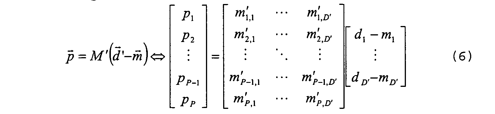
- Alternatively, as shown by following relation (7), it can be seen that the encoding matrix M , the descriptions vector
d and pixels vectorp can be extended to include also translations: vectors are extended with a value which is set to 1 if vectors are normalized; the encoding matrix M has an additional column of coefficients which specify the translation offsets, also it has an additional row of coefficients all set to zero except for the last one which is set to 1 if the encoding matrix M is normalized:
- The decoding matrix can be computed as follows: the reduced matrix M r is extracted from the extended encoding matrix M by extracting the rows corresponding to received descriptions
d '. The last row of the encoding matrix M (related to the last 1 in the description vector) is always taken. Then, as usual, the decoding matrix M' is set equal to the inverse or pseudoinverse of the reduced matrix M r . - Alternatively, the reduced matrix M r can be computed as explained before with reference to equation (2). Then the decoding matrix M' can be extended to compensate for the offsets by adding one column of coefficients, as follows:

- This column of coefficients can be computed by multiplying the usual decoding matrix M' by the negated column vector of offsets m.

- Offsets can be used to implement a sort of "dithering" through the descriptions. In fact, descriptions will often be quantized (and then transmitted in a compressed form). By adding variable offsets to descriptions, dithering is implemented directly on descriptions.
- Offsets can be thus computed by taking into account the quantizazion error of neighboring groups G of descriptions. By using proper offsets, the resulting quantization error will compensate the quantization error of neighboring groups (ideally it will have opposite sign and value).
- Alternatively, offsets can be computed only by considering the spatial position of the group G within the picture PK (i.e. the spatial position of the pixels in that group). This is useful to avoid flickering due to variable dithering in a sequence of pictures.
- It must be noted that the proposed method also can exploit the fact that descriptions may have a limited dynamic. In fact, when descriptions are fed to a standard video encoder, they have to be represented as 8-bits unsigned integers. Therefore dynamic of descriptions will be limited to the interval [0, 255]. The encoding matrix M can be designed to respect this constraint.
- The i-th description d i , where i is an index varying from 1 to D , is generated using the following equation:

- The dynamic, i.e. the maximum and minimum value, of i-th description d i can be easily found.
- The minimum value can be found by computing the sum represented by equation(10) and using the maximum value max( p j) if the encoding matrix M coefficients m i,j are less than zero, the minimum value min(p j ) if the encoding matrix M coefficients m i,j are greater than zero.
- On the opposite the maximum value can be found by computing the sum (10) and using max ( p j ) if the encoding matrix M coefficients m i,j are greater than zero, min(p j ) if the encoding matrix M coefficients m i,j are less than zero. If offsets ( m i #0) are used then they must be added to the computed values.
- Because min( p j ) = 0 and max( p j )= 255, the minimum value is simply the sum of negative coefficients multiplied by 255, while the maximum value is the sum of positive coefficients multiplied by 255. Again, offsets must be added if used, according to the following equations:

- If max ( d i ) >255 or min ( d i ) <0 then description d i will suffer the overload distortion. When the description is out of range, then it is clipped (or saturated). This can be seen as if a suitable constant e is added to the i-th description d i to make it fall in the allowed range. If the i-th description d i >255 then e = d i -255, if d i <0 then e = 0- d i . When decoding d i + e will be used instead of d i .
- The effect of the overload error can be easily computed (see below).
- It is interesting to note also that descriptions may have a limited precision. As already mentioned, when descriptions are fed to a standard video encoder, they have to be represented as 8-bits unsigned integers. There are thus 256 quantization levels in the allowed dynamic range [0, 255]. The distance between two consecutive quantization levels will be 1/255th of the dynamic, i.e. a quantization interval, or quantization step Q , is 1. If the value of the i-th description d i is rounded to the nearest quantization level, then a quantization error e Q will lay in the range: [- Q /2, + Q /2] = [-0.5, +0.5] .
- Depending on the desired compression ratio, the quantization step Q can be greater. In this case, the error range will also be greater. This can be seen as if a suitable constant corresponding to the quantization error e Q is added to the i-th description d i . When decoding d i + e Q will be used instead of d i .
- The effect of the quantization error e Q on the reconstructed pixels can be easily computed.
- The proposed method also comprises a procedure for dealing with error bounds. A general bound can be computed in a straightforward manner. Descriptions are computed by means of the encoding matrix M , according to equation (5), whereas reconstructed pixels are computed by means of the (pseudo-) inverse decoding matrix M' using available descriptions
d ', according to equation (6). - If descriptions are altered by an error e d' on the available descriptions, then reconstructed pixels
p will also be affected by a pixel error e p : - Simplifying, the vector of pixel errors e p can be found, given the vector of errors e d' on the available descriptions:
- The dynamic of errors on reconstructed pixels can also be computed, as it has been done for the dynamic of descriptions.
- The j-th pixel p j , where j is an index ranging from 1 to P , is reconstructed using the following equation:

- If descriptions are affected by errors, then also the j-th reconstructed pixel will be affected by a corresponding pixel error eP
j so it is possible to write:
- Simplifying, the pixel error e pj on the j-th reconstructed pixel p j can be computed, given errors on the available descriptions, according to the following:

- The dynamic pixel error e p,j on the j-th reconstructed pixel p j can be easily found. The minimum value can be found by computing the sum expressed by equation (16) and using max ( e d , ,i ) if m' i,j <0, min (e d',i ) if m' i,j >0. On the opposite the maximum value can be found by computing the sum of equation (16) and using max (e d , ,j ) if m' i,j >0, min (e d',i ) if m' i,j <0.
- It must be noted that often the following equality is verified:
- Hence, for the error on the j-th reconstructed pixel, the minimum value is simply the sum of negated absolute values of coefficients multiplied by the quantization error e Q , while the maximum value is the sum of absolute values of coefficients multiplied by the quantization error e Q .

- Errors on reconstructed pixels may be bounded in the pixel domain, but also they can be characterized in the frequency domain, since they are expressed through the matrix coefficients. This is especially useful when evaluating the perceptual meaning of such errors by taking into account the Human Visual System (HVS) characteristics.
- Now a procedure for designing an equivalent encoding filter bank will be detailed.
- An equivalent structure using filter banks can be devised both for multiple descriptions encoding and multiple descriptions decoding.
- The equivalent filter bank is computed as follows. As many parallel filters F1...FD as the number of descriptions D are provided, as shown in fig. 4. Each filter F1 has a two-dimensional set of coefficient whose value is specified in the corresponding row of the encoding matrix M and whose position is specified by the position of the corresponding pixel in the pixel vector p. The output of each filter F1...FD is downsampled in a suitable downsampling module DS so that surviving output values, a filtered picture FPK, from the downsampling module DS match the values computed when applying the encoding matrix M to the specified group of pixels G. Obviously, discarded output values need not to be computed.
- In other words, the encoding matrix M has D rows and P columns, the pixel vector
p has P pixels. Therefore there will be D parallel filters F1..FD. The generic coefficient m i,j of the encoding matrix M is one of the coefficients of the i-th filter. Its two-dimensional spatial position is specified by the position of the j-th pixel within the group of pixels G to which the encoding matrix M is to be applied. - It must be appreciated that the filter bank structure shown in figure 4 is more flexible than a spatial/temporal polyphase downsampling structure. With the latter, one can only use one pre-processing filter. This means that all description will suffer the same information loss. With the filter bank structure, each description has its own pre-processing filter. This means that perfect reconstruction is possible as long as the information loss suffered in a given description is compensated by analogous information available in other descriptions.
- For what concerns the multiple description procedure, an equivalent decoding filter bank can also be obtained.
- The equivalent filter bank is useful to study the two-dimensional spectrum of reconstructed pixels given the two-dimensional spectrum of incoming descriptions. In this way it is possible to evaluate the visibility of quantization errors introduced by video encoders.
- Multiple Description decoding can be tuned so that the visibility of quantization errors is not enhanced. Once the MD decoding part has been optimized, the MD encoding part can be derived. In turn, once the MD encoding part has been derived, video encoders can be tuned.
- The equivalent filter bank for implementing the decoding matrix M' is computed as follows: as many parallel filters F' 1...F' D as the number D of descriptions are provided. Each filter input is upsampled in suitable uplsampling module UP by zeros insertion to compensate the downsampling performed at the encoder.
- Each filter has a two-dimensional set of coefficients whose value is specified in the corresponding row of the transposed decoding matrix M' and whose position is specified by the position of the corresponding pixel in the reconstructed pixel vector.
- The transposed decoding matrix M' has D rows and P columns, the reconstructed pixel vector has P pixels. Therefore there will be D parallel filters F'1...F'D. Let m' i,j be an element of the transposed decoding matrix M': this is one of the coefficients of the i-th filter. Its two-dimensional spatial position is specified by the position of the j-th pixel within the group of reconstructed pixels which the transposed decoding matrix M' generates.
- The output of each filter F' 1...F'D is summed at a given pixel position so that all contributions from all available descriptions
d are used. - In figure 5a is shown a possible embodiment, where a priori statistic is enforced using a suitable pre-processing filter, placed in the
pre-processing block 100, that is a low-pass pre-processing filter can be used. - A picture PK of a video sequence in the input signal I, having L columns and N rows, is sent to a bank of filters 200, disposed in parallel, comprising a first filter h0 and a second filter h1, that generate two descriptions by separating even and odd rows of the original video sequence. The corresponding filter impulses responses are h 0 (n)=δ n and h 1 (n)=δ n+1 . An additional filter h2 produces an additional description, by a low-pass filtering operation in the column direction. Such an additional filter belongs to the family of Daubechies filters, that are orthogonal to their factor two translations. Each of the descriptions generated in the bank of filters 200 passes through a
corresponding subsampling block 202, that performs a subsampling by a factor two, thus producing subsampled descriptions having L x N/2 size. The three subsampled descriptions are then coded through correspondingindependent encoders 102, of the H.264/AVC type, that divide the input frame, i.e. the subsampled description, into slices made from macroblocks organized into rows, sending each slice on the network like a single packet. - In figure 5b the receiver side is shown, where video streams are independently processed by
decoders 104, that are H. 264/AVC synchronised decoders.Such decoders 104 are connected to a restoring block R, which recovers channel errors. Restoring block R is similar to block 108 shown in figure 1, however in the embodiment of figure 1 error correction is performed in the pixel domain, whereas the restoring block R operates in the multiple description domain, before such descriptions are translated into pixels by the following blocks. - In the case of unrecoverable errors, missing regions in lost descriptions are reconstructed, using bilinear interpolation, from the received descriptions.
- The recovered subframes, having LxN/2 size, are thus outputted by the restoring block R and fed, after passing through a
corresponding upsampling block 203, that performs an upsampling by a factor two, to a decoding bank offilter 204, comprising filters g0, g1 and g2, that output the original full size sequences that are summed in asuitable sum block 205 to obtain picture PK. - The proposed method also includes a luma processing procedure. As it well known, video sequences can have interlaced luma: this means that each picture or frame is subdivided in two part. The first part is made of all the odd lines and is called the top or odd field. The second part is made of all the remaining even lines and is called the bottom or even field. The two fields are acquired one after the other, hence the field rate is twice the frame rate.
- Interlaced video is used to match the HVS (Human Visual System) characteristics. When there is no motion, the eye will see an high-definition still picture refreshed at the frame-rate. When there is motion, the eye will se a low-definition moving picture refreshed at the field-rate (which is twice the frame-rate). This is precisely what the eye wants to see.
- If this is taken into account, then fields are split prior multiple description encoding. Then descriptions from both fields are mixed so that each description is "interlaced" in the sense that it contains information of both fields.
- If this is not taken into account, fields are not split prior multiple description encoding. The frame is processed as a whole. This is called "direct luma processing".
- In case the "direct luma processing" is used, it is preferable that each description contain information of only one field, either the top or the bottom. This is because standard video encoders can be easily tuned for progressive subsequences. Direct luma processing can be obtained by performed by demultiplexing for interlaced video prior encoding matrix multiplication and by field multiplexing after encoding matrix multiplication.
- In other words, it is possible, by choosing a suitable polyphase downsampling scheme, to generate descriptions that contains informations pertaining only one field. This allows for taking in account the interlaced structure of the picture. In order to do so, it is sufficiente that such downsampling scheme includes a vertical downsampling on the rows suitable for separating even rows from the odd rows. The final result is that the descriptions, containing information about only one field, are coded more efficiently.
- The indirect processing, on the other hand takes in account the interlaced structure of the picture, separating the two interlaced fields and creating two descriptions for the two fields that are then merged in a single set of descriptions, containing information about both the two fields. The encoding of such a single merged set of descriptions is more heavy from a computational point of view and thus less efficient.
- Alternatively, descriptions from both fields have to be mixed in an optimal way so that they match as closely as possible the statistic of an interlaced video. This is because standard video encoders can also be tuned for interlaced video.
- In conclusion, the "direct luma processing" is preferable. In fact, it is difficult to mix descriptions from both fields in an optimal way, while it is relatively easy to have descriptions that contain information of only one field.
- The proposed method also includes a chroma processing procedure.
- Video sequence usually have subsampled chroma:
- this means that each picture has subsampled chroma signals. Subsampling can be either horizontal (as in 4:2:2 format) or both horizontal and vertical (as in 4:2:0 formats).
-
- Subsampled chroma is used to reduce the amount of the information by discarding what cannot be seen because of the HVS characteristics. The eye is most sensitive to the luma, then luma must be at full resolution while the chroma can be downsampled (2:1 or even 4:1).
- If this is taken into account, then the chroma is upsampled to full resolution (4:4:4) prior multiple description encoding. Then chroma descriptions are downsampled in a suitable way, so that in each description the ratio of chroma information with respect to luma is the same as before (i.e. ½ or ¼).
- If this is not taken into account, chroma is not upsampled to 4:4:4 prior multiple description encoding. The subsampled chroma is processed as is. This is called "direct chroma processing".
- In case of chroma upsampling and downsampling, fields must be processed separately in order to avoid color artifacts that may arise due to the motion of objects.
- In case the "direct chroma processing" is used, it is important to ensure that each description has chroma information closely related (spatially and temporally) to the luma information. This is because it is desirable to keep the independent decoding property of each description.
- As an example: if one description holds luma information from one field and chroma information from the other field, color artifacts will be likely in case there is motion of objects because of the temporal distance between fields. This means that the luma information will be usable only if another description is available, specifically the one with the correct chroma information.
- It can be observed that it is more important to keep the temporal relation among luma and chroma sample rather than the spatial relation. This is because color artifacts due to small offsets among the luma and chroma sampling grid will not be visible in most cases, because in many chroma formats luma and chroma samples are not co-sited).
- In conclusion, the "direct chroma processing" is preferable. In fact, upsampling and downsampling do blur the original chroma information and they are also resource demanding. On the opposite, it is relatively easy to keep the spatial relation among luma and chroma samples, particularly when "direct luma processing" has been used.
- The proposed method also includes a procedure for compressing descriptions.
- Descriptions may be compressed using state-of-the-art lossless or lossy techniques prior transmission.
- It is even possible to use standard video encoders which are usually made of a prediction (e.g. motion estimation and compensation), transform (2D 8x8 DCT or multi-level DWT), adaptive scalar/vector quantization and entropy coding of quantized coefficients and auxiliary prediction signals (e.g. motion vectors).
- The sequence to be compressed is made up by juxtaposition of descriptions. In order to preserve the statistic of data exploited by standard video encoders, it is preferable to juxtapose descriptions of neighboring group of pixels generated using the same coefficients. Preferably, the spatial position of the juxtaposed description will be related to the position of the group of pixels from which it has been computed.
- By way of example, the picture PK of figure 2 can be partitioned into many non-overlapping groups G of the same size and shape. Thus the same encoding matrix M can be used for all these groups G to generate description vectors d. Each element in all description vectors
d will form a different sequence to be compressed: the first element from all description vectorsd will form the picture for the first sequence, the second will form the second sequence, and so on. In each sequence, the position of an element within the picture will be chosen according to the position of the group of pixels G which has generated the element. - After compression, encoded descriptions (bitstreams) can be grouped as desired. Groups of encoded descriptions can then be transmitted, in particular over one channel using proper channel sharing policies, (e.g. interleaving). Alternatively and preferably, if more than one channel is available, groups of compressed descriptions can be transmitted exploiting channel diversity.
- The proposed method and apparatus show several advantages.
- Considering for instance comparison of the proposed method and systems with multiple description coding methods involving QFE matrix multiplication:
- QFE matrix is combined with quantization (for encoding) and dequantization (for decoding) while in the proposed method matrix multiplication is combined with downsampling (for encoding) and upsampling (for decoding). Nevertheless, as shown previously quantization may be included in the proposed method as well;
- QFE matrix generates only SNR multiple descriptions while the proposed method is mainly tailored for Spatial and/or Temporal multiple descriptions. SNR descriptions may also be generated by using the proposed method as it has been explained previously with reference to dithered descriptions;
- in QFE matrix multiplication the data to be encoded are assumed to be independent, if this is not the case, the Karhunen-Loeve is eventually used to decorrelate the data; next a correlating transform is applied with the matrix multiplication. This correlation is exploited to estimate lost data. On the opposite, in the proposed method, the dependence among data is a desirable property and it is preserved by the matrix multiplication. Particularly, spatial and temporal correlation of the data corresponding to groups of pixels (a priori statistic) are preserved. Alternatively spatial and temporal correlation is computed from received data (a posteriori statistic). Both are used to reconstruct lost data as previously detailed in describing the coupled concealment procedures and decoupled concealment procedures.
- Another advantage of the proposed method lies in that it is specifically suited to generate descriptions which have a visual meaning. Generated subsequences can be compressed using standard state-of-the-art video codecs. This explains why it is worth preserving spatial and temporal correlation of the original data: standards codecs are tuned to exploit this kind of correlation in order to achieve compression. As a consequence, it must be noticed that the proposed method withstand lossy compression. On the opposite, descriptions generated by QFE have poor visual meaning. Because of this, compressing subsequences is a very difficult task in the QFE framework. Specific procedures are required and lossless techniques have to be used.
- The proposed method allows for easy implementation through equivalent banks of filters, that are useful to study the two dimensions spectrum of the generated descriptions. Standard video encoders, which may be used to compress generated description, are tuned to discard high-frequency parts of the spectrum which are believed not to be perceivable. The compression is then lossy but visually lossless.
- Multiple descriptions can be tuned to ease the compression task of standard video encoders. Alternatively, video encoders can be tuned to match the statistic of generated descriptions. As an example: the quantization matrix for transformed coefficients and the zig-zag scan path can be chosen.
- Of course, without prejudice to the underlying principle of the invention, the details and embodiments may vary, also significantly, with respect to what has been described and shown by way of example only, without departing from the scope of the invention as defined by the annexed claims.
- It must be noted that the proposed method, presenting an increased error resiliency, may render superfluos channel coding. However, the proposed method can substitute channel coding as well.
- Multiple descriptions coding shows at least two advantages with respect to know channel coding techniques based on error correction codes:
- error correction codes are decoded only if errors are under a certain threshold, whereas multiple descriptions coding always decodes, although sometimes with a lower quality;
- by using error correction codes the situation of ghaving errors are under a certain threshold is equivalent to absence of errors, whereas multiple descriptions coding can exploit redundancy to reduce quality loss due to source coding.
- Reed-Solomon codes for instance, starting from P data packets, generate D packets, with D greater than P . Such D packets contain the P data packets and redundant packets. Decoding is ensured if at least P packets are received.
- The proposed method can operate in the same way.
- The proposed method starts from a number P of pixels and generate D descriptions. D can also be greater or equal than P . Decoding is ensured if at least P descriptions are received.
- Thus, for instance, instead of using a channel code having a 3/2 redundancy, a multiple descriptions coding scheme can be used that generate two descriptions and add a third description.
- As another example: instead of using a channel code with redundancy 5/4, a multiple descriptions coding scheme can be used that generate four descriptions and add a fifth description.
Claims (44)
- A method for encoding video signals, including the operations of generating a multiple descriptions vector (
d ) associated to a pixel values vector (p )of said video signals, wherein said operation of generating a multiple descriptions vector (d ') includes the steps of obtaining said pixel values vector (p ) by selecting a group (G) of pixels in a picture (PK) of said video signal and applying an encoding matrix (M) to said pixel values vector (p ). - The method of claim 1, characterized in that said encoding matrix (M) comprises respective coefficients (m i,j ) that are representative of respective encoding equations systems, and that includes the step of implementing said encoding matrix (M) through respective banks of filters (200) having said respective coefficients (m i,j ) as the filter coefficients.
- The method of either of claims 1 or 2, characterized in that it further includes subdividing said encoding matrix (M) in a plurality of sub-matrixes (M i ) and associating through each of said sub-matrixes (M i ) a subset of pixels in said group (G) of pixels to a subset of descriptions (D i ).
- The method of claim 3, characterized in that said subdividing includes applying permutations for to obtain a block diagonal structure on said encoding matrix (M).
- The method of any of the preceding claims, characterized in that said step of selecting a group (G) of pixels in a picture (PK) of said video signal includes selecting groups of pixels (G1) comprising pixels adjacent to each other.
- The method of any of the preceding claims, characterized in that said step of selecting a group (G) of pixels in a picture (PK) of said video signal includes selecting groups of pixels (G2) partially overlapping.
- The method of any of the preceding claims, characterized in that it further includes the step of adding coefficients to said encoding matrix that are based on the statistics of groups (G).
- The method of claim 7, characterized in that said step of adding coefficients is used for implementing a coupled concealment procedure.
- The method of claim 7, characterized in that said step of adding coefficients is used for implementing a decoupled concealment procedure.
- The method of any of the preceding claims, characterized in that said operation of generating a multiple descriptions vector (
d ) includes performing a translation of said multiple descriptions vector (d ). - The method of claim 10, characterized in that said step of performing a translation includes adding a corresponding offset vector (
m )to said encoding matrix (M). - The method of claim 10, characterized in that said step of performing a translation includes extending said encoding matrix (M), said descriptions vector (
d )and said pixel values vector( p ). - The method of any of claims 10 to 12, characterized in that said translation of said multiple descriptions vector is performed by adding variable offsets to descriptions in order to implement a dithering directly on descriptions.
- The method of any of the preceding claims, characterized in that it includes a luma processing procedure.
- The method of claim 14, characterized in that said luma processing procedure includes demultiplexing for interlaced video prior applying said encoding matrix ( M ) and by field multiplexing after applying said encoding matrix ( M ).
- The method of any of the preceding claims, characterized in that it includes a chroma processing procedure.
- The method of claim 16, characterized in that said luma processing procedure includes performing a chroma interpolation step, and a decimation step prior applying said encoding matrix (M).
- The method of any of the preceding claims, characterized in that said operation of generating a multiple descriptions vector (
d )includes adding descriptions for a channel coding operation. - The method of any of the preceding claims, characterized in that said multiple descriptions vector (
d )contains spatial and/or temporal multiple descriptions. - The method of any of claims from 1 to 18, characterized in that said multiple descriptions vector (
d ) contains SNR multiple descriptions. - The method of any of the previous claims, characterized in that includes the step of subjecting said video signals to a compression procedure (102).
- A method for decoding video signals encoded by means of a multiple descriptions vector (
d )based on an encoding matrix ( M ) associated to a pixel values vector (p) of said video signals, the method including the operations of decoding an available descriptions vector (d ')for reconstructing said pixel values vector (p ),wherein said decoding operation includes the step of applying a decoding matrix (M') to said available descriptions vector (d ')to obtain said pixel values vector (p ),said decoding matrix ( M' ) being in an inversion relationship with said encoding matrix ( M ). - The method of claim 22, characterized in that said decoding matrix ( M' ) comprises respective coefficients (m' i,j ) that are representative of respective decoding equations systems, and that includes the step of implementing said decoding matrix ( M' ) through respective banks of filters (204) having said respective coefficients (m' i,j ) as the filter coefficients.
- The method of either of claims 22 or 23, characterized in that said decoding operation includes the following steps:taking rows from the encoding matrix ( M ) corresponding to said available descriptions vector (
d ')to form a reduced matrix ( M r ) ;obtaining said decoding matrix ( M' ) by computing the inverse (inv (M r )) of the reduced matrix (M r ) or the pseudo-inverse matrix (pinv (M r )) of said reduced matrix ( M r ) ;reconstructing said pixels vector (p ) by a single matrix multiplication between said pseudo-inverse matrix (pinv (M r )) or inverse matrix (inv (M r )) and the column vector of available descriptions (d '). - The method of claim 24, characterized in that, in case said decoding matrix (M') represents an over-determined system, it includes the step of reconstructing said pixels vector (
p ) by one of:using a minimum least square procedure, andcomputing a decoding subset matrix (M") from said decoding matrix (M') by deleting columns corresponding to unused descriptions. - The method of any of claims 22 to 25, characterized in that it further includes the step of adding coefficients to said decoding matrix that are based on the statistics of groups (G).
- The method of any of claims 22 to 26, in combination with the coding method of any of claims 1 to 21, characterized in that, in case said decoding matrix ( M' ) represents an under-determined system, it includes the step of applying a permutation to said encoding matrix ( M ) to obtain a block diagonal structure and computing a subset matrix ( M" ) from the decoding matrix ( M' ) by deleting rows corresponding to unreconstructed pixels.
- The method of any of claims 22 to 26, in combination with the coding method of any of claims 1 to 21, characterized in that in case said decoding matrix ( M' ) represents an under-determined system it includes said step of adding coefficients to the encoding matrix ( M ) and/or the decoding matrix ( M' ), such added coefficients being based respectively on a priori information about the statistics of groups (G) or on a posteriori information about the statistics of groups (G).
- The method of any of claims 22 to 28, characterized in that said multiple descriptions vector (
d ) contains spatial and/or temporal multiple descriptions. - The method of any of claims from 22 to 28, characterized in that said multiple descriptions vector (
d ) contains SNR multiple descriptions. - The method of any of claims 22 to 30, characterized in that includes applying a decompression procedure (104) to said signals decoded.
- A system for encoding video signals comprising a module (100) for generating a multiple descriptions vector (
d ) associated to a pixel values vector (p ) of said video signals, the system being configured for implementing the method of any of claims 1 to 21. - The system of claim 32, characterized in that said equivalent filter bank (200) comprises as many parallel filters (F1...FD; h0, h1, h2) as the number of descriptions (D) in the descriptions vector (
d ). - The system of claim 33, characterized in that each of said parallel filters ( (F1...FD; h0, h1, h2) has a two-dimensional set of coefficient whose value is specified in a corresponding row of the encoding matrix (M) and whose position is specified by the position of the corresponding pixel in the pixel values vector (
p ). - The system of claim 33, characterized in that the output of each of said parallel filters ((F1...FD; h0, h1, h2) is downsampled in a suitable downsampling module (DS; 202) to produce a filtered picture (FPK).
- The system of any of claims 32 to 35, characterized in that comprises standard video encoders (102).
- The system of claim 36, characterized in that said standard video encoders (102) are configured for compressing the generated description and discarding high-frequency parts of the spectrum which are considered not to be perceivable.
- A system for decoding video signals comprising a module (108) for decoding an available descriptions vector (
d ') for reconstructing a pixel values vector (p ), the system being configured for implementing the method of any of claims 22 to 31. - The system of claim 38, characterized in that said equivalent filter bank (204) for implementing the decoding matrix (M') comprises as many parallel filters (F'1...F'D; g0, g1, g2) as the number of descriptions (D) in the descriptions vector (
d ). - The system of claim 38, characterized in that each of said parallel filters (F'1... F'D; g0, g1, g2) has a two-dimensional set of coefficient (m' ij ) whose value is specified in the corresponding row of the transposed decoding matrix ( M' ) and whose position is specified by the position of the corresponding pixel in the reconstructed pixel values vector (
p ). - The system of claim 40, characterized in that the input of each of said parallel filters (F'1... F'D; g0, g1, g2) is upsampled by a suitable upsampling module (UP; 203) by zeros insertion.
- The system of any of claims 38 to 41, characterized in that it comprises a restoration module (R) suitable for recovering channel errors.
- The system of any of claims from 38 to 42, characterized in that it comprises standard video decoders (104).
- A computer program product loadable in the memory of at least one computer and including software code portions for performing at least one of the method of claims 1 to 21 and the method of any of claims 22 to 31 when the product is run on a computer.
Priority Applications (2)
| Application Number | Priority Date | Filing Date | Title |
|---|---|---|---|
| EP04006490A EP1578134A1 (en) | 2004-03-18 | 2004-03-18 | Methods and systems for encoding/decoding signals, and computer program product therefor |
| US11/084,531 US7961790B2 (en) | 2004-03-18 | 2005-03-18 | Method for encoding/decoding signals with multiple descriptions vector and matrix |
Applications Claiming Priority (1)
| Application Number | Priority Date | Filing Date | Title |
|---|---|---|---|
| EP04006490A EP1578134A1 (en) | 2004-03-18 | 2004-03-18 | Methods and systems for encoding/decoding signals, and computer program product therefor |
Publications (1)
| Publication Number | Publication Date |
|---|---|
| EP1578134A1 true EP1578134A1 (en) | 2005-09-21 |
Family
ID=34833633
Family Applications (1)
| Application Number | Title | Priority Date | Filing Date |
|---|---|---|---|
| EP04006490A Withdrawn EP1578134A1 (en) | 2004-03-18 | 2004-03-18 | Methods and systems for encoding/decoding signals, and computer program product therefor |
Country Status (2)
| Country | Link |
|---|---|
| US (1) | US7961790B2 (en) |
| EP (1) | EP1578134A1 (en) |
Cited By (4)
| Publication number | Priority date | Publication date | Assignee | Title |
|---|---|---|---|---|
| WO2009131830A1 (en) * | 2008-04-24 | 2009-10-29 | Motorola, Inc. | Method and apparatus for encoding and decoding video |
| US7991055B2 (en) | 2004-09-16 | 2011-08-02 | Stmicroelectronics S.R.L. | Method and system for multiple description coding and computer program product therefor |
| US8432963B2 (en) | 2004-07-06 | 2013-04-30 | Stmicroelectronics S.R.L. | Method for encoding signals, related system and program product |
| TWI449431B (en) * | 2006-10-16 | 2014-08-11 | Nokia Corp | Method,apparatus and computer program products for using parallelly decodable slices for multi-view video coding |
Families Citing this family (23)
| Publication number | Priority date | Publication date | Assignee | Title |
|---|---|---|---|---|
| EP1605400A1 (en) * | 2004-06-11 | 2005-12-14 | STMicroelectronics S.r.l. | Processing pipeline of pixel data of a color image acquired by a digital sensor |
| US20070160134A1 (en) * | 2006-01-10 | 2007-07-12 | Segall Christopher A | Methods and Systems for Filter Characterization |
| KR100827093B1 (en) * | 2006-10-13 | 2008-05-02 | 삼성전자주식회사 | Method for video encoding and apparatus for the same |
| US8121195B2 (en) * | 2006-11-30 | 2012-02-21 | Lsi Corporation | Memory reduced H264/MPEG-4 AVC codec |
| US20100271981A1 (en) * | 2007-12-10 | 2010-10-28 | Wei Zhao | Method and system f0r data streaming |
| WO2009120830A1 (en) * | 2008-03-27 | 2009-10-01 | Tufts University | Methods and apparatus for visual sub-band decomposition of signals |
| US20110249742A1 (en) * | 2010-04-07 | 2011-10-13 | Apple Inc. | Coupled video pre-processor and codec including reference picture filter that minimizes coding expense during pre-processing mode transitions |
| US8644376B2 (en) * | 2010-09-30 | 2014-02-04 | Alcatel Lucent | Apparatus and method for generating compressive measurements of video using spatial and temporal integration |
| US9319578B2 (en) | 2012-10-24 | 2016-04-19 | Alcatel Lucent | Resolution and focus enhancement |
| US9344736B2 (en) | 2010-09-30 | 2016-05-17 | Alcatel Lucent | Systems and methods for compressive sense imaging |
| US9634690B2 (en) * | 2010-09-30 | 2017-04-25 | Alcatel Lucent | Method and apparatus for arbitrary resolution video coding using compressive sampling measurements |
| US8929456B2 (en) * | 2010-09-30 | 2015-01-06 | Alcatel Lucent | Video coding using compressive measurements |
| US9020029B2 (en) * | 2011-01-20 | 2015-04-28 | Alcatel Lucent | Arbitrary precision multiple description coding |
| KR101215152B1 (en) | 2011-04-21 | 2012-12-24 | 한양대학교 산학협력단 | Video encoding/decoding method and apparatus using prediction based on in-loop filtering |
| US9398310B2 (en) | 2011-07-14 | 2016-07-19 | Alcatel Lucent | Method and apparatus for super-resolution video coding using compressive sampling measurements |
| EP2777287A2 (en) | 2011-11-07 | 2014-09-17 | VID SCALE, Inc. | Video and data processing using even-odd integer transforms background |
| US9491459B2 (en) * | 2012-09-27 | 2016-11-08 | Qualcomm Incorporated | Base layer merge and AMVP modes for video coding |
| US20140168040A1 (en) * | 2012-12-17 | 2014-06-19 | Qualcomm Mems Technologies, Inc. | Motion compensated video halftoning |
| US9563806B2 (en) | 2013-12-20 | 2017-02-07 | Alcatel Lucent | Methods and apparatuses for detecting anomalies using transform based compressed sensing matrices |
| US9600899B2 (en) | 2013-12-20 | 2017-03-21 | Alcatel Lucent | Methods and apparatuses for detecting anomalies in the compressed sensing domain |
| WO2015191068A1 (en) * | 2014-06-12 | 2015-12-17 | Spinella Ip Holdings, Inc. | Transmission and restoration of decimated image data |
| US9894324B2 (en) | 2014-07-15 | 2018-02-13 | Alcatel-Lucent Usa Inc. | Method and system for modifying compressive sensing block sizes for video monitoring using distance information |
| CN112217820B (en) * | 2020-09-27 | 2022-08-09 | 伍仁勇 | Network transmission method and system, and local coding core generation method and system |
Family Cites Families (9)
| Publication number | Priority date | Publication date | Assignee | Title |
|---|---|---|---|---|
| US5280540A (en) * | 1991-10-09 | 1994-01-18 | Bell Communications Research, Inc. | Video teleconferencing system employing aspect ratio transformation |
| US6012159A (en) * | 1996-01-17 | 2000-01-04 | Kencast, Inc. | Method and system for error-free data transfer |
| JP3207739B2 (en) * | 1996-01-19 | 2001-09-10 | 松下電器産業株式会社 | Image playback device |
| US6345125B2 (en) | 1998-02-25 | 2002-02-05 | Lucent Technologies Inc. | Multiple description transform coding using optimal transforms of arbitrary dimension |
| US7110953B1 (en) | 2000-06-02 | 2006-09-19 | Agere Systems Inc. | Perceptual coding of audio signals using separated irrelevancy reduction and redundancy reduction |
| US7103669B2 (en) | 2001-02-16 | 2006-09-05 | Hewlett-Packard Development Company, L.P. | Video communication method and system employing multiple state encoding and path diversity |
| US7158591B2 (en) | 2001-05-09 | 2007-01-02 | Signum Concept, Inc. | Recursive resampling digital filter structure for demodulating 3G wireless signals |
| JP4506039B2 (en) | 2001-06-15 | 2010-07-21 | ソニー株式会社 | Encoding apparatus and method, decoding apparatus and method, and encoding program and decoding program |
| US7262806B2 (en) * | 2001-11-21 | 2007-08-28 | Broadcom Corporation | System and method for aligned compression of interlaced video |
-
2004
- 2004-03-18 EP EP04006490A patent/EP1578134A1/en not_active Withdrawn
-
2005
- 2005-03-18 US US11/084,531 patent/US7961790B2/en active Active
Non-Patent Citations (3)
| Title |
|---|
| KHANSARI M R K ET AL: "SUBBAND DECOMPOSITION OF SIGNALS WITH GENERALIZED SAMPLING", IEEE TRANSACTIONS ON SIGNAL PROCESSING, IEEE, INC. NEW YORK, US, vol. 41, no. 12, 1 December 1993 (1993-12-01), pages 3365 - 3375, XP000426653, ISSN: 1053-587X * |
| LEE Y-C ET AL: "An integrated application of multiple description transform coding and error concealment for error-resilient video streaming", SIGNAL PROCESSING. IMAGE COMMUNICATION, ELSEVIER SCIENCE PUBLISHERS, AMSTERDAM, NL, vol. 18, no. 10, November 2003 (2003-11-01), pages 957 - 970, XP004472767, ISSN: 0923-5965 * |
| TSUHAN CHEN ET AL: "RECENT DEVELOPMENTS IN MULTIDIMENSIONAL MULTIRATE SYSTEMS", IEEE TRANSACTIONS ON CIRCUITS AND SYSTEMS FOR VIDEO TECHNOLOGY, IEEE INC. NEW YORK, US, vol. 3, no. 2, 1 April 1993 (1993-04-01), pages 116 - 137, XP000367177, ISSN: 1051-8215 * |
Cited By (7)
| Publication number | Priority date | Publication date | Assignee | Title |
|---|---|---|---|---|
| US8432963B2 (en) | 2004-07-06 | 2013-04-30 | Stmicroelectronics S.R.L. | Method for encoding signals, related system and program product |
| US7991055B2 (en) | 2004-09-16 | 2011-08-02 | Stmicroelectronics S.R.L. | Method and system for multiple description coding and computer program product therefor |
| TWI449431B (en) * | 2006-10-16 | 2014-08-11 | Nokia Corp | Method,apparatus and computer program products for using parallelly decodable slices for multi-view video coding |
| WO2009131830A1 (en) * | 2008-04-24 | 2009-10-29 | Motorola, Inc. | Method and apparatus for encoding and decoding video |
| US8249142B2 (en) | 2008-04-24 | 2012-08-21 | Motorola Mobility Llc | Method and apparatus for encoding and decoding video using redundant encoding and decoding techniques |
| KR101249652B1 (en) * | 2008-04-24 | 2013-04-01 | 모토로라 모빌리티 엘엘씨 | Method and apparatus for encoding and decoding video |
| CN102067599B (en) * | 2008-04-24 | 2014-06-11 | 摩托罗拉移动公司 | Method and apparatus for encoding and decoding video |
Also Published As
| Publication number | Publication date |
|---|---|
| US20050207498A1 (en) | 2005-09-22 |
| US7961790B2 (en) | 2011-06-14 |
Similar Documents
| Publication | Publication Date | Title |
|---|---|---|
| US7961790B2 (en) | Method for encoding/decoding signals with multiple descriptions vector and matrix | |
| Karlsson et al. | Three dimensional sub-band coding of video | |
| KR101183304B1 (en) | Spatial scalability in 3d sub-band decoding of sdmctf-encoded video | |
| KR101176650B1 (en) | Embedded base layer codec for 3d sub-band coding | |
| US20050207497A1 (en) | Encoding/decoding methods and systems, computer program products therefor | |
| MX2013003868A (en) | Method and apparatus for feature based video coding. | |
| US9992503B2 (en) | Scalable video coding with enhanced base layer | |
| MX2013003871A (en) | Method and apparatus for spatial scalability for hevc. | |
| EP2008459A1 (en) | Video coding method and apparatus supporting independent parsing | |
| US20060146937A1 (en) | Three-dimensional wavelet video coding using motion-compensated temporal filtering on overcomplete wavelet expansions | |
| US8391358B2 (en) | Methods and system for encoding/decoding signals including scrambling spectral representation and downsampling | |
| US20060159173A1 (en) | Video coding in an overcomplete wavelet domain | |
| US6445823B1 (en) | Image compression | |
| US20020186772A1 (en) | Wavelet domain motion compensation system | |
| KR19990013991A (en) | Image compression | |
| Tillier et al. | A motion-compensated overcomplete temporal decomposition for multiple description scalable video coding | |
| JP2004266794A (en) | Multi-resolution video coding and decoding | |
| Apostolopoulos et al. | Video compression for digital advanced television systems | |
| Atta et al. | An efficient layered video codec based on DCT pyramid | |
| Apostolopoulos | Video compression | |
| Lopez et al. | Fully scalable video coding with packed stream | |
| EP0848557A2 (en) | Subband image encoding method | |
| Monta | Signal processing for high-definition television | |
| Houlding | Pyramid coding for image and video compression | |
| Lawai | Scalable coding of HDTV pictures using the MPEG coder |
Legal Events
| Date | Code | Title | Description |
|---|---|---|---|
| PUAI | Public reference made under article 153(3) epc to a published international application that has entered the european phase |
Free format text: ORIGINAL CODE: 0009012 |
|
| AK | Designated contracting states |
Kind code of ref document: A1 Designated state(s): AT BE BG CH CY CZ DE DK EE ES FI FR GB GR HU IE IT LI LU MC NL PL PT RO SE SI SK TR |
|
| AX | Request for extension of the european patent |
Extension state: AL LT LV MK |
|
| 17P | Request for examination filed |
Effective date: 20051123 |
|
| AKX | Designation fees paid |
Designated state(s): DE FR GB IT |
|
| STAA | Information on the status of an ep patent application or granted ep patent |
Free format text: STATUS: THE APPLICATION HAS BEEN WITHDRAWN |
|
| 18W | Application withdrawn |
Effective date: 20070816 |