EP1579381B1 - Jamming device against rfid smart tag systems - Google Patents
Jamming device against rfid smart tag systems Download PDFInfo
- Publication number
- EP1579381B1 EP1579381B1 EP03811998A EP03811998A EP1579381B1 EP 1579381 B1 EP1579381 B1 EP 1579381B1 EP 03811998 A EP03811998 A EP 03811998A EP 03811998 A EP03811998 A EP 03811998A EP 1579381 B1 EP1579381 B1 EP 1579381B1
- Authority
- EP
- European Patent Office
- Prior art keywords
- rfid
- smart
- scanner
- jamming
- smart tag
- Prior art date
- Legal status (The legal status is an assumption and is not a legal conclusion. Google has not performed a legal analysis and makes no representation as to the accuracy of the status listed.)
- Expired - Fee Related
Links
Images
Classifications
-
- G—PHYSICS
- G06—COMPUTING; CALCULATING OR COUNTING
- G06K—GRAPHICAL DATA READING; PRESENTATION OF DATA; RECORD CARRIERS; HANDLING RECORD CARRIERS
- G06K19/00—Record carriers for use with machines and with at least a part designed to carry digital markings
- G06K19/06—Record carriers for use with machines and with at least a part designed to carry digital markings characterised by the kind of the digital marking, e.g. shape, nature, code
- G06K19/067—Record carriers with conductive marks, printed circuits or semiconductor circuit elements, e.g. credit or identity cards also with resonating or responding marks without active components
- G06K19/07—Record carriers with conductive marks, printed circuits or semiconductor circuit elements, e.g. credit or identity cards also with resonating or responding marks without active components with integrated circuit chips
- G06K19/073—Special arrangements for circuits, e.g. for protecting identification code in memory
-
- H—ELECTRICITY
- H04—ELECTRIC COMMUNICATION TECHNIQUE
- H04K—SECRET COMMUNICATION; JAMMING OF COMMUNICATION
- H04K3/00—Jamming of communication; Counter-measures
- H04K3/80—Jamming or countermeasure characterized by its function
- H04K3/82—Jamming or countermeasure characterized by its function related to preventing surveillance, interception or detection
- H04K3/825—Jamming or countermeasure characterized by its function related to preventing surveillance, interception or detection by jamming
-
- G—PHYSICS
- G06—COMPUTING; CALCULATING OR COUNTING
- G06K—GRAPHICAL DATA READING; PRESENTATION OF DATA; RECORD CARRIERS; HANDLING RECORD CARRIERS
- G06K19/00—Record carriers for use with machines and with at least a part designed to carry digital markings
- G06K19/06—Record carriers for use with machines and with at least a part designed to carry digital markings characterised by the kind of the digital marking, e.g. shape, nature, code
- G06K19/067—Record carriers with conductive marks, printed circuits or semiconductor circuit elements, e.g. credit or identity cards also with resonating or responding marks without active components
- G06K19/07—Record carriers with conductive marks, printed circuits or semiconductor circuit elements, e.g. credit or identity cards also with resonating or responding marks without active components with integrated circuit chips
- G06K19/0723—Record carriers with conductive marks, printed circuits or semiconductor circuit elements, e.g. credit or identity cards also with resonating or responding marks without active components with integrated circuit chips the record carrier comprising an arrangement for non-contact communication, e.g. wireless communication circuits on transponder cards, non-contact smart cards or RFIDs
-
- G—PHYSICS
- G06—COMPUTING; CALCULATING OR COUNTING
- G06K—GRAPHICAL DATA READING; PRESENTATION OF DATA; RECORD CARRIERS; HANDLING RECORD CARRIERS
- G06K7/00—Methods or arrangements for sensing record carriers, e.g. for reading patterns
- G06K7/0008—General problems related to the reading of electronic memory record carriers, independent of its reading method, e.g. power transfer
-
- G—PHYSICS
- G06—COMPUTING; CALCULATING OR COUNTING
- G06K—GRAPHICAL DATA READING; PRESENTATION OF DATA; RECORD CARRIERS; HANDLING RECORD CARRIERS
- G06K7/00—Methods or arrangements for sensing record carriers, e.g. for reading patterns
- G06K7/10—Methods or arrangements for sensing record carriers, e.g. for reading patterns by electromagnetic radiation, e.g. optical sensing; by corpuscular radiation
- G06K7/10009—Methods or arrangements for sensing record carriers, e.g. for reading patterns by electromagnetic radiation, e.g. optical sensing; by corpuscular radiation sensing by radiation using wavelengths larger than 0.1 mm, e.g. radio-waves or microwaves
- G06K7/10366—Methods or arrangements for sensing record carriers, e.g. for reading patterns by electromagnetic radiation, e.g. optical sensing; by corpuscular radiation sensing by radiation using wavelengths larger than 0.1 mm, e.g. radio-waves or microwaves the interrogation device being adapted for miscellaneous applications
- G06K7/10376—Methods or arrangements for sensing record carriers, e.g. for reading patterns by electromagnetic radiation, e.g. optical sensing; by corpuscular radiation sensing by radiation using wavelengths larger than 0.1 mm, e.g. radio-waves or microwaves the interrogation device being adapted for miscellaneous applications the interrogation device being adapted for being moveable
- G06K7/10386—Methods or arrangements for sensing record carriers, e.g. for reading patterns by electromagnetic radiation, e.g. optical sensing; by corpuscular radiation sensing by radiation using wavelengths larger than 0.1 mm, e.g. radio-waves or microwaves the interrogation device being adapted for miscellaneous applications the interrogation device being adapted for being moveable the interrogation device being of the portable or hand-handheld type, e.g. incorporated in ubiquitous hand-held devices such as PDA or mobile phone, or in the form of a portable dedicated RFID reader
-
- H—ELECTRICITY
- H04—ELECTRIC COMMUNICATION TECHNIQUE
- H04K—SECRET COMMUNICATION; JAMMING OF COMMUNICATION
- H04K3/00—Jamming of communication; Counter-measures
- H04K3/60—Jamming involving special techniques
- H04K3/65—Jamming involving special techniques using deceptive jamming or spoofing, e.g. transmission of false signals for premature triggering of RCIED, for forced connection or disconnection to/from a network or for generation of dummy target signal
-
- H—ELECTRICITY
- H04—ELECTRIC COMMUNICATION TECHNIQUE
- H04K—SECRET COMMUNICATION; JAMMING OF COMMUNICATION
- H04K3/00—Jamming of communication; Counter-measures
- H04K3/60—Jamming involving special techniques
- H04K3/68—Jamming involving special techniques using passive jamming, e.g. by shielding or reflection
-
- H—ELECTRICITY
- H04—ELECTRIC COMMUNICATION TECHNIQUE
- H04K—SECRET COMMUNICATION; JAMMING OF COMMUNICATION
- H04K3/00—Jamming of communication; Counter-measures
- H04K3/80—Jamming or countermeasure characterized by its function
- H04K3/86—Jamming or countermeasure characterized by its function related to preventing deceptive jamming or unauthorized interrogation or access, e.g. WLAN access or RFID reading
-
- H—ELECTRICITY
- H04—ELECTRIC COMMUNICATION TECHNIQUE
- H04K—SECRET COMMUNICATION; JAMMING OF COMMUNICATION
- H04K2203/00—Jamming of communication; Countermeasures
- H04K2203/10—Jamming or countermeasure used for a particular application
- H04K2203/20—Jamming or countermeasure used for a particular application for contactless carriers, e.g. RFID carriers
-
- H—ELECTRICITY
- H04—ELECTRIC COMMUNICATION TECHNIQUE
- H04K—SECRET COMMUNICATION; JAMMING OF COMMUNICATION
- H04K2203/00—Jamming of communication; Countermeasures
- H04K2203/30—Jamming or countermeasure characterized by the infrastructure components
- H04K2203/34—Jamming or countermeasure characterized by the infrastructure components involving multiple cooperating jammers
-
- H—ELECTRICITY
- H04—ELECTRIC COMMUNICATION TECHNIQUE
- H04K—SECRET COMMUNICATION; JAMMING OF COMMUNICATION
- H04K3/00—Jamming of communication; Counter-measures
- H04K3/40—Jamming having variable characteristics
- H04K3/42—Jamming having variable characteristics characterized by the control of the jamming frequency or wavelength
-
- H—ELECTRICITY
- H04—ELECTRIC COMMUNICATION TECHNIQUE
- H04K—SECRET COMMUNICATION; JAMMING OF COMMUNICATION
- H04K3/00—Jamming of communication; Counter-measures
- H04K3/40—Jamming having variable characteristics
- H04K3/43—Jamming having variable characteristics characterized by the control of the jamming power, signal-to-noise ratio or geographic coverage area
-
- H—ELECTRICITY
- H04—ELECTRIC COMMUNICATION TECHNIQUE
- H04K—SECRET COMMUNICATION; JAMMING OF COMMUNICATION
- H04K3/00—Jamming of communication; Counter-measures
- H04K3/40—Jamming having variable characteristics
- H04K3/44—Jamming having variable characteristics characterized by the control of the jamming waveform or modulation type
-
- H—ELECTRICITY
- H04—ELECTRIC COMMUNICATION TECHNIQUE
- H04K—SECRET COMMUNICATION; JAMMING OF COMMUNICATION
- H04K3/00—Jamming of communication; Counter-measures
- H04K3/40—Jamming having variable characteristics
- H04K3/45—Jamming having variable characteristics characterized by including monitoring of the target or target signal, e.g. in reactive jammers or follower jammers for example by means of an alternation of jamming phases and monitoring phases, called "look-through mode"
Definitions
- the present invention relates generally to the field of RFID technology, and more particularly to a jamming device against RFID systems.
- DE 297 14 999 U1 discloses a prior art device four the protection of a transponder against unauthorised readers.
- US 6,429,768 B1 discloses a prior art radio frequency jammer for preventing the transponder reader of a vehicle immobiliser from receiving signals from a transponder such as an ignition key.
- Radio Frequency Identification Devices are low-cost, passive "smart” chips or “tags” that can be embedded in or attached to articles, products, and the like to convey information about the product via a scanner.
- the smart tags are generally small label-like devices with a microchip and a miniature embedded antennae.
- the tags may be passive or active, the active tags requiring an internal power supply.
- a reader or scanner interrogates the smart tag with an electronic "trigger" signal.
- the tag in turn generates an electromagnetic pulse response that is readable by the scanner, the response containing the product information.
- RFID smart tags can be embedded in or attached to product packaging, or incorporated directly into the product, and may convey conventional "bar code” information, as well as other more detailed information.
- RFID technology may be used to gather information related to consumer trends, purchasing habits, consumption rates, etc. It has also been suggested that RFID technology has promise in the areas of inventory control, manufacturing process and control, product accountability and tracking systems, etc. Manufacturers, shippers, and retailers may be able to follow a given product through their respective systems from initial production through to point of sale. It has been suggested that other applications may include shopping carts that automatically charge a bank account, refrigerators that tap into the Internet to automatically reorder items that are running low, and interactive televisions linked to such refrigerators that will feed targeted commercials and special offers to consumers. (See, “ They Know What You Eat,” by Kayte VanScoy, Smart Business, January 2001 ).
- RFID technology may provide benefits to the commercial sector, certain individuals may view particular uses of the technology as intrusive and an invasion of privacy. For example, some consumers refuse to use of "loyalty" cards at supermarkets even if a significant discount is offered because they object to the notion that their purchases are being tracked and analyzed. Such consumers may be less than enthused at the possibility that smart chips or tags embedded in their clothing, for example, may disclose their purchasing habits or likes and dislikes when they walk past a smart tag scanner at the entrance of a store. Consumers may object to being selectively targeted by telemarketers or mass mailings based on the smart tagged products they purchased at a store.
- the present invention relates to a novel implementation of jamming devices to inhibit unwanted intrusions of RFID technology.
- the present invention provides a RFID technology jamming system and method to inhibit unwanted intrusions of RFID technology into an individual's personal life.
- the device and method of the present invention is intended to prevent RFID smart tag systems from detecting and identifying products purchased or worn by an individual, or otherwise associated with or belonging to an individual.
- the present invention provides a jamming device as set forth in claim 1 which is characterised over the disclosure of DE 297 14 999 U1 .
- a jamming device in accordance with an embodiment of the present invention comprises a passive device comprising a structure containing a large number of RFID chips.
- the chips When the chips are "excited” by a trigger excitation signal from a nearby scanner, the chips simultaneously generate an electromagnetic response pulse. The number of chips is so great that the scanner is overwhelmed by the response pulses and cannot read the multiple responses rapidly enough and discriminate between these responses and any "legitimate" responses generated by any product smart tags.
- the structure containing the RFID jamming chips is not limited in any manner and, desirably, may be disguised as any type of item typically carried or worn by a consumer-
- the structure may be configured to look like a cellular telephone, pager, camera, or the like.
- the passive jamming device may have a size so as to fit within a pocket, purse, briefcase, backpack, belt, pen, button on an item of clothing, a shirt label, a shoe, a dental filling, a wristwatch, and so forth. Ways in which to hide or disguise the passive jamming device will be readily apparent to those of skill in the art.
- the jamming device can be activated or deactivated at the will of the user to prevent others from scanning smart tags except under certain circumstances. For example, some users of smart cards containing personal and financial information may fear that others may use scanners to obtain their personal information (e.g., account numbers and access codes), Such smart cards can be protected with a jamming device that is turned off when the smart card is to be used by a legitimate scanner.
- Passive jamming devices may employ antennas that can be disabled or disconnected by actions such as squeezing or bending a flexible card, pulling a tab, pressing a button, and the like, or the passive jamming device may be shielded by a Faraday cage, a metal cover, or a layer of dense material such as concrete, or may simply be removed from the presence of the smart card or other objects comprising smart tags when the user wishes to allow the smart tags to be scanned.
- an automated teller at a bank adapted to read smart tags in a smart-card may be equipped with a shielding device into which a jamming device can be temporarily placed to prevent jamming, or there may be removal means such as a pneumatic tube or conveyor system to momentarily allow the jamming device to be carried a distance away from a smart tag reader to prevent jamming.
- RFID smart tag technology is known and understood by those skilled in the art, and a detailed explanation thereof is not necessary for purposes of describing the method and system according to the present invention.
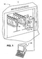
- a typical smart tag detection configuration is depicted generally in Figure 1 .
- Conductive or passive micro memory chips (“smart tags” 14 may consist of a microchip comprising silicon or other semiconductors, a coiled, etched, or stamped antennae, a capacitor, and a substrate on which the components are mounted or embedded. A protective covering is typically used to encapsulate and seal the substrate.
- inductive or passive smart tags have been introduced by Motorola under the name "BiStatix". A detailed description of the BiStatix device may be found in U.S. Patent No. 6,259,367 B1 .
- RFI D systems include those marketed by Microchip Technologies (Chandler, Arizona); the I*CODE chips and readers of Philips Semiconductor (Eindhoven, The Netherlands); the RFID products of Sokymat (Lausanne, Switzerland); the TI*RFID TM Systems and Tag It TM chips of Texas Instruments (Dallas, Texas); and the products of Gemplus (Gemenos, France), Nedap (Groenlo, The Netherlands), Checkpoint Systems Inc. (Miami, Florida), and Omron Company (Tokyo, Japan).
- High frequency bands can be used, exemplified by the 2.45 GHz products of SCS Corporation (Rancho Bernardo, California.
- a related technology within the scope of the present invention is Surface Acoustic Wave (SAW) technology.
- SAW Surface Acoustic Wave
- InfoRay Cambridge, Massachusetts markets a passive smart tag that is said to achieve long ranges (up to 30 meters) using a Surface Acoustic Wave (SAW) device.
- SAW Surface Acoustic Wave
- the SAW device converts a radio signal to an acoustic wave, modulates it with an ID code, then transforms it to another radio signal that is emitted by the smart tag and read by a scanner.
- the ID code of the smart tag is extracted from the radio signal.
- the scanner is said to compare the spectral content of the signal with a database of signatures and to derive the ID code. This method enables a read range of up to 30 m (typical 10-20 m).
- the system can operate In the 915MHz band and 2.45GHz band.
- RFSAW, Inc. (Dallas, Texas) also provides minute Surface Acoustic Wave (SAW) RFID devices that can be used within the scope of the present invention.
- Smart tags can include read-write systems or write-only systems.
- An embedded antennae within the smart tags 14 can be a useful component of the device, through it is recognized that alternatives to antennas may exist in some applications.
- the smart tag need not comprise an antenna but the metallic object itself can serve as the antenna.
- An excitation trigger signal 18 from a RFID scanner 16 must be received by the antennae to "activate" the smart tag 14.
- the received excitation signal 18 is the power source for the smart tag 14 and results in the generation of an electromagnetic pulse containing a coded product Information signal 20.
- a detailed description of RFID smart tag antennas and technology may also be found In U.S. Patent No. 6,320,556 B1 .
- an RFID scanner For commercial applications, an RFID scanner must be able to read multiple signals from a plurality of smart tags and to discriminate and focus only on the signals of interest.
- the problem of RFID scanners encountering multiple signals has been recognized in the art. Anti-collision algorithms may be used to sort through multiple signals, but such systems have limitations. It is unlikely that RFID scanners can be reasonably equipped to process large numbers of simultaneous RFID signals, such as 1,000 or more, or 10,000 or more simultaneous signals. It is also unlikely from a commercial feasibility standpoint to equip RFID scanners with processing circuitry necessary to effectively handle the complexities created by active signal jamming that confuses the scanner with transient random signals, spot frequency jamming, or broadband barrage jamming. These inherent drawbacks of smart tag scanners can be exploited for purposes of creating effective jamming techniques.
- Fig. graphically illustrates a typical smart tag detection system wherein smart tags 14. are attached or embedded in any manner of articles 12.
- a smart tag scanner 16 is disposed at a location to detect and interrogate products associated with smart tags 14 coming within range of the scanner 16.
- the scanner 16 may be disposed at the exit or entrance to a store, departments within the store, checkout counters, etc.
- the scanner 16 is disposed so as to detect the types of products or-articles a consumer has purchased in a particular department, or is actually wearing in the case of embedded smart tags 14 in the consumer's clothes, etc.
- the scanner 16 may be operationally configured with any manner of computer network (graphically illustrated as computer 20) wherein the received and decoded product information signals are processed and analyzed for any number of reasons. Still referring to Fig. 1 , the consumer may carry on their person a jamming device 30 in accordance with the present invention to inhibit the scanner 16 from effectively detecting smart tags 14 in any products purchased or otherwise associated with the consumer.
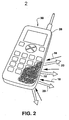
- Fig. 2 is a graphic representation of a passive RFID jamming device 30 in accordance with the teachings of the invention.
- the device 30 may be disguised as any conventional item or article that is typically and inconspicuously associated with consumers.
- the device 30 includes a structure 28 disguised as a conventional cellular telephone. This is for illustrative purposes only.
- the structure 28 may be disguised, for example, as any manner of consumer electronic item, such as a pager, camera, personal CD player, radio, etc. In an alternate embodiment, it is not necessary that the scanner 30 actually be visible.
- the jamming device 30 may be of a size and proportion so as to discretely fit within the individual's pocket, purse, briefcase, backpack, and the like.
- the structure 28 defines an interior volume in which a plurality of RFID chips 32 are stored.
- the number of chips may, vary, but should be great enough so as to generate a sufficient number of random RFID signals to overwhelm the RFID scanner 16.
- the number of chips and signals will obviously vary depending on the type of RFID system and such number may be empirically determined.
- the present inventors contemplate that 10,000 or more chips may be sufficient to render current RFID scanner technology ineffective. However, it should be recognized that this number may be greater or larger depending on the RFID system.
- the scanner's excitation trigger signals 18 "excite” or activate the plurality of jamming chips 32 causing each chip 32 to transmit an electromagnetic pulse signal 20.
- the plurality of pulse signals 20 are received by the scanner 16 and are of such a large number so as to prevent the scanner 16 from effectively detecting or recognizing legitimate product information signals 20 transmitted by any product associated smart tags 14.
- RFID jamming system and methodology according to the invention is not limited to any particular scenario.
- the jamming device may be used wherever an individual desires to inhibit smart tag technology from intruding into the individual's private life.
Abstract
Description
- The present invention relates generally to the field of RFID technology, and more particularly to a jamming device against RFID systems.
DE 297 14 999 U1 discloses a prior art device four the protection of a transponder against unauthorised readers.US 6,429,768 B1 discloses a prior art radio frequency jammer for preventing the transponder reader of a vehicle immobiliser from receiving signals from a transponder such as an ignition key. - Radio Frequency Identification Devices (RFIDs) are low-cost, passive "smart" chips or "tags" that can be embedded in or attached to articles, products, and the like to convey information about the product via a scanner. The smart tags are generally small label-like devices with a microchip and a miniature embedded antennae. The tags may be passive or active, the active tags requiring an internal power supply. A reader or scanner interrogates the smart tag with an electronic "trigger" signal. The tag in turn generates an electromagnetic pulse response that is readable by the scanner, the response containing the product information. RFID smart tags can be embedded in or attached to product packaging, or incorporated directly into the product, and may convey conventional "bar code" information, as well as other more detailed information.
- Various commercial applications have been suggested for smart tags, particularly in the area of retail marketing and sales. For example, RFID technology may be used to gather information related to consumer trends, purchasing habits, consumption rates, etc. It has also been suggested that RFID technology has promise in the areas of inventory control, manufacturing process and control, product accountability and tracking systems, etc. Manufacturers, shippers, and retailers may be able to follow a given product through their respective systems from initial production through to point of sale. It has been suggested that other applications may include shopping carts that automatically charge a bank account, refrigerators that tap into the Internet to automatically reorder items that are running low, and interactive televisions linked to such refrigerators that will feed targeted commercials and special offers to consumers. (See, "They Know What You Eat," by Kayte VanScoy, Smart Business, January 2001).
- Although RFID technology may provide benefits to the commercial sector, certain individuals may view particular uses of the technology as intrusive and an invasion of privacy. For example, some consumers refuse to use of "loyalty" cards at supermarkets even if a significant discount is offered because they object to the notion that their purchases are being tracked and analyzed. Such consumers may be less than enthused at the possibility that smart chips or tags embedded in their clothing, for example, may disclose their purchasing habits or likes and dislikes when they walk past a smart tag scanner at the entrance of a store. Consumers may object to being selectively targeted by telemarketers or mass mailings based on the smart tagged products they purchased at a store.
- The present invention relates to a novel implementation of jamming devices to inhibit unwanted intrusions of RFID technology.
- Objects and advantages of the invention will be set forth in the following description, or may be obvious from the description, or may be learned through practice of the invention.
- The present invention provides a RFID technology jamming system and method to inhibit unwanted intrusions of RFID technology into an individual's personal life. The device and method of the present invention is intended to prevent RFID smart tag systems from detecting and identifying products purchased or worn by an individual, or otherwise associated with or belonging to an individual. The present invention provides a jamming device as set forth in
claim 1 which is characterised over the disclosure ofDE 297 14 999 U1 . - A jamming device in accordance with an embodiment of the present invention comprises a passive device comprising a structure containing a large number of RFID chips. When the chips are "excited" by a trigger excitation signal from a nearby scanner, the chips simultaneously generate an electromagnetic response pulse. The number of chips is so great that the scanner is overwhelmed by the response pulses and cannot read the multiple responses rapidly enough and discriminate between these responses and any "legitimate" responses generated by any product smart tags.
- The structure containing the RFID jamming chips is not limited in any manner and, desirably, may be disguised as any type of item typically carried or worn by a consumer- For example, the structure may be configured to look like a cellular telephone, pager, camera, or the like. The passive jamming device may have a size so as to fit within a pocket, purse, briefcase, backpack, belt, pen, button on an item of clothing, a shirt label, a shoe, a dental filling, a wristwatch, and so forth. Ways in which to hide or disguise the passive jamming device will be readily apparent to those of skill in the art.
- In one embodiment, the jamming device can be activated or deactivated at the will of the user to prevent others from scanning smart tags except under certain circumstances. For example, some users of smart cards containing personal and financial information may fear that others may use scanners to obtain their personal information (e.g., account numbers and access codes), Such smart cards can be protected with a jamming device that is turned off when the smart card is to be used by a legitimate scanner. Passive jamming devices may employ antennas that can be disabled or disconnected by actions such as squeezing or bending a flexible card, pulling a tab, pressing a button, and the like, or the passive jamming device may be shielded by a Faraday cage, a metal cover, or a layer of dense material such as concrete, or may simply be removed from the presence of the smart card or other objects comprising smart tags when the user wishes to allow the smart tags to be scanned. For example, an automated teller at a bank adapted to read smart tags in a smart-card may be equipped with a shielding device into which a jamming device can be temporarily placed to prevent jamming, or there may be removal means such as a pneumatic tube or conveyor system to momentarily allow the jamming device to be carried a distance away from a smart tag reader to prevent jamming.
- Additional aspects of the present methodology and system will be described below with reference to the figures.
-
-
Figure 1 is a graphic illustration of concepts according to a method and system of the invention. -
Figure 2 is a graphic illustration of a passive RFID jamming device according to the intention. - Reference will now be made in detail to one or more embodiments of the invention, examples of which are graphically illustrated in the drawings. Each example and embodiment are provided by way of explanation of the Invention, and not meant as a limitation of the invention. For example, features illustrated or described as part of one embodiment may be utilized with another embodiment to yield still a further embodiment. It is intended that the present invention include these and other modifications and variations.
- RFID smart tag technology is known and understood by those skilled in the art, and a detailed explanation thereof is not necessary for purposes of describing the method and system according to the present invention. A typical smart tag detection configuration is depicted generally in
Figure 1 . Conductive or passive micro memory chips ("smart tags" 14 may consist of a microchip comprising silicon or other semiconductors, a coiled, etched, or stamped antennae, a capacitor, and a substrate on which the components are mounted or embedded. A protective covering is typically used to encapsulate and seal the substrate. inductive or passive smart tags have been introduced by Motorola under the name "BiStatix". A detailed description of the BiStatix device may be found inU.S. Patent No. 6,259,367 B1 . Another commercial source of suitable smart tags is Allen Technology Corporation of Morgan Hill, California, under the technology name FSA (Fluidic Self-Assembly). With the FSA process, tiny semi-conductor devices are assembled into rolls of flexible plastic. The resulting "smart" substrate can be attached to or embedded in any variety of products. The smart tag technology under development at the Auto-ID Center at Massachusetts Institute of Technology (Cambridge, Mass.) can also be used within the scope of the present invention. Further information on smart tags and related technology is disclosed inUS Patent No. 6,451,154 , "RFID Manufacturing Concepts," issued Sep. 17, 2002 to Grabau et al.;US Patent No. 6,354,493 , "System and Method for Finding a Specific RFID Tagged Article Located in a Plurality of RFID Tagged Articles," issued Mar. 12, 2002 to Mon;PCT publication WO 02/48955 US 2002/070862 ;US Patent No. 6,362,738 , "Reader for Use in a Radio Frequency Identification System and Method," issued Mar. 26, 2002 to Vega; D. McFarlane, "Auto-ID Based Control," White Paper for the Auto-ID Centre Institute for Manufacturing, University of Cambridge, Cambridge, United Kingdom, Feb. 1, 2002, available at hftp://www.autoidcenter.org/eesearch/CAM-AUTOID-WH-004.pdf; and Chien Yaw Wong, "Integration of Auto-ID Tagging System with Holonic Manufacturing Systems," White Paper for the Auto-ID Centre Institute for Manufacturing, University of Cambridge, Cambridge, United Kingdom, Sept. 2001, available at www.autoidcenter.org/research/CAM-WH-001.pdf . - Other examples of commercial RFI D systems include those marketed by Microchip Technologies (Chandler, Arizona); the I*CODE chips and readers of Philips Semiconductor (Eindhoven, The Netherlands); the RFID products of Sokymat (Lausanne, Switzerland); the TI*RFID™ Systems and Tag It™ chips of Texas Instruments (Dallas, Texas); and the products of Gemplus (Gemenos, France), Nedap (Groenlo, The Netherlands), Checkpoint Systems Inc. (Miami, Florida), and Omron Company (Tokyo, Japan). High frequency bands can be used, exemplified by the 2.45 GHz products of SCS Corporation (Rancho Bernardo, California.
- A related technology within the scope of the present invention is Surface Acoustic Wave (SAW) technology. For example, InfoRay (Cambridge, Massachusetts) markets a passive smart tag that is said to achieve long ranges (up to 30 meters) using a Surface Acoustic Wave (SAW) device. On a chip coupled with an antenna. The SAW device converts a radio signal to an acoustic wave, modulates it with an ID code, then transforms it to another radio signal that is emitted by the smart tag and read by a scanner. The ID code of the smart tag is extracted from the radio signal. The scanner is said to compare the spectral content of the signal with a database of signatures and to derive the ID code. This method enables a read range of up to 30 m (typical 10-20 m). The system can operate In the 915MHz band and 2.45GHz band. RFSAW, Inc. (Dallas, Texas) also provides minute Surface Acoustic Wave (SAW) RFID devices that can be used within the scope of the present invention. Smart tags can include read-write systems or write-only systems.
- An embedded antennae within the
smart tags 14 can be a useful component of the device, through it is recognized that alternatives to antennas may exist in some applications. For example, for some metallic objects, the smart tag need not comprise an antenna but the metallic object itself can serve as the antenna. Anexcitation trigger signal 18 from aRFID scanner 16 must be received by the antennae to "activate" thesmart tag 14. The receivedexcitation signal 18 is the power source for thesmart tag 14 and results in the generation of an electromagnetic pulse containing a codedproduct Information signal 20. A detailed description of RFID smart tag antennas and technology may also be found InU.S. Patent No. 6,320,556 B1 . - For commercial applications, an RFID scanner must be able to read multiple signals from a plurality of smart tags and to discriminate and focus only on the signals of interest. The problem of RFID scanners encountering multiple signals has been recognized in the art. Anti-collision algorithms may be used to sort through multiple signals, but such systems have limitations. It is unlikely that RFID scanners can be reasonably equipped to process large numbers of simultaneous RFID signals, such as 1,000 or more, or 10,000 or more simultaneous signals. It is also unlikely from a commercial feasibility standpoint to equip RFID scanners with processing circuitry necessary to effectively handle the complexities created by active signal jamming that confuses the scanner with transient random signals, spot frequency jamming, or broadband barrage jamming. These inherent drawbacks of smart tag scanners can be exploited for purposes of creating effective jamming techniques.
- As mentioned, Fig. graphically illustrates a typical smart tag detection system wherein
smart tags 14. are attached or embedded in any manner ofarticles 12. Asmart tag scanner 16 is disposed at a location to detect and interrogate products associated withsmart tags 14 coming within range of thescanner 16. For example, thescanner 16 may be disposed at the exit or entrance to a store, departments within the store, checkout counters, etc. In the illustrated scenario, thescanner 16 is disposed so as to detect the types of products or-articles a consumer has purchased in a particular department, or is actually wearing in the case of embeddedsmart tags 14 in the consumer's clothes, etc. Thescanner 16 may be operationally configured with any manner of computer network (graphically illustrated as computer 20) wherein the received and decoded product information signals are processed and analyzed for any number of reasons. Still referring toFig. 1 , the consumer may carry on their person a jammingdevice 30 in accordance with the present invention to inhibit thescanner 16 from effectively detectingsmart tags 14 in any products purchased or otherwise associated with the consumer. -
Fig. 2 is a graphic representation of a passiveRFID jamming device 30 in accordance with the teachings of the invention. Thedevice 30 may be disguised as any conventional item or article that is typically and inconspicuously associated with consumers. For example, in the illustrated embodiment, thedevice 30 includes astructure 28 disguised as a conventional cellular telephone. This is for illustrative purposes only. Thestructure 28 may be disguised, for example, as any manner of consumer electronic item, such as a pager, camera, personal CD player, radio, etc. In an alternate embodiment, it is not necessary that thescanner 30 actually be visible. The jammingdevice 30 may be of a size and proportion so as to discretely fit within the individual's pocket, purse, briefcase, backpack, and the like. - Still referring to
Fig. 2 , thestructure 28 defines an interior volume in which a plurality of RFID chips 32 are stored. The number of chips may, vary, but should be great enough so as to generate a sufficient number of random RFID signals to overwhelm theRFID scanner 16. The number of chips and signals will obviously vary depending on the type of RFID system and such number may be empirically determined. The present inventors contemplate that 10,000 or more chips may be sufficient to render current RFID scanner technology ineffective. However, it should be recognized that this number may be greater or larger depending on the RFID system. - Referring to
Fig. 1 , as theconsumer 30 approaches or comes within range of thescanner 16, the scanner's excitation trigger signals 18 "excite" or activate the plurality of jamming chips 32 causing each chip 32 to transmit anelectromagnetic pulse signal 20. The plurality of pulse signals 20 are received by thescanner 16 and are of such a large number so as to prevent thescanner 16 from effectively detecting or recognizing legitimate product information signals 20 transmitted by any product associatedsmart tags 14. - It should be appreciated that the RFID jamming system and methodology according to the invention is not limited to any particular scenario. The jamming device may be used wherever an individual desires to inhibit smart tag technology from intruding into the individual's private life.
- It should be appreciated by those skilled in the art that the system and method according to the invention have wide applications, and that the example and embodiments set forth herein are merely exemplary. It is intended that the present invention include such uses and embodiments as come within the scope of the appended claims.
Claims (5)
- A jamming device (30) for inhibiting unwanted intrusions from RFID smart tag technology, said device (30) comprising means for inhibiting smart chip RFID scanners (16) from accurately receiving information from smart tags (14) associated with products (12), wherein said inhibiting means comprises a passive device,
characterised in that said passive device comprises a structure (28) containing at least 1,000 RFID chips (32) so as to overwhelm a RFID scanner (16) with simultaneous RFID signals (20) to an extent that the scanner (16) cannot process such signals. - The device (30) as in claim 1, wherein said structure (28) comprises at least 10,000 RFID chips (32).
- The device (30) as in any preceding claim, wherein said device (30) is portable so as to be carried or worn by an individual.
- The device (30) as in any preceding claim, wherein said structure (28) is disguised as a consumer electronic device.
- The device (30) as in any preceding claim, wherein said structure (28) is of a size so as to fit within one of a pocket, purse, briefcase, or backpack.
Priority Applications (1)
| Application Number | Priority Date | Filing Date | Title |
|---|---|---|---|
| EP09000483A EP2065838A3 (en) | 2002-11-21 | 2003-07-10 | Jamming device against RFID smart tag systems |
Applications Claiming Priority (3)
| Application Number | Priority Date | Filing Date | Title |
|---|---|---|---|
| US301549 | 2002-11-21 | ||
| US10/301,549 US7221900B2 (en) | 2002-11-21 | 2002-11-21 | Jamming device against RFID smart tag systems |
| PCT/US2003/021827 WO2004049246A1 (en) | 2002-11-21 | 2003-07-10 | Jamming device against rfid smart tag systems |
Related Child Applications (1)
| Application Number | Title | Priority Date | Filing Date |
|---|---|---|---|
| EP09000483A Division EP2065838A3 (en) | 2002-11-21 | 2003-07-10 | Jamming device against RFID smart tag systems |
Publications (2)
| Publication Number | Publication Date |
|---|---|
| EP1579381A1 EP1579381A1 (en) | 2005-09-28 |
| EP1579381B1 true EP1579381B1 (en) | 2009-07-01 |
Family
ID=32324556
Family Applications (2)
| Application Number | Title | Priority Date | Filing Date |
|---|---|---|---|
| EP09000483A Withdrawn EP2065838A3 (en) | 2002-11-21 | 2003-07-10 | Jamming device against RFID smart tag systems |
| EP03811998A Expired - Fee Related EP1579381B1 (en) | 2002-11-21 | 2003-07-10 | Jamming device against rfid smart tag systems |
Family Applications Before (1)
| Application Number | Title | Priority Date | Filing Date |
|---|---|---|---|
| EP09000483A Withdrawn EP2065838A3 (en) | 2002-11-21 | 2003-07-10 | Jamming device against RFID smart tag systems |
Country Status (10)
| Country | Link |
|---|---|
| US (1) | US7221900B2 (en) |
| EP (2) | EP2065838A3 (en) |
| JP (1) | JP4339261B2 (en) |
| KR (1) | KR20050084664A (en) |
| AU (1) | AU2003249180A1 (en) |
| CA (1) | CA2505413A1 (en) |
| DE (1) | DE60328224D1 (en) |
| MX (1) | MXPA05004837A (en) |
| WO (1) | WO2004049246A1 (en) |
| ZA (1) | ZA200503648B (en) |
Families Citing this family (68)
| Publication number | Priority date | Publication date | Assignee | Title |
|---|---|---|---|---|
| US6970070B2 (en) * | 2003-05-08 | 2005-11-29 | Rsa Security Inc. | Method and apparatus for selective blocking of radio frequency identification devices |
| WO2005006488A1 (en) * | 2003-07-10 | 2005-01-20 | Upm-Kymmene Corporation | Planar antenna |
| JP4666451B2 (en) * | 2003-08-19 | 2011-04-06 | 三菱電機株式会社 | Identification tag system |
| US20050058292A1 (en) * | 2003-09-11 | 2005-03-17 | Impinj, Inc., A Delaware Corporation | Secure two-way RFID communications |
| CN1886750A (en) * | 2003-11-27 | 2006-12-27 | 皇家飞利浦电子股份有限公司 | Jammer for tags and smart cards |
| US7327802B2 (en) * | 2004-03-19 | 2008-02-05 | Sirit Technologies Inc. | Method and apparatus for canceling the transmitted signal in a homodyne duplex transceiver |
| US7088248B2 (en) * | 2004-03-24 | 2006-08-08 | Avery Dennison Corporation | System and method for selectively reading RFID devices |
| US7920050B2 (en) * | 2004-07-29 | 2011-04-05 | Emc Corporation | Proxy device for enhanced privacy in an RFID system |
| WO2006015145A2 (en) * | 2004-07-29 | 2006-02-09 | Rsa Security Inc. | Methods and apparatus for rfid device authentication |
| FR2875975B1 (en) * | 2004-09-27 | 2009-05-15 | Commissariat Energie Atomique | NON-CONTACT DEVICE FOR EXTENDING PRIVACY |
| JP4682582B2 (en) * | 2004-10-27 | 2011-05-11 | ヤマハ株式会社 | RFID tag reading / informing device, accommodating device, and RFID tag reading / informing sheet |
| GB2419781A (en) * | 2004-10-29 | 2006-05-03 | Hewlett Packard Development Co | Packaging of a transponder device |
| TWI260549B (en) * | 2004-12-14 | 2006-08-21 | Ind Tech Res Inst | Electronic tag reading design method concealing partial information |
| US7086587B2 (en) * | 2004-12-16 | 2006-08-08 | International Business Machines Corporation | Anti-tracking system to ensure consumer privacy |
| US7429984B2 (en) * | 2005-02-04 | 2008-09-30 | Philip Morris Usa Inc. | Display management system |
| US8624740B2 (en) * | 2005-02-04 | 2014-01-07 | Philip Morris Usa Inc. | Controllable RFID card |
| WO2006087503A1 (en) | 2005-02-15 | 2006-08-24 | Vodafone Group Plc | Improved security for wireless communication |
| KR100783084B1 (en) * | 2005-04-28 | 2007-12-11 | 이지현 | Rfid system having security apparatus and controlling method thereof |
| US20060273176A1 (en) * | 2005-06-03 | 2006-12-07 | Actividentity, Inc. | Blocking contactless personal security device |
| FR2888652B1 (en) * | 2005-07-18 | 2007-10-12 | Oberthur Card Syst Sa | ACTIVE SECURING METHOD AND DEVICE FOR NON-CONTACT ELECTRONIC DEVICE |
| US7889056B2 (en) * | 2005-10-31 | 2011-02-15 | Curio, Ltd. | RFID protection system, device, combination, and related methods |
| US8102243B2 (en) * | 2005-10-31 | 2012-01-24 | Curio Ltd. | RFID protection device, and related methods |
| CA2631152C (en) | 2005-12-07 | 2014-02-18 | Sca Hygiene Products Ab | Supply package for use in an apparatus for dispensing sheet material and an apparatus for dispensing sheet material |
| US8378786B2 (en) * | 2006-02-03 | 2013-02-19 | Emc Corporation | Security provision in standards-compliant RFID systems |
| CA2678423A1 (en) * | 2006-02-14 | 2007-08-23 | Ronald N. Miller | Rfid sensor system for lateral discrimination |
| US8226003B2 (en) | 2006-04-27 | 2012-07-24 | Sirit Inc. | Adjusting parameters associated with leakage signals |
| US7887755B2 (en) * | 2006-09-20 | 2011-02-15 | Binforma Group Limited Liability Company | Packaging closures integrated with disposable RFID devices |
| US7684751B2 (en) * | 2006-09-26 | 2010-03-23 | Intel Corporation | Radio frequency identification apparatus, system and method adapted for self-jammer cancellation |
| FR2908205B1 (en) * | 2006-11-03 | 2009-02-27 | Xiring Sa | DEVICE FOR PROTECTING FRAUD FROM CONTACTLESS COMMUNICATION OBJECTS |
| WO2008062331A2 (en) * | 2006-11-23 | 2008-05-29 | International Business Machines Corporation | Privacy method, device and computer program |
| US7612671B2 (en) * | 2006-11-29 | 2009-11-03 | Motorola, Inc. | Attachment device, attachment receiving device and system for identifying secured containers |
| FR2914518B1 (en) * | 2007-03-27 | 2009-05-01 | Commissariat Energie Atomique | SECURE COMMUNICATION SYSTEM BETWEEN A CONTACTLESS CARD READER AND A CARD. |
| US20080246611A1 (en) * | 2007-04-04 | 2008-10-09 | John King | Method and apparatus for detecting the presence of rfid devices and modifying the same |
| US8248212B2 (en) | 2007-05-24 | 2012-08-21 | Sirit Inc. | Pipelining processes in a RF reader |
| AU2008285349A1 (en) * | 2007-08-08 | 2009-02-12 | Radeum, Inc. | Near field communications system having enhanced security |
| EP2193652A4 (en) * | 2007-09-26 | 2014-03-05 | Radeum Inc Dba Freelinc | System and method for near field communications having local security |
| US8427316B2 (en) | 2008-03-20 | 2013-04-23 | 3M Innovative Properties Company | Detecting tampered with radio frequency identification tags |
| US8446256B2 (en) * | 2008-05-19 | 2013-05-21 | Sirit Technologies Inc. | Multiplexing radio frequency signals |
| US8169312B2 (en) * | 2009-01-09 | 2012-05-01 | Sirit Inc. | Determining speeds of radio frequency tags |
| US8113435B2 (en) * | 2009-01-28 | 2012-02-14 | Cubic Corporation | Card reader |
| US8350668B2 (en) * | 2009-01-29 | 2013-01-08 | Cubic Corporation | Smartcard protocol transmitter |
| US9509436B2 (en) | 2009-01-29 | 2016-11-29 | Cubic Corporation | Protection of near-field communication exchanges |
| US20100289623A1 (en) * | 2009-05-13 | 2010-11-18 | Roesner Bruce B | Interrogating radio frequency identification (rfid) tags |
| US8416079B2 (en) * | 2009-06-02 | 2013-04-09 | 3M Innovative Properties Company | Switching radio frequency identification (RFID) tags |
| US20110205025A1 (en) * | 2010-02-23 | 2011-08-25 | Sirit Technologies Inc. | Converting between different radio frequencies |
| EP2588589B2 (en) | 2010-07-02 | 2023-07-19 | The Procter & Gamble Company | Process for the production of a detergent product |
| EP2588655B1 (en) | 2010-07-02 | 2017-11-15 | The Procter and Gamble Company | Method for delivering an active agent |
| US9094057B2 (en) * | 2010-08-25 | 2015-07-28 | Qualcomm Incorporated | Parasitic circuit for device protection |
| US8723649B2 (en) * | 2011-02-15 | 2014-05-13 | Raytheon Company | Antenna for protecting radio frequency communications |
| US10062025B2 (en) | 2012-03-09 | 2018-08-28 | Neology, Inc. | Switchable RFID tag |
| US9129200B2 (en) * | 2012-10-30 | 2015-09-08 | Raytheon Corporation | Protection system for radio frequency communications |
| US9135548B2 (en) | 2012-11-29 | 2015-09-15 | Paypal, Inc. | Portable mechanical switch for selective deactivation of radio frequency identification circuits |
| CN104969594A (en) * | 2012-12-05 | 2015-10-07 | 哈利斯蒂斯有限公司 | Inhibiting unauthorised contactless reading of a contactless readable object |
| WO2014171955A1 (en) | 2013-04-19 | 2014-10-23 | Curio Ltd. | Rfid disruption device and related methods |
| US20150002273A1 (en) * | 2013-06-28 | 2015-01-01 | Hand Held Products, Inc. | Rfid tag blocking |
| US11308462B2 (en) | 2014-05-13 | 2022-04-19 | Clear Token Inc | Secure electronic payment |
| US9979427B2 (en) * | 2014-09-09 | 2018-05-22 | Ppip Llc | Privacy and security systems and methods of use |
| EP3381211B1 (en) * | 2016-02-26 | 2021-08-11 | Hewlett Packard Enterprise Development LP | Device privacy protection |
| US10423811B2 (en) | 2017-03-29 | 2019-09-24 | Walmart Apollo, Llc | Garment including RFID reader |
| GB2568915A (en) * | 2017-11-30 | 2019-06-05 | Moran Humberto | Reshaping interrogation range |
| CN108960359A (en) * | 2018-06-06 | 2018-12-07 | 北京银鞍技术有限公司 | Personal belongings management method and system |
| US11551537B2 (en) | 2019-04-11 | 2023-01-10 | Nexite Ltd. | Wireless dual-mode identification tag |
| EP3954053A1 (en) | 2019-04-11 | 2022-02-16 | Nexite Ltd. | Wireless dual-mode identification tag |
| MX2023001042A (en) | 2020-07-31 | 2023-02-16 | Procter & Gamble | Water-soluble fibrous pouch containing prills for hair care. |
| RU200438U1 (en) * | 2020-08-04 | 2020-10-23 | Общество с ограниченной ответственностью "Велтер" (ООО "Велтер") | Information exchange protection device when using a personal infocommunication device |
| EP4275160A1 (en) | 2021-01-11 | 2023-11-15 | Nexite Ltd. | Contactless and automatic operations of a retail store |
| US20230186234A1 (en) | 2021-12-13 | 2023-06-15 | Nexite Ltd. | Systems and methods for electronic determination of conversion rates |
| FR3136912A1 (en) * | 2022-06-16 | 2023-12-22 | Orange | Monitoring and management processes for communicating objects, trusted equipment, servers and communicating objects |
Family Cites Families (60)
| Publication number | Priority date | Publication date | Assignee | Title |
|---|---|---|---|---|
| US2885543A (en) * | 1945-01-27 | 1959-05-05 | Everard M Williams | Automatic sweeping and jamming radio equipment |
| US4217550A (en) * | 1962-09-28 | 1980-08-12 | Blassel Pierre P | Radio jamming device |
| US4656463A (en) | 1983-04-21 | 1987-04-07 | Intelli-Tech Corporation | LIMIS systems, devices and methods |
| US5047614A (en) | 1989-01-23 | 1991-09-10 | Bianco James S | Method and apparatus for computer-aided shopping |
| US5164707A (en) | 1990-02-28 | 1992-11-17 | Cabot Safety Corporation | Detection system for safety equipment |
| US5361070B1 (en) | 1993-04-12 | 2000-05-16 | Univ California | Ultra-wideband radar motion sensor |
| US5380991A (en) | 1993-11-16 | 1995-01-10 | Valencia; Luis | Paperless coupon redemption system and method thereof |
| US5677927A (en) | 1994-09-20 | 1997-10-14 | Pulson Communications Corporation | Ultrawide-band communication system and method |
| US5832035A (en) | 1994-09-20 | 1998-11-03 | Time Domain Corporation | Fast locking mechanism for channelized ultrawide-band communications |
| US5687169A (en) | 1995-04-27 | 1997-11-11 | Time Domain Systems, Inc. | Full duplex ultrawide-band communication system and method |
| US5606322A (en) * | 1994-10-24 | 1997-02-25 | Motorola, Inc. | Divergent code generator and method |
| US6690796B1 (en) * | 1995-05-17 | 2004-02-10 | The Chamberlain Group, Inc. | Rolling code security system |
| US5727153A (en) | 1995-06-06 | 1998-03-10 | Powell; Ken R. | Retail store having a system of receiving electronic coupon information from a portable card and sending the received coupon information to other portable cards |
| US6272341B1 (en) * | 1995-11-30 | 2001-08-07 | Motient Services Inc. | Network engineering/systems engineering system for mobile satellite communication system |
| US5918211A (en) | 1996-05-30 | 1999-06-29 | Retail Multimedia Corporation | Method and apparatus for promoting products and influencing consumer purchasing decisions at the point-of-purchase |
| US6446049B1 (en) | 1996-10-25 | 2002-09-03 | Pole/Zero Corporation | Method and apparatus for transmitting a digital information signal and vending system incorporating same |
| KR100199015B1 (en) * | 1996-11-25 | 1999-06-15 | 정선종 | Fm demodulator |
| DE19653291C1 (en) * | 1996-12-20 | 1998-04-02 | Pepperl & Fuchs | Sensor and evaluation system for end position and threshold value detection |
| US6112052A (en) * | 1997-01-29 | 2000-08-29 | Northrop Grumman Corporation | Remote controlled noise jamming device |
| US6435407B1 (en) | 1997-03-25 | 2002-08-20 | Luigi Fiordelisi | Computerized shopping cart with storage and distribution system, for supermarket use |
| US5955969A (en) | 1997-04-09 | 1999-09-21 | Texas Instruments Incorporated | Method to prevent rouge transponder responses in automatic vehicle identification systems |
| US5963134A (en) | 1997-07-24 | 1999-10-05 | Checkpoint Systems, Inc. | Inventory system using articles with RFID tags |
| US6409086B1 (en) | 1997-08-08 | 2002-06-25 | Symbol Technolgies, Inc. | Terminal locking system |
| DE29714999U1 (en) | 1997-08-21 | 1997-10-09 | Trebe Elektronik Gmbh & Co Kg | Device for protecting a transponder against unauthorized reading and / or deleting and / or overwriting the data of the transponder |
| DE19742126A1 (en) | 1997-09-24 | 1999-03-25 | Siemens Ag | Portable data medium with activation switch |
| US6037879A (en) | 1997-10-02 | 2000-03-14 | Micron Technology, Inc. | Wireless identification device, RFID device, and method of manufacturing wireless identification device |
| US6249227B1 (en) | 1998-01-05 | 2001-06-19 | Intermec Ip Corp. | RFID integrated in electronic assets |
| US6362738B1 (en) | 1998-04-16 | 2002-03-26 | Motorola, Inc. | Reader for use in a radio frequency identification system and method thereof |
| US5942978A (en) * | 1998-04-24 | 1999-08-24 | Sensormatic Electronics Corporation | Wireless transmitter key for EAS tag detacher unit |
| US6123259A (en) | 1998-04-30 | 2000-09-26 | Fujitsu Limited | Electronic shopping system including customer relocation recognition |
| US6640214B1 (en) | 1999-01-16 | 2003-10-28 | Symbol Technologies, Inc. | Portable electronic terminal and data processing system |
| US6332128B1 (en) | 1998-07-23 | 2001-12-18 | Autogas Systems, Inc. | System and method of providing multiple level discounts on cross-marketed products and discounting a price-per-unit-volume of gasoline |
| AU762475B2 (en) * | 1998-08-14 | 2003-06-26 | 3M Innovative Properties Company | Applications for radio frequency identification systems |
| CA2343404C (en) | 1998-09-11 | 2002-11-12 | Key-Trak, Inc. | Object tracking system with non-contact object detection and identification |
| US6226619B1 (en) | 1998-10-29 | 2001-05-01 | International Business Machines Corporation | Method and system for preventing counterfeiting of high price wholesale and retail items |
| EP1049042A1 (en) | 1999-04-28 | 2000-11-02 | The Procter & Gamble Company | Storage system |
| AU5732600A (en) * | 1999-06-11 | 2001-01-02 | Creative Golf Designs, Inc. | Inventory control system |
| US6218979B1 (en) | 1999-06-14 | 2001-04-17 | Time Domain Corporation | Wide area time domain radar array |
| US6177903B1 (en) | 1999-06-14 | 2001-01-23 | Time Domain Corporation | System and method for intrusion detection using a time domain radar array |
| US6429768B1 (en) * | 1999-09-09 | 2002-08-06 | Kenneth E. Flick | Vehicle control system including transponder jammer and related methods |
| US6693511B1 (en) | 1999-09-24 | 2004-02-17 | Ge Interlogix, Inc. | System and method for communicating with dormant radio frequency identification tags |
| US6259367B1 (en) | 1999-09-28 | 2001-07-10 | Elliot S. Klein | Lost and found system and method |
| US7933780B2 (en) * | 1999-10-22 | 2011-04-26 | Telaric, Llc | Method and apparatus for controlling an infusion pump or the like |
| US6354493B1 (en) | 1999-12-23 | 2002-03-12 | Sensormatic Electronics Corporation | System and method for finding a specific RFID tagged article located in a plurality of RFID tagged articles |
| US6320556B1 (en) | 2000-01-19 | 2001-11-20 | Moore North America, Inc. | RFID foil or film antennas |
| US6497656B1 (en) | 2000-02-08 | 2002-12-24 | General Electric Company | Integrated wireless broadband communications network |
| US6587835B1 (en) | 2000-02-09 | 2003-07-01 | G. Victor Treyz | Shopping assistance with handheld computing device |
| US6451154B1 (en) | 2000-02-18 | 2002-09-17 | Moore North America, Inc. | RFID manufacturing concepts |
| WO2001069429A2 (en) | 2000-03-15 | 2001-09-20 | International Paper | Controlled remote product internet access and distribution |
| SE522000C2 (en) | 2000-08-18 | 2004-01-07 | Rutger Roseen | Method and apparatus for keeping track of the shelf life of goods stored in a room |
| JP2002163722A (en) | 2000-11-29 | 2002-06-07 | Kojima Co Ltd | Method, device, and portable terminal for merchandise sales management |
| US6600418B2 (en) | 2000-12-12 | 2003-07-29 | 3M Innovative Properties Company | Object tracking and management system and method using radio-frequency identification tags |
| US6951596B2 (en) * | 2002-01-18 | 2005-10-04 | Avery Dennison Corporation | RFID label technique |
| US6491217B2 (en) | 2001-03-31 | 2002-12-10 | Koninklijke Philips Electronics N.V. | Machine readable label reader system with versatile response selection |
| US6758397B2 (en) | 2001-03-31 | 2004-07-06 | Koninklijke Philips Electronics N.V. | Machine readable label reader system for articles with changeable status |
| US6694177B2 (en) | 2001-04-23 | 2004-02-17 | Cardionet, Inc. | Control of data transmission between a remote monitoring unit and a central unit |
| US6942155B1 (en) * | 2001-05-31 | 2005-09-13 | Alien Technology Corporation | Integrated circuits with persistent data storage |
| US6707381B1 (en) | 2001-06-26 | 2004-03-16 | Key-Trak, Inc. | Object tracking method and system with object identification and verification |
| US7809087B2 (en) * | 2002-04-26 | 2010-10-05 | Qualcomm, Incorporated | Power detection techniques and discrete gain state selection for wireless networking |
| US6707376B1 (en) | 2002-08-09 | 2004-03-16 | Sensormatic Electronics Corporation | Pulsed power method for increased read range for a radio frequency identification reader |
-
2002
- 2002-11-21 US US10/301,549 patent/US7221900B2/en active Active
-
2003
- 2003-07-10 KR KR1020057007919A patent/KR20050084664A/en not_active Application Discontinuation
- 2003-07-10 DE DE60328224T patent/DE60328224D1/en not_active Expired - Fee Related
- 2003-07-10 JP JP2004555275A patent/JP4339261B2/en not_active Expired - Fee Related
- 2003-07-10 AU AU2003249180A patent/AU2003249180A1/en not_active Abandoned
- 2003-07-10 WO PCT/US2003/021827 patent/WO2004049246A1/en active Application Filing
- 2003-07-10 MX MXPA05004837A patent/MXPA05004837A/en active IP Right Grant
- 2003-07-10 EP EP09000483A patent/EP2065838A3/en not_active Withdrawn
- 2003-07-10 ZA ZA200503648A patent/ZA200503648B/en unknown
- 2003-07-10 CA CA002505413A patent/CA2505413A1/en not_active Abandoned
- 2003-07-10 EP EP03811998A patent/EP1579381B1/en not_active Expired - Fee Related
Also Published As
| Publication number | Publication date |
|---|---|
| CA2505413A1 (en) | 2004-06-10 |
| EP2065838A3 (en) | 2009-08-19 |
| US20040100359A1 (en) | 2004-05-27 |
| EP2065838A2 (en) | 2009-06-03 |
| ZA200503648B (en) | 2008-03-26 |
| EP1579381A1 (en) | 2005-09-28 |
| MXPA05004837A (en) | 2005-07-22 |
| AU2003249180A1 (en) | 2004-06-18 |
| JP2006507599A (en) | 2006-03-02 |
| KR20050084664A (en) | 2005-08-26 |
| JP4339261B2 (en) | 2009-10-07 |
| US7221900B2 (en) | 2007-05-22 |
| WO2004049246A1 (en) | 2004-06-10 |
| DE60328224D1 (en) | 2009-08-13 |
Similar Documents
| Publication | Publication Date | Title |
|---|---|---|
| EP1579381B1 (en) | Jamming device against rfid smart tag systems | |
| Chawla et al. | An overview of passive RFID | |
| US20070075145A1 (en) | Jammer for tags and smart cards | |
| KR100660447B1 (en) | Applications for radio frequency identification systems | |
| Karjoth et al. | Disabling RFID tags with visible confirmation: clipped tags are silenced | |
| EP1625557B1 (en) | Article identification and tracking using electronic shadows created by rfid tags | |
| CA2610432C (en) | Techniques for detecting rfid tags in electronic article surveillance systems using frequency mixing | |
| US7839276B2 (en) | Secure self scan | |
| US7086587B2 (en) | Anti-tracking system to ensure consumer privacy | |
| US9514342B1 (en) | Wearable radio frequency identification enabled devices | |
| US20130015243A1 (en) | Applications for radio frequency identification systems | |
| EP3909031B1 (en) | Systems and methods for using radio frequency identification as an adaptive alarm threshold | |
| Khattab et al. | Introduction to RFID | |
| US20050289247A1 (en) | Interactive system using electronic tags | |
| US20150027831A1 (en) | Security lining | |
| Srinivasan et al. | RFID security and privacy concerns. | |
| Rao et al. | RFID security threats to consumers: Hype vs. reality | |
| Singh et al. | Radio frequency identification: applications and security issues | |
| Biswas | Applicability and usability of RFID technology in library | |
| Kamran | RFID and Information Security | |
| AU2003204067B2 (en) | Applications for radio frequency identification systems | |
| Lewan | Microchips everywhere: A future vision | |
| Macaulay et al. | RADIO FREQUENCY IDENTIFICATION (RFID) | |
| TEDJINI et al. | A TECHNOLOGY FOR THE FUTURE? |
Legal Events
| Date | Code | Title | Description |
|---|---|---|---|
| PUAI | Public reference made under article 153(3) epc to a published international application that has entered the european phase |
Free format text: ORIGINAL CODE: 0009012 |
|
| 17P | Request for examination filed |
Effective date: 20050527 |
|
| AK | Designated contracting states |
Kind code of ref document: A1 Designated state(s): AT BE BG CH CY CZ DE DK EE ES FI FR GB GR HU IE IT LI LU MC NL PT RO SE SI SK TR |
|
| AX | Request for extension of the european patent |
Extension state: AL LT LV MK |
|
| DAX | Request for extension of the european patent (deleted) | ||
| RBV | Designated contracting states (corrected) |
Designated state(s): DE FR GB IT SE |
|
| GRAP | Despatch of communication of intention to grant a patent |
Free format text: ORIGINAL CODE: EPIDOSNIGR1 |
|
| GRAS | Grant fee paid |
Free format text: ORIGINAL CODE: EPIDOSNIGR3 |
|
| GRAA | (expected) grant |
Free format text: ORIGINAL CODE: 0009210 |
|
| AK | Designated contracting states |
Kind code of ref document: B1 Designated state(s): DE FR GB IT SE |
|
| REG | Reference to a national code |
Ref country code: GB Ref legal event code: FG4D |
|
| REF | Corresponds to: |
Ref document number: 60328224 Country of ref document: DE Date of ref document: 20090813 Kind code of ref document: P |
|
| PGFP | Annual fee paid to national office [announced via postgrant information from national office to epo] |
Ref country code: FR Payment date: 20090717 Year of fee payment: 7 |
|
| PGFP | Annual fee paid to national office [announced via postgrant information from national office to epo] |
Ref country code: GB Payment date: 20090727 Year of fee payment: 7 Ref country code: DE Payment date: 20090729 Year of fee payment: 7 |
|
| PG25 | Lapsed in a contracting state [announced via postgrant information from national office to epo] |
Ref country code: SE Free format text: LAPSE BECAUSE OF FAILURE TO SUBMIT A TRANSLATION OF THE DESCRIPTION OR TO PAY THE FEE WITHIN THE PRESCRIBED TIME-LIMIT Effective date: 20090701 |
|
| REG | Reference to a national code |
Ref country code: GB Ref legal event code: 732E Free format text: REGISTERED BETWEEN 20100114 AND 20100120 |
|
| PLBE | No opposition filed within time limit |
Free format text: ORIGINAL CODE: 0009261 |
|
| STAA | Information on the status of an ep patent application or granted ep patent |
Free format text: STATUS: NO OPPOSITION FILED WITHIN TIME LIMIT |
|
| REG | Reference to a national code |
Ref country code: FR Ref legal event code: TP |
|
| 26N | No opposition filed |
Effective date: 20100406 |
|
| GBPC | Gb: european patent ceased through non-payment of renewal fee |
Effective date: 20100710 |
|
| PG25 | Lapsed in a contracting state [announced via postgrant information from national office to epo] |
Ref country code: IT Free format text: LAPSE BECAUSE OF FAILURE TO SUBMIT A TRANSLATION OF THE DESCRIPTION OR TO PAY THE FEE WITHIN THE PRESCRIBED TIME-LIMIT Effective date: 20090701 |
|
| REG | Reference to a national code |
Ref country code: FR Ref legal event code: ST Effective date: 20110331 |
|
| PG25 | Lapsed in a contracting state [announced via postgrant information from national office to epo] |
Ref country code: DE Free format text: LAPSE BECAUSE OF NON-PAYMENT OF DUE FEES Effective date: 20110201 |
|
| REG | Reference to a national code |
Ref country code: DE Ref legal event code: R119 Ref document number: 60328224 Country of ref document: DE Effective date: 20110201 |
|
| PG25 | Lapsed in a contracting state [announced via postgrant information from national office to epo] |
Ref country code: FR Free format text: LAPSE BECAUSE OF NON-PAYMENT OF DUE FEES Effective date: 20100802 |
|
| PG25 | Lapsed in a contracting state [announced via postgrant information from national office to epo] |
Ref country code: GB Free format text: LAPSE BECAUSE OF NON-PAYMENT OF DUE FEES Effective date: 20100710 |