EP1579536B1 - Cable connector and method of assembling a cable to such a cable connector - Google Patents
Cable connector and method of assembling a cable to such a cable connector Download PDFInfo
- Publication number
- EP1579536B1 EP1579536B1 EP03796097A EP03796097A EP1579536B1 EP 1579536 B1 EP1579536 B1 EP 1579536B1 EP 03796097 A EP03796097 A EP 03796097A EP 03796097 A EP03796097 A EP 03796097A EP 1579536 B1 EP1579536 B1 EP 1579536B1
- Authority
- EP
- European Patent Office
- Prior art keywords
- cable connector
- die
- housing part
- cast
- cable
- Prior art date
- Legal status (The legal status is an assumption and is not a legal conclusion. Google has not performed a legal analysis and makes no representation as to the accuracy of the status listed.)
- Expired - Lifetime
Links
- 238000000034 method Methods 0.000 title description 5
- 239000002184 metal Substances 0.000 claims description 27
- 229910052751 metal Inorganic materials 0.000 claims description 27
- 235000012431 wafers Nutrition 0.000 claims description 20
- 230000000712 assembly Effects 0.000 description 4
- 238000000429 assembly Methods 0.000 description 4
- 238000003780 insertion Methods 0.000 description 4
- 230000037431 insertion Effects 0.000 description 4
- 230000004308 accommodation Effects 0.000 description 2
- 238000005452 bending Methods 0.000 description 2
- 238000004519 manufacturing process Methods 0.000 description 2
- 239000011159 matrix material Substances 0.000 description 2
- 239000007769 metal material Substances 0.000 description 2
- 230000010287 polarization Effects 0.000 description 2
- RYGMFSIKBFXOCR-UHFFFAOYSA-N Copper Chemical compound [Cu] RYGMFSIKBFXOCR-UHFFFAOYSA-N 0.000 description 1
- 229910001229 Pot metal Inorganic materials 0.000 description 1
- 238000010521 absorption reaction Methods 0.000 description 1
- 229910052802 copper Inorganic materials 0.000 description 1
- 239000010949 copper Substances 0.000 description 1
- 230000003247 decreasing effect Effects 0.000 description 1
- 238000004512 die casting Methods 0.000 description 1
- 230000009977 dual effect Effects 0.000 description 1
- 238000002347 injection Methods 0.000 description 1
- 239000007924 injection Substances 0.000 description 1
Images


Classifications
-
- H—ELECTRICITY
- H01—ELECTRIC ELEMENTS
- H01R—ELECTRICALLY-CONDUCTIVE CONNECTIONS; STRUCTURAL ASSOCIATIONS OF A PLURALITY OF MUTUALLY-INSULATED ELECTRICAL CONNECTING ELEMENTS; COUPLING DEVICES; CURRENT COLLECTORS
- H01R13/00—Details of coupling devices of the kinds covered by groups H01R12/70 or H01R24/00 - H01R33/00
- H01R13/46—Bases; Cases
- H01R13/502—Bases; Cases composed of different pieces
- H01R13/5025—Bases; Cases composed of different pieces one or more pieces being of resilient material
-
- H—ELECTRICITY
- H01—ELECTRIC ELEMENTS
- H01R—ELECTRICALLY-CONDUCTIVE CONNECTIONS; STRUCTURAL ASSOCIATIONS OF A PLURALITY OF MUTUALLY-INSULATED ELECTRICAL CONNECTING ELEMENTS; COUPLING DEVICES; CURRENT COLLECTORS
- H01R43/00—Apparatus or processes specially adapted for manufacturing, assembling, maintaining, or repairing of line connectors or current collectors or for joining electric conductors
- H01R43/18—Apparatus or processes specially adapted for manufacturing, assembling, maintaining, or repairing of line connectors or current collectors or for joining electric conductors for manufacturing bases or cases for contact members
Definitions
- the invention relates to a cable connector comprising a housing having a die-cast base substantially extending between a front side and a rear side of said connector.
- cable connectors in e.g. telecom applications have to meet a package of ever increasing requirements relating to e.g. robustness, quality of assembly, aesthetical considerations, density, shielding etc.
- US 6,217,364 discloses an electrical connector assembly, wherein the housing of the electrical connector comprises two halves of die-cast metal material extending between a front opening and a rear opening, An electrical cable includes a plurality of electrical wires that are terminated to a plurality of wafers juxtaposed in a parallel array that is positioned in one of the housing halves.
- US 6 019 627 discloses a cable connector having two part plastic injection moulded housing formed of a lower part and a cover. The lower part and the cover accomodate a plug body having a metallic shield.
- US 2002/0146926 A1 discloses a plug connector and a receptable connector assembly for high-density interconnection of data cables. The cable connection portions are die-cast and have a reduced profile.
- US 5244415 discloses a computer cable connector having a base and a cover from die-cast zinc which form a chamber to receive the shielded cable.
- connection panels comprising header assemblies for a cable connector have openings for insertion of cable connectors. The dimensions of these openings are decreasing to obtain a high density, such that limitation of the minimum wall thickness of a housing of a cable connector constitutes a constraint with respect to the density of cable connectors on such a connection panel.
- Such a cable connector combines a die-cast base with a metal sheet formed housing part at the front side.
- the metal sheet formed housing part provides the possibility to limit the front side wall thickness of the cable connector housing, such that the front side of this cable connector can be inserted in a connecting panel with openings of smaller dimensions, while still using die-cast parts.
- Die-cast parts generally allow a large freedom with respect to shapability of such a part.
- the die-case base which extends between the front side and the back side of the entire housing provides rigidity to this cable connector.
- such a cable connector can be easily provided with polarization features for insertion in a header, since the die-cast edge at the front side can be manufactured with sharp contours, while the metal sheet formed housing part edge at the front side will have more smooth contours.
- the die-cast first housing part is a modular first housing part and the first portion is a ferrule holder portion. Since the first portion may be constituted solely of die-cast metal parts, this portion may have a complex shape with several protrusions, slots, recesses etc. As a result a robust first connector portion is obtained, which may meet aesthetical requirements. Requirements relating to robustness and aesthetics are particularly relevant for I/O cable connectors. Moreover, by having a modular first housing part, i.e.
- the first housing part is a separate component
- a cable can be positioned in the complex formed die-cast base, such that a ferrule associated with this cable can be fixed in the ferrule holder by subsequently mounting the separate die-cast first housing part to the die-cast base.
- the first cable connector portion further may have a shaft protruding outwardly from the first connector portion to protect the cable from getting punctured by sharp edges of the housing.
- the metal sheet formed second housing part is a modular second housing part and said second portion of the die-cast base comprises a receiving structure for the second housing part.
- the receiving structure is arranged such that the dimensions of the cable connector at the front side can be kept to a minimum to enable high density.
- the wall thickness of at least the part of the second portion to be inserted in the opening in the connecting of said die-cast base is approximately 0,4 - 0,6 mm. This is about the minimum limit for reliable die-casting structures.
- the second cable connector portion comprises an opening at the front side and the connecting means are substantially located within the second cable connector portion.
- the withdrawn location of the connecting means from the front side provides the advantage of robustness, since the connecting means are well protected and hold tightly within the housing. Furthermore the connecting means are prevented from twisting or rotating with respect to the cable connector.
- the die-cast base may comprise a wire management portion and/or a connecting means portion with reception means adapted for receiving the connecting means.
- reception means can be easily obtained in the die-cast process of manufacturing the die-cast base.
- the reception means preferably are adapted to cooperate with protrusion or holes in the connecting means.
- the connecting means may comprise one or more individual or stacked wafers for termination of the cable wires comprising holes to cooperate with the protrusions and/or reception means.
- Such an arrangement of connecting means facilitates assembly of the cable connector as individual as well as stacked wafers and connecting blocks can be applied in the connecting means portions employing, mounting or fitting the corresponding reception means, protrusions, holes on the various connector parts and connecting means.
- the reception means may e.g. be a pillar running through the connecting means and fixed at both ends in the die-cast base and the metal sheet formed second housing part.
- the die-cast base comprises one or more ridges. Since the die-cast base preferably has a wall thickness close to the minimum wall thickness that can be obtained in the die-cast process, the ridges provide mechanical strength or robustness to at least the thin die-cast base portion. Preferably the ridges are located in at least a part of the second portion of said die-cast base and extend in an axial direction of the cable connector. More preferably the ridges are located in the wire management portion. The ridges can be easily obtained in the die-cast process of manufacturing the die-cast base. By providing these ridges at least in the wire management section, the ridges moreover may assist in management of the cable wires terminating at the first wafer of the stack in the connecting means portion.
- the ridges may have one or more protrusions extending from the ridge in a direction substantially perpendicular to the axial direction as to assist in cable wire management for wires terminating at subsequent wafers of the stack in the connecting means portion.
- Wire management of the cable wires is e.g. needed to guide the cable wires from the e.g. spherical arrangement in the cable to the matrix arrangement of the connecting block of the connecting means.
- the metal sheet formed housing part comprises spring contacts adapted to be received in the first portion of the die-cast base.
- the die-cast base, the die-cast first housing part and the metal sheet formed second housing part may all be finished products satisfying particular tolerance requirements. These spring contacts allow absorption of mutual tolerances and provide adequate electrical connection between the die-cast base and the metal sheet formed housing part for shielding, since the die-cast base, the die-cast first housing part and the metal sheet formed second housing part are squeezed together and with the ferrule of the cable.
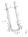
- FIG. 1 an I/O 8-pair twinax cable connector 1 is shown, comprising a die-cast base 2, hereinafter also referred to as base 2, extending between a front side 3 and a rear side 4.
- a cable 5 provided with a ferrule arrangement 6 is assembled to the connector 1 at the rear side 4.
- the connector 1 further comprises a die-cast first housing part 7 and a metal sheet formed second housing part 8, which housing parts 7, 8 are not mounted to the base 2 for clarity purposes in Fig. 1 .
- Housing parts 7 and 8 are modular parts, i.e. they are separate components adapted to engage with the base 2.
- Base 2 comprises a first portion 9 and a second portion 10 determining a first cable connector portion or ferrule portion with the first housing part 7 and a second connector portion with the second housing part 8 respectively.
- the second portion 10 comprises a wire management portion and a connecting means portion (indicated in Fig. 3 ) comprising cable wires 11 and connecting means 12, the latter exposed at the front side 3 of the cable connector 1 where an opening 13 is determined by an edge 14 of the second base portion 10 and the edges 15, 16, 17 of the second housing part 8.
- Edge 14 may be given a sharp contour, while edges 15, 16 and 17 of the second housing part 8 will have more smooth contours, providing polarization for insertion in a panel as e.g. shown in Fig. 2 .
- the connecting means 12 are substantially located within the second cable connector portion.
- the connecting means 12 are located within the second cable connector portion with respect to the edge 14 of the die-cast base 2 and the edge 16 of the second housing part 8, while the connecting means 12 do slightly protrude from the second cable connector portion with respect to the edges 15 and 17.
- the cable connector 1 comprises a screw 18 for mounting the cable connector to a panel or element thereof such as a header assembly. Detailed parts of the cable connector 1 will be discussed in relation to the Figs. 3-8 showing detailed views of the cable connector.
- Fig. 2 shows a front connecting panel 20 having cutout openings 21 for insertion of the second cable connector portions of the cable connector 1 as shown in Fig. 1 in header assemblies 22 connected to a board 23.
- Header assemblies 22 are subject of a co-pending application ("Shielding cage") of the applicant of the same date. Openings 21 of the high density front panel 20 e.g. have a height of 7,4mm and a width of 8,3mm. Since the connecting means 12 requires a given amount of space, only base 2 of cable connector 1 may be of die-cast metal with a wall thickness of e.g. 0,6mm.
- the second housing part 8 is a metal sheet formed housing part allowing a thinner wall, such as e.g. 0,3mm.
- the first cable connector portion or ferrule portion is not to be inserted in the opening 21 as a consequence of which this connector portion may be entirely of die-cast metal. Therefore this connector portion is robust and can be nicely shaped, making cable connector 1 appropriate to function as an I/O connector.
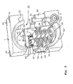
- Fig. 3 shows a detailed view of the die-cast base 2 of the cable connector 1 as shown in Fig. 1 .
- Base 2 comprises a first portion 9 and a second portion 10, the latter being divided in a wire management portion 31 and a connecting means portion 32.
- the first portion 9 comprises a cable entrance opening 33 and a internal structure. This structure e.g. comprises a structure to hold the ferrule arrangement 6 of the cable 5.
- the first portion 9 further comprises upstanding pillars 34 and a bubble 35 to receive the die-cast first housing part 7, as a consequence of which rigidity of the cable connector 1 is achieved or enhanced.
- first portion 9 comprises an integral structure 36 adapted for accommodation of screw 18. The required high density performance of the cable connector 1 may allow for accommodation of only one screw 18.
- the second portion 10 of base 2 comprises a receiving structure 37 to accommodate edges 41 and 42 (shown in Fig. 4 ) of the metal sheet formed second housing part 8 such that the outer dimensions of the front side 3 of the cable connector 1 can be kept to a minimum such that the second cable connector portion can be inserted in the openings 21 of a high density panel 20, shown in Fig. 2 .
- Receiving structure 37 may be a step-like structure.
- the second portion 10 comprises mounting structures 38 to cooperate with mounting structures 43 (shown in Fig. 4 ) of the second housing part 8 for fixating the second housing part 8 with the base 2, e.g. by snap-fitting.
- Wire management portion 31 of second portion 10 comprises ridges 39 along an axial direction of the base 2. Ridges 39 provide mechanical strength to the slender die-cast base portion 10, which has a minimum thickness of e.g. 0,6mm. It should be appreciated that ridges 39 may also extend to e.g. the end of base portion 10, i.e. up to edge 14, as to support the connecting means 12, or an alternative length. Moreover, ridges 39 may facilitate management of the cable wires 11 of the cable 5 by substantially matching the outer profiles of the cable wires 11 thereby orienting properly the wire pairs from the first connector portion to the connecting means 12. In the embodiment shown in Fig.
- ridges 39 may only manage the cable wires 11 for a first wafer of the stack of connecting means 11 in connecting means portion 32. However, since ridges 39 are manufactured in a die-cast process, these ridges may be formed with protrusions (not shown) extending in a direction substantially perpendicular to the axial direction, such that cable wires 11 of subsequent wafers in the stack in the connecting means portion 32 can be influenced as well.
- the length of the wire management portion 31 may depend on the diameter of the cable 5, such as e.g. 15 mm for an AWG26 cable.
- the wires 11 of the cable 5 are partially stripped and terminated on appropriate parts of the connecting means 12. The lengths of the wires 11 may be cut slightly larger than the distance between the end of the ferrule arrangement 6 and the wire termination part of the connecting means 12, to avoid transfer of mechanical forces to these termination parts if forces are applied to the cable 5.
- Connecting means portion 32 of base 2 may comprise reception means 40 for receiving elements of the connecting means 12, which will be described in Figs. 6-8 in more detail.
- Reception means 40 may comprise one or more pillars and/or holes adapted to receive separate pillars or protrusions (shown in Figs. 6-8 ) of the connecting means 12.
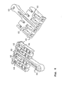
- Fig. 4 displays a metal sheet formed second housing part 8 as a U-shaped housing part determined by edges 15, 16 and 17 and elongated in an axial direction of the cable connector 1 by edges 41 and 42.
- Housing part 8 comprises mounting structures 43 that are adapted to cooperate with mounting structures 38 of the second potion 10 of base 2.
- Housing part 8 further comprises spring contacts 44 that cooperate with the internal structure of the first portion 9 of base 2 if the cable connector 1 is assembled. This part of the internal structure of first portion 9 is e.g. a curvilinear surface against which the spring contacts 44 are pressed.
- Spring contacts 44 are preferably be formed integral to the housing part 8 and absorb tolerances and provide reliable electrical contact between the die-cast base 2 and the housing part 8.
- housing part 8 comprises protrusions 45 that are sandwiched between the ferrule arrangement 6 and the die-cast first housing part 7 while assembling the cable connector 1. Moreover housing part 8 comprises dimples 46 for forcing the housing part 8 towards the base 2 when mounting the first housing part 7.
- Fig. 5 shows a rear view of the cable connector 1 as shown in Fig. 1 , without cable 5, but with cable wires 11.
- Fig. 5 shows the connecting means 12 in a twinax matrix configuration. Elements already discussed previously have been assigned identical reference numbers.
- the first connector portion or ferrule portion constituted by the die-cast first housing part 7 and the first portion 9 of the die-cast base 2 dimensions of e.g. 12mm in width and 14mm in height, i.e. significantly larger than the dimension of the second cable connector portion that is to be inserted in the small opening 21 of the panel 20.
- the die-cast first housing part 7 receives the protrusions 45 at the side of the metal sheet formed second housing part 8.
- the protrusions 45 are flexible to built up contact pressure and reliable electrical contact with the ferrule arrangement 6.
- the die-cast first housing part 7 comprises holes 50 for reception of the pillars 34 of the die-cast base 2 to achieve or enhance rigidity to the cable connector 1. Moreover, a shaft 51, 51' protrudes from the opening 52 of the first cable connector portion to support the mantle of the cable 5 over length of the shaft such that severe bending of the cable 5 does not result in puncture of the sharp edges of the housing in the mantle. Such severe bending is e.g. imposed to the cable 5 if such a cable 5 is routed in a standardized cabinet space of 38mm.
- the cable connector 1 may be suited for cable diameters with a maximum of e.g. 9,3mm.
- Figs. 6-8 show various embodiments of connecting means 12.
- Fig. 6 displays two views of a plastic connecting block 60 of connecting means 12, comprising signal contacts 62 and a ground contact 63 constituted as dual beam terminals and a fork contact respectively.
- Connecting block 60 comprises protrusions 64 and holes 65 that are adapted to cooperate with protrusions 64 of a subsequent connecting block 60.
- the connecting means 12 may be adapted to include a wafer providing signal and ground tracks as will be shown next for alternative connecting blocks.
- Protrusions 64 of the connecting block 60 that is positioned first in the connecting portion 32 may cooperate with a hole 40 of the die-cast base 2.
- Fig. 7 shows connecting means 12 with an alternative connecting block 70 and a wafer 71 for termination of the cable wires 11 of the cable 5.
- Wafer 71 is provided with a groove 72 for receiving the ground fork contact 63 and various holes 73 that are adapted to cooperate with the protrusions 74 of the connecting block 70.
- Protrusions 74 of the first positioned connecting block 70 may cooperate with the receiving means 40.
- wafer 71 is provided with a copper plate 75 for shielding purposes that is contacted via the holes 73 with the ground contact 63.
- Fig. 8 shows alternative connecting means 12 comprising connecting block 80 and a wafer 81, having signal tracks 82 and a ground track 83.
- the signal tracks 82 of the wafer 81 may be connected to electrical means 84, such as equalization or passive filters.
- the hole 85 of the connecting block 80 may receive one of the protrusions 74 of a below connecting block 70 via the suitable hole 73 in the wafer 71 and/or of the receiving means 40, such as a pillar, in the connecting portion 32 of the die-cast base 2 of the cable connector 1.
- the second portion 10 of the die-cast base 2, e.g. in the connecting means portion 32 comprises one or integral pillars as reception means 40 adapted to extend through corresponding holes of the connecting blocks 60, 70, 80 and wafers 71, 81.
- Metal sheet formed housing 8 may comprise recesses or holes to receive these integral pillars 40.
- cable connector 1 is shown connected to a header assembly 22 on a board 23 behind the front panel 20.
Abstract
Description
- The invention relates to a cable connector comprising a housing having a die-cast base substantially extending between a front side and a rear side of said connector.
- Nowadays, cable connectors in e.g. telecom applications have to meet a package of ever increasing requirements relating to e.g. robustness, quality of assembly, aesthetical considerations, density, shielding etc.
-
US 6,217,364 discloses an electrical connector assembly, wherein the housing of the electrical connector comprises two halves of die-cast metal material extending between a front opening and a rear opening, An electrical cable includes a plurality of electrical wires that are terminated to a plurality of wafers juxtaposed in a parallel array that is positioned in one of the housing halves.US 6 019 627 discloses a cable connector having two part plastic injection moulded housing formed of a lower part and a cover. The lower part and the cover accomodate a plug body having a metallic shield.US 2002/0146926 A1 discloses a plug connector and a receptable connector assembly for high-density interconnection of data cables. The cable connection portions are die-cast and have a reduced profile.US 5244415 discloses a computer cable connector having a base and a cover from die-cast zinc which form a chamber to receive the shielded cable. - A problem associated with the prior art cable connector is that the housing is manufactured from die-cast metal material which results in a minimum thickness for the walls of the connector housing. Connection panels comprising header assemblies for a cable connector have openings for insertion of cable connectors. The dimensions of these openings are decreasing to obtain a high density, such that limitation of the minimum wall thickness of a housing of a cable connector constitutes a constraint with respect to the density of cable connectors on such a connection panel.
- It is an object of the invention to provide a cable connector with an improved density performance.
- This object is achieved by providing a cable connector comprising
- a die-cast first housing part mounted to said die-cast base such that said die-cast first housing part and a first portion of said die-cast base determine a first cable connector portion at said rear side;
- a metal sheet formed second housing part mounted to said die-cast base such that said metal sheet formed second housing part
- Such a cable connector combines a die-cast base with a metal sheet formed housing part at the front side. The metal sheet formed housing part provides the possibility to limit the front side wall thickness of the cable connector housing, such that the front side of this cable connector can be inserted in a connecting panel with openings of smaller dimensions, while still using die-cast parts. Die-cast parts generally allow a large freedom with respect to shapability of such a part. The die-case base which extends between the front side and the back side of the entire housing provides rigidity to this cable connector. As an additional advantage, such a cable connector can be easily provided with polarization features for insertion in a header, since the die-cast edge at the front side can be manufactured with sharp contours, while the metal sheet formed housing part edge at the front side will have more smooth contours.
- In a preferred embodiment of the invention, the die-cast first housing part is a modular first housing part and the first portion is a ferrule holder portion. Since the first portion may be constituted solely of die-cast metal parts, this portion may have a complex shape with several protrusions, slots, recesses etc. As a result a robust first connector portion is obtained, which may meet aesthetical requirements. Requirements relating to robustness and aesthetics are particularly relevant for I/O cable connectors. Moreover, by having a modular first housing part, i.e. the first housing part is a separate component, a cable can be positioned in the complex formed die-cast base, such that a ferrule associated with this cable can be fixed in the ferrule holder by subsequently mounting the separate die-cast first housing part to the die-cast base. The first cable connector portion further may have a shaft protruding outwardly from the first connector portion to protect the cable from getting punctured by sharp edges of the housing.
- In a preferred embodiment of the invention the metal sheet formed second housing part is a modular second housing part and said second portion of the die-cast base comprises a receiving structure for the second housing part. The receiving structure is arranged such that the dimensions of the cable connector at the front side can be kept to a minimum to enable high density. Preferably the wall thickness of at least the part of the second portion to be inserted in the opening in the connecting of said die-cast base is approximately 0,4 - 0,6 mm. This is about the minimum limit for reliable die-casting structures.
- In a preferred embodiment of the invention the second cable connector portion comprises an opening at the front side and the connecting means are substantially located within the second cable connector portion. The withdrawn location of the connecting means from the front side provides the advantage of robustness, since the connecting means are well protected and hold tightly within the housing. Furthermore the connecting means are prevented from twisting or rotating with respect to the cable connector.
- In a preferred embodiment the die-cast base may comprise a wire management portion and/or a connecting means portion with reception means adapted for receiving the connecting means. These reception means can be easily obtained in the die-cast process of manufacturing the die-cast base. The reception means preferably are adapted to cooperate with protrusion or holes in the connecting means. Further the connecting means may comprise one or more individual or stacked wafers for termination of the cable wires comprising holes to cooperate with the protrusions and/or reception means. Such an arrangement of connecting means facilitates assembly of the cable connector as individual as well as stacked wafers and connecting blocks can be applied in the connecting means portions employing, mounting or fitting the corresponding reception means, protrusions, holes on the various connector parts and connecting means. The reception means may e.g. be a pillar running through the connecting means and fixed at both ends in the die-cast base and the metal sheet formed second housing part.
- In a preferred embodiment of the invention, the die-cast base comprises one or more ridges. Since the die-cast base preferably has a wall thickness close to the minimum wall thickness that can be obtained in the die-cast process, the ridges provide mechanical strength or robustness to at least the thin die-cast base portion. Preferably the ridges are located in at least a part of the second portion of said die-cast base and extend in an axial direction of the cable connector. More preferably the ridges are located in the wire management portion. The ridges can be easily obtained in the die-cast process of manufacturing the die-cast base. By providing these ridges at least in the wire management section, the ridges moreover may assist in management of the cable wires terminating at the first wafer of the stack in the connecting means portion. The ridges may have one or more protrusions extending from the ridge in a direction substantially perpendicular to the axial direction as to assist in cable wire management for wires terminating at subsequent wafers of the stack in the connecting means portion. Wire management of the cable wires is e.g. needed to guide the cable wires from the e.g. spherical arrangement in the cable to the matrix arrangement of the connecting block of the connecting means.
- In a preferred embodiment the metal sheet formed housing part comprises spring contacts adapted to be received in the first portion of the die-cast base. The die-cast base, the die-cast first housing part and the metal sheet formed second housing part may all be finished products satisfying particular tolerance requirements. These spring contacts allow absorption of mutual tolerances and provide adequate electrical connection between the die-cast base and the metal sheet formed housing part for shielding, since the die-cast base, the die-cast first housing part and the metal sheet formed second housing part are squeezed together and with the ferrule of the cable.
- It should be appreciated that the embodiments discussed above, or aspects thereof, can be combined.
- The invention will be further illustrated with reference to the attached drawing, which shows a preferred embodiment according to the invention. It will be understood that the cable connector according to the invention is not in any way restricted to this specific and preferred embodiment.
-
Fig. 1 shows a cable connector according to an embodiment of the invention; -
Fig. 2 shows a part of a connecting panel comprising header assemblies for connecting a cable connector according to an embodiment of the invention; -
Fig. 3 shows a die-cast base of a cable connector according to an embodiment of the invention; -
Fig. 4 shows a metal sheet formed second housing part for a cable connector according to an embodiment of the invention; -
Fig. 5 shows a rear view section of a cable connector as shown inFig. 1 ; -
Figs. 6-8 show embodiments of connecting means that may be applied in a cable connector as shown inFig. 1 . -
Fig. 9 shows a cable connector according to an embodiment of the invention connected to a front panel. - In
Fig. 1 an I/O 8-pairtwinax cable connector 1 is shown, comprising a die-cast base 2, hereinafter also referred to asbase 2, extending between afront side 3 and arear side 4. A cable 5 provided with aferrule arrangement 6 is assembled to theconnector 1 at therear side 4. Theconnector 1 further comprises a die-castfirst housing part 7 and a metal sheet formedsecond housing part 8, whichhousing parts base 2 for clarity purposes inFig. 1 .Housing parts base 2.Base 2 comprises afirst portion 9 and asecond portion 10 determining a first cable connector portion or ferrule portion with thefirst housing part 7 and a second connector portion with thesecond housing part 8 respectively. Thesecond portion 10 comprises a wire management portion and a connecting means portion (indicated inFig. 3 ) comprisingcable wires 11 and connectingmeans 12, the latter exposed at thefront side 3 of thecable connector 1 where anopening 13 is determined by anedge 14 of thesecond base portion 10 and theedges second housing part 8.Edge 14 may be given a sharp contour, whileedges second housing part 8 will have more smooth contours, providing polarization for insertion in a panel as e.g. shown inFig. 2 . The connecting means 12 are substantially located within the second cable connector portion. InFig. 1 the connectingmeans 12 are located within the second cable connector portion with respect to theedge 14 of the die-cast base 2 and theedge 16 of thesecond housing part 8, while the connecting means 12 do slightly protrude from the second cable connector portion with respect to theedges cable connector 1 comprises ascrew 18 for mounting the cable connector to a panel or element thereof such as a header assembly. Detailed parts of thecable connector 1 will be discussed in relation to theFigs. 3-8 showing detailed views of the cable connector. -
Fig. 2 shows a front connectingpanel 20 havingcutout openings 21 for insertion of the second cable connector portions of thecable connector 1 as shown inFig. 1 inheader assemblies 22 connected to aboard 23.Header assemblies 22 are subject of a co-pending application ("Shielding cage") of the applicant of the same date.Openings 21 of the highdensity front panel 20 e.g. have a height of 7,4mm and a width of 8,3mm. Since the connectingmeans 12 requires a given amount of space, only base 2 ofcable connector 1 may be of die-cast metal with a wall thickness of e.g. 0,6mm. According to the invention thesecond housing part 8 is a metal sheet formed housing part allowing a thinner wall, such as e.g. 0,3mm. - The first cable connector portion or ferrule portion is not to be inserted in the
opening 21 as a consequence of which this connector portion may be entirely of die-cast metal. Therefore this connector portion is robust and can be nicely shaped, makingcable connector 1 appropriate to function as an I/O connector. -
Fig. 3 shows a detailed view of the die-cast base 2 of thecable connector 1 as shown inFig. 1 .Base 2 comprises afirst portion 9 and asecond portion 10, the latter being divided in awire management portion 31 and a connectingmeans portion 32. Thefirst portion 9 comprises acable entrance opening 33 and a internal structure. This structure e.g. comprises a structure to hold theferrule arrangement 6 of the cable 5. Thefirst portion 9 further comprisesupstanding pillars 34 and abubble 35 to receive the die-castfirst housing part 7, as a consequence of which rigidity of thecable connector 1 is achieved or enhanced. Furthermorefirst portion 9 comprises anintegral structure 36 adapted for accommodation ofscrew 18. The required high density performance of thecable connector 1 may allow for accommodation of only onescrew 18. - The
second portion 10 ofbase 2 comprises a receivingstructure 37 to accommodateedges 41 and 42 (shown inFig. 4 ) of the metal sheet formedsecond housing part 8 such that the outer dimensions of thefront side 3 of thecable connector 1 can be kept to a minimum such that the second cable connector portion can be inserted in theopenings 21 of ahigh density panel 20, shown inFig. 2 . Receivingstructure 37 may be a step-like structure. Moreover thesecond portion 10 comprises mountingstructures 38 to cooperate with mounting structures 43 (shown inFig. 4 ) of thesecond housing part 8 for fixating thesecond housing part 8 with thebase 2, e.g. by snap-fitting. -
Wire management portion 31 ofsecond portion 10 comprisesridges 39 along an axial direction of thebase 2.Ridges 39 provide mechanical strength to the slender die-cast base portion 10, which has a minimum thickness of e.g. 0,6mm. It should be appreciated thatridges 39 may also extend to e.g. the end ofbase portion 10, i.e. up to edge 14, as to support the connectingmeans 12, or an alternative length. Moreover,ridges 39 may facilitate management of thecable wires 11 of the cable 5 by substantially matching the outer profiles of thecable wires 11 thereby orienting properly the wire pairs from the first connector portion to the connectingmeans 12. In the embodiment shown inFig. 3 ,ridges 39 may only manage thecable wires 11 for a first wafer of the stack of connectingmeans 11 in connectingmeans portion 32. However, sinceridges 39 are manufactured in a die-cast process, these ridges may be formed with protrusions (not shown) extending in a direction substantially perpendicular to the axial direction, such thatcable wires 11 of subsequent wafers in the stack in the connecting meansportion 32 can be influenced as well. The length of thewire management portion 31 may depend on the diameter of the cable 5, such as e.g. 15 mm for an AWG26 cable. Thewires 11 of the cable 5 are partially stripped and terminated on appropriate parts of the connectingmeans 12. The lengths of thewires 11 may be cut slightly larger than the distance between the end of theferrule arrangement 6 and the wire termination part of the connectingmeans 12, to avoid transfer of mechanical forces to these termination parts if forces are applied to the cable 5. - Connecting means
portion 32 ofbase 2 may comprise reception means 40 for receiving elements of the connectingmeans 12, which will be described inFigs. 6-8 in more detail. Reception means 40 may comprise one or more pillars and/or holes adapted to receive separate pillars or protrusions (shown inFigs. 6-8 ) of the connectingmeans 12. -
Fig. 4 displays a metal sheet formedsecond housing part 8 as a U-shaped housing part determined byedges cable connector 1 byedges Housing part 8 comprises mountingstructures 43 that are adapted to cooperate with mountingstructures 38 of thesecond potion 10 ofbase 2.Housing part 8 further comprisesspring contacts 44 that cooperate with the internal structure of thefirst portion 9 ofbase 2 if thecable connector 1 is assembled. This part of the internal structure offirst portion 9 is e.g. a curvilinear surface against which thespring contacts 44 are pressed.Spring contacts 44 are preferably be formed integral to thehousing part 8 and absorb tolerances and provide reliable electrical contact between the die-cast base 2 and thehousing part 8.Further housing part 8 comprisesprotrusions 45 that are sandwiched between theferrule arrangement 6 and the die-castfirst housing part 7 while assembling thecable connector 1. Moreoverhousing part 8 comprisesdimples 46 for forcing thehousing part 8 towards thebase 2 when mounting thefirst housing part 7. -
Fig. 5 shows a rear view of thecable connector 1 as shown inFig. 1 , without cable 5, but withcable wires 11.Fig. 5 shows the connecting means 12 in a twinax matrix configuration. Elements already discussed previously have been assigned identical reference numbers. The first connector portion or ferrule portion constituted by the die-castfirst housing part 7 and thefirst portion 9 of the die-cast base 2 dimensions of e.g. 12mm in width and 14mm in height, i.e. significantly larger than the dimension of the second cable connector portion that is to be inserted in thesmall opening 21 of thepanel 20. The die-castfirst housing part 7 receives theprotrusions 45 at the side of the metal sheet formedsecond housing part 8. Theprotrusions 45 are flexible to built up contact pressure and reliable electrical contact with theferrule arrangement 6. - The die-cast
first housing part 7 comprisesholes 50 for reception of thepillars 34 of the die-cast base 2 to achieve or enhance rigidity to thecable connector 1. Moreover, ashaft 51, 51' protrudes from theopening 52 of the first cable connector portion to support the mantle of the cable 5 over length of the shaft such that severe bending of the cable 5 does not result in puncture of the sharp edges of the housing in the mantle. Such severe bending is e.g. imposed to the cable 5 if such a cable 5 is routed in a standardized cabinet space of 38mm. Thecable connector 1 may be suited for cable diameters with a maximum of e.g. 9,3mm. -
Figs. 6-8 show various embodiments of connectingmeans 12.Fig. 6 displays two views of aplastic connecting block 60 of connectingmeans 12, comprisingsignal contacts 62 and aground contact 63 constituted as dual beam terminals and a fork contact respectively. Connectingblock 60 comprisesprotrusions 64 and holes 65 that are adapted to cooperate withprotrusions 64 of a subsequent connectingblock 60. The connecting means 12 may be adapted to include a wafer providing signal and ground tracks as will be shown next for alternative connecting blocks.Protrusions 64 of the connectingblock 60 that is positioned first in the connectingportion 32 may cooperate with ahole 40 of the die-cast base 2. -
Fig. 7 shows connecting means 12 with analternative connecting block 70 and awafer 71 for termination of thecable wires 11 of the cable 5.Wafer 71 is provided with agroove 72 for receiving theground fork contact 63 andvarious holes 73 that are adapted to cooperate with theprotrusions 74 of the connectingblock 70.Protrusions 74 of the first positioned connectingblock 70 may cooperate with the receiving means 40. Moreoverwafer 71 is provided with acopper plate 75 for shielding purposes that is contacted via theholes 73 with theground contact 63. -
Fig. 8 showsalternative connecting means 12 comprising connectingblock 80 and awafer 81, having signal tracks 82 and aground track 83. The signal tracks 82 of thewafer 81 may be connected toelectrical means 84, such as equalization or passive filters. Thehole 85 of the connectingblock 80 may receive one of theprotrusions 74 of a below connectingblock 70 via thesuitable hole 73 in thewafer 71 and/or of the receiving means 40, such as a pillar, in the connectingportion 32 of the die-cast base 2 of thecable connector 1. - It should be appreciated that other alternatives for positioning and mounting of the connecting means 12 in the cable connector are possible without departing from this element of the scope of the invention. It can e.g. be envisaged that the
second portion 10 of the die-cast base 2, e.g. in the connecting meansportion 32, comprises one or integral pillars as reception means 40 adapted to extend through corresponding holes of the connectingblocks wafers housing 8 may comprise recesses or holes to receive theseintegral pillars 40. - In
Fig. 9 cable connector 1 is shown connected to aheader assembly 22 on aboard 23 behind thefront panel 20.
Claims (16)
- Cable connector (1) comprising a housing having:- a die-cast base (2) substantially extending between a front side (3) and a rear side (4) of said connector (1);- a die-cast first housing part (7) mounted to said die-cast base (2) such that said die-cast first housing part (7) and a first portion (9) of said die-cast base (2) determine a first cable connector portion at said rear side (4);characterized in that the cable connector further comprises a metal sheet formed second housing part (8) mounted to said die-cast base (2) such that said metal sheet formed second housing part (8) and a second portion (10) of said die-cast base (2) determine a second cable connector portion at said front side (3) and in that said second cable connector portion comprises an opening (13) at said front side (3) and connecting means (12) located within said second cable connector portion with respect to at least one edge (14,15, 16, 17) determining said opening (13).
- Cable connector (1) according to claim 1, wherein said die-cast first housing part (7) is a modular first housing part and said first portion (9) of said die-cast base comprises a ferrule holder portion.
- Cable connector (1) according to claim 1 or 2, wherein said first cable connector portion comprises a cable entrance opening (52) at said rear side (4) and a shaft (51, 51'), outwardly protruding from said first cable connector portion.
- Cable connector (1) according to any one of the preceding claims, wherein said metal sheet formed second housing part (8) is a modular second housing part and said second portion (10) of said die-cast base (2) comprises a receiving structure (37) for said second housing part (8).
- Cable connector, (1) according to claim 4, wherein the wall thickness of said second portion (10) of said die-cast base (2) is approximately 0,4-0,6 mm.
- Cable connector (1) according to any of the preceding claims, wherein said second portion (10) of said die- cast base (2) comprises a wire management portion (31) and a connecting means portion (32) with reception means (40) adapted for receiving said connecting means (12).
- Cable connector (1) according to claims 6, wherein said connecting means (12) comprises one or more connecting blocks (60,70, 80), said connecting blocks (60,70, 80) comprising protrusions (64,74) and/or holes (65,85) adapted to cooperate with said reception means (40).
- Cable connector according to claim 7, wherein said connecting means (12) further comprises one or more wafers (71) associated with said connecting blocks (60,70, 80), said wafers (71) comprising holes (73) to cooperate with said protrusions (64,74) and/or said reception means (40).
- Cable connector (1) according to any of the preceding claims, wherein said cable connector (1) comprises connecting means (12) at said front side (3) with one or more wafers (71), said wafers (71) comprising a plurality of signal tracks (82) and/or ground tracks (83) for termination of cable wires (6).
- Cable connector (1) according to claims 9, wherein said wafers (71) comprise a shielding plane (75) on a side opposite to the side of said signal and/or ground tracks (82, 83).
- Cable connector (1) according to any one of the preceding claims, wherein said die-cast base (2) comprises one or more ridges (39).
- Cable connector (1) according to claim 11, wherein said ridges (39) are located in at least a part of said second portion (10) of said die-cast base (2) extending in an axial direction of said cable connector (1).
- Cable connector (1) according to claim 12, wherein said part of said second portion (10) of said die-cast base (2) is a wire management portion (31).
- Cable connector (1) according to claim 12 or 13, wherein at least one of said ridges in the connecting portion (32) of the die-cast base (2) of the cable connector (1) comprises one or more protrusions extending from said ridge (39) in a direction substantially perpendicular to said axial direction.
- Cable connector (1) according to any one of the preceding claims, wherein said metal sheet formed second housing part (8) comprises one or more protrusions (45) for mounting said metal sheet formed second housing part (8) to said die-cast first housing part (7).
- Cable connector (1) according to any one of the preceding claims, wherein said metal sheet formed second housing part (8) comprises spring contacts (44) adapted to be received by said first portion (9) of said die-cast base (2).
Priority Applications (1)
| Application Number | Priority Date | Filing Date | Title |
|---|---|---|---|
| EP10166848A EP2234214B1 (en) | 2002-12-20 | 2003-12-12 | Electrical cable connector. |
Applications Claiming Priority (3)
| Application Number | Priority Date | Filing Date | Title |
|---|---|---|---|
| NL1022225 | 2002-12-20 | ||
| NL1022225A NL1022225C2 (en) | 2002-12-20 | 2002-12-20 | Cable connector and method for joining a cable and such a cable connector. |
| PCT/EP2003/050993 WO2004057707A1 (en) | 2002-12-20 | 2003-12-12 | Cable connector and method of assembling a cable to such a cable connector |
Related Child Applications (1)
| Application Number | Title | Priority Date | Filing Date |
|---|---|---|---|
| EP10166848A Division-Into EP2234214B1 (en) | 2002-12-20 | 2003-12-12 | Electrical cable connector. |
Publications (2)
| Publication Number | Publication Date |
|---|---|
| EP1579536A1 EP1579536A1 (en) | 2005-09-28 |
| EP1579536B1 true EP1579536B1 (en) | 2012-08-22 |
Family
ID=32678025
Family Applications (2)
| Application Number | Title | Priority Date | Filing Date |
|---|---|---|---|
| EP10166848A Expired - Lifetime EP2234214B1 (en) | 2002-12-20 | 2003-12-12 | Electrical cable connector. |
| EP03796097A Expired - Lifetime EP1579536B1 (en) | 2002-12-20 | 2003-12-12 | Cable connector and method of assembling a cable to such a cable connector |
Family Applications Before (1)
| Application Number | Title | Priority Date | Filing Date |
|---|---|---|---|
| EP10166848A Expired - Lifetime EP2234214B1 (en) | 2002-12-20 | 2003-12-12 | Electrical cable connector. |
Country Status (8)
| Country | Link |
|---|---|
| US (1) | US7285017B2 (en) |
| EP (2) | EP2234214B1 (en) |
| KR (1) | KR20050084374A (en) |
| CN (1) | CN100477404C (en) |
| AT (1) | ATE527726T1 (en) |
| AU (1) | AU2003298356A1 (en) |
| NL (1) | NL1022225C2 (en) |
| WO (1) | WO2004057707A1 (en) |
Families Citing this family (3)
| Publication number | Priority date | Publication date | Assignee | Title |
|---|---|---|---|---|
| NL1026451C2 (en) * | 2004-06-18 | 2005-12-20 | Framatome Connectors Int | Cable connector and method for assembling a cable and such a cable connector. |
| NL1026863C2 (en) * | 2004-08-18 | 2006-02-21 | Framatome Connectors Int | Cable connector. |
| US9124008B2 (en) * | 2013-08-29 | 2015-09-01 | Tyco Electronics Corporation | Electrical connector |
Family Cites Families (39)
| Publication number | Priority date | Publication date | Assignee | Title |
|---|---|---|---|---|
| US4653836A (en) * | 1983-07-06 | 1987-03-31 | Amp Incorporated | Shielded electrical connector |
| US4902242A (en) * | 1989-05-31 | 1990-02-20 | Amp Incorporated | Panel mount, cable terminable connector with die cast housing and drawn shell |
| US4960392A (en) * | 1990-01-16 | 1990-10-02 | Dickie Robert G | Shielded connector assembly with noise suppressor |
| US5167523A (en) * | 1991-11-01 | 1992-12-01 | Harbor Electronics, Inc. | Electrical connector |
| US5244415A (en) * | 1992-02-07 | 1993-09-14 | Harbor Electronics, Inc. | Shielded electrical connector and cable |
| US5195909A (en) * | 1992-03-05 | 1993-03-23 | Amp Incorporated | Insulative backshell system providing strain relief and shield continuity |
| US5409400A (en) * | 1993-01-15 | 1995-04-25 | The Whitaker Corporation | Shielding for an electrical connector |
| GB9321180D0 (en) * | 1993-10-14 | 1993-12-01 | Amp Gmbh | Shielded connector with hermaphroditic shell |
| US5538440A (en) * | 1993-11-17 | 1996-07-23 | Thomas & Betts Corporation | Electrical connector having a conductor holding block |
| US5372513A (en) * | 1993-11-17 | 1994-12-13 | Thomas & Betts Corporation | Electrical connector with cable shield ground clip |
| US5387130A (en) * | 1994-03-29 | 1995-02-07 | The Whitaker Corporation | Shielded electrical cable assembly with shielding back shell |
| NL1000050C2 (en) * | 1995-04-05 | 1996-10-08 | Framatome Connectors Belgium | Connector. |
| US6036543A (en) * | 1996-04-04 | 2000-03-14 | Framatome Connectors International | Connector assembly |
| WO1997047058A1 (en) * | 1996-06-05 | 1997-12-11 | Berg Technology, Inc. | Shielded cable connector |
| US6019627A (en) * | 1996-06-25 | 2000-02-01 | Siemens Aktiengesellschaft | Plug connector having a connecting cable |
| DE19712810A1 (en) * | 1997-03-26 | 1998-10-01 | Whitaker Corp | Cable plug arrangement |
| US5831815A (en) * | 1997-03-31 | 1998-11-03 | The Whitaker Corporation | Programmable backshell for an electrical connector |
| US6231392B1 (en) * | 1997-10-01 | 2001-05-15 | Berg Technology, Inc. | Cable interconnection |
| US6328601B1 (en) * | 1998-01-15 | 2001-12-11 | The Siemon Company | Enhanced performance telecommunications connector |
| US6358091B1 (en) * | 1998-01-15 | 2002-03-19 | The Siemon Company | Telecommunications connector having multi-pair modularity |
| US6203333B1 (en) * | 1998-04-22 | 2001-03-20 | Stratos Lightwave, Inc. | High speed interface converter module |
| NL1009373C2 (en) * | 1998-06-11 | 1999-12-15 | Framatome Connectors Belgium | Connector for a shielded cable. |
| US6109976A (en) * | 1998-07-10 | 2000-08-29 | Berg Technology, Inc. | Modular high speed connector |
| US6017245A (en) * | 1998-08-19 | 2000-01-25 | Amphenol Corporation | Stamped backshell assembly with integral front shield and rear cable clamp |
| WO2000033430A1 (en) * | 1998-11-30 | 2000-06-08 | The Siemon Company | Preparation tool for shielded cables |
| SE520444C2 (en) * | 1999-01-29 | 2003-07-08 | Berg Connectors Sweden Ab | Connectors and method for assembling the connector |
| TW420418U (en) * | 1999-05-15 | 2001-01-21 | Hon Hai Prec Ind Co Ltd | Electrical cable connector |
| US6217364B1 (en) * | 1999-07-09 | 2001-04-17 | Molex Incorporated | Electrical connector assembly with guide pin latching system |
| NL1014035C2 (en) * | 2000-01-07 | 2001-07-10 | Fci S Hertogenbosch B V | Cable connector for a shielded cable. |
| NL1015059C2 (en) * | 2000-04-28 | 2001-10-30 | Fci S Hertogenbosch B V | Cable connector and kit for assembling it. |
| JP3405961B2 (en) * | 2000-05-24 | 2003-05-12 | 日本圧着端子製造株式会社 | Receptacle type relay connector |
| US20020025722A1 (en) * | 2000-08-04 | 2002-02-28 | Hideho Inagawa | Shielded cable with connector |
| CN1228891C (en) * | 2001-01-29 | 2005-11-23 | 蒂科电子公司 | High-density plug connector for twisted pair cable |
| EP1356549B1 (en) * | 2001-01-29 | 2009-07-15 | Tyco Electronics Corporation | Connector interface and retention system for high-density connector |
| US6705894B1 (en) * | 2003-01-02 | 2004-03-16 | Molex Incorporated | Shielded electrical connector |
| US6887091B1 (en) * | 2003-12-24 | 2005-05-03 | Hon Hai Precision Ind. Co., Ltd. | Cable connector assembly having additional pull tab |
| US7074087B2 (en) * | 2004-11-12 | 2006-07-11 | Tyco Electronics Corporation | Cable connector system for shielded cable |
| US7226316B2 (en) * | 2005-08-11 | 2007-06-05 | Hon Hai Precision Ind. Co., Ltd | Cable connector assembly with holder |
| US7364465B2 (en) * | 2005-08-11 | 2008-04-29 | Hon Hai Precision Ind. Co., Ltd. | Plug connector with improved strain relief member |
-
2002
- 2002-12-20 NL NL1022225A patent/NL1022225C2/en not_active IP Right Cessation
-
2003
- 2003-12-12 KR KR1020057011183A patent/KR20050084374A/en not_active Application Discontinuation
- 2003-12-12 WO PCT/EP2003/050993 patent/WO2004057707A1/en not_active Application Discontinuation
- 2003-12-12 EP EP10166848A patent/EP2234214B1/en not_active Expired - Lifetime
- 2003-12-12 US US10/539,927 patent/US7285017B2/en not_active Expired - Lifetime
- 2003-12-12 AT AT10166848T patent/ATE527726T1/en not_active IP Right Cessation
- 2003-12-12 AU AU2003298356A patent/AU2003298356A1/en not_active Abandoned
- 2003-12-12 CN CNB200380106480XA patent/CN100477404C/en not_active Expired - Fee Related
- 2003-12-12 EP EP03796097A patent/EP1579536B1/en not_active Expired - Lifetime
Also Published As
| Publication number | Publication date |
|---|---|
| US7285017B2 (en) | 2007-10-23 |
| EP2234214A1 (en) | 2010-09-29 |
| NL1022225C2 (en) | 2004-06-22 |
| EP2234214B1 (en) | 2011-10-05 |
| WO2004057707A1 (en) | 2004-07-08 |
| CN100477404C (en) | 2009-04-08 |
| EP1579536A1 (en) | 2005-09-28 |
| US20070021005A1 (en) | 2007-01-25 |
| AU2003298356A1 (en) | 2004-07-14 |
| ATE527726T1 (en) | 2011-10-15 |
| CN1726620A (en) | 2006-01-25 |
| KR20050084374A (en) | 2005-08-26 |
Similar Documents
| Publication | Publication Date | Title |
|---|---|---|
| US11251548B2 (en) | Electrical terminal assembly and electrical connector thereof | |
| US9356401B1 (en) | Electrical connector with ground frame | |
| US7798821B2 (en) | Cable assembly with an organizer for adjusting the cable outlet | |
| US4767355A (en) | Jack and connector | |
| US6409543B1 (en) | Connector molding method and shielded waferized connector made therefrom | |
| KR101168093B1 (en) | Connector and cable retainer | |
| EP2517304B1 (en) | Electrical connector | |
| US4838811A (en) | Modular connector with EMI countermeasure | |
| EP1419561B1 (en) | Connector | |
| US6402552B1 (en) | Electrical connector with overmolded and snap locked pieces | |
| US6210230B1 (en) | Cable connector | |
| EP2343783A1 (en) | Cable end connector assembly | |
| US9325137B2 (en) | Plug connector assembly with firm structure and method of assembling the same | |
| US10530081B1 (en) | Dual connector assembly for a circuit board | |
| TW202019028A (en) | Connector and connector assembly | |
| JPWO2008001453A1 (en) | Connector for coaxial cable | |
| EP1579536B1 (en) | Cable connector and method of assembling a cable to such a cable connector | |
| US6210235B1 (en) | Modular jack type electrical connector | |
| US6780063B2 (en) | Wire connected modular jack and assembling method | |
| US20230369784A1 (en) | Contact assembly for a cable card assembly of an electrical connector | |
| US6257903B1 (en) | Self-docking electrical connector | |
| JP7267214B2 (en) | cable connector | |
| JP7330051B2 (en) | Connectors and wire harnesses | |
| US20050124225A1 (en) | Modular jack | |
| CN111755877A (en) | Connector with a locking member |
Legal Events
| Date | Code | Title | Description |
|---|---|---|---|
| PUAI | Public reference made under article 153(3) epc to a published international application that has entered the european phase |
Free format text: ORIGINAL CODE: 0009012 |
|
| 17P | Request for examination filed |
Effective date: 20050720 |
|
| AK | Designated contracting states |
Kind code of ref document: A1 Designated state(s): AT BE BG CH CY CZ DE DK EE ES FI FR GB GR HU IE IT LI LU MC NL PT RO SE SI SK TR |
|
| AX | Request for extension of the european patent |
Extension state: AL LT LV MK |
|
| DAX | Request for extension of the european patent (deleted) | ||
| RAP1 | Party data changed (applicant data changed or rights of an application transferred) |
Owner name: FCI |
|
| GRAP | Despatch of communication of intention to grant a patent |
Free format text: ORIGINAL CODE: EPIDOSNIGR1 |
|
| GRAS | Grant fee paid |
Free format text: ORIGINAL CODE: EPIDOSNIGR3 |
|
| GRAA | (expected) grant |
Free format text: ORIGINAL CODE: 0009210 |
|
| AK | Designated contracting states |
Kind code of ref document: B1 Designated state(s): AT BE BG CH CY CZ DE DK EE ES FI FR GB GR HU IE IT LI LU MC NL PT RO SE SI SK TR |
|
| REG | Reference to a national code |
Ref country code: GB Ref legal event code: FG4D |
|
| REG | Reference to a national code |
Ref country code: CH Ref legal event code: EP |
|
| REG | Reference to a national code |
Ref country code: IE Ref legal event code: FG4D |
|
| REG | Reference to a national code |
Ref country code: AT Ref legal event code: REF Ref document number: 572381 Country of ref document: AT Kind code of ref document: T Effective date: 20120915 |
|
| REG | Reference to a national code |
Ref country code: DE Ref legal event code: R096 Ref document number: 60341906 Country of ref document: DE Effective date: 20121018 |
|
| REG | Reference to a national code |
Ref country code: SE Ref legal event code: TRGR |
|
| REG | Reference to a national code |
Ref country code: NL Ref legal event code: VDEP Effective date: 20120822 |
|
| REG | Reference to a national code |
Ref country code: AT Ref legal event code: MK05 Ref document number: 572381 Country of ref document: AT Kind code of ref document: T Effective date: 20120822 |
|
| PG25 | Lapsed in a contracting state [announced via postgrant information from national office to epo] |
Ref country code: AT Free format text: LAPSE BECAUSE OF FAILURE TO SUBMIT A TRANSLATION OF THE DESCRIPTION OR TO PAY THE FEE WITHIN THE PRESCRIBED TIME-LIMIT Effective date: 20120822 Ref country code: CY Free format text: LAPSE BECAUSE OF FAILURE TO SUBMIT A TRANSLATION OF THE DESCRIPTION OR TO PAY THE FEE WITHIN THE PRESCRIBED TIME-LIMIT Effective date: 20120822 |
|
| PGFP | Annual fee paid to national office [announced via postgrant information from national office to epo] |
Ref country code: IE Payment date: 20121221 Year of fee payment: 10 |
|
| REG | Reference to a national code |
Ref country code: EE Ref legal event code: FG4A Ref document number: E007474 Country of ref document: EE Effective date: 20121109 |
|
| PG25 | Lapsed in a contracting state [announced via postgrant information from national office to epo] |
Ref country code: SI Free format text: LAPSE BECAUSE OF FAILURE TO SUBMIT A TRANSLATION OF THE DESCRIPTION OR TO PAY THE FEE WITHIN THE PRESCRIBED TIME-LIMIT Effective date: 20120822 Ref country code: PT Free format text: LAPSE BECAUSE OF FAILURE TO SUBMIT A TRANSLATION OF THE DESCRIPTION OR TO PAY THE FEE WITHIN THE PRESCRIBED TIME-LIMIT Effective date: 20121224 Ref country code: BE Free format text: LAPSE BECAUSE OF FAILURE TO SUBMIT A TRANSLATION OF THE DESCRIPTION OR TO PAY THE FEE WITHIN THE PRESCRIBED TIME-LIMIT Effective date: 20120822 Ref country code: GR Free format text: LAPSE BECAUSE OF FAILURE TO SUBMIT A TRANSLATION OF THE DESCRIPTION OR TO PAY THE FEE WITHIN THE PRESCRIBED TIME-LIMIT Effective date: 20121123 |
|
| PG25 | Lapsed in a contracting state [announced via postgrant information from national office to epo] |
Ref country code: NL Free format text: LAPSE BECAUSE OF FAILURE TO SUBMIT A TRANSLATION OF THE DESCRIPTION OR TO PAY THE FEE WITHIN THE PRESCRIBED TIME-LIMIT Effective date: 20120822 |
|
| PG25 | Lapsed in a contracting state [announced via postgrant information from national office to epo] |
Ref country code: CZ Free format text: LAPSE BECAUSE OF FAILURE TO SUBMIT A TRANSLATION OF THE DESCRIPTION OR TO PAY THE FEE WITHIN THE PRESCRIBED TIME-LIMIT Effective date: 20120822 Ref country code: RO Free format text: LAPSE BECAUSE OF FAILURE TO SUBMIT A TRANSLATION OF THE DESCRIPTION OR TO PAY THE FEE WITHIN THE PRESCRIBED TIME-LIMIT Effective date: 20120822 Ref country code: DK Free format text: LAPSE BECAUSE OF FAILURE TO SUBMIT A TRANSLATION OF THE DESCRIPTION OR TO PAY THE FEE WITHIN THE PRESCRIBED TIME-LIMIT Effective date: 20120822 Ref country code: ES Free format text: LAPSE BECAUSE OF FAILURE TO SUBMIT A TRANSLATION OF THE DESCRIPTION OR TO PAY THE FEE WITHIN THE PRESCRIBED TIME-LIMIT Effective date: 20121203 |
|
| PG25 | Lapsed in a contracting state [announced via postgrant information from national office to epo] |
Ref country code: IT Free format text: LAPSE BECAUSE OF FAILURE TO SUBMIT A TRANSLATION OF THE DESCRIPTION OR TO PAY THE FEE WITHIN THE PRESCRIBED TIME-LIMIT Effective date: 20120822 Ref country code: SK Free format text: LAPSE BECAUSE OF FAILURE TO SUBMIT A TRANSLATION OF THE DESCRIPTION OR TO PAY THE FEE WITHIN THE PRESCRIBED TIME-LIMIT Effective date: 20120822 |
|
| PLBE | No opposition filed within time limit |
Free format text: ORIGINAL CODE: 0009261 |
|
| STAA | Information on the status of an ep patent application or granted ep patent |
Free format text: STATUS: NO OPPOSITION FILED WITHIN TIME LIMIT |
|
| 26N | No opposition filed |
Effective date: 20130523 |
|
| PG25 | Lapsed in a contracting state [announced via postgrant information from national office to epo] |
Ref country code: MC Free format text: LAPSE BECAUSE OF NON-PAYMENT OF DUE FEES Effective date: 20121231 Ref country code: BG Free format text: LAPSE BECAUSE OF FAILURE TO SUBMIT A TRANSLATION OF THE DESCRIPTION OR TO PAY THE FEE WITHIN THE PRESCRIBED TIME-LIMIT Effective date: 20121122 |
|
| REG | Reference to a national code |
Ref country code: CH Ref legal event code: PL |
|
| REG | Reference to a national code |
Ref country code: DE Ref legal event code: R097 Ref document number: 60341906 Country of ref document: DE Effective date: 20130523 |
|
| PG25 | Lapsed in a contracting state [announced via postgrant information from national office to epo] |
Ref country code: CH Free format text: LAPSE BECAUSE OF NON-PAYMENT OF DUE FEES Effective date: 20121231 Ref country code: LI Free format text: LAPSE BECAUSE OF NON-PAYMENT OF DUE FEES Effective date: 20121231 |
|
| PG25 | Lapsed in a contracting state [announced via postgrant information from national office to epo] |
Ref country code: TR Free format text: LAPSE BECAUSE OF FAILURE TO SUBMIT A TRANSLATION OF THE DESCRIPTION OR TO PAY THE FEE WITHIN THE PRESCRIBED TIME-LIMIT Effective date: 20120822 |
|
| PG25 | Lapsed in a contracting state [announced via postgrant information from national office to epo] |
Ref country code: LU Free format text: LAPSE BECAUSE OF NON-PAYMENT OF DUE FEES Effective date: 20121212 |
|
| PG25 | Lapsed in a contracting state [announced via postgrant information from national office to epo] |
Ref country code: HU Free format text: LAPSE BECAUSE OF FAILURE TO SUBMIT A TRANSLATION OF THE DESCRIPTION OR TO PAY THE FEE WITHIN THE PRESCRIBED TIME-LIMIT Effective date: 20031212 |
|
| REG | Reference to a national code |
Ref country code: IE Ref legal event code: MM4A |
|
| PG25 | Lapsed in a contracting state [announced via postgrant information from national office to epo] |
Ref country code: IE Free format text: LAPSE BECAUSE OF NON-PAYMENT OF DUE FEES Effective date: 20131212 |
|
| REG | Reference to a national code |
Ref country code: FR Ref legal event code: PLFP Year of fee payment: 13 |
|
| REG | Reference to a national code |
Ref country code: FR Ref legal event code: PLFP Year of fee payment: 14 |
|
| PGFP | Annual fee paid to national office [announced via postgrant information from national office to epo] |
Ref country code: GB Payment date: 20161125 Year of fee payment: 14 Ref country code: EE Payment date: 20161202 Year of fee payment: 14 Ref country code: FR Payment date: 20161117 Year of fee payment: 14 Ref country code: FI Payment date: 20161205 Year of fee payment: 14 |
|
| PGFP | Annual fee paid to national office [announced via postgrant information from national office to epo] |
Ref country code: SE Payment date: 20161207 Year of fee payment: 14 |
|
| PGFP | Annual fee paid to national office [announced via postgrant information from national office to epo] |
Ref country code: DE Payment date: 20161220 Year of fee payment: 14 |
|
| REG | Reference to a national code |
Ref country code: DE Ref legal event code: R119 Ref document number: 60341906 Country of ref document: DE |
|
| REG | Reference to a national code |
Ref country code: EE Ref legal event code: MM4A Ref document number: E007474 Country of ref document: EE Effective date: 20171231 |
|
| PG25 | Lapsed in a contracting state [announced via postgrant information from national office to epo] |
Ref country code: FI Free format text: LAPSE BECAUSE OF NON-PAYMENT OF DUE FEES Effective date: 20171212 |
|
| GBPC | Gb: european patent ceased through non-payment of renewal fee |
Effective date: 20171212 |
|
| PG25 | Lapsed in a contracting state [announced via postgrant information from national office to epo] |
Ref country code: SE Free format text: LAPSE BECAUSE OF NON-PAYMENT OF DUE FEES Effective date: 20171213 |
|
| REG | Reference to a national code |
Ref country code: FR Ref legal event code: ST Effective date: 20180831 |
|
| PG25 | Lapsed in a contracting state [announced via postgrant information from national office to epo] |
Ref country code: FR Free format text: LAPSE BECAUSE OF NON-PAYMENT OF DUE FEES Effective date: 20180102 Ref country code: DE Free format text: LAPSE BECAUSE OF NON-PAYMENT OF DUE FEES Effective date: 20180703 Ref country code: EE Free format text: LAPSE BECAUSE OF NON-PAYMENT OF DUE FEES Effective date: 20171231 |
|
| PG25 | Lapsed in a contracting state [announced via postgrant information from national office to epo] |
Ref country code: GB Free format text: LAPSE BECAUSE OF NON-PAYMENT OF DUE FEES Effective date: 20171212 |