EP1579808A1 - Needle for body fluid tester - Google Patents
Needle for body fluid tester Download PDFInfo
- Publication number
- EP1579808A1 EP1579808A1 EP05075625A EP05075625A EP1579808A1 EP 1579808 A1 EP1579808 A1 EP 1579808A1 EP 05075625 A EP05075625 A EP 05075625A EP 05075625 A EP05075625 A EP 05075625A EP 1579808 A1 EP1579808 A1 EP 1579808A1
- Authority
- EP
- European Patent Office
- Prior art keywords
- beveled face
- needle
- fluid
- tip
- peripheral edge
- Prior art date
- Legal status (The legal status is an assumption and is not a legal conclusion. Google has not performed a legal analysis and makes no representation as to the accuracy of the status listed.)
- Granted
Links
Images


Classifications
-
- A—HUMAN NECESSITIES
- A61—MEDICAL OR VETERINARY SCIENCE; HYGIENE
- A61B—DIAGNOSIS; SURGERY; IDENTIFICATION
- A61B10/00—Other methods or instruments for diagnosis, e.g. instruments for taking a cell sample, for biopsy, for vaccination diagnosis; Sex determination; Ovulation-period determination; Throat striking implements
- A61B10/0045—Devices for taking samples of body liquids
- A61B2010/008—Interstitial fluid
Definitions
- This invention pertains to testing a body fluid for an analyte. More specifically, the present invention pertains to a novel needle design in combination with a collection apparatus for collecting a sample of such a fluid.
- testing for analytes typically requires a fluid sample in excess of a predetermined minimum volume.
- a test may require a minimum sample size of about 1 to 5 ⁇ l to yield reliable test results.
- the '973 patent shows a small diameter needle (about 28 to 32 gauge or about 0.36 mm to 0.23 mm outside diameter) with a length to penetrate into but not through a dermis to access interstitial fluid contained within the dermis.
- the fluid is blood-free to facilitate subsequent testing of the fluid for analytes such as glucose.
- the present invention is directed to an apparatus for collecting a body fluid for testing for an analyte contained within said body fluid.
- the apparatus comprises a needle for penetrating a patient's skin to access the fluid within said skin.
- the needle has a hollow body extending from a first end to a second end with a fluid pathway extending between the ends.
- the second end is positioned to deposit fluid for testing.
- the first end is configured to penetrate the skin and includes a beveled face on a front side of said body.
- the beveled face terminates at a penetration tip.
- the beveled face has an opening in communication with the fluid pathway.
- the body has a linear axis adjacent the first end.
- the first end includes a bend formed on the front side of the beveled face to be deflected toward said front side.
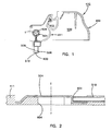
- Figure 1 illustrates a fluid sampler 410 such as that shown in Figures 36-40 of United States Patent 5,823,973 (the '973 patent), the disclosure of which is hereby incorporated herein by reference.
- Figure 2 illustrates a membrane and needle assembly such as that shown in Figure 43 of the '973 patent.
- the present invention will be described to a needle alignment such as that shown in the '973 patent with the axis of the needle parallel to the surface of an absorbing membrane.
- the invention could also be used in other arrangements.
- the needle axis can be perpendicular to the membrane and fluid can flow through the membrane to an opposite side for colormetric testing.
- the sampler 410 has a hollow handle end 409 with an interior 500 to receive a sample end 411.
- the sample end 411 pivots on a pin 502.
- the sample end 411 then can pivot between a storage position within the hollow handle end 409 and a deployed position.
- Figure 1 shows the sample end 411 pivoted into the deployed position.
- the sample end 411 is configured to receive samples such as a fluid.
- An absorbent membrane 504 is carried on the sample end 411.
- the sample end 411 also includes a hub or ferrule 506 that terminates at a ring end 508. In one possible embodiment, the ring end may serve as a pressure ring.
- a needle 510 is held by the ferrule 506. Additionally, the sample end 411 defines a hole 604 (Fig. 2).
- An absorbent membrane 504 has a target area T and is arranged so that the target area T overlies the hole 604.
- the needle 510 includes a hollow, straight tubular body 514, a first or penetration end 600, and a discharge end 601 (shown in Figs. 1 and 2).
- the needle 510 is a 30 gauge needle, about 0.3 mm in outside diameter, although other needle gauges can be used.
- the penetration end 600 protrudes from the ring end 508 of the ferrule by a predetermined distance. The predetermined distance is set so that the first end 600 will penetrate into, but not through, a patient's dermis when the ring 508 is placed against his or her skin.
- the discharge end 601 abuts an absorbent membrane 504 mounted on the sample end 411.
- the longitudinal axis of the needle 510 is perpendicular to the portion of the membrane 504 that forms the target area T.
- the tubular body 514 has an interior surface 511 (Fig. 5) that defines a fluid pathway 512 extending completely through the needle body 514.
- the penetration end 600 of the needle 510 is inserted into the patient's dermis. Fluid then flows along the fluid pathway 512 and through the absorbent membrane 504 to the target area T.
- the absorbent membrane 504 filters out undesirable stray blood cells that may be present in the fluid.
- the fluid at the target area can then be tested for elements such as glucose.
- test the fluid is through the use of infrared light.
- Alternative embodiments include but are not limited to depositing the fluid on a test strip for colormetric testing or on electrodes for electro-chemical testing.
- the needle 510 has a primary beveled face 520 and tip 530 formed at its penetration end 600.
- An entrance hole 521 is formed in the beveled face 520 and is in fluid communication with the fluid path 512.
- the needle 510 also has a front side 522 and an opposite back side 523.
- the tip 530 of the needle 510 is displaced toward the front side 522 of the needle 510.
- one possible way to form the needle 510 is as follows.
- the penetration end 600 of the hollow body 514 is ground at an angle to define the beveled face 520 so that it extends through the body 514 and forms the sharp penetration tip 530.
- the beveled face is formed at an angle ⁇ (about 9°) with respect to a longitudinal axis CL - CL of the needle body 514.
- the formation of a beveled face 520 results in formation of the entrance hole 521 on beveled face 520.
- the present invention is shown with a needle having a single grind forming the beveled face.
- the present invention is also applicable to needles with multiple grinds forming the beveled face.
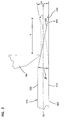
- a fulcrum 700 is placed at a bend location, which is a distance X from the tip 530.
- the distance X is about 1.2 mm, although other distances can be used.
- the tip 530 is then urged toward the front side 522 to permanently displace the tip 530 and form a bend angle ⁇ .
- the tip 530 moves from being aligned with a plane of the back side 523 of the body 514 to a location spaced by a distance Y from the plane of the back side 523.
- This method creates an arcuate bend which is approximated in the Figures by the bend angle ⁇ .
- the bend angle ⁇ is about 27.1°, although other bend angles are possible.
- a displaced tip 530 results in enhanced fluid collection. Possibly, a pocket is formed around the opening 521 to improve fluid flow. Whatever the mechanism, fluid collection is enhanced. Further, the degree of enhancement improves with the amount of deflection Y.
- the following table illustrates the amount of time required to collect an adequate sample (in the test presumed to be about 0.9 ⁇ l of fluid) for an average of needle samples at various tip displacements Y and for a variety of axial locations X (with X and Y as defined with reference to Fig. 3). The amount of time greatly decreases with an increase in Y. In fact, displacement of the tip above the front plane of the needle body has resulted in enhanced collection.
- Figures 5A and 5B illustrate a preferred embodiment where the tip 530" is displaced above the front side 522" of the needle 510".
- elements in common with those of the embodiment of Figs. 3 - 5 are similarly numbered (and need not be separately discussed beyond what follows) with the addition of a double apostrophe to distinguish the embodiments.
- the needle 510" is .012 inch (about .3048 mm or 30 gauge) outside diameter.
- the preferred embodiment was derived following experimentation subsequent to that enumerated in the above table.
- the bend angle ⁇ is the lesser included angle of a straight line A tangent to the bent portion 600" and an extension line B of the straight portion.
- the distance Y is the distance between the tip 530" and the straight line extension B.
- the distance X is the distance from the intersection of the tangent line A and straight line extension B to the tip 530". All of the data in the following table illustrate fluid collection rate (measured in microliters per second, ⁇ l/sec.) as measured using a preferred value of X equal to .035 inch (about .8890 mm).
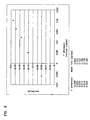
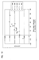
- Figure 9 is a graphical representation of the collection rate ( ⁇ l/sec.) as a function of the Y displacement (where Y is the average Y values for various bend angles ⁇ provided in Table B.
- Figure 10 is a scatter chart of the data plotted as collection rate ( ⁇ l/sec.) as a function of the bend angle ⁇ .
- the fluid in certain applications (for example, collecting interstitial fluid for testing), it is desirable for the fluid to have a low blood content so as to be substantially blood-free.
- substantially blood free it is meant a sample with a hemocrit content of less than 10%.
- the needle 510 is dulled at the penetration end.
- the dulled edges at the penetration end have benefits separate from the displaced tip described above. Specifically, the dulled edges are found to reduce the amount of unwanted blood in a collected sample of interstitial fluid.
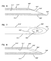
- Figures 6-8 illustrate a needle having a straight tip before and after its edges are dulled. Although the dulled edges are illustrated on a needle having a straight tip, they also could be used in conjunction with a displaced tip as described above. Elements and structures that are in common with the embodiments described above are marked with the same reference numerals with the addition of an apostrophe.
- the beveled face 520' is initially formed by grinding the needle 514' at the penetration end 600' as discussed above to form opening 521' (shown in Fig. 7).
- This grinding forms an outer peripheral edge 630', which is defined by the intersection of the beveled face 520' and the outer surface of the cylindrical body 514'.
- an inner peripheral edge 632' is defined by the intersection of the beveled face 520' and the interior surface 511' of the needle body 514'.
- the inner and outer peripheral edges 630' and 632' and tip 530' are initially sharp (i.e., are formed at substantially non-rounded intersections).
- the inner and outer edges 630' and 632' and tip 530' are dulled so that they become burnished or radiused.
- the dulled edges are formed in a burnishing operation by tumbling the needle 510' in a tumbler with a polishing medium.
- the polishing medium is a fine media such as 1 mm ceramic spheres and a soap solution.
- About 5,000 needles are tumbled in a single batch in the polishing medium for about 20 minutes.
- Other possible tumbling methods use a different polishing medium, different batch sizes, or different lengths of time.
- this process dulls the inner and outer edges 630' and 632' and tip 530'.
- the edges 630' and 632' and tip 530' are dulled to a radius of about 0.002 inch or about 0.05 mm.
- a burnishing process is described herein, manufacturing processes other than tumbling may be used to form the dulled edges.
- the present invention has been described in a preferred embodiment. Modifications and equivalents of such disclosure are intended to be included in the appended claims.
- the benefits of the displaced tip can be attained without the dulled edges of the needle.
- the benefits of the dulled edges can be attained without the displaced tip of the needle.
- all needles have been shown with a single bevel. Nevertheless, the present invention is applicable to a needle with multiple bevels.
Abstract
Description
- This invention pertains to testing a body fluid for an analyte. More specifically, the present invention pertains to a novel needle design in combination with a collection apparatus for collecting a sample of such a fluid.
- Numerous patents teach various ways for collecting a sample of body fluid and testing such fluid for an analyte such as glucose. For example, United States Patents 5,820,570 and 5,823,973 describe methods and apparatus for obtaining, in one embodiment, interstitial fluid which is tested for glucose through IR absorption. These patents also describe use of the disclosed inventions in colormetric and electro-chemical testing of glucose.
- Present development efforts are directed to testing very small volumes of body fluid (e.g. about 0.5 µl). The use of such small volumes of fluid permits less painful collection of a fluid samples. However, small fluid volumes present additional challenges for analyte testing. For example, testing for analytes typically requires a fluid sample in excess of a predetermined minimum volume. By way of non-limiting representative example, a test may require a minimum sample size of about 1 to 5 µl to yield reliable test results.
- The '973 patent shows a small diameter needle (about 28 to 32 gauge or about 0.36 mm to 0.23 mm outside diameter) with a length to penetrate into but not through a dermis to access interstitial fluid contained within the dermis. Preferably, the fluid is blood-free to facilitate subsequent testing of the fluid for analytes such as glucose.
- The use of a small needle dimensioned as described in the '973 patent greatly reduces pain. However, pain may occasionally occur. Further, there is a need for a needle design that enhances the rate at which a sample is collected by such a needle.
- The present invention is directed to an apparatus for collecting a body fluid for testing for an analyte contained within said body fluid. The apparatus comprises a needle for penetrating a patient's skin to access the fluid within said skin. The needle has a hollow body extending from a first end to a second end with a fluid pathway extending between the ends. The second end is positioned to deposit fluid for testing. The first end is configured to penetrate the skin and includes a beveled face on a front side of said body. The beveled face terminates at a penetration tip. The beveled face has an opening in communication with the fluid pathway. The body has a linear axis adjacent the first end. The first end includes a bend formed on the front side of the beveled face to be deflected toward said front side.
-
- Figure 1 is a side elevation view of a needle contained in a sampler;
- Figure 2 is a side sectional view of a needle positioned relative to an absorbent membrane;
- Figure 3 is a side elevation view of a needle being bent;
- Figure 4 is a top plan view of a bent needle;
- Figure 5 is a view taken along line 5 - 5 of Figure 4;
- Figure 5A is an end view of a discharge end of a bent needle;
- Figure 5B is a view taken along
lines 5B - 5B of Figure 5A and providing an enlarged view of a bent tip of the needle of Figure 5 and showing a preferred embodiment with the tip bent above the needle; - Figure 6 is a side sectional view of a tip of a prior art needle;
- Figure 7 is a top plan view of the needle tip shown in Figure 6; and
- Figure 8 is a side elevation view of the needle shown in Figures 6 and 7 following dulling of the needle tip;
- Figure 9 is a graphical representation of a collection rate as a function of needle tip displacement for a needle such as that shown in Figs. 5A and 5B; and
- Figure 10 is a scatter chart of a collection rate as a function of the bend angle of a needle tip for a needle such as that shown in Figs. 5A and 5B.
-
- Various embodiments of the present invention, including a preferred embodiment, will be described in detail with reference to the drawings wherein like reference numerals represent like parts and assemblies throughout the several views. Reference to the described embodiments does not limit the scope of the invention, which is limited only by the scope of the appended claims.
- Throughout the following description, an embodiment of the present invention will be described with reference to collecting a sample of interstitial fluid for glucose testing using a narrow needle that penetrates into, but not through, the dermis. Such sample collection is more fully described in commonly assigned United States Patents 5,823,973 and 5,820,570, the disclosures for both of which are hereby incorporated by reference as though set forth in full. While such a use is a preferred embodiment, the present invention is applicable to other fluid collection systems as well as testing for other fluid analytes.
- Figure 1 illustrates a
fluid sampler 410 such as that shown in Figures 36-40 of United States Patent 5,823,973 (the '973 patent), the disclosure of which is hereby incorporated herein by reference. Figure 2 illustrates a membrane and needle assembly such as that shown in Figure 43 of the '973 patent. For ease of illustration, the present invention will be described to a needle alignment such as that shown in the '973 patent with the axis of the needle parallel to the surface of an absorbing membrane. The invention could also be used in other arrangements. For example, the needle axis can be perpendicular to the membrane and fluid can flow through the membrane to an opposite side for colormetric testing. - Referring now to Figures 1 and 2, the
sampler 410 has ahollow handle end 409 with an interior 500 to receive asample end 411. The sample end 411 pivots on apin 502. Thesample end 411 then can pivot between a storage position within thehollow handle end 409 and a deployed position. Figure 1 shows thesample end 411 pivoted into the deployed position. - The
sample end 411 is configured to receive samples such as a fluid. Anabsorbent membrane 504 is carried on thesample end 411. Thesample end 411 also includes a hub orferrule 506 that terminates at aring end 508. In one possible embodiment, the ring end may serve as a pressure ring. Aneedle 510 is held by theferrule 506. Additionally, thesample end 411 defines a hole 604 (Fig. 2). Anabsorbent membrane 504 has a target area T and is arranged so that the target area T overlies thehole 604. - As shown in Fig. 3, the
needle 510 includes a hollow, straighttubular body 514, a first orpenetration end 600, and a discharge end 601 (shown in Figs. 1 and 2). In one embodiment, theneedle 510 is a 30 gauge needle, about 0.3 mm in outside diameter, although other needle gauges can be used. In a preferred embodiment, thepenetration end 600 protrudes from thering end 508 of the ferrule by a predetermined distance. The predetermined distance is set so that thefirst end 600 will penetrate into, but not through, a patient's dermis when thering 508 is placed against his or her skin. - The
discharge end 601 abuts anabsorbent membrane 504 mounted on thesample end 411. In this configuration, the longitudinal axis of theneedle 510 is perpendicular to the portion of themembrane 504 that forms the target area T. Additionally, thetubular body 514 has an interior surface 511 (Fig. 5) that defines afluid pathway 512 extending completely through theneedle body 514. - In use, the
penetration end 600 of theneedle 510 is inserted into the patient's dermis. Fluid then flows along thefluid pathway 512 and through theabsorbent membrane 504 to the target area T. Theabsorbent membrane 504 filters out undesirable stray blood cells that may be present in the fluid. The fluid at the target area can then be tested for elements such as glucose. - One possible way to test the fluid is through the use of infrared light. Alternative embodiments include but are not limited to depositing the fluid on a test strip for colormetric testing or on electrodes for electro-chemical testing.
- Referring to Figures 4 and 5, the
needle 510 has a primarybeveled face 520 andtip 530 formed at itspenetration end 600. Anentrance hole 521 is formed in thebeveled face 520 and is in fluid communication with thefluid path 512. Theneedle 510 also has afront side 522 and an oppositeback side 523. Thetip 530 of theneedle 510 is displaced toward thefront side 522 of theneedle 510. - Referring to Figure 3, one possible way to form the
needle 510 is as follows. Thepenetration end 600 of thehollow body 514 is ground at an angle to define thebeveled face 520 so that it extends through thebody 514 and forms thesharp penetration tip 530. In one possible embodiment, the beveled face is formed at an angle β (about 9°) with respect to a longitudinal axis CL - CL of theneedle body 514. The formation of abeveled face 520 results in formation of theentrance hole 521 onbeveled face 520. The present invention is shown with a needle having a single grind forming the beveled face. The present invention is also applicable to needles with multiple grinds forming the beveled face. - After providing a
needle body 514 with a flatbeveled face 520, afulcrum 700 is placed at a bend location, which is a distance X from thetip 530. In one possible embodiment, the distance X is about 1.2 mm, although other distances can be used. Thetip 530 is then urged toward thefront side 522 to permanently displace thetip 530 and form a bend angle α. When thetip 530 is displaced, it moves from being aligned with a plane of theback side 523 of thebody 514 to a location spaced by a distance Y from the plane of theback side 523. This method creates an arcuate bend which is approximated in the Figures by the bend angle α. In one possible embodiment, the bend angle α is about 27.1°, although other bend angles are possible. - For reasons not fully understood, the use of a displaced
tip 530 results in enhanced fluid collection. Possibly, a pocket is formed around theopening 521 to improve fluid flow. Whatever the mechanism, fluid collection is enhanced. Further, the degree of enhancement improves with the amount of deflection Y. The following table illustrates the amount of time required to collect an adequate sample (in the test presumed to be about 0.9 µl of fluid) for an average of needle samples at various tip displacements Y and for a variety of axial locations X (with X and Y as defined with reference to Fig. 3). The amount of time greatly decreases with an increase in Y. In fact, displacement of the tip above the front plane of the needle body has resulted in enhanced collection. In the following table, negative values of α and Y reflect a backward bending of the tip behind the rear side of the needle. Zero values reflect an unbent needle.Time to Collect Pre-determined Amount of Sample Location X (mm) Angle α (degrees) Displacement Y (mm) Time to Collect .9 µl of Sample (seconds) 1.07 -6.03 -0.14 26.75 0 0 0 15.51 0.88 3.24 0.09 12.75 1.57 5.71 0.13 10.41 0.86 11.3 0.15 11.46 2.03 8.13 0.25 12.74 1.30 12.8 0.279 9.04 0.59 28.3 0.281 7.63 1.68 13.7 0.38 7.96 0.94 25.9 0.43 6.62 1.41 21.6 0.51 5.66 - Figures 5A and 5B illustrate a preferred embodiment where the
tip 530" is displaced above thefront side 522" of theneedle 510". In Figs. 5A and 5B, elements in common with those of the embodiment of Figs. 3 - 5 are similarly numbered (and need not be separately discussed beyond what follows) with the addition of a double apostrophe to distinguish the embodiments. - The
needle 510" is .012 inch (about .3048 mm or 30 gauge) outside diameter. The preferred embodiment was derived following experimentation subsequent to that enumerated in the above table. In Figure 5B, the bend angle is the lesser included angle of a straight line A tangent to thebent portion 600" and an extension line B of the straight portion. The distance Y is the distance between thetip 530" and the straight line extension B. The distance X is the distance from the intersection of the tangent line A and straight line extension B to thetip 530". All of the data in the following table illustrate fluid collection rate (measured in microliters per second, µl/sec.) as measured using a preferred value of X equal to .035 inch (about .8890 mm). The negative values for and Y represent a downward bend. Positive values represent upward bends as illustrated in Figure 5B. A zero value represents an unbent needle.Fluid Collection Rate (Micro-Liters/Second) VALUES of Y Bend Angle () in degrees -.006 inch
(≅.1524 mm).000 inch
(≅.0000 mm).005 inch
(≅.1270 mm).012 inch
(≅.3048 mm).016 inch
(≅.4064 mm).020 inch
(≅.5080 mm)-8.1 0.06 0.0 0.10 4.6 0.13 6.5 0.13 7.1 0.12 7.6 0.10 10.0 0.14 12.2 0.15 12.2 0.13 12.8 0.16 14.9 0.13 16.8 0.13 20.0 0.19 21.6 0.17 21.8 0.16 24.7 0.19 25.6 0.18 26.6 0.15 31.2 0.20 46.4 0.20 - Using the above data, Figure 9 is a graphical representation of the collection rate (µl/sec.) as a function of the Y displacement (where Y is the average Y values for various bend angles provided in Table B. Figure 10 is a scatter chart of the data plotted as collection rate (µl/sec.) as a function of the bend angle .
- The above data show for a small gauge needle, collection rate improves with increases in both the bend angle and the displacement Y. In fact, displacements greater than the needle's outside diameter of .012 inch (representing a bending of the
tip 530" above thefront side 522" of theneedle 510") shows improved collection rates. - Since pain avoidance is a desirable feature, patients selected to collect the above data were asked to compare pain sensation using the above-configured needles. While pain is subjective, it was surprising to note the patient population did not record appreciable increase in pain until the bend angle exceeded 30°-- 40°. The data suggest optimum design of a low pain needle for maximizing fluid collection rates is to provide a bend angle of about 30° and preferably between 20° and 40° with the
tip 530" of the needle bent above the plane of theneedle 510". - In certain applications (for example, collecting interstitial fluid for testing), it is desirable for the fluid to have a low blood content so as to be substantially blood-free. By substantially blood free, it is meant a sample with a hemocrit content of less than 10%. Using the
bent needle 510" as described, the frequency of occurrence of blood in a sample increases compared to a straight needle, but the samples continue to be substantially blood free. Thepresent needle 510" can also be used to collect higher blood content samples. In both, the design as described increases flow rate while retaining a low pain quality. - In addition to the bend angle described above, the
needle 510 is dulled at the penetration end. The dulled edges at the penetration end have benefits separate from the displaced tip described above. Specifically, the dulled edges are found to reduce the amount of unwanted blood in a collected sample of interstitial fluid. - Figures 6-8, illustrate a needle having a straight tip before and after its edges are dulled. Although the dulled edges are illustrated on a needle having a straight tip, they also could be used in conjunction with a displaced tip as described above. Elements and structures that are in common with the embodiments described above are marked with the same reference numerals with the addition of an apostrophe.
- Referring now to Figures 6 and 7, the beveled face 520' is initially formed by grinding the needle 514' at the penetration end 600' as discussed above to form opening 521' (shown in Fig. 7). This grinding forms an outer peripheral edge 630', which is defined by the intersection of the beveled face 520' and the outer surface of the cylindrical body 514'. Additionally, an inner peripheral edge 632' is defined by the intersection of the beveled face 520' and the interior surface 511' of the needle body 514'. Upon grinding the needle to form the beveled face 520', the inner and outer peripheral edges 630' and 632' and tip 530' are initially sharp (i.e., are formed at substantially non-rounded intersections).
- After the beveled face 520' is formed, the inner and outer edges 630' and 632' and tip 530' are dulled so that they become burnished or radiused. The dulled edges are formed in a burnishing operation by tumbling the needle 510' in a tumbler with a polishing medium. In one possible embodiment, the polishing medium is a fine media such as 1 mm ceramic spheres and a soap solution. About 5,000 needles are tumbled in a single batch in the polishing medium for about 20 minutes. Other possible tumbling methods use a different polishing medium, different batch sizes, or different lengths of time.
- Referring to Figure 8, this process dulls the inner and outer edges 630' and 632' and tip 530'. In one possible embodiment, the edges 630' and 632' and tip 530' are dulled to a radius of about 0.002 inch or about 0.05 mm. Although a burnishing process is described herein, manufacturing processes other than tumbling may be used to form the dulled edges.
- From the foregoing detailed description, the present invention has been described in a preferred embodiment. Modifications and equivalents of such disclosure are intended to be included in the appended claims. For example, the benefits of the displaced tip can be attained without the dulled edges of the needle. Similarly, the benefits of the dulled edges can be attained without the displaced tip of the needle. Additionally, all needles have been shown with a single bevel. Nevertheless, the present invention is applicable to a needle with multiple bevels.
Claims (16)
- An apparatus for collecting a body fluid for testing for an analyte contained within said body fluid, said apparatus comprising:said needle having a hollow body extending from a first end to a second end with a fluid pathway extending between said ends;a needle for penetrating a patient's skin to access said fluid within said skin;
said second end positioned to deposit fluid for subsequent testing;
said first end configured to penetrate said skin and including a beveled face on a front side of said body with said beveled face terminating at a penetration tip with said beveled face having an opening in communication with said fluid pathway; said body having a linear axis adjacent said first end;
characterised in that said first end includes a bend formed on said front side, and in that at least a forward portion of said beveled face is deflected toward said front side with said tip disposed above said axis. - An apparatus according to claim 1 wherein said bend is positioned above said beveled face.
- An apparatus according to claim 1 wherein said beveled face is deflected for said penetration tip to be positioned protruding beyond a plane of said body at said front side.
- An apparatus according to claim 1 wherein:said beveled face extends through a transverse dimension of said body for said penetration tip to define a point on a back side of said body;said bend positioned at a location on said beveled face for said tip to be displaced from said back side and toward said front side.
- An apparatus according to claim 4 wherein said body is substantially tubular and said beveled face is a flat surface at an angle to said body prior to said bend.
- An apparatus according to claim 1 wherein an interior surface of said body defines said fluid pathway, said apparatus further comprising:said beveled face intersecting with an exterior surface of said body to define an outer peripheral edge and said beveled face intersecting with said interior surface to define an inner peripheral edge defining said opening; said outer peripheral edge shaped to present a rounded edge.
- An apparatus according to claim 6 wherein said inner peripheral edge is shaped to present a rounded edge.
- An apparatus according to claim 1 wherein the needle is restrained for the tip to penetrate into and not through the dermis.
- An apparatus according to claim 1 wherein said first end is set at an angle to said axis between about 20° and 40°.
- An apparatus according to claim 1 wherein said first end is set at an angle to said axis of about 30°.
- An apparatus according to claim 1 wherein said hollow body includes an exterior surface defining a plane in which said linear axis lies wherein said penetration tip protrudes laterally beyond said exterior surface of said hollow body on said front side.
- An apparatus according to claims 1 wherein said body ins substantially tubular and said beveled face comprises a substantially flat surface.
- An apparatus according to claim 1 wherein an interior surface of said body defines said fluid pathway, said apparatus further comprising:said beveled face intersecting with said exterior surface of said hollow body to define an outer peripheral edge and said beveled face intersecting with said interior surface to define an inner peripheral edge defining said opening; and said outer peripheral edge having a dulled configuration.
- An apparatus according to claim 13 wherein said inner peripheral edge has a dulled configuration.
- An apparatus according to claim 1 wherein said hollow body defines a central axis and said first end forms an angle with said central axis between about 20° and 40°.
- An apparatus according to claim 15 wherein said first end forms an angle with said central axis of about 30°.
Applications Claiming Priority (5)
| Application Number | Priority Date | Filing Date | Title |
|---|---|---|---|
| US244952 | 1988-09-15 | ||
| US24495299A | 1999-02-04 | 1999-02-04 | |
| US427161 | 1999-10-26 | ||
| US09/427,161 US6702791B1 (en) | 1999-02-04 | 1999-10-26 | Needle for body fluid tester |
| EP00913272A EP1148820B1 (en) | 1999-02-04 | 2000-01-26 | Needle for body fluid tester |
Related Parent Applications (2)
| Application Number | Title | Priority Date | Filing Date |
|---|---|---|---|
| EP00913272.1 Division | 2000-01-26 | ||
| EP00913272A Division EP1148820B1 (en) | 1999-02-04 | 2000-01-26 | Needle for body fluid tester |
Publications (2)
| Publication Number | Publication Date |
|---|---|
| EP1579808A1 true EP1579808A1 (en) | 2005-09-28 |
| EP1579808B1 EP1579808B1 (en) | 2010-12-08 |
Family
ID=26936915
Family Applications (2)
| Application Number | Title | Priority Date | Filing Date |
|---|---|---|---|
| EP00913272A Expired - Lifetime EP1148820B1 (en) | 1999-02-04 | 2000-01-26 | Needle for body fluid tester |
| EP05075625A Expired - Lifetime EP1579808B1 (en) | 1999-02-04 | 2000-01-26 | Needle for body fluid tester |
Family Applications Before (1)
| Application Number | Title | Priority Date | Filing Date |
|---|---|---|---|
| EP00913272A Expired - Lifetime EP1148820B1 (en) | 1999-02-04 | 2000-01-26 | Needle for body fluid tester |
Country Status (12)
| Country | Link |
|---|---|
| US (2) | US6802199B2 (en) |
| EP (2) | EP1148820B1 (en) |
| JP (1) | JP2002536042A (en) |
| AT (2) | ATE290821T1 (en) |
| AU (1) | AU768000B2 (en) |
| CA (1) | CA2361062A1 (en) |
| DE (2) | DE60045351D1 (en) |
| DK (1) | DK1148820T3 (en) |
| ES (1) | ES2235842T3 (en) |
| HK (1) | HK1078250A1 (en) |
| PT (1) | PT1148820E (en) |
| WO (1) | WO2000045708A1 (en) |
Families Citing this family (109)
| Publication number | Priority date | Publication date | Assignee | Title |
|---|---|---|---|---|
| US7828749B2 (en) | 1996-05-17 | 2010-11-09 | Roche Diagnostics Operations, Inc. | Blood and interstitial fluid sampling device |
| EP1579814A3 (en) | 1996-05-17 | 2006-06-14 | Roche Diagnostics Operations, Inc. | Methods and apparatus for sampling and analyzing body fluid |
| US20020010406A1 (en) | 1996-05-17 | 2002-01-24 | Douglas Joel S. | Methods and apparatus for expressing body fluid from an incision |
| US7235056B2 (en) | 1996-05-17 | 2007-06-26 | Amira Medical | Body fluid sampling device and methods of use |
| US6036924A (en) | 1997-12-04 | 2000-03-14 | Hewlett-Packard Company | Cassette of lancet cartridges for sampling blood |
| US6391005B1 (en) | 1998-03-30 | 2002-05-21 | Agilent Technologies, Inc. | Apparatus and method for penetration with shaft having a sensor for sensing penetration depth |
| US6702791B1 (en) | 1999-02-04 | 2004-03-09 | Integ, Inc. | Needle for body fluid tester |
| US9603741B2 (en) | 2000-05-19 | 2017-03-28 | Michael S. Berlin | Delivery system and method of use for the eye |
| US8641644B2 (en) | 2000-11-21 | 2014-02-04 | Sanofi-Aventis Deutschland Gmbh | Blood testing apparatus having a rotatable cartridge with multiple lancing elements and testing means |
| JP2004532695A (en) * | 2001-06-08 | 2004-10-28 | エフ ホフマン−ラ ロッシュ アクチェン ゲゼルシャフト | Apparatus and method for sampling body fluid |
| US7749174B2 (en) | 2001-06-12 | 2010-07-06 | Pelikan Technologies, Inc. | Method and apparatus for lancet launching device intergrated onto a blood-sampling cartridge |
| US9226699B2 (en) | 2002-04-19 | 2016-01-05 | Sanofi-Aventis Deutschland Gmbh | Body fluid sampling module with a continuous compression tissue interface surface |
| US7699791B2 (en) | 2001-06-12 | 2010-04-20 | Pelikan Technologies, Inc. | Method and apparatus for improving success rate of blood yield from a fingerstick |
| US8337419B2 (en) | 2002-04-19 | 2012-12-25 | Sanofi-Aventis Deutschland Gmbh | Tissue penetration device |
| US6837988B2 (en) | 2001-06-12 | 2005-01-04 | Lifescan, Inc. | Biological fluid sampling and analyte measurement devices and methods |
| US7033371B2 (en) | 2001-06-12 | 2006-04-25 | Pelikan Technologies, Inc. | Electric lancet actuator |
| US6793632B2 (en) | 2001-06-12 | 2004-09-21 | Lifescan, Inc. | Percutaneous biological fluid constituent sampling and measurement devices and methods |
| US7041068B2 (en) | 2001-06-12 | 2006-05-09 | Pelikan Technologies, Inc. | Sampling module device and method |
| DE60234597D1 (en) | 2001-06-12 | 2010-01-14 | Pelikan Technologies Inc | DEVICE AND METHOD FOR REMOVING BLOOD SAMPLES |
| US6501976B1 (en) | 2001-06-12 | 2002-12-31 | Lifescan, Inc. | Percutaneous biological fluid sampling and analyte measurement devices and methods |
| US6875613B2 (en) | 2001-06-12 | 2005-04-05 | Lifescan, Inc. | Biological fluid constituent sampling and measurement devices and methods |
| US7981056B2 (en) | 2002-04-19 | 2011-07-19 | Pelikan Technologies, Inc. | Methods and apparatus for lancet actuation |
| US7344507B2 (en) | 2002-04-19 | 2008-03-18 | Pelikan Technologies, Inc. | Method and apparatus for lancet actuation |
| US9427532B2 (en) | 2001-06-12 | 2016-08-30 | Sanofi-Aventis Deutschland Gmbh | Tissue penetration device |
| US9795747B2 (en) | 2010-06-02 | 2017-10-24 | Sanofi-Aventis Deutschland Gmbh | Methods and apparatus for lancet actuation |
| CA2448902C (en) | 2001-06-12 | 2010-09-07 | Pelikan Technologies, Inc. | Self optimizing lancing device with adaptation means to temporal variations in cutaneous properties |
| US6721586B2 (en) | 2001-06-12 | 2004-04-13 | Lifescan, Inc. | Percutaneous biological fluid sampling and analyte measurement devices and methods |
| US20040267160A9 (en) | 2001-09-26 | 2004-12-30 | Edward Perez | Method and apparatus for sampling bodily fluid |
| US7331931B2 (en) | 2002-04-19 | 2008-02-19 | Pelikan Technologies, Inc. | Method and apparatus for penetrating tissue |
| US8221334B2 (en) | 2002-04-19 | 2012-07-17 | Sanofi-Aventis Deutschland Gmbh | Method and apparatus for penetrating tissue |
| US7371247B2 (en) | 2002-04-19 | 2008-05-13 | Pelikan Technologies, Inc | Method and apparatus for penetrating tissue |
| US7291117B2 (en) | 2002-04-19 | 2007-11-06 | Pelikan Technologies, Inc. | Method and apparatus for penetrating tissue |
| US7892183B2 (en) | 2002-04-19 | 2011-02-22 | Pelikan Technologies, Inc. | Method and apparatus for body fluid sampling and analyte sensing |
| US7976476B2 (en) | 2002-04-19 | 2011-07-12 | Pelikan Technologies, Inc. | Device and method for variable speed lancet |
| US7901362B2 (en) | 2002-04-19 | 2011-03-08 | Pelikan Technologies, Inc. | Method and apparatus for penetrating tissue |
| US7232451B2 (en) | 2002-04-19 | 2007-06-19 | Pelikan Technologies, Inc. | Method and apparatus for penetrating tissue |
| US7648468B2 (en) | 2002-04-19 | 2010-01-19 | Pelikon Technologies, Inc. | Method and apparatus for penetrating tissue |
| US7229458B2 (en) | 2002-04-19 | 2007-06-12 | Pelikan Technologies, Inc. | Method and apparatus for penetrating tissue |
| US8784335B2 (en) | 2002-04-19 | 2014-07-22 | Sanofi-Aventis Deutschland Gmbh | Body fluid sampling device with a capacitive sensor |
| US8702624B2 (en) | 2006-09-29 | 2014-04-22 | Sanofi-Aventis Deutschland Gmbh | Analyte measurement device with a single shot actuator |
| US7491178B2 (en) | 2002-04-19 | 2009-02-17 | Pelikan Technologies, Inc. | Method and apparatus for penetrating tissue |
| US8267870B2 (en) | 2002-04-19 | 2012-09-18 | Sanofi-Aventis Deutschland Gmbh | Method and apparatus for body fluid sampling with hybrid actuation |
| US9248267B2 (en) | 2002-04-19 | 2016-02-02 | Sanofi-Aventis Deustchland Gmbh | Tissue penetration device |
| US8372016B2 (en) | 2002-04-19 | 2013-02-12 | Sanofi-Aventis Deutschland Gmbh | Method and apparatus for body fluid sampling and analyte sensing |
| US8360992B2 (en) | 2002-04-19 | 2013-01-29 | Sanofi-Aventis Deutschland Gmbh | Method and apparatus for penetrating tissue |
| US7297122B2 (en) | 2002-04-19 | 2007-11-20 | Pelikan Technologies, Inc. | Method and apparatus for penetrating tissue |
| US7717863B2 (en) | 2002-04-19 | 2010-05-18 | Pelikan Technologies, Inc. | Method and apparatus for penetrating tissue |
| US7909778B2 (en) | 2002-04-19 | 2011-03-22 | Pelikan Technologies, Inc. | Method and apparatus for penetrating tissue |
| US8579831B2 (en) | 2002-04-19 | 2013-11-12 | Sanofi-Aventis Deutschland Gmbh | Method and apparatus for penetrating tissue |
| US9795334B2 (en) | 2002-04-19 | 2017-10-24 | Sanofi-Aventis Deutschland Gmbh | Method and apparatus for penetrating tissue |
| US7547287B2 (en) | 2002-04-19 | 2009-06-16 | Pelikan Technologies, Inc. | Method and apparatus for penetrating tissue |
| US7674232B2 (en) | 2002-04-19 | 2010-03-09 | Pelikan Technologies, Inc. | Method and apparatus for penetrating tissue |
| US7226461B2 (en) | 2002-04-19 | 2007-06-05 | Pelikan Technologies, Inc. | Method and apparatus for a multi-use body fluid sampling device with sterility barrier release |
| US9314194B2 (en) | 2002-04-19 | 2016-04-19 | Sanofi-Aventis Deutschland Gmbh | Tissue penetration device |
| US20050049522A1 (en) * | 2002-10-30 | 2005-03-03 | Allen John J | Method of lancing skin for the extraction of blood |
| US8574895B2 (en) | 2002-12-30 | 2013-11-05 | Sanofi-Aventis Deutschland Gmbh | Method and apparatus using optical techniques to measure analyte levels |
| US7473264B2 (en) * | 2003-03-28 | 2009-01-06 | Lifescan, Inc. | Integrated lance and strip for analyte measurement |
| US20040193072A1 (en) * | 2003-03-28 | 2004-09-30 | Allen John J. | Method of analyte measurement using integrated lance and strip |
| ES2347248T3 (en) | 2003-05-30 | 2010-10-27 | Pelikan Technologies Inc. | PROCEDURE AND APPLIANCE FOR FLUID INJECTION. |
| WO2004107964A2 (en) | 2003-06-06 | 2004-12-16 | Pelikan Technologies, Inc. | Blood harvesting device with electronic control |
| US20040253736A1 (en) * | 2003-06-06 | 2004-12-16 | Phil Stout | Analytical device with prediction module and related methods |
| US7258673B2 (en) * | 2003-06-06 | 2007-08-21 | Lifescan, Inc | Devices, systems and methods for extracting bodily fluid and monitoring an analyte therein |
| US20040249254A1 (en) * | 2003-06-06 | 2004-12-09 | Joel Racchini | Devices, systems and methods for extracting bodily fluid and monitoring an analyte therein |
| WO2006001797A1 (en) | 2004-06-14 | 2006-01-05 | Pelikan Technologies, Inc. | Low pain penetrating |
| WO2005033659A2 (en) | 2003-09-29 | 2005-04-14 | Pelikan Technologies, Inc. | Method and apparatus for an improved sample capture device |
| US9351680B2 (en) | 2003-10-14 | 2016-05-31 | Sanofi-Aventis Deutschland Gmbh | Method and apparatus for a variable user interface |
| US20050113739A1 (en) * | 2003-11-21 | 2005-05-26 | Matthias Stiene | Device and method for extracting body fluid |
| US7822454B1 (en) | 2005-01-03 | 2010-10-26 | Pelikan Technologies, Inc. | Fluid sampling device with improved analyte detecting member configuration |
| EP1706026B1 (en) | 2003-12-31 | 2017-03-01 | Sanofi-Aventis Deutschland GmbH | Method and apparatus for improving fluidic flow and sample capture |
| US20050187525A1 (en) * | 2004-02-19 | 2005-08-25 | Hilgers Michael E. | Devices and methods for extracting bodily fluid |
| US6990849B2 (en) | 2004-03-26 | 2006-01-31 | Lifescan, Inc. | Microfluidic analytical system with position electrodes |
| US20050266571A1 (en) * | 2004-03-26 | 2005-12-01 | Phil Stout | Method for feedback control of a microfluidic system |
| US20060013731A1 (en) * | 2004-03-26 | 2006-01-19 | Phil Stout | Microfluidic system with feedback control |
| US8828203B2 (en) | 2004-05-20 | 2014-09-09 | Sanofi-Aventis Deutschland Gmbh | Printable hydrogels for biosensors |
| US9775553B2 (en) | 2004-06-03 | 2017-10-03 | Sanofi-Aventis Deutschland Gmbh | Method and apparatus for a fluid sampling device |
| US9820684B2 (en) | 2004-06-03 | 2017-11-21 | Sanofi-Aventis Deutschland Gmbh | Method and apparatus for a fluid sampling device |
| US20050284773A1 (en) * | 2004-06-29 | 2005-12-29 | Allen John J | Method of preventing reuse in an analyte measuring system |
| US20060036187A1 (en) | 2004-06-30 | 2006-02-16 | Hester Vos | Devices, systems and methods for extracting bodily fluid and monitoring an analyte therein |
| WO2006026741A1 (en) * | 2004-08-31 | 2006-03-09 | Lifescan Scotland Limited | Wearable sensor device and system |
| US8652831B2 (en) | 2004-12-30 | 2014-02-18 | Sanofi-Aventis Deutschland Gmbh | Method and apparatus for analyte measurement test time |
| US20070038147A1 (en) | 2005-08-11 | 2007-02-15 | Joel Mechelke | Method for extracting interstitial fluid |
| US20090082862A1 (en) | 2007-09-24 | 2009-03-26 | Schieber Andrew T | Ocular Implant Architectures |
| US8734377B2 (en) | 2007-09-24 | 2014-05-27 | Ivantis, Inc. | Ocular implants with asymmetric flexibility |
| US20170360609A9 (en) | 2007-09-24 | 2017-12-21 | Ivantis, Inc. | Methods and devices for increasing aqueous humor outflow |
| US8808222B2 (en) * | 2007-11-20 | 2014-08-19 | Ivantis, Inc. | Methods and apparatus for delivering ocular implants into the eye |
| WO2009091990A1 (en) | 2008-01-18 | 2009-07-23 | Ev3 Inc . | Angled tip catheter |
| AU2009221859B2 (en) | 2008-03-05 | 2013-04-18 | Alcon Inc. | Methods and apparatus for treating glaucoma |
| WO2009126900A1 (en) | 2008-04-11 | 2009-10-15 | Pelikan Technologies, Inc. | Method and apparatus for analyte detecting device |
| US9375169B2 (en) | 2009-01-30 | 2016-06-28 | Sanofi-Aventis Deutschland Gmbh | Cam drive for managing disposable penetrating member actions with a single motor and motor and control system |
| CN102481404B (en) | 2009-07-09 | 2014-03-05 | 伊万提斯公司 | Ocular implants |
| AU2010271274B2 (en) | 2009-07-09 | 2015-05-21 | Alcon Inc. | Single operator device for delivering an ocular implant |
| JP2013508096A (en) | 2009-10-23 | 2013-03-07 | イバンティス インコーポレイテッド | Intraocular transplantation system and intraocular transplantation method |
| US8965476B2 (en) | 2010-04-16 | 2015-02-24 | Sanofi-Aventis Deutschland Gmbh | Tissue penetration device |
| US20110295152A1 (en) * | 2010-05-25 | 2011-12-01 | Nextier Corporation | Puncture method, incision needle, puncture needle, needle cap and instrument for blood purification treatment |
| WO2011163505A1 (en) | 2010-06-23 | 2011-12-29 | Ivantis, Inc. | Ocular implants deployed in schlemm's canal of the eye |
| TW201216924A (en) * | 2010-07-08 | 2012-05-01 | Sanofi Aventis Deutschland | Apparatus including a lancet |
| TW201206400A (en) | 2010-07-08 | 2012-02-16 | Sanofi Aventis Deutschland | Allowing measurements to be made of a blood sample |
| US8657776B2 (en) | 2011-06-14 | 2014-02-25 | Ivantis, Inc. | Ocular implants for delivery into the eye |
| US8663150B2 (en) | 2011-12-19 | 2014-03-04 | Ivantis, Inc. | Delivering ocular implants into the eye |
| US9358156B2 (en) | 2012-04-18 | 2016-06-07 | Invantis, Inc. | Ocular implants for delivery into an anterior chamber of the eye |
| US10617558B2 (en) | 2012-11-28 | 2020-04-14 | Ivantis, Inc. | Apparatus for delivering ocular implants into an anterior chamber of the eye |
| WO2016011056A1 (en) | 2014-07-14 | 2016-01-21 | Ivantis, Inc. | Ocular implant delivery system and method |
| KR101626053B1 (en) * | 2014-09-19 | 2016-06-01 | 연세대학교 산학협력단 | One-touch Device for Extracting Body Fluid |
| MX2017010466A (en) | 2015-02-17 | 2018-06-06 | Amgen Inc | Drug delivery device with vacuum assisted securement and/or feedback. |
| CN108135470B (en) | 2015-08-14 | 2021-03-09 | 伊万提斯公司 | Ocular implant with pressure sensor and delivery system |
| US11109785B2 (en) * | 2015-09-24 | 2021-09-07 | Becton, Dickinson And Company | Five-bevel cannula for blood acquisition devices |
| WO2017106517A1 (en) | 2015-12-15 | 2017-06-22 | Ivantis, Inc. | Ocular implant and delivery system |
| CA3166003A1 (en) * | 2020-01-23 | 2021-07-29 | Sureax, Inc. | Needle devices for accessing lymph nodes and thoracic ducts |
| EP4274529A1 (en) | 2021-01-11 | 2023-11-15 | Alcon Inc. | Systems and methods for viscoelastic delivery |
Citations (5)
| Publication number | Priority date | Publication date | Assignee | Title |
|---|---|---|---|---|
| US4368738A (en) * | 1980-04-05 | 1983-01-18 | Bernd Tersteegen | Cannula |
| US4889529A (en) * | 1987-07-10 | 1989-12-26 | B. Braun Melsungen Ag | Needle |
| EP0739639A1 (en) * | 1995-04-28 | 1996-10-30 | Yoshikuni Saito | A medical hollow needle and a method of producing thereof |
| US5820570A (en) | 1993-10-13 | 1998-10-13 | Integ Incorporated | Interstitial fluid collection and constituent measurement |
| US5823973A (en) | 1995-09-08 | 1998-10-20 | Integ, Inc. | Needle assembly for fluid sampler |
Family Cites Families (25)
| Publication number | Priority date | Publication date | Assignee | Title |
|---|---|---|---|---|
| US2409979A (en) * | 1946-03-14 | 1946-10-22 | Ralph L Huber | Hypodermic needle |
| US2717599A (en) | 1952-02-18 | 1955-09-13 | Huber Jennie | Needle structure |
| US2748769A (en) | 1953-02-24 | 1956-06-05 | Huber Jennie | Hypodermic needle |
| US2697438A (en) | 1953-10-16 | 1954-12-21 | Bishop & Co Platinum Works J | Noncoring hypodermic needle |
| US3872806A (en) | 1973-02-15 | 1975-03-25 | Dennison Mfg Co | Fastener attachment insertion device needle construction |
| IT998674B (en) | 1973-09-28 | 1976-02-20 | Orinospital Spa | PERFECTED SUCTION AND INFUSION NEEDLE |
| US3906932A (en) | 1974-02-27 | 1975-09-23 | Becton Dickinson Co | Needle point for stopper penetration and method of making it |
| US4441373A (en) * | 1979-02-21 | 1984-04-10 | American Hospital Supply Corporation | Collection tube for drawing samples of biological fluids |
| US4383530A (en) | 1981-06-05 | 1983-05-17 | John Bruno | Hypodermic needle and method of making needles |
| DE3327585A1 (en) * | 1982-08-06 | 1984-02-09 | John Martin Oxford Evans | SURGICAL INSTRUMENT FOR EPIDURAL AND SPINAL ANESTHESIA |
| US4490139A (en) | 1983-01-28 | 1984-12-25 | Eli Lilly And Company | Implant needle and method |
| US4808170A (en) | 1985-12-16 | 1989-02-28 | Alcon Laboratories, Inc. | Hypotraumatic injection needle useful in ophthalmic surgery |
| US4799494A (en) | 1986-10-22 | 1989-01-24 | Wang Ko P | Percutaneous aspiration lung biopsy needle assembly |
| US4788986A (en) | 1987-03-16 | 1988-12-06 | Harris Jim C | Holder for blood collecting needle |
| US4753641A (en) | 1987-09-10 | 1988-06-28 | Vaslow Dale F | Emergency medical needle |
| DE3915215A1 (en) | 1989-05-05 | 1990-11-08 | Moehring Klaus | DEVICE FOR INTRODUCING LONG-STRETCHED OBJECTS INTO HUMAN OR ANIMAL BODIES OR ORGANS |
| US5295980A (en) | 1989-10-30 | 1994-03-22 | Ersek Robert A | Multi-use cannula system |
| US5505694A (en) | 1990-08-22 | 1996-04-09 | Tcnl Technologies, Inc. | Apparatus and method for raising a skin wheal |
| US5290267A (en) * | 1991-01-17 | 1994-03-01 | Fresenius Ag | Hypodermic needle |
| US5607401A (en) | 1991-09-03 | 1997-03-04 | Humphrey; Bruce H. | Augmented polymeric hypodermic devices |
| AU2498295A (en) | 1994-07-27 | 1996-02-08 | Ethicon Inc. | Method of manufacturing surgical needles having blunt tips |
| US5810788A (en) | 1995-11-15 | 1998-09-22 | Racz; Gabor J. | R-X needle |
| US5871470A (en) * | 1997-04-18 | 1999-02-16 | Becton Dickinson And Company | Combined spinal epidural needle set |
| US6702791B1 (en) | 1999-02-04 | 2004-03-09 | Integ, Inc. | Needle for body fluid tester |
| US6790791B2 (en) * | 2002-08-15 | 2004-09-14 | Micron Technology, Inc. | Lanthanide doped TiOx dielectric films |
-
2000
- 2000-01-26 CA CA002361062A patent/CA2361062A1/en not_active Abandoned
- 2000-01-26 AT AT00913272T patent/ATE290821T1/en active
- 2000-01-26 AU AU34745/00A patent/AU768000B2/en not_active Ceased
- 2000-01-26 ES ES00913272T patent/ES2235842T3/en not_active Expired - Lifetime
- 2000-01-26 DK DK00913272T patent/DK1148820T3/en active
- 2000-01-26 WO PCT/US2000/002086 patent/WO2000045708A1/en active IP Right Grant
- 2000-01-26 DE DE60045351T patent/DE60045351D1/en not_active Expired - Lifetime
- 2000-01-26 AT AT05075625T patent/ATE490732T1/en not_active IP Right Cessation
- 2000-01-26 EP EP00913272A patent/EP1148820B1/en not_active Expired - Lifetime
- 2000-01-26 JP JP2000596834A patent/JP2002536042A/en active Pending
- 2000-01-26 DE DE60018710T patent/DE60018710T2/en not_active Expired - Lifetime
- 2000-01-26 EP EP05075625A patent/EP1579808B1/en not_active Expired - Lifetime
- 2000-01-26 PT PT00913272T patent/PT1148820E/en unknown
-
2002
- 2002-06-27 US US10/185,605 patent/US6802199B2/en not_active Expired - Lifetime
-
2004
- 2004-06-29 US US10/880,700 patent/US20040236249A1/en not_active Abandoned
-
2006
- 2006-01-10 HK HK06100387.5A patent/HK1078250A1/en not_active IP Right Cessation
Patent Citations (5)
| Publication number | Priority date | Publication date | Assignee | Title |
|---|---|---|---|---|
| US4368738A (en) * | 1980-04-05 | 1983-01-18 | Bernd Tersteegen | Cannula |
| US4889529A (en) * | 1987-07-10 | 1989-12-26 | B. Braun Melsungen Ag | Needle |
| US5820570A (en) | 1993-10-13 | 1998-10-13 | Integ Incorporated | Interstitial fluid collection and constituent measurement |
| EP0739639A1 (en) * | 1995-04-28 | 1996-10-30 | Yoshikuni Saito | A medical hollow needle and a method of producing thereof |
| US5823973A (en) | 1995-09-08 | 1998-10-20 | Integ, Inc. | Needle assembly for fluid sampler |
Also Published As
| Publication number | Publication date |
|---|---|
| EP1148820B1 (en) | 2005-03-16 |
| DE60018710D1 (en) | 2005-04-21 |
| US20030060784A1 (en) | 2003-03-27 |
| EP1148820A1 (en) | 2001-10-31 |
| ATE490732T1 (en) | 2010-12-15 |
| DK1148820T3 (en) | 2005-06-27 |
| US6802199B2 (en) | 2004-10-12 |
| DE60045351D1 (en) | 2011-01-20 |
| US20040236249A1 (en) | 2004-11-25 |
| JP2002536042A (en) | 2002-10-29 |
| ES2235842T3 (en) | 2005-07-16 |
| AU768000B2 (en) | 2003-11-27 |
| AU3474500A (en) | 2000-08-25 |
| DE60018710T2 (en) | 2006-04-13 |
| CA2361062A1 (en) | 2000-08-10 |
| PT1148820E (en) | 2005-06-30 |
| EP1579808B1 (en) | 2010-12-08 |
| ATE290821T1 (en) | 2005-04-15 |
| HK1078250A1 (en) | 2006-03-10 |
| WO2000045708A1 (en) | 2000-08-10 |
Similar Documents
| Publication | Publication Date | Title |
|---|---|---|
| EP1148820B1 (en) | Needle for body fluid tester | |
| US6702791B1 (en) | Needle for body fluid tester | |
| US20060030788A1 (en) | Apparatus and method for extracting bodily fluid utilizing a flat lancet | |
| JP5179868B2 (en) | Lancet, lancet assembly and lancet sensor combination | |
| US9554741B2 (en) | Precision depth control lancing tip | |
| US6048352A (en) | Disposable element for use in a body fluid sampling device | |
| AU677584B2 (en) | Fluid coupling device for a blood sampling unit | |
| US7604604B2 (en) | Device for sampling bodily fluids | |
| DE60303987T2 (en) | Liquid sensor with integrated lancet | |
| US20050171567A1 (en) | Lancet and method of manufacturing the same | |
| AU2002247008B2 (en) | Lancet device having capillary action | |
| DE69733836T2 (en) | BODY FLUID DETECTION AND ANALYSIS DEVICE | |
| US4030341A (en) | Fluid application device | |
| CN1984603A (en) | Multiple tip lancet | |
| US20030069550A1 (en) | Hypodermic needle | |
| JP2003533323A (en) | Body fluid collection system | |
| JP4980243B2 (en) | Puncture needle and lancet provided with the same | |
| US6478750B1 (en) | Hair collection device and methods of use thereof | |
| WO2002100275A1 (en) | Sampling devices and methods for bodily fluids | |
| JP2000221121A (en) | Determining apparatus employing sampler | |
| JPS5930422B2 (en) | biological tissue collector |
Legal Events
| Date | Code | Title | Description |
|---|---|---|---|
| PUAI | Public reference made under article 153(3) epc to a published international application that has entered the european phase |
Free format text: ORIGINAL CODE: 0009012 |
|
| AC | Divisional application: reference to earlier application |
Ref document number: 1148820 Country of ref document: EP Kind code of ref document: P |
|
| AK | Designated contracting states |
Kind code of ref document: A1 Designated state(s): AT BE CH CY DE DK ES FI FR GB GR IE IT LI LU MC NL PT SE |
|
| RIN1 | Information on inventor provided before grant (corrected) |
Inventor name: SCHMIDT, BRUNO J. Inventor name: HILGERS, MICHAEL E. |
|
| 17P | Request for examination filed |
Effective date: 20060106 |
|
| REG | Reference to a national code |
Ref country code: HK Ref legal event code: DE Ref document number: 1078250 Country of ref document: HK |
|
| AKX | Designation fees paid |
Designated state(s): AT BE CH CY DE DK ES FI FR GB GR IE IT LI LU MC NL PT SE |
|
| 17Q | First examination report despatched |
Effective date: 20071127 |
|
| GRAP | Despatch of communication of intention to grant a patent |
Free format text: ORIGINAL CODE: EPIDOSNIGR1 |
|
| GRAS | Grant fee paid |
Free format text: ORIGINAL CODE: EPIDOSNIGR3 |
|
| GRAA | (expected) grant |
Free format text: ORIGINAL CODE: 0009210 |
|
| AC | Divisional application: reference to earlier application |
Ref document number: 1148820 Country of ref document: EP Kind code of ref document: P |
|
| AK | Designated contracting states |
Kind code of ref document: B1 Designated state(s): AT BE CH CY DE DK ES FI FR GB GR IE IT LI LU MC NL PT SE |
|
| REG | Reference to a national code |
Ref country code: GB Ref legal event code: FG4D |
|
| REG | Reference to a national code |
Ref country code: CH Ref legal event code: EP |
|
| REG | Reference to a national code |
Ref country code: IE Ref legal event code: FG4D |
|
| REF | Corresponds to: |
Ref document number: 60045351 Country of ref document: DE Date of ref document: 20110120 Kind code of ref document: P |
|
| REG | Reference to a national code |
Ref country code: HK Ref legal event code: GR Ref document number: 1078250 Country of ref document: HK |
|
| REG | Reference to a national code |
Ref country code: NL Ref legal event code: VDEP Effective date: 20101208 |
|
| REG | Reference to a national code |
Ref country code: ES Ref legal event code: FG2A Ref document number: 2357650 Country of ref document: ES Kind code of ref document: T3 Effective date: 20110428 |
|
| PG25 | Lapsed in a contracting state [announced via postgrant information from national office to epo] |
Ref country code: NL Free format text: LAPSE BECAUSE OF FAILURE TO SUBMIT A TRANSLATION OF THE DESCRIPTION OR TO PAY THE FEE WITHIN THE PRESCRIBED TIME-LIMIT Effective date: 20101208 Ref country code: FI Free format text: LAPSE BECAUSE OF FAILURE TO SUBMIT A TRANSLATION OF THE DESCRIPTION OR TO PAY THE FEE WITHIN THE PRESCRIBED TIME-LIMIT Effective date: 20101208 Ref country code: AT Free format text: LAPSE BECAUSE OF FAILURE TO SUBMIT A TRANSLATION OF THE DESCRIPTION OR TO PAY THE FEE WITHIN THE PRESCRIBED TIME-LIMIT Effective date: 20101208 Ref country code: CY Free format text: LAPSE BECAUSE OF FAILURE TO SUBMIT A TRANSLATION OF THE DESCRIPTION OR TO PAY THE FEE WITHIN THE PRESCRIBED TIME-LIMIT Effective date: 20101208 Ref country code: SE Free format text: LAPSE BECAUSE OF FAILURE TO SUBMIT A TRANSLATION OF THE DESCRIPTION OR TO PAY THE FEE WITHIN THE PRESCRIBED TIME-LIMIT Effective date: 20101208 |
|
| PG25 | Lapsed in a contracting state [announced via postgrant information from national office to epo] |
Ref country code: PT Free format text: LAPSE BECAUSE OF FAILURE TO SUBMIT A TRANSLATION OF THE DESCRIPTION OR TO PAY THE FEE WITHIN THE PRESCRIBED TIME-LIMIT Effective date: 20110408 Ref country code: BE Free format text: LAPSE BECAUSE OF FAILURE TO SUBMIT A TRANSLATION OF THE DESCRIPTION OR TO PAY THE FEE WITHIN THE PRESCRIBED TIME-LIMIT Effective date: 20101208 Ref country code: GR Free format text: LAPSE BECAUSE OF FAILURE TO SUBMIT A TRANSLATION OF THE DESCRIPTION OR TO PAY THE FEE WITHIN THE PRESCRIBED TIME-LIMIT Effective date: 20110309 |
|
| PG25 | Lapsed in a contracting state [announced via postgrant information from national office to epo] |
Ref country code: MC Free format text: LAPSE BECAUSE OF NON-PAYMENT OF DUE FEES Effective date: 20110131 |
|
| REG | Reference to a national code |
Ref country code: CH Ref legal event code: PL |
|
| PLBE | No opposition filed within time limit |
Free format text: ORIGINAL CODE: 0009261 |
|
| STAA | Information on the status of an ep patent application or granted ep patent |
Free format text: STATUS: NO OPPOSITION FILED WITHIN TIME LIMIT |
|
| REG | Reference to a national code |
Ref country code: IE Ref legal event code: MM4A |
|
| PG25 | Lapsed in a contracting state [announced via postgrant information from national office to epo] |
Ref country code: CH Free format text: LAPSE BECAUSE OF NON-PAYMENT OF DUE FEES Effective date: 20110131 Ref country code: DK Free format text: LAPSE BECAUSE OF FAILURE TO SUBMIT A TRANSLATION OF THE DESCRIPTION OR TO PAY THE FEE WITHIN THE PRESCRIBED TIME-LIMIT Effective date: 20101208 Ref country code: LI Free format text: LAPSE BECAUSE OF NON-PAYMENT OF DUE FEES Effective date: 20110131 |
|
| 26N | No opposition filed |
Effective date: 20110909 |
|
| REG | Reference to a national code |
Ref country code: DE Ref legal event code: R097 Ref document number: 60045351 Country of ref document: DE Effective date: 20110909 |
|
| PG25 | Lapsed in a contracting state [announced via postgrant information from national office to epo] |
Ref country code: IE Free format text: LAPSE BECAUSE OF NON-PAYMENT OF DUE FEES Effective date: 20110126 |
|
| PG25 | Lapsed in a contracting state [announced via postgrant information from national office to epo] |
Ref country code: LU Free format text: LAPSE BECAUSE OF NON-PAYMENT OF DUE FEES Effective date: 20110126 |
|
| REG | Reference to a national code |
Ref country code: FR Ref legal event code: PLFP Year of fee payment: 17 |
|
| REG | Reference to a national code |
Ref country code: FR Ref legal event code: PLFP Year of fee payment: 18 |
|
| REG | Reference to a national code |
Ref country code: FR Ref legal event code: PLFP Year of fee payment: 19 |
|
| PGFP | Annual fee paid to national office [announced via postgrant information from national office to epo] |
Ref country code: FR Payment date: 20171211 Year of fee payment: 19 |
|
| PGFP | Annual fee paid to national office [announced via postgrant information from national office to epo] |
Ref country code: DE Payment date: 20180117 Year of fee payment: 19 Ref country code: GB Payment date: 20180124 Year of fee payment: 19 Ref country code: ES Payment date: 20180201 Year of fee payment: 19 |
|
| PGFP | Annual fee paid to national office [announced via postgrant information from national office to epo] |
Ref country code: IT Payment date: 20180122 Year of fee payment: 19 |
|
| REG | Reference to a national code |
Ref country code: DE Ref legal event code: R119 Ref document number: 60045351 Country of ref document: DE |
|
| GBPC | Gb: european patent ceased through non-payment of renewal fee |
Effective date: 20190126 |
|
| PG25 | Lapsed in a contracting state [announced via postgrant information from national office to epo] |
Ref country code: DE Free format text: LAPSE BECAUSE OF NON-PAYMENT OF DUE FEES Effective date: 20190801 Ref country code: FR Free format text: LAPSE BECAUSE OF NON-PAYMENT OF DUE FEES Effective date: 20190131 |
|
| PG25 | Lapsed in a contracting state [announced via postgrant information from national office to epo] |
Ref country code: GB Free format text: LAPSE BECAUSE OF NON-PAYMENT OF DUE FEES Effective date: 20190126 |
|
| PG25 | Lapsed in a contracting state [announced via postgrant information from national office to epo] |
Ref country code: IT Free format text: LAPSE BECAUSE OF NON-PAYMENT OF DUE FEES Effective date: 20190126 |
|
| REG | Reference to a national code |
Ref country code: ES Ref legal event code: FD2A Effective date: 20200310 |
|
| PG25 | Lapsed in a contracting state [announced via postgrant information from national office to epo] |
Ref country code: ES Free format text: LAPSE BECAUSE OF NON-PAYMENT OF DUE FEES Effective date: 20190127 |