EP1580571A1 - Controlling latency between data from global navigation satellites and data from a rotating laser system - Google Patents
Controlling latency between data from global navigation satellites and data from a rotating laser system Download PDFInfo
- Publication number
- EP1580571A1 EP1580571A1 EP05002791A EP05002791A EP1580571A1 EP 1580571 A1 EP1580571 A1 EP 1580571A1 EP 05002791 A EP05002791 A EP 05002791A EP 05002791 A EP05002791 A EP 05002791A EP 1580571 A1 EP1580571 A1 EP 1580571A1
- Authority
- EP
- European Patent Office
- Prior art keywords
- time
- satellite
- offset
- local
- clock
- Prior art date
- Legal status (The legal status is an assumption and is not a legal conclusion. Google has not performed a legal analysis and makes no representation as to the accuracy of the status listed.)
- Granted
Links
Images


Classifications
-
- G—PHYSICS
- G01—MEASURING; TESTING
- G01S—RADIO DIRECTION-FINDING; RADIO NAVIGATION; DETERMINING DISTANCE OR VELOCITY BY USE OF RADIO WAVES; LOCATING OR PRESENCE-DETECTING BY USE OF THE REFLECTION OR RERADIATION OF RADIO WAVES; ANALOGOUS ARRANGEMENTS USING OTHER WAVES
- G01S19/00—Satellite radio beacon positioning systems; Determining position, velocity or attitude using signals transmitted by such systems
- G01S19/01—Satellite radio beacon positioning systems transmitting time-stamped messages, e.g. GPS [Global Positioning System], GLONASS [Global Orbiting Navigation Satellite System] or GALILEO
- G01S19/03—Cooperating elements; Interaction or communication between different cooperating elements or between cooperating elements and receivers
- G01S19/10—Cooperating elements; Interaction or communication between different cooperating elements or between cooperating elements and receivers providing dedicated supplementary positioning signals
-
- G—PHYSICS
- G01—MEASURING; TESTING
- G01C—MEASURING DISTANCES, LEVELS OR BEARINGS; SURVEYING; NAVIGATION; GYROSCOPIC INSTRUMENTS; PHOTOGRAMMETRY OR VIDEOGRAMMETRY
- G01C15/00—Surveying instruments or accessories not provided for in groups G01C1/00 - G01C13/00
- G01C15/002—Active optical surveying means
-
- G—PHYSICS
- G01—MEASURING; TESTING
- G01S—RADIO DIRECTION-FINDING; RADIO NAVIGATION; DETERMINING DISTANCE OR VELOCITY BY USE OF RADIO WAVES; LOCATING OR PRESENCE-DETECTING BY USE OF THE REFLECTION OR RERADIATION OF RADIO WAVES; ANALOGOUS ARRANGEMENTS USING OTHER WAVES
- G01S19/00—Satellite radio beacon positioning systems; Determining position, velocity or attitude using signals transmitted by such systems
- G01S19/01—Satellite radio beacon positioning systems transmitting time-stamped messages, e.g. GPS [Global Positioning System], GLONASS [Global Orbiting Navigation Satellite System] or GALILEO
- G01S19/13—Receivers
- G01S19/14—Receivers specially adapted for specific applications
-
- G—PHYSICS
- G01—MEASURING; TESTING
- G01S—RADIO DIRECTION-FINDING; RADIO NAVIGATION; DETERMINING DISTANCE OR VELOCITY BY USE OF RADIO WAVES; LOCATING OR PRESENCE-DETECTING BY USE OF THE REFLECTION OR RERADIATION OF RADIO WAVES; ANALOGOUS ARRANGEMENTS USING OTHER WAVES
- G01S19/00—Satellite radio beacon positioning systems; Determining position, velocity or attitude using signals transmitted by such systems
- G01S19/01—Satellite radio beacon positioning systems transmitting time-stamped messages, e.g. GPS [Global Positioning System], GLONASS [Global Orbiting Navigation Satellite System] or GALILEO
- G01S19/13—Receivers
- G01S19/23—Testing, monitoring, correcting or calibrating of receiver elements
Definitions
- This invention relates generally to satellite navigation systems, and more particularly to controlling solution latency in a satellite navigation system.
- GNSS Global Navigation Satellite Systems
- GPS Global Positioning System
- GLONASS GLObal NAvigation Satellite System
- GPS Global System for Mobile Communications
- GPS receivers In surveying applications, GPS is generally used to determine locations of points on the ground. GPS receivers are also being used for machine control in which the GPS position information is used to control construction machines. For example, GPS positioning information may be used to dynamically control a bulldozer blade.
- the use of GPS positioning in surveying and machine control provides many benefits, including responsiveness, reliability, autonomy, and all-weather operation.
- the accuracy of GPS positioning has been improved by integrating other sources of positioning information with the GPS positioning receiver. These other sources provide additional positioning information which allows for a more accurate positioning solution.
- One example of such integration is in aviation, where it is common to integrate inertial sensors with GPS receivers.
- Inertial sensors have small short-term error and large long-term error, while GPS receivers have large short-term error and small long-term error.
- the integration of inertial sensors with GPS receivers provides a complement and allows a combined device to reduce both short-term and long-term errors. This improves the accuracy of positioning determination.
- Typical examples of inertial sensors are accelerometers and gyros. Accelerometers measure acceleration and gyros measure angular rate.
- One typical integration technique is to provide an Inertial Measurement Unit (IMU) consisting of three accelerometers and three gyros. Sensors in each triad are orientated in mutually perpendicular directions. The sensor signals are digitized using an Analog to Digital Converter (ADC) and provided to the GPS receiver where they are combined with the GPS data.
- IMU Inertial Measurement Unit
- ADC Analog to Digital Converter
- synchronization is generally accomplished as follows.
- the GPS receiver calculates position information at periodic time moments, referred to herein as epochs, which are defined by a local clock signal within the GPS receiver.
- the local clock signal is formed using a high quality quartz generator.
- the GPS receiver outputs this local clock signal to the IMU.
- the IMU outputs its data to the receiver in response to the local clock signal.
- the IMU and GPS are synchronized by controlling the timing of the IMU's data generation by the GPS clock signal.
- Such a rotating laser system generally includes a rotating laser at a fixed location, with a photodetector co-located with the GPS receiver. The photodetector periodically detects the rotating laser beam and generates a signal based upon receipt of the laser (i.e., when the laser beam strikes a photocell of the detector).
- the signal may be processed using various techniques in order to provide additional positioning/geometric information, such as the elevation angle between the photodetector and the transmitter.
- Knowledge of the elevation angle allows calculation of the height difference between transmitter and photodetector by multiplying the tangent of the angle and distance.
- Distance is calculated by the GPS receiver which is integrated in one housing with the laser detector. The accuracy of height estimation is improved because the elevation angle measurement is very precise within a small range.
- Such techniques are described fully in the above referenced U.S. Patent Application Publication No. US 2004/0125365 A1. The details of such techniques are not important for the present discussion. What is important to recognize is that the data generation of the photodetector may not be synchronized with the GPS system by providing the GPS clock signal to the photodetector.
- the timing of the data generation of the photodetector is dependent upon the moment in time that the laser beam strikes the photocell of the photodetector. Such time is dependent upon the angular velocity of the rotating laser transmitter (and dependent upon dynamics (e.g., movement, if any) of the photodetector) and cannot be controlled by a clock signal received by the photodetector.
- the above described synchronization problem results in a degradation of the position calculation.
- the elevation angle data available from the photodetector is from some point in time prior to the epoch moment.
- the elevation angle is likely to have changed since this prior point in time, and thus the use of the old elevation angle data inserts error into the position calculation.
- the present invention provides a method and apparatus for solving the solution latency problem.
- a method and apparatus for synchronizing a satellite positioning device having a local clock with a signal received from a non-satellite device The local clock of the satellite positioning device controls the epoch periods of the device.
- a clock correction is calculated based at least in part upon the time of receipt of the non-satellite signal.
- the calculated clock correction is then applied to the local clock in order to better synchronize the epoch time and the time of receipt of the non-satellite signals.
- the clock correction may be calculated each time the non-satellite signal is received.
- the non-satellite signal is generated by a rotating laser transmitter.
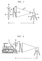
- Fig. 1 shows a system in which the present invention has advantageous applicability
- Fig. 2 shows another system in which the present invention has advantageous applicability
- Fig. 3 illustrates a synchronization problem and shows two asynchronous time scales
- Fig. 4 illustrates extrapolation of an elevation angle
- Fig. 5 shows a high level block diagram of a device configured in accordance with one embodiment of the invention.
- Fig. 6 is a flow diagram showing the steps performed during operation of the apparatus shown in Fig. 5.
- the system comprises a rotary laser device 27 for projecting a fan-shaped beam by rotary irradiation and a photodetection sensor device 28 for receiving the fan-shaped beam.
- a tripod 29 is installed so that the tripod is approximately aligned with a known point X, and the rotary laser device 27 is mounted on the tripod 29.
- the rotary laser device 27 comprises a main unit 31 and a rotator 32 rotatably mounted on the main unit 31.
- a laser beam 33 is projected by rotary irradiation from the rotator 32.
- the photodetection sensor device 28 is supported by a predetermined supporting means.
- Fig. 1 shows how the device is operated in field operation.
- the photodetection sensor device 28 is installed on a rod 34, which can be manually carried by an operator.
- On an upper end of the rod 34 there is provided a GPS position measuring device 30. By using the GPS position measuring device 30, an absolute position on the ground can be measured based on a signal from a navigation satellite.
- the laser beam 33 comprises a plurality of fan-shaped laser beams 33a and 33b in a vertical direction and a fan-shaped beam 33c tilted diagonally with respect to the fan-shaped beams 33a and 33b at an angle of ⁇ , forming an N-shaped configuration. Also, the laser beams 33a and 33b are projected in a direction of ⁇ ⁇ with a spreading angle ⁇ respectively.
- FIG. 2 Another system in which the present invention has advantageous applicability is shown in Fig. 2.
- the photodetector device 28 is fixed on a working tool of a construction machine (e.g., on a blade 18 of a bulldozer 17).
- a mounting pole 19 is erected on the blade 18, and the photodetection sensor device 28 is mounted on the mounting pole 19, and a GPS position measuring device 30 is installed at an upper end of the mounting pole 19.
- the bulldozer 17 comprises an excavation operation control unit (not shown) such as a computer to control the operation of the blade 19.
- the photodetection sensor device comprises a photodetection unit for receiving the fan-shaped beams and an arithmetic unit for calculating an elevation angle relative to the rotary laser device based on photodetection signals produced when the photodetection unit receives the light beam.
- the elevation angle produced by the photodetection sensor device may be used in conjunction with the GPS position measuring device to increase the accuracy of the position determination task.
- Fig. 3 shows two asynchronous time scales.
- the solid line signal pulses e.g., signal pulse 102
- the broken line signal pulses e.g., signal pulse 104
- the delay is represented in Fig. 3.
- Fig. 4 line 130 represents the actual elevation angle over time of the mobile unit.
- the varying elevation angle may be the result, for example, of the photodetection device being mounted on construction equipment as shown in Fig. 2.
- Broken vertical lines 402a, 402b, 402c and 402d represent the event pulses (104 in Fig. 3) and are the times that the rotating laser beam strikes the photodetector device.
- accurate elevation angles are computed as follows.
- Time 137 represents a GPS epoch moment, controlled by the local clock of the GPS unit, at which time a GPS position calculation is made. As discussed above, it is desirable to augment the GPS position calculation with the elevation angle information. However, at time 137 the most recent elevation angle information 404c was calculated at time 402c. There is a latency as represented by 120. One method of reducing the latency error is to extrapolate the elevation angle calculations to time 137. Such extrapolation requires a mathematical model of the change in elevation angle.
- a polynomial model is generally used for such extrapolation, as illustrated in Fig. 4 as the parabolic extrapolation 140 over the three points 404a, 404b and 404c.
- this algebraic model is not effective and extrapolation error 150 results. This extrapolation error decreases the effectiveness of the integration of the elevation angle data with GPS position data.
- the present invention reduces the extrapolation error by better synchronizing the generation of the GPS position data with the generation of the elevation angle data.
- Fig. 5 shows a high level block diagram of a device 500 configured in accordance with one embodiment of the invention. It is noted that this block diagram is meant to describe the high level functioning and configuration of device 500.
- some of the blocks represent hardware components while other blocks represent some function or operation.
- the functions and operations may be performed by hardware circuits, software instructions executing on a processor, firmware, or some combination of hardware and software. Given the description herein, those skilled in the art would be able to implement the described functionality using well known and various combinations of hardware and software. As such, implementation details of the functions described herein will not be described in detail as such implementation details would be readily known to one skilled in the art.
- the device 500 comprises a satellite antenna 502 which receives satellite signals and provides the satellite signals to a satellite signal processor 508.
- the satellite signal processor 508 processes the satellite signals, calculates GPS position, and controls the local clock 518 as will be described in further detail below.
- the local clock 518 generates the epoch signal and local time which is used for processing the GPS signals in the satellite signal processor.
- the device 500 also comprises a laser detector 504 which detects the rotating laser beam and provides signals representative of the received laser beam to a laser signal processor 520.
- the laser signal processor 520 processes the signal received from laser detector 504 in order to extrapolate an elevation angle as described above.
- the laser detector 504 outputs an event signal 506 which, as described above, is the timing signal indicating the time at which the laser beam was received by the laser detector 504.
- This event signal 506 is provided to a time difference module 514.
- Time difference module 514 also receives the epoch signal 516 from local clock 518.
- the time difference module 514 calculates a clock correction based on the received signals and the clock correction is applied to the local clock 518 in order to better synchronize the GPS epoch signal and the laser detector event signal. This improved synchronization results in a reduced extrapolation error.
- Fig. 6 Further details of the operation of the apparatus shown in Fig. 5 will now be described with reference to the flow diagram of Fig. 6.
- steps shown in Fig. 6 and described herein may be implemented using various hardware and software configurations. For example, in one embodiment, the steps may be performed by one or more processors executing computer program instructions.
- step 602 the local time t is determined.
- the local clock 518 contains a local quartz oscillator that is used to keep track of local time based on counting.
- step 604 the time of the event signal, or event time (T event ) is determined with reference to local time t.
- step 606 the offset (T offset ) between GPS time and local time t is calculated.
- GPS time is the time scale of the satellite system which is controlled by an atomic clock onboard the satellite.
- the offset between GPS time and local time is calculated as a result of processing the satellite signals in the satellite signal processor 508. This calculation is based on processing the pseudoranges from at least four satellites and is a well known GNSS technique.
- step 608 it is determined whether the T offset calculated in step 606 is greater than zero. If it is, then in step 610 one half of an epoch period (T epoch ) is added to T offset . If the T offset calculated in step 606 is not greater than zero, then one half of an epoch period (T epoch ) is subtracted from T offset in step 612. This technique of adding or subtracting one half of an epoch interval proves a zero mean value of time offset between GPS time and local clock time. After step 610 or 612, the local clock correction is calculated in step 614 by the following equation:
- step 614 The correction T corr calculated in step 614 is applied to the local clock 518 to adjust the local time in step 616.
- the steps shown in Fig. 6 are repeated each time an event signal 506 is received from the laser detector 504 indicating that the laser detector 504 has received the laser beam signal. While other various embodiments are possible, in one embodiment of the invention, step 606 is performed by the satellite signal processor 508 and the remaining steps are performed by the time difference module 514 and the local clock 518.
- the method described in conjunction with Fig. 6 results in the local clock 518 being adjusted so that the event time and the epoch time are more closely synchronized.
- the elevation angle data 522 provided from the laser detector 504 to the laser signal processor 520 is the elevation angle data of a time moment very close to the time moment that the satellite signal processor 508 calculates the GPS position. This results in a smaller extrapolation error in the calculation of the elevation angle by laser signal processor 520.
- the GPS position 524 and the elevation angle 526 are provided to the integration module 512. Since the GPS position and the elevation angle were substantially synchronously determined, the resulting position determination which uses both pieces of data is more accurate than in prior art solutions.
- the non-satellite signal being used to augment the GPS data is from a rotating N-shaped laser
- the non-satellite signal may be any type of signal which may be used in combination with the GPS data to augment the position determination.
Abstract
Description

Claims (10)
- A method for synchronizing a satellite positioning device having a local clock with a non-satellite signal comprising the steps of:a) receiving said non-satellite signal at a first time;b) calculating a clock correction based at least in part on said first time;c) applying said clock correction to the local clock of the satellite signal processor.
- The method of claim 1 wherein said steps a) - c) are repeated each time said non-satellite signal is received.
- The method of claim 1 wherein said step of calculating a clock correction further comprises the steps of:determining a local time t based on said local clock;determining a time T event as said first time with reference to local time t;determining a time offset T offset as between satellite time and local time t;adding one half of an epoch period to T offset if T offset is greater than 0;subtracting one half of an epoch period from T offset if T offset is not greater than 0; calculating a clock correction T corr asand

applying said clock correction T corr to said local clock. - The method of claim 1 wherein said non-satellite signal is a laser beam generated by a rotating laser transmitter.
- The method of claim 4 wherein the period of said rotating laser transmitter is substantially equal to said epoch period.
- The method of claim 4 wherein said laser beam has an N shape.
- A satellite positioning device comprising:a local clock;a satellite signal processor for processing satellite signals and generating position information, whereby timing epochs of said processing are based on said local clock;a non-satellite signal processor for processing received non-satellite signals; anda time difference module for generating a clock correction signal based at least in part on the time of receipt of said non-satellite signals.
- The satellite positioning device of claim 7 wherein said non-satellite signal processor is a laser signal processor.
- The satellite positioning device of claim 8 further comprising a laser detector connected to said laser signal processor.
- The satellite positioning device of claim 7 wherein said time difference module is configured to generate a clock correction signal by performing the steps of:determining a local time t based on said local clock;determining a time T event as the time of receipt of a non-satellite signal with reference to local time t;determining a time offset T offset as between satellite time and local time t;adding one half of an epoch period to T offset if T offset is greater than 0;subtracting one half of an epoch period from T offset if T offset is not greater than 0;calculating a clock correction T corr as

Applications Claiming Priority (2)
| Application Number | Priority Date | Filing Date | Title |
|---|---|---|---|
| US10/810,293 US7123186B2 (en) | 2004-03-26 | 2004-03-26 | Controlling solution latency in a global navigation satellite receiver |
| US810293 | 2004-03-26 |
Publications (2)
| Publication Number | Publication Date |
|---|---|
| EP1580571A1 true EP1580571A1 (en) | 2005-09-28 |
| EP1580571B1 EP1580571B1 (en) | 2010-10-06 |
Family
ID=34862108
Family Applications (1)
| Application Number | Title | Priority Date | Filing Date |
|---|---|---|---|
| EP05002791A Active EP1580571B1 (en) | 2004-03-26 | 2005-02-10 | Controlling latency between data from global navigation satellites and data from a rotating laser system |
Country Status (6)
| Country | Link |
|---|---|
| US (1) | US7123186B2 (en) |
| EP (1) | EP1580571B1 (en) |
| JP (2) | JP4574409B2 (en) |
| AT (1) | ATE483991T1 (en) |
| CA (1) | CA2494490C (en) |
| DE (1) | DE602005023924D1 (en) |
Cited By (2)
| Publication number | Priority date | Publication date | Assignee | Title |
|---|---|---|---|---|
| WO2009112935A1 (en) * | 2008-03-13 | 2009-09-17 | Toyota Jidosha Kabushiki Kaisha | Positioning device for moving body |
| US9746329B2 (en) | 2006-11-08 | 2017-08-29 | Caterpillar Trimble Control Technologies Llc | Systems and methods for augmenting an inertial navigation system |
Families Citing this family (9)
| Publication number | Priority date | Publication date | Assignee | Title |
|---|---|---|---|---|
| US7123186B2 (en) * | 2004-03-26 | 2006-10-17 | Topcon Gps, Llc | Controlling solution latency in a global navigation satellite receiver |
| US7710944B1 (en) * | 2006-09-15 | 2010-05-04 | Itt Manufacturing Enterprises, Inc. | Method and apparatus for time-of-day synchronization between network nodes |
| KR101051876B1 (en) | 2007-02-13 | 2011-07-26 | 주식회사 코아로직 | Positioning device and method |
| JP2009036571A (en) * | 2007-07-31 | 2009-02-19 | Toshiba Corp | Position measuring system utilizing visible light communication system, position measuring device, and position measuring method |
| JP2012185111A (en) * | 2011-03-08 | 2012-09-27 | Seiko Epson Corp | Positioning device and positioning method |
| CN105300410B (en) * | 2015-12-01 | 2018-01-12 | 中国矿业大学 | Coal-winning machine inertial navigation position error calibrating installation and method |
| US10816995B2 (en) * | 2018-08-24 | 2020-10-27 | Baidu Usa Llc | GPS based high precision timestamp generation circuit for an autonomous driving vehicle |
| US11852725B2 (en) * | 2019-02-08 | 2023-12-26 | Topcon Positioning Systems, Inc. | System and method for determining an elevation of a laser detector |
| US11649613B2 (en) * | 2020-02-25 | 2023-05-16 | Trimble Inc. | Tracking a position of a working edge on an implement of a construction vehicle |
Citations (3)
| Publication number | Priority date | Publication date | Assignee | Title |
|---|---|---|---|---|
| US6150980A (en) * | 1996-03-08 | 2000-11-21 | Snaptrack, Inc. | Method and apparatus for determining time for GPS receivers |
| US6433739B1 (en) * | 1998-03-17 | 2002-08-13 | Qualcomm, Incorporated | Method and apparatus for synchronizing base stations using remote synchronizing stations |
| US6433866B1 (en) | 1998-05-22 | 2002-08-13 | Trimble Navigation, Ltd | High precision GPS/RTK and laser machine control |
Family Cites Families (9)
| Publication number | Priority date | Publication date | Assignee | Title |
|---|---|---|---|---|
| US732145A (en) * | 1902-11-20 | 1903-06-30 | John Henry Walker | Trolley. |
| US4602375A (en) * | 1982-06-11 | 1986-07-22 | Communications Satellite Corporation | Onboard clock correction by means of drift prediction |
| JPH07239236A (en) * | 1994-02-28 | 1995-09-12 | Hitachi Ltd | Method and apparatus for measurement of quantity of state of moving body and calculation device of attitude angle of moving body |
| US6075987A (en) * | 1998-02-27 | 2000-06-13 | Ericsson Inc. | Stand alone global positioning system (GPS) and method with high sensitivity |
| US6353412B1 (en) * | 1998-03-17 | 2002-03-05 | Qualcomm, Incorporated | Method and apparatus for determining position location using reduced number of GPS satellites and synchronized and unsynchronized base stations |
| JP2001324560A (en) * | 2000-05-16 | 2001-11-22 | Sony Corp | Navigation device and gps receiver |
| AUPR863401A0 (en) * | 2001-11-02 | 2001-11-29 | Qx Corporation Pty Ltd | A method & device for precision time-lock |
| JP2004212058A (en) * | 2002-12-26 | 2004-07-29 | Topcon Corp | Working position measuring apparatus |
| US7123186B2 (en) * | 2004-03-26 | 2006-10-17 | Topcon Gps, Llc | Controlling solution latency in a global navigation satellite receiver |
-
2004
- 2004-03-26 US US10/810,293 patent/US7123186B2/en active Active
-
2005
- 2005-01-26 CA CA2494490A patent/CA2494490C/en not_active Expired - Fee Related
- 2005-02-10 EP EP05002791A patent/EP1580571B1/en active Active
- 2005-02-10 AT AT05002791T patent/ATE483991T1/en not_active IP Right Cessation
- 2005-02-10 DE DE602005023924T patent/DE602005023924D1/en active Active
- 2005-03-25 JP JP2005087879A patent/JP4574409B2/en not_active Expired - Fee Related
-
2010
- 2010-02-18 JP JP2010033275A patent/JP2010160157A/en active Pending
Patent Citations (3)
| Publication number | Priority date | Publication date | Assignee | Title |
|---|---|---|---|---|
| US6150980A (en) * | 1996-03-08 | 2000-11-21 | Snaptrack, Inc. | Method and apparatus for determining time for GPS receivers |
| US6433739B1 (en) * | 1998-03-17 | 2002-08-13 | Qualcomm, Incorporated | Method and apparatus for synchronizing base stations using remote synchronizing stations |
| US6433866B1 (en) | 1998-05-22 | 2002-08-13 | Trimble Navigation, Ltd | High precision GPS/RTK and laser machine control |
Cited By (2)
| Publication number | Priority date | Publication date | Assignee | Title |
|---|---|---|---|---|
| US9746329B2 (en) | 2006-11-08 | 2017-08-29 | Caterpillar Trimble Control Technologies Llc | Systems and methods for augmenting an inertial navigation system |
| WO2009112935A1 (en) * | 2008-03-13 | 2009-09-17 | Toyota Jidosha Kabushiki Kaisha | Positioning device for moving body |
Also Published As
| Publication number | Publication date |
|---|---|
| DE602005023924D1 (en) | 2010-11-18 |
| JP2005283579A (en) | 2005-10-13 |
| US20050212702A1 (en) | 2005-09-29 |
| CA2494490A1 (en) | 2005-09-26 |
| US7123186B2 (en) | 2006-10-17 |
| ATE483991T1 (en) | 2010-10-15 |
| JP2010160157A (en) | 2010-07-22 |
| CA2494490C (en) | 2011-04-19 |
| EP1580571B1 (en) | 2010-10-06 |
| JP4574409B2 (en) | 2010-11-04 |
Similar Documents
| Publication | Publication Date | Title |
|---|---|---|
| CA2494490C (en) | Controlling solution latency in a global navigation satellite receiver | |
| US20090115656A1 (en) | Systems and Methods for Global Differential Positioning | |
| US7193559B2 (en) | Inertial GPS navigation system with modified kalman filter | |
| CA2595378C (en) | Method and apparatus for accurately determining height coordinates in a satellite/laser positioning system | |
| US7671794B2 (en) | Attitude estimation using intentional translation of a global navigation satellite system (GNSS) antenna | |
| US7668629B2 (en) | Ultra-tightly coupled global navigation satellite system space borne receiver system | |
| EP0870174B1 (en) | Improved vehicle navigation system and method using gps velocities | |
| EP0870173B1 (en) | Improved vehicle navigation system and method | |
| EP0870175B1 (en) | A zero motion detection system for improved vehicle navigation system | |
| US9347205B2 (en) | Estimation of the relative attitude and position between a vehicle body and an implement operably coupled to the vehicle body | |
| US6308134B1 (en) | Vehicle navigation system and method using multiple axes accelerometer | |
| EP4303630A2 (en) | Gnss and inertial navigation system utilizing relative yaw as an observable for an ins filter | |
| US6266584B1 (en) | Robust autonomous GPS time reference for space application | |
| EP2790036B1 (en) | Position output device using satellite navigation system | |
| JP6008509B2 (en) | Measuring device and measuring method | |
| JP2019060620A (en) | Movement state determining device, electronic timepiece, movement state determination method and program | |
| JP2009236532A (en) | Method for geolocation, program, and apparatus for geolocation | |
| JP6008510B2 (en) | Measuring device and measuring method | |
| US8547276B2 (en) | Positioning system and method | |
| JP4474558B2 (en) | GPS navigation system for space flight and its operation method | |
| JP2010060421A (en) | Positioning system for moving body and gnss receiving apparatus |
Legal Events
| Date | Code | Title | Description |
|---|---|---|---|
| PUAI | Public reference made under article 153(3) epc to a published international application that has entered the european phase |
Free format text: ORIGINAL CODE: 0009012 |
|
| AK | Designated contracting states |
Kind code of ref document: A1 Designated state(s): AT BE BG CH CY CZ DE DK EE ES FI FR GB GR HU IE IS IT LI LT LU MC NL PL PT RO SE SI SK TR |
|
| AX | Request for extension of the european patent |
Extension state: AL BA HR LV MK YU |
|
| 17P | Request for examination filed |
Effective date: 20060120 |
|
| AKX | Designation fees paid |
Designated state(s): AT BE BG CH CY CZ DE DK EE ES FI FR GB GR HU IE IS IT LI LT LU MC NL PL PT RO SE SI SK TR |
|
| GRAP | Despatch of communication of intention to grant a patent |
Free format text: ORIGINAL CODE: EPIDOSNIGR1 |
|
| GRAS | Grant fee paid |
Free format text: ORIGINAL CODE: EPIDOSNIGR3 |
|
| GRAA | (expected) grant |
Free format text: ORIGINAL CODE: 0009210 |
|
| AK | Designated contracting states |
Kind code of ref document: B1 Designated state(s): AT BE BG CH CY CZ DE DK EE ES FI FR GB GR HU IE IS IT LI LT LU MC NL PL PT RO SE SI SK TR |
|
| REG | Reference to a national code |
Ref country code: GB Ref legal event code: FG4D |
|
| REG | Reference to a national code |
Ref country code: CH Ref legal event code: EP |
|
| REG | Reference to a national code |
Ref country code: IE Ref legal event code: FG4D |
|
| REF | Corresponds to: |
Ref document number: 602005023924 Country of ref document: DE Date of ref document: 20101118 Kind code of ref document: P |
|
| REG | Reference to a national code |
Ref country code: NL Ref legal event code: VDEP Effective date: 20101006 |
|
| PG25 | Lapsed in a contracting state [announced via postgrant information from national office to epo] |
Ref country code: SI Free format text: LAPSE BECAUSE OF FAILURE TO SUBMIT A TRANSLATION OF THE DESCRIPTION OR TO PAY THE FEE WITHIN THE PRESCRIBED TIME-LIMIT Effective date: 20101006 |
|
| LTIE | Lt: invalidation of european patent or patent extension |
Effective date: 20101006 |
|
| PG25 | Lapsed in a contracting state [announced via postgrant information from national office to epo] |
Ref country code: LT Free format text: LAPSE BECAUSE OF FAILURE TO SUBMIT A TRANSLATION OF THE DESCRIPTION OR TO PAY THE FEE WITHIN THE PRESCRIBED TIME-LIMIT Effective date: 20101006 |
|
| PG25 | Lapsed in a contracting state [announced via postgrant information from national office to epo] |
Ref country code: FI Free format text: LAPSE BECAUSE OF FAILURE TO SUBMIT A TRANSLATION OF THE DESCRIPTION OR TO PAY THE FEE WITHIN THE PRESCRIBED TIME-LIMIT Effective date: 20101006 Ref country code: NL Free format text: LAPSE BECAUSE OF FAILURE TO SUBMIT A TRANSLATION OF THE DESCRIPTION OR TO PAY THE FEE WITHIN THE PRESCRIBED TIME-LIMIT Effective date: 20101006 Ref country code: BG Free format text: LAPSE BECAUSE OF FAILURE TO SUBMIT A TRANSLATION OF THE DESCRIPTION OR TO PAY THE FEE WITHIN THE PRESCRIBED TIME-LIMIT Effective date: 20110106 Ref country code: IS Free format text: LAPSE BECAUSE OF FAILURE TO SUBMIT A TRANSLATION OF THE DESCRIPTION OR TO PAY THE FEE WITHIN THE PRESCRIBED TIME-LIMIT Effective date: 20110206 Ref country code: SE Free format text: LAPSE BECAUSE OF FAILURE TO SUBMIT A TRANSLATION OF THE DESCRIPTION OR TO PAY THE FEE WITHIN THE PRESCRIBED TIME-LIMIT Effective date: 20101006 Ref country code: PT Free format text: LAPSE BECAUSE OF FAILURE TO SUBMIT A TRANSLATION OF THE DESCRIPTION OR TO PAY THE FEE WITHIN THE PRESCRIBED TIME-LIMIT Effective date: 20110207 Ref country code: AT Free format text: LAPSE BECAUSE OF FAILURE TO SUBMIT A TRANSLATION OF THE DESCRIPTION OR TO PAY THE FEE WITHIN THE PRESCRIBED TIME-LIMIT Effective date: 20101006 |
|
| PG25 | Lapsed in a contracting state [announced via postgrant information from national office to epo] |
Ref country code: GR Free format text: LAPSE BECAUSE OF FAILURE TO SUBMIT A TRANSLATION OF THE DESCRIPTION OR TO PAY THE FEE WITHIN THE PRESCRIBED TIME-LIMIT Effective date: 20110107 |
|
| PG25 | Lapsed in a contracting state [announced via postgrant information from national office to epo] |
Ref country code: CZ Free format text: LAPSE BECAUSE OF FAILURE TO SUBMIT A TRANSLATION OF THE DESCRIPTION OR TO PAY THE FEE WITHIN THE PRESCRIBED TIME-LIMIT Effective date: 20101006 Ref country code: ES Free format text: LAPSE BECAUSE OF FAILURE TO SUBMIT A TRANSLATION OF THE DESCRIPTION OR TO PAY THE FEE WITHIN THE PRESCRIBED TIME-LIMIT Effective date: 20110117 Ref country code: EE Free format text: LAPSE BECAUSE OF FAILURE TO SUBMIT A TRANSLATION OF THE DESCRIPTION OR TO PAY THE FEE WITHIN THE PRESCRIBED TIME-LIMIT Effective date: 20101006 |
|
| PLBE | No opposition filed within time limit |
Free format text: ORIGINAL CODE: 0009261 |
|
| STAA | Information on the status of an ep patent application or granted ep patent |
Free format text: STATUS: NO OPPOSITION FILED WITHIN TIME LIMIT |
|
| PG25 | Lapsed in a contracting state [announced via postgrant information from national office to epo] |
Ref country code: DK Free format text: LAPSE BECAUSE OF FAILURE TO SUBMIT A TRANSLATION OF THE DESCRIPTION OR TO PAY THE FEE WITHIN THE PRESCRIBED TIME-LIMIT Effective date: 20101006 Ref country code: PL Free format text: LAPSE BECAUSE OF FAILURE TO SUBMIT A TRANSLATION OF THE DESCRIPTION OR TO PAY THE FEE WITHIN THE PRESCRIBED TIME-LIMIT Effective date: 20101006 Ref country code: RO Free format text: LAPSE BECAUSE OF FAILURE TO SUBMIT A TRANSLATION OF THE DESCRIPTION OR TO PAY THE FEE WITHIN THE PRESCRIBED TIME-LIMIT Effective date: 20101006 Ref country code: SK Free format text: LAPSE BECAUSE OF FAILURE TO SUBMIT A TRANSLATION OF THE DESCRIPTION OR TO PAY THE FEE WITHIN THE PRESCRIBED TIME-LIMIT Effective date: 20101006 |
|
| 26N | No opposition filed |
Effective date: 20110707 |
|
| PG25 | Lapsed in a contracting state [announced via postgrant information from national office to epo] |
Ref country code: MC Free format text: LAPSE BECAUSE OF NON-PAYMENT OF DUE FEES Effective date: 20110228 |
|
| REG | Reference to a national code |
Ref country code: CH Ref legal event code: PL |
|
| PG25 | Lapsed in a contracting state [announced via postgrant information from national office to epo] |
Ref country code: CH Free format text: LAPSE BECAUSE OF NON-PAYMENT OF DUE FEES Effective date: 20110228 Ref country code: LI Free format text: LAPSE BECAUSE OF NON-PAYMENT OF DUE FEES Effective date: 20110228 |
|
| REG | Reference to a national code |
Ref country code: DE Ref legal event code: R097 Ref document number: 602005023924 Country of ref document: DE Effective date: 20110707 |
|
| REG | Reference to a national code |
Ref country code: IE Ref legal event code: MM4A |
|
| PG25 | Lapsed in a contracting state [announced via postgrant information from national office to epo] |
Ref country code: IE Free format text: LAPSE BECAUSE OF NON-PAYMENT OF DUE FEES Effective date: 20110210 |
|
| PG25 | Lapsed in a contracting state [announced via postgrant information from national office to epo] |
Ref country code: CY Free format text: LAPSE BECAUSE OF FAILURE TO SUBMIT A TRANSLATION OF THE DESCRIPTION OR TO PAY THE FEE WITHIN THE PRESCRIBED TIME-LIMIT Effective date: 20101006 Ref country code: LU Free format text: LAPSE BECAUSE OF NON-PAYMENT OF DUE FEES Effective date: 20110210 |
|
| PG25 | Lapsed in a contracting state [announced via postgrant information from national office to epo] |
Ref country code: TR Free format text: LAPSE BECAUSE OF FAILURE TO SUBMIT A TRANSLATION OF THE DESCRIPTION OR TO PAY THE FEE WITHIN THE PRESCRIBED TIME-LIMIT Effective date: 20101006 |
|
| PG25 | Lapsed in a contracting state [announced via postgrant information from national office to epo] |
Ref country code: HU Free format text: LAPSE BECAUSE OF FAILURE TO SUBMIT A TRANSLATION OF THE DESCRIPTION OR TO PAY THE FEE WITHIN THE PRESCRIBED TIME-LIMIT Effective date: 20101006 |
|
| REG | Reference to a national code |
Ref country code: FR Ref legal event code: PLFP Year of fee payment: 11 |
|
| PGFP | Annual fee paid to national office [announced via postgrant information from national office to epo] |
Ref country code: IT Payment date: 20150205 Year of fee payment: 11 |
|
| PGFP | Annual fee paid to national office [announced via postgrant information from national office to epo] |
Ref country code: FR Payment date: 20150129 Year of fee payment: 11 |
|
| PGFP | Annual fee paid to national office [announced via postgrant information from national office to epo] |
Ref country code: BE Payment date: 20150130 Year of fee payment: 11 |
|
| PG25 | Lapsed in a contracting state [announced via postgrant information from national office to epo] |
Ref country code: BE Free format text: LAPSE BECAUSE OF NON-PAYMENT OF DUE FEES Effective date: 20160229 |
|
| REG | Reference to a national code |
Ref country code: FR Ref legal event code: ST Effective date: 20161028 |
|
| PG25 | Lapsed in a contracting state [announced via postgrant information from national office to epo] |
Ref country code: IT Free format text: LAPSE BECAUSE OF NON-PAYMENT OF DUE FEES Effective date: 20160210 |
|
| PG25 | Lapsed in a contracting state [announced via postgrant information from national office to epo] |
Ref country code: FR Free format text: LAPSE BECAUSE OF NON-PAYMENT OF DUE FEES Effective date: 20160229 |
|
| PGFP | Annual fee paid to national office [announced via postgrant information from national office to epo] |
Ref country code: GB Payment date: 20230227 Year of fee payment: 19 Ref country code: DE Payment date: 20230223 Year of fee payment: 19 |