EP1585000A1 - Image capturing apparatus for process automation devices - Google Patents
Image capturing apparatus for process automation devices Download PDFInfo
- Publication number
- EP1585000A1 EP1585000A1 EP04008517A EP04008517A EP1585000A1 EP 1585000 A1 EP1585000 A1 EP 1585000A1 EP 04008517 A EP04008517 A EP 04008517A EP 04008517 A EP04008517 A EP 04008517A EP 1585000 A1 EP1585000 A1 EP 1585000A1
- Authority
- EP
- European Patent Office
- Prior art keywords
- image
- capture device
- actuator
- image capture
- data
- Prior art date
- Legal status (The legal status is an assumption and is not a legal conclusion. Google has not performed a legal analysis and makes no representation as to the accuracy of the status listed.)
- Granted
Links
Images

Classifications
-
- G—PHYSICS
- G06—COMPUTING; CALCULATING OR COUNTING
- G06T—IMAGE DATA PROCESSING OR GENERATION, IN GENERAL
- G06T1/00—General purpose image data processing
- G06T1/0007—Image acquisition
-
- H—ELECTRICITY
- H04—ELECTRIC COMMUNICATION TECHNIQUE
- H04L—TRANSMISSION OF DIGITAL INFORMATION, e.g. TELEGRAPHIC COMMUNICATION
- H04L12/00—Data switching networks
- H04L12/28—Data switching networks characterised by path configuration, e.g. LAN [Local Area Networks] or WAN [Wide Area Networks]
- H04L12/40—Bus networks
- H04L2012/4026—Bus for use in automation systems
Definitions
- the invention relates to an image capture device for detection of image data one by at least one actuator along a moving path moving object, wherein the image capture device designed as a camera.
- the invention further relates to a control module for such Image capture device.
- Such an image capture device is for example known from DE 100 33 366 A1.
- the image capture device in the form of a camera allows the detection of optical Data of an object generated by a handling device is moved with two actuators.
- the image capture device transmits data to a control computer containing the handling device controls with the two actuators.
- the known handling system can be made of modular, build standardized components. However, it is disadvantageous that several, to be matched components necessary.
- control means For controlling the at least one actuator.
- the image acquisition device fulfills two tasks: Collection and expediently analysis of image data and Furthermore, the control of one or more actuators.
- the actor or the actuators expediently form a component a handling device provided by the image capture device is controlled.
- the Image acquisition device in the form of a camera in addition a controller for one or more actuators, that is for an actuator arrangement.
- In the video area usually 50 or 60 frames per second.
- the image capture device detected in a preferred embodiment as a high-speed camera, preferably 200 to 400 frames per second, including embodiments with greater performance, for example, 1,000 images per second, or lower efficiency with more than about 50-60 frames per second, for example 100 pictures per second, are possible without further ado.
- the image capture device has accordingly via a powerful image processing processor, which additionally fulfills the control tasks.
- the Image acquisition device works expediently in one correlating to the speed of movement of the at least one actuator Speed, especially in real time.
- the Control means are opposite to the image data processing means advantageously prioritized.
- the image capture device advantageously allows a highly dynamic evaluation of image data and generated on this way expediently image analysis data.
- the image analysis data sets the image capture device for the control tasks that is, it controls the actuator (s) based on the image analysis data. It is understood that the invention also includes an image capture device having a provides lower operating speed.
- the control means are advantageously for detection from by the at least one actuator and / or by at least a sensor reported feedback configured in for example, a relative position of an actuator member the actuator or the like is reported.
- the control means are advantageously via a programming interface programmable, with at least one movement of the actuator is programmable.
- the control means work expediently as a flow control.
- For the Programming is a standardized programming language preferred, for example, according to IEC-11631.
- control means as a programmable logic Control (PLC) is appropriate. It is also possible that the Control means a programmable logic controller, so to speak emulate. The control means then work according to one Programmable logic controller, that is, for example the programming of the control means takes the form of a Programmable logic controller.
- PLC programmable logic Control
- the control means communicate with the at least one actuator directly or indirectly.
- the direct communication can be, for example via output interfaces, e.g. a bus interface or the like.
- indirect communication is for example a separate input-output module available as a subordinate unit is executed.
- the image capture device and the input-output module are conveniently via a bus connection connected with each other.
- image capture device contains web interface means to output data in a page description language.
- the image capture device forms expediently a kind of web server, so they by means of an Internet browser is operable.
- the image capture device may Output visualization data and / or programming commands received for programming the control means.
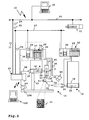
- a handling system 10 shown in Figure 1 includes handling means 11, 12, through an image capture device 13 are controlled.
- a central control computer 30 controls the image capture device 13 and an actuator 31 via a central control bus 29, for example a field bus, an Ethernet bus or the like.
- a central control bus 29 can also be further actuator arrangements, subordinate programmable logic Controllers or the like connected be.
- the image capture device 13 forms a local controller for the handling devices 11, 12, in which a valve battery 14, actuators 16, 17 and a valve battery 15 a Actuator 18 drives.
- a valve battery 14, actuators 16, 17 and a valve battery 15 a Actuator 18 drives To the valve batteries 14, 15 can also connected, not shown in the figure actuators be.
- the valve batteries 14, 15 operate in the present case on a fluidic, in particular pneumatic basis, that is, they act on the actuators 16, 17, 18 with compressed air, to actuate their actuator members 22, 23, 24.
- the image capture device 13 controls the actuators 16 to 18 indirectly via the valve batteries 14, 15, in particular via Control modules 25, 26 of the valve batteries 14, 15, with which the image capture device 13 via a field bus 27, for example an ASi bus (actuator sensor interface) or a CAN bus (Controller Area Network), is connected.
- the Control modules 25, 26 form local input-output modules for Actuation of the actuators 16, 17 and 18.
- the control modules 25, 26 control valve modules, for example valve modules 19, 20, 21, to which the actuators 16, 17, 18 by means of fluid lines, e.g. Compressed air lines are connected.
- the image capture device 13 also for the direct control of actuators, in particular electrical Actors, can be designed, and then no Intermediate input-output modules are necessary.
- the image capture device 13 controls a from her separate illumination device 104, e.g. a lamp, directly on and switches these brightness-dependent on and out.
- bus connection between the image capture device 13 and the control modules 25, 26 can also direct Connections in the form of lines 28 between the image capture device 13 and the control modules 25, 26 are provided be. It is understood that even wireless connections, For example, via a wireless LAN, are possible.
- the image capture device 13 is configured as a camera and has an objective 40. Furthermore, the Image capture device 13 from a separate camera 89 via a line 91 image data 90.
- the handling devices 11, 12 are for handling of Objects provided, for example, workpieces, tools or similar.
- an object 32 that is in the Drawing of the handling device 11 is moved, shown.
- the handling device 11 transfers the object 32 of the handling device 12 and moves the object, for example along a movement path shown schematically 36th
- the handling devices 11, 12 are multi-axis handling devices, which is shown schematically in the drawing are.
- the actuator 16 horizontally oriented arranged on a stand 33.
- the actuator member 22 moves, for example, a piston rod which is arranged on a pneumatic piston, from a housing of the actuator 16 out or in this.
- the Actuator 22 is actuated in the X direction.
- the actuator 16 and the actuator 17 is a pneumatic Linear actuator.
- the actuator 17 is oriented vertically, the means, when actuated by the valve module 20, the actuator member leads 23, for example, a piston rod, a movement in the Y direction, that is, the piston rod 23 moves up or down.
- Aktorglieds 23 is a fluidic holding device in the form of a nipple 34, the corresponding actuation by the valve module 35th the object 32 sucks or repels.
- the valve module 35 is with a vacuum generating device, not shown connected.
- a gripper 37 for example, electric or pneumatic is operable, the object takes 32nd
- the gripper 37 is arranged at the front, free end of the Aktorglieds.
- Actuator 18 is also horizontally oriented, that is Actuator member 24, e.g. a piston rod, is movable in the X direction or drivable.
- pneumatic linear actuators shown. It is understood that other drive variants, For example, electric drives, rotary actuators or the like are possible.
- the image capture device 13 is overlaid by a Control device in the form of the control computer 30 controllable.
- the control computer 30 sends, for example, a control command 39 to the image capture device 13 for movement of the object 32 along the path of movement 36.
- the Execution of the control command 39 acknowledges the image capture device 13, for example, with an acknowledgment 62.
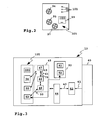
- the image capture device 13 is schematic in FIG shown.
- An image converter 42 converts incident through the object 40 Light 41 in image data 43, here digital image data. It it is understood that analogue image data 43 are also possible.
- a processor 44 performs different based on the image data 43 Control tasks, which will be explained later become.
- the processor 44 is for analyzing image data and additionally designed to carry out control tasks.
- the processor executes program code from program modules 45 for example, an analysis module 46 for analyzing the Image data 43, 90, a control module 47 for controlling the handling devices 11, 12 and a visualization module 48 for the visualization of image data, of control functions or the like.
- the control module 47 controls the actuators 16, 17, 18 on the basis of Control command 39 of the control computer 30 and based on parameter data 52, a movement of the actuators 16, 17, 18 represent. Further, the control module 47 evaluates image analysis data 49, the analysis module 46 based on the image data 43, 90 generated.
- the image analysis data 49 signal for example, a correct or an incorrect movement of the object 32 by the handling devices 11, 12.
- the parameter data 52 includes, for example, an ideal one geometric path 55 of the object 32 along the Trajectory 36, which is shown in Figure 4. Furthermore, can in the parameter data 52 also a time-dependent, ideal Route 65 according to Figure 5 and / or a time-dependent ideal Velocity profile 84 parameterized according to FIG. 6 be.
- the control module 47 forms control means for controlling the actuators 16 to 18.
- the analysis module 46 forms detection means for the detection and in the present case for the analysis of image data, for example the image data 43 and / or 90.
- the control module 47 and the analysis module 46 act in an advantageous manner below described way together:
- the analysis module 46 analyzes the image data 43, 90 in geometric Respect, but also in dynamic terms.
- the analysis module 46 analyzes the image data 43 several positions of the movement path 36, in particular along at least one subsection of the movement path 36.
- the handling devices 11, 12 move the Object 32 along the ideal geometric course 55 according to Figure 4.
- the movements overlap the actuators 16 to 18, so that is a typical geometric History 56 sets.
- the course 56 is located inside a geometric tolerance band 57, which by a bounded lower and upper limit 58, 59 is.
- the analysis module 46 sends a warning information 61st to the control module 47.
- the control module 47 may then, for example send a warning message to the control computer 30 and / or the actuators 16, 17 and / or 18 to a corrected, the ideal geometric path 55 approximate movement of the object 32 to drive.
- the geometric tolerance band 57 is a warning tolerance band, so to speak.
- the analysis module 46 is configured to the object 32 as well optionally further, not shown in the figure Identify objects, including, for example, an identification code or an identification identifier 51 on the object evaluates.
- the identifier 51 is For example, a data matrix code, a bar code or similar.
- the analysis module 46 may e.g. based on Image data 43 also evaluate object features of the object 32, to determine the identity of the object 32.
- the analysis module 46 can display further properties of the object 32 determine, for example, its location, its dimensions, its Distances from one or more obstacles as well as its Surface quality.
- the aforementioned analysis data for example a part number, an identification code, Survey data, distance data, alignment data / location data and / or surface data, the image capture device may 13 to the superimposed control device in Transmit shape of the control computer 30.
- the analysis module 46 is also capable of one or several dynamic properties of the object 32 at least a position along the trajectory 36 to analyze and trigger a follow-up action, for example warning information in the nature of the warning information 36 to send.
- a dynamic property is, for example, by represents the path progression 65 or the velocity course 84.
- the analysis module 46 is parameterized, for example, that the time-dependent path course of the object 32 along the trajectory 36 move within a tolerance band 67 must be that through a lower and an upper limit 68, 69 is limited.
- a typical path-time curve 66 is in Figure 4 shown by a solid line. It is but possible that the path-time history is wrong, which is indicated by a dotted line 70. The dotted Line 70 leaves the tolerance band 67 upwards. Accordingly, the analysis module 46 sends a Warning information in the manner of the warning information 61 to the Control module 47, whereupon this the actuators 16 to 18 to a correct handling of the object 32 is driving.
- tolerance bands for example an alarm tolerance band 79 and an emergency tolerance band 86 for the speed of the object 32 along the trajectory 36 are defined.
- the analysis module 46 sends an alarm message 77 to the control computer 30.
- Such an overrun is for example, by the error-speed course 85 given that reaches an alarm speed 75.
- the analysis module 46 sends an emergency message 78 the control module 47.
- Control module 47 for example, the actuators 16, 17, 18 directly at.
- the control module 47 then sends, for example Hold command 74 to the control modules 25, 26 of the valve batteries 14, 15 about this to a stop of the actuators 16 to 18 to instruct.
- a visualization / parameterization device 102 in the form a personal computer is used to visualize Visualization data 50, which generates the visualization module 48. Furthermore, the device 102 allows a parameterization the parameter data 52 at a parameterization interface 53.
- the image capture device 13 and the visualization / parameterization device 102 communicate via one wireless connection, such as a Wi-Fi connection.
- the parameterization interface 53 contains, for example, a Radio controller.
- the parameterization interface 53 is at Embodiment at the same time a visualization interface to output the visualization data 50, for example an image sequence 93 containing a movement of the object 32 along the trajectory 36 shows.
- the image sequence 93 and the parameter data 52 are in one Memory 92 stored, via a connection, not shown is connected to the processor 44.
- In the store 92 are also not shown in the program modules 45 and may be used by the processor 44 to execute their program code are read from the memory 92.
- the parameterization interface 53 is a kind of web server designed, that is, it provides the visualization data 50, for example, as multimedia data ready, conveniently embedded in code of a page description language, e.g. HTML (Hypertext Markup Language).
- a page description language e.g. HTML (Hypertext Markup Language).
- the memory 92 is for long-term storage of image sequences designed, for example, the image sequence 93. Usually be reflected in the memory 92 image sequences again deleted, for example, the oldest image data be replaced by current image data. In dependence of a trigger condition, such as an alarm condition or an emergency condition (eg, when the emergency tolerance band 86 exits is), the image capture device 13 stores the Image sequence 92 in a long-term memory area of the memory 92. From this long-term storage area, the respective Image sequence for later analysis, for example, with help the visualization device 102, are read.
- a trigger condition such as an alarm condition or an emergency condition (eg, when the emergency tolerance band 86 exits is)
- the image capture device 13 stores the Image sequence 92 in a long-term memory area of the memory 92. From this long-term storage area, the respective Image sequence for later analysis, for example, with help the visualization device 102, are read.
- These Function is particularly in the commissioning of the handling devices 11, 12 advantageous, but also in the ongoing operation,
- FIGS 2 and 3 are interface means 105 of the image capture device 13 partially shown.
- a connection 94 for example, a plug connection
- a plug-in connector is powered by a bus controller 96 serves and serves to connect the field bus 27.
- a Digital-to-analog converter arrangement or analog-to-digital converter arrangement 98 is an input-output connector 97 assigned and allows, for example, the switching and / or dimming the illumination device 104 and / or the Connection of external sensors, for example a position sensor 87 on the actuator 16.
- the position sensor 87 sends a digital or analog position signal 88 to the image capture device 13, the position, for example, the End position, the actuator member 22 signals.
- the control module 47 can the position signal 88 for controlling the actuators 16 to 18, in particular to control the actuator 16, evaluate.
- An Ethernet controller 100 operates an Ethernet port 99, for example in the form of an RJ-45 connector, for connection to the control bus 29. It is understood that others Buses as Ethernet as well as various wired and wireless connection types are possible.
- Display means 101 for example LEDs signal operating states the image capture device 13, for example Normal operation, failure, emergency stop.
- the ports 94, 95, 97 are suitably in a high Degree of protection realized, for example, IP 65/67.
- the image capture device according to the invention can be implemented in software and / or hardware.
- the image capture device 13 may also include a gateway between the field bus 27 and the superimposed control bus 29 form and for example messages of the control modules 25, 26 on the Transform bus 27 into messages on the bus 29 and / or in reverse direction control commands of the control computer 30 the bus 29 as control commands on the bus 27 output.
Abstract
Description
Die Erfindung betrifft eine Bilderfassungsvorrichtung zur Erfassung von Bilddaten eines durch mindestens einen Aktor entlang einer Bewegungsbahn bewegten Objekts, wobei die Bilderfassungsvorrichtung als eine Kamera ausgestaltet ist. Die Erfindung betrifft ferner ein Steuermodul für eine derartige Bilderfassungsvorrichtung.The invention relates to an image capture device for detection of image data one by at least one actuator along a moving path moving object, wherein the image capture device designed as a camera. The invention further relates to a control module for such Image capture device.
Eine derartige Bilderfassungsvorrichtung ist beispielsweise aus der DE 100 33 366 A1 bekannt. Die Bilderfassungsvorrichtung in Gestalt einer Kamera ermöglicht die Erfassung optischer Daten eines Objekts, das durch eine Handhabungsvorrichtung mit zwei Aktoren bewegt wird. Die Bilderfassungsvorrichtung übermittelt Daten an einen Steuerrechner, der die Handhabungsvorrichtung mit den beiden Aktoren steuert.Such an image capture device is for example known from DE 100 33 366 A1. The image capture device in the form of a camera allows the detection of optical Data of an object generated by a handling device is moved with two actuators. The image capture device transmits data to a control computer containing the handling device controls with the two actuators.
Das bekannte Handhabungssystem lässt sich aus modularen, standardisierten Komponenten aufbauen. Allerdings ist es nachteilig, dass mehrere, aufeinander abzustimmende Komponenten notwendig sind.The known handling system can be made of modular, build standardized components. However, it is disadvantageous that several, to be matched components necessary.
Es ist daher die Aufgabe der vorliegenden Erfindung, Vorrichtungen bereit zu stellen, die bei kompakter Bauweise Steuerungs- und Bildverarbeitungsaufgaben erfüllen. It is therefore the object of the present invention, devices to provide, in a compact design, control and image processing tasks.
Bei einer Bilderfassungsvorrichtung der eingangs genannten Art ist zur Lösung der Aufgabe vorgesehen, dass sie Steuermittel zur Steuerung des mindestens einen Aktors aufweist.In an image capture device of the aforementioned Art is provided to solve the problem that they control means For controlling the at least one actuator.
Die erfindungsgemäße Bilderfassungsvorrichtung bzw. ein entsprechend ausgestaltetes Steuermodul erfüllen zwei Aufgaben: Erfassung und zweckmäßigerweise Analyse von Bilddaten und ferner die Steuerung eines oder mehrerer Aktoren. Der Aktor bzw. die Aktoren bilden zweckmäßigerweise einen Bestandteil einer Handhabungsvorrichtung, die durch die Bilderfassungsvorrichtung gesteuert wird. Erfindungsgemäß verkörpert die Bilderfassungsvorrichtung in Gestalt einer Kamera zusätzlich eine Steuerung für einen oder mehrere Aktoren, das heißt für eine Aktoranordnung. Im Videobereich werden üblicherweise 50 oder 60 Bilder pro Sekunde erfasst. Die erfindungsgemäße Bilderfassungsvorrichtung erfasst in einer bevorzugten Ausführungsform als eine Hochgeschwindigkeitskamera vorzugsweise 200 bis 400 Bilder pro Sekunde, wobei auch Ausführungsformen mit größerer Leistungsfähigkeit, beispielsweise 1.000 Bilder pro Sekunde, oder kleinerer Leistungsfähigkeit mit mehr als etwa 50-60 Einzelbildern pro Sekunde, beispielsweise 100 Bilder pro Sekunde, ohne weiteres möglich sind.The image acquisition device according to the invention or a corresponding The configured control module fulfills two tasks: Collection and expediently analysis of image data and Furthermore, the control of one or more actuators. The actor or the actuators expediently form a component a handling device provided by the image capture device is controlled. According to embodies the Image acquisition device in the form of a camera in addition a controller for one or more actuators, that is for an actuator arrangement. In the video area usually 50 or 60 frames per second. The image capture device according to the invention detected in a preferred embodiment as a high-speed camera, preferably 200 to 400 frames per second, including embodiments with greater performance, for example, 1,000 images per second, or lower efficiency with more than about 50-60 frames per second, for example 100 pictures per second, are possible without further ado.
Die erfindungsgemäße Bilderfassungsvorrichtung verfügt dementsprechend über einen leistungsfähigen Bildverarbeitungsprozessor, der zusätzlich die Steuerungsaufgaben erfüllt. Die Bilderfassungsvorrichtung arbeitet zweckmäßigerweise in einer zur Bewegungsgeschwindigkeit des mindestens einen Aktors korrelierenden Geschwindigkeit, insbesondere in Echtzeit. Die Steuermittel sind gegenüber den Bilddaten verarbeitenden Mitteln vorteilhafterweise priorisiert.The image capture device according to the invention has accordingly via a powerful image processing processor, which additionally fulfills the control tasks. The Image acquisition device works expediently in one correlating to the speed of movement of the at least one actuator Speed, especially in real time. The Control means are opposite to the image data processing means advantageously prioritized.
Die Bilderfassungsvorrichtung ermöglicht vorteilhafterweise eine hochdynamische Auswertung von Bilddaten und erzeugt auf diesem Weg zweckmäßigerweise Bildanalysedaten. Die Bildanalysedaten setzt die Bilderfassungsvorrichtung für die Steuerungsaufgaben ein, das heißt sie steuert den oder die Aktoren anhand der Bildanalysedaten. Es versteht sich, dass die Erfindung auch eine Bilderfassungsvorrichtung umfasst, die eine geringere Arbeitsgeschwindigkeit bereitstellt.The image capture device advantageously allows a highly dynamic evaluation of image data and generated on this way expediently image analysis data. The image analysis data sets the image capture device for the control tasks that is, it controls the actuator (s) based on the image analysis data. It is understood that the invention Also includes an image capture device having a provides lower operating speed.
Weitere vorteilhafte Ausgestaltungen der Erfindung ergeben sich aus den abhängigen Ansprüchen sowie aus der Beschreibung.Further advantageous embodiments of the invention result from the dependent claims as well as from the description.
Die Steuerungsmittel sind vorteilhafterweise zur Erfassung von durch den mindestens einen Aktor und/oder durch mindestens einen Sensor gemeldete Rückmeldungen ausgestaltet, in denen beispielsweise eine Relativposition eines Aktorglieds des Aktors oder dergleichen gemeldet wird.The control means are advantageously for detection from by the at least one actuator and / or by at least a sensor reported feedback configured in for example, a relative position of an actuator member the actuator or the like is reported.
Die Steuermittel sind vorteilhafterweise über eine Programmier-Schnittstelle programmierbar, wobei mindestens ein Bewegungsablauf des Aktors programmierbar ist. Die Steuermittel arbeiten zweckmäßigerweise als eine Ablauf-Steuerung. Für die Programmierung ist eine standardisierte Programmiersprache bevorzugt, beispielsweise gemäß IEC-11631.The control means are advantageously via a programming interface programmable, with at least one movement of the actuator is programmable. The control means work expediently as a flow control. For the Programming is a standardized programming language preferred, for example, according to IEC-11631.
Ein Aufbau der Steuermittel als eine speicherprogrammierbare Steuerung (SPS) ist zweckmäßig. Es ist auch möglich, dass die Steuermittel eine speicherprogrammierbare Steuerung sozusagen emulieren. Die Steuermittel arbeiten dann entsprechend einer speicherprogrammierbaren Steuerung, das heißt beispielsweise die Programmierung der Steuermittel erfolgt in der Art einer speicherprogrammierbaren Steuerung.A structure of the control means as a programmable logic Control (PLC) is appropriate. It is also possible that the Control means a programmable logic controller, so to speak emulate. The control means then work according to one Programmable logic controller, that is, for example the programming of the control means takes the form of a Programmable logic controller.
Die Steuermittel kommunizieren mit dem mindestens einen Aktor direkt oder indirekt. Die direkte Kommunikation kann beispielsweise über Ausgabeschnittstellen, z.B. eine Busschnittstelle oder dergleichen, erfolgen. Bei der indirekten Kommunikation ist beispielsweise ein separates Eingabe-Ausgabemodul vorhanden, das als eine unterlagerte Baueinheit ausgeführt ist. Die Bilderfassungsvorrichtung und das Eingabe-Ausgabemodul sind zweckmäßigerweise über eine Bus-Verbindung miteinander verbunden.The control means communicate with the at least one actuator directly or indirectly. The direct communication can be, for example via output interfaces, e.g. a bus interface or the like. In indirect communication is for example a separate input-output module available as a subordinate unit is executed. The image capture device and the input-output module are conveniently via a bus connection connected with each other.
Weitere Schnittstellenmittel sind bei der Bilderfassungsvorrichtung zweckmäßig. Beispielsweise enthält sie Web-Schnittstellenmittel zur Ausgabe von Daten in einer Seitenbeschreibungssprache. Die Bilderfassungsvorrichtung bildet zweckmäßigerweise eine Art Web-Server, so dass sie mittels eines Internet-Browsers bedienbar ist. An der Web-Schnittstelle kann die Bilderfassungsvorrichtung beispielsweise Visualisierungsdaten ausgeben und/oder Programmierbefehle zur Programmierung der Steuermittel empfangen.Other interface means are in the image capture device appropriate. For example, it contains web interface means to output data in a page description language. The image capture device forms expediently a kind of web server, so they by means of an Internet browser is operable. At the web interface For example, the image capture device may Output visualization data and / or programming commands received for programming the control means.
Nachfolgend wird die Erfindung anhand eines Ausführungsbeispiels unter Bezugnahme auf die Zeichnung näher erläutert. Es zeigen:
- Figur 1
- ein Handhabungssystem, bei dem eine erfindungsgemäße Bilderfassungsvorrichtung zwei Handhabungsvorrichtungen steuert,
- Figur 2
- eine Rückseite der Bilderfassungsvorrichtung gemäß Figur 1,
- Figur 3
- eine schematische Ansicht der Bilderfassungsvorrichtung gemäß Figur 1,
- Figur 4
- schematische geometrische Bewegungsbahnverläufe eines durch die Handhabungsvorrichtungen gemäß Figur 1 bewegten Objekts sowie ein zugeordnetes geometrisches Toleranzband,
- Figur 5
- schematische Weg-Zeit-Verläufe von Bewegungsbahnen, die ein durch die Handhabungsvorrichtungen gemäß Figur 1 bewegtes Objekt durchläuft, sowie ein zugeordnetes geometrisches Toleranzband und
- Figur 6
- schematische zeitabhängige Geschwindigkeitsverläufe eines durch die Handhabungsvorrichtungen gemäß Figur 1 bewegten Objektes sowie zwei zugeordnete Toleranzbänder.
- FIG. 1
- a handling system in which an image capture device according to the invention controls two handling devices,
- FIG. 2
- a rear side of the image acquisition device according to FIG. 1,
- FIG. 3
- 1 is a schematic view of the image acquisition device according to FIG. 1,
- FIG. 4
- schematic geometric trajectory courses of an object moved by the handling devices according to FIG. 1 and an associated geometric tolerance band,
- FIG. 5
- schematic path-time courses of trajectories, which passes through an object moved by the handling devices according to Figure 1, and an associated geometric tolerance band and
- FIG. 6
- schematic time-dependent speed profiles of an object moved by the handling devices according to FIG. 1 and two associated tolerance bands.
Ein in Figur 1 gezeigtes Handhabungssystem 10 enthält Handhabungsvorrichtung
11, 12, die durch eine Bilderfassungsvorrichtung
13 gesteuert werden. Ein zentraler Steuer-Rechner 30
steuert die Bilderfassungsvorrichtung 13 sowie einen Aktor 31
über einen zentralen Steuerbus 29, beispielsweise einen Feldbus,
einen Ethernet-Bus oder dergleichen. An den Steuerbus 29
können auch weitere Aktoranordnungen, unterlagerte speicherprogrammierbare
Steuerungen oder dergleichen angeschlossen
sein.A
Die Bilderfassungsvorrichtung 13 bildet eine lokale Steuerung
für die Handhabungsvorrichtungen 11, 12, bei denen eine Ventilbatterie
14, Aktoren 16, 17 und eine Ventilbatterie 15 einen
Aktor 18 ansteuert. An die Ventilbatterien 14, 15 können
auch weitere, in der Figur nicht dargestellte Aktoren angeschlossen
sein. Die Ventilbatterien 14, 15 arbeiten vorliegend
auf fluidtechnischer, insbesondere pneumatischer Basis,
das heißt sie beaufschlagen die Aktoren 16, 17, 18 mit Druckluft,
um deren Aktorglieder 22, 23, 24 zu betätigen.The
Die Bilderfassungsvorrichtung 13 steuert die Aktoren 16 bis
18 indirekt über die Ventilbatterien 14, 15, insbesondere über
Steuermodule 25, 26 der Ventilbatterien 14, 15, mit denen
die Bilderfassungsvorrichtung 13 über einen Feldbus 27, beispielsweise
einen ASi-Bus (actuator sensor interface) oder
einen CAN-Bus (Controller Area Network), verbunden ist. Die
Steuermodule 25, 26 bilden lokale Eingabe-Ausgabemodule zur
Ansteuerung der Aktoren 16, 17 und 18. Die Steuermodule 25,
26 steuern Ventilmodule, beispielsweise Ventilmodule 19, 20,
21 an, an die die Aktoren 16, 17, 18 mittels Fluid-Leitungen,
z.B. Druckluftleitungen, angeschlossen sind.The
Es versteht sich, dass die Bilderfassungsvorrichtung 13 auch
zur direkten Ansteuerung von Aktoren, insbesondere von elektrischen
Aktoren, ausgestaltet sein kann, wobei dann keine
zwischengeschalteten Eingabe-Ausgabe-Module notwendig sind.
Beispielsweise steuert die Bilderfassungsvorrichtung 13 eine
von ihr separate Beleuchtungseinrichtung 104, z.B. eine Lampe,
direkt an und schaltet diese helligkeitsabhängig ein und
aus.It is understood that the
Anstelle der Bus-Verbindung zwischen der Bilderfassungsvorrichtung
13 und den Steuermodulen 25, 26 können auch direkte
Verbindungen in Gestalt von Leitungen 28 zwischen der Bilderfassungsvorrichtung
13 und den Steuermodulen 25, 26 vorgesehen
sein. Es versteht sich, dass auch drahtlose Verbindungen,
beispielsweise über ein Wireless-LAN, möglich sind.Instead of the bus connection between the
Die Bilderfassungsvorrichtung 13 ist als eine Kamera ausgestaltet
und weist ein Objektiv 40 auf. Ferner empfängt die
Bilderfassungsvorrichtung 13 von einer separaten Kamera 89
über eine Leitung 91 Bilddaten 90.The
Die Handhabungsvorrichtungen 11, 12 sind zur Handhabung von
Objekten vorgesehen, beispielsweise Werkstücken, Werkzeugen
oder dergleichen. Beispielhaft ist ein Objekt 32, das in der
Zeichnung von der Handhabungsvorrichtung 11 bewegt wird, dargestellt.
Die Handhabungsvorrichtung 11 übergibt das Objekt
32 der Handhabungsvorrichtung 12 und bewegt das Objekt beispielsweise
entlang einer schematisch dargestellten Bewegungsbahn
36.The
Die Handhabungsvorrichtungen 11, 12 sind Mehrachs-Handhabungsvorrichtungen,
die in der Zeichnung schematisch dargestellt
sind. Bei der Handhabungsvorrichtung 11 ist der Aktor
16 horizontal orientiert an einem Ständer 33 angeordnet. Bei
entsprechender Druckluftbeaufschlagung durch das Ventilmodul
19 bewegt sich das Aktorglied 22, beispielsweise eine Kolbenstange
die an einem pneumatischen Kolben angeordnet ist, aus
einem Gehäuse des Aktors 16 heraus bzw. in dieses hinein. Das
Aktorglied 22 ist in X-Richtung betätigbar.The
Am freien Ende des Aktorglieds 22 ist der Aktor 17 angeordnet.
Wie der Aktor 16 ist auch der Aktor 17 ein pneumatischer
Linear-Antrieb. Der Aktor 17 ist vertikal orientiert, das
heißt, bei Betätigung durch das Ventilmodul 20 führt das Aktorglied
23, beispielsweise eine Kolbenstange, eine Bewegung
in Y-Richtung aus, das heißt die Kolbenstange 23 bewegt sich
nach oben oder unten.At the free end of
Am unteren, freien Ende des Aktorglieds 23 befindet sich eine
fluidtechnische Halteeinrichtung in Gestalt eines Saugers 34,
der bei entsprechender Betätigung durch das Ventilmodul 35
das Objekt 32 ansaugt bzw. abstößt. Das Ventilmodul 35 ist
mit einer nicht dargestellten Vakuumerzeugungseinrichtung
verbunden. Durch entsprechen synchronisierte Betätigung der
Aktoren 16, 17 bzw. des Saugers 32 kann die Handhabungsvorrichtung
11 das Objekt 32 positionieren, beispielsweise der
Handhabungsvorrichtung 12 übergeben.At the lower, free end of
Ein Greifer 37, der beispielsweise elektrisch oder pneumatisch
betätigbar ist, ergreift das Objekt 32. Der Greifer 37
ist am vorderen, freien Ende des Aktorglieds angeordnet. Der
Aktor 18 ist ebenfalls horizontal orientiert, das heißt das
Aktorglied 24, z.B. eine Kolbenstange, ist in X-Richtung beweglich
bzw. antreibbar.A
Beim Ausführungsbeispiel sind pneumatische Linear-Antriebe dargestellt. Es versteht sich, dass auch andere Antriebsvarianten, beispielsweise elektrische Antriebe, Drehantriebe oder dergleichen möglich sind. In the embodiment, pneumatic linear actuators shown. It is understood that other drive variants, For example, electric drives, rotary actuators or the like are possible.
Die Bilderfassungsvorrichtung 13 ist durch eine überlagerte
Steuerungsvorrichtung in Gestalt des Steuerrechners 30 steuerbar.
Der Steuerrechner 30 sendet beispielsweise einen Steuerbefehl
39, um die Bilderfassungsvorrichtung 13 zur Bewegung
des Objekts 32 entlang der Bewegungsbahn 36 anzuweisen. Die
Ausführung des Steuerbefehls 39 quittiert die Bilderfassungsvorrichtung
13 beispielsweise mit einer Quittiermeldung 62.The
Die Bilderfassungsvorrichtung 13 ist in Figur 3 schematisch
dargestellt.The
Ein Bildwandler 42 wandelt durch das Objekt 40 einfallendes
Licht 41 in Bilddaten 43, vorliegend digitale Bilddaten. Es
versteht sich, dass auch analoge Bilddaten 43 möglich sind.
Ein Prozessor 44 führt anhand der Bilddaten 43 verschiedene
Steuerungsaufgaben durch, die später noch näher erläutert
werden. Der Prozessor 44 ist zur Analyse von Bilddaten und
zusätzlich zur Durchführung von Steuerungsaufgaben ausgestaltet.
Der Prozessor führt Programmcode von Programmmodulen 45
aus, die beispielsweise ein Analysemodul 46 zur Analyse der
Bilddaten 43, 90, ein Steuermodul 47 zur Steuerung der Handhabungsvorrichtungen
11, 12 und ein Visualisierungsmodul 48
zur Visualisierung von Bilddaten, von Steuerungsfunktionen
oder dergleichen enthalten.An
Das Steuermodul 47 steuert die Aktoren 16, 17, 18 anhand des
Steuerbefehls 39 des Steuerrechners 30 sowie anhand von Parameterdaten
52, die einen Bewegungsablauf der Aktoren 16, 17,
18 repräsentieren. Ferner wertet das Steuermodul 47 Bildanalysedaten
49 aus, die das Analysemodul 46 anhand der Bilddaten
43, 90 erzeugt. Die Bildanalysedaten 49 signalisieren
beispielsweise eine korrekte oder eine nicht korrekte Bewegung
des Objekts 32 durch die Handhabungsvorrichtungen 11,
12. Die Parameterdaten 52 enthalten beispielsweise einen idealen
geometrischen Wegverlauf 55 des Objekts 32 entlang der
Bewegungsbahn 36, der in Figur 4 dargestellt ist. Ferner kann
in den Parameterdaten 52 auch ein zeitabhängiger, idealer
Wegverlauf 65 gemäß Figur 5 und/oder ein zeitabhängiger idealer
Geschwindigkeitsverlauf 84 gemäß Figur 6 parametriert
sein.The
Das Steuermodul 47 bildet Steuermittel zur Steuerung der Aktoren
16 bis 18. Das Analysemodul 46 bildet Erfassungsmittel
zur Erfassung und vorliegend zur Analyse von Bilddaten, beispielsweise
der Bilddaten 43 und/oder 90. Das Steuermodul 47
und das Analysemodul 46 wirken in einer vorteilhaften, nachfolgend
beschriebenen Weise zusammen:The
Das Analysemodul 46 analysiert die Bilddaten 43, 90 in geometrischer
Hinsicht, zusätzlich aber auch in dynamischer Hinsicht.
Das Analysemodul 46 analysiert die Bilddaten 43 an
mehreren Positionen der Bewegungsbahn 36, insbesondere entlang
mindestens eines Teilabschnitts der Bewegungsbahn 36.
Idealerweise bewegen die Handhabungsvorrichtungen 11, 12 das
Objekt 32 entlang dem idealen geometrischen Verlauf 55 gemäß
Figur 4. In der Praxis jedoch überlagern sich die Bewegungen
der Aktoren 16 bis 18, so dass sich ein typischer geometrischer
Verlauf 56 einstellt. Der Verlauf 56 befindet sich innerhalb
eines geometrischen Toleranzbandes 57, das durch einen
unteren und einen oberen Grenzverlauf 58, 59 begrenzt
ist. Wenn die Aktoren 16 bis 18 das Objekt 32 so bewegen,
dass beispielsweise ein geometrischer Fehler-Verlauf 60
durchlaufen wird, der sich außerhalb des Toleranzbandes 57
befindet, sendet das Analysemodul 46 eine Warninformation 61
an das Steuermodul 47. Das Steuermodul 47 kann dann beispielsweise
eine Warnmeldung an den Steuerrechner 30 senden
und/oder die Aktoren 16, 17 und/oder 18 zu einer korrigierten,
dem idealen geometrischen Wegverlauf 55 angenäherten Bewegung
des Objekts 32 ansteuern. Das geometrische Toleranzband
57 ist sozusagen ein Warn-Toleranzband.The
Das Analysemodul 46 ist dazu ausgestaltet, das Objekt 32 sowie
gegebenenfalls weitere, in der Figur nicht dargestellte
Objekte zu identifizieren, wozu es beispielsweise einen Identifizierungscode
bzw. eine Identifizierungskennung 51 am Objekt
auswertet. Bei der Identifizierungskennung 51 handelt es
sich beispielsweise um einen Datamatrix-Code, einen Bar-Code
oder dergleichen. Das Analysemodul 46 kann z.B. anhand der
Bilddaten 43 auch Objektmerkmale des Objektes 32 auswerten,
um die Identität des Objektes 32 zu ermitteln.The
Das Analysemodul 46 kann weitere Eigenschaften des Objekts 32
ermitteln, beispielsweise dessen Lage, dessen Maße, dessen
Abstände von einem oder mehreren Hindernissen sowie dessen
Oberflächenqualität. Die vorgenannten Analysedaten, die beispielsweise
eine Teilenummer, einen Identifizierungscode,
Vermessungsdaten, Abstandsdaten, Ausrichtungsdaten/Lagedaten
und/oder Oberflächendaten enthalten, kann die Bilderfassungsvorrichtung
13 an die überlagerte Steuerungseinrichtung in
Gestalt des Steuerrechners 30 übermitteln.The
Das Analysemodul 46 ist jedoch auch in der Lage eine oder
mehrere dynamische Eigenschaften des Objekts 32 an mindestens
einer Position entlang der Bewegungsbahn 36 zu analysieren
und eine Folgereaktion auszulösen, beispielsweise eine Warninformation
in der Art der Warninformation 36 zu versenden.
Eine solche dynamische Eigenschaft ist beispielsweise durch
den Weg-Verlauf 65 oder den Geschwindigkeitsverlauf 84 repräsentiert.However, the
Bei dem Analysemodul 46 ist beispielsweise parametriert, dass
der zeitabhängige Weg-Verlauf des Objekts 32 entlang der Bewegungsbahn
36 sich innerhalb eines Toleranzbandes 67 bewegen
muss, dass durch einen unteren und einen oberen Grenzverlauf
68, 69 begrenzt ist. Ein typischer Weg-Zeit-Verlauf 66 ist in
Figur 4 mit einer durchgezogenen Linie dargestellt. Es ist
aber möglich, dass der Weg-Zeit-Verlauf fehlerhaft verläuft,
was durch eine punktierte Linie 70 angedeutet ist. Die punktierte
Linie 70 verlässt das Toleranzband 67 nach oben. Dementsprechend
sendet das Analysemodul 46 beispielsweise eine
Warninformation in der Art der Warninformation 61 an das
Steuermodul 47, worauf dieses die Aktoren 16 bis 18 zu einer
korrigierten Handhabung des Objekts 32 ansteuert.In the
Es ist aber auch möglich, dass mehrere Toleranzbänder, beispielsweise
ein Alarm-Toleranzband 79 und ein Not-Toleranzband
86 für die Geschwindigkeit des Objekts 32 entlang
der Bewegungsbahn 36 definiert sind. Beim Überschreiten
des Alarm-Geschwindigkeitstoleranzbandes 79, das durch einen
unteren und einen oberen Grenzverlauf 80, 81 begrenzt ist,
sendet das Analysemodul 46 beispielsweise eine Alarm-Meldung
77 an den Steuer-Rechner 30. Ein solche Überschreitung ist
beispielsweise durch den Fehler-Geschwindigkeitsverlauf 85
gegeben, der eine Alarm-Geschwindigkeit 75 erreicht.But it is also possible that several tolerance bands, for example
an
Wenn das Objekt 32 entlang der Bewegungsbahn 36 noch schneller
bewegt wird oder unvorgesehen langsam bewegt wird, verlässt
sein Geschwindigkeitsverlauf auch das Not-Toleranzband
86 und erreicht beispielsweise die Not-Geschwindigkeit 76. In
diesem Fall sendet das Analysemodul 46 eine Not-Meldung 78 an
das Steuermodul 47. Bei Eingang der Not-Meldung 78 hält das
Steuermodul 47 beispielsweise die Aktoren 16, 17, 18 unmittelbar
an. Das Steuermodul 47 sendet dann beispielsweise einen
Haltebefehl 74 an die Steuermodule 25, 26 der Ventilbatterien
14, 15 um diese zu einem Anhalten der Aktoren 16 bis
18 zu instruieren.If the
Eine Visualisierungs-/Parametrierungsvorrichtung 102 in Gestalt
eines Personal-Computers dient zur Visualisierung von
Visualisierungsdaten 50, die das Visualisierungsmodul 48 erzeugt.
Ferner ermöglicht die Vorrichtung 102 eine Parametrierung
der Parameterdaten 52 an einer Parametrierschnittstelle
53. Die Bilderfassungsvorrichtung 13 und die Visualisierungs-/Parametriervorrichtung
102 kommunizieren über eine
drahtlose Verbindung, beispielsweise eine WLAN-Verbindung.
Die Parametrierschnittstelle 53 enthält beispielsweise einen
Funkcontroller. Die Parametrier-Schnittstelle 53 ist beim
Ausführungsbeispiel zugleich eine Visualisierungsschnittstelle
zur Ausgabe der Visualisierungsdaten 50, die beispielsweise
eine Bildsequenz 93 enthalten, die eine Bewegung des Objekts
32 entlang der Bewegungsbahn 36 zeigt.A visualization /
Die Bildsequenz 93 sowie die Parameterdaten 52 sind in einem
Speicher 92 abgelegt, der über eine nicht dargestellte Verbindung
mit dem Prozessor 44 verbunden ist. In dem Speicher
92 sind in nicht dargestellter Weise auch die Programmmodule
45 abgelegt und können vom Prozessor 44 zur Ausführung von
deren Programmcode aus dem Speicher 92 ausgelesen werden.The
Die Parametrier-Schnittstelle 53 ist als eine Art Web-Server
ausgestaltet, das heißt sie stellt die Visualisierungsdaten
50 beispielsweise als Multimedia-Daten bereit, zweckmäßigerweise
eingebettet in Code einer Seitenbeschreibungssprache,
z.B. HTML (Hypertext Markup Language).The
Der Speicher 92 ist zur Langzeitspeicherung von Bildsequenzen
ausgestaltet, beispielsweise der Bildsequenz 93. Üblicherweise
werden im Speicher 92 gespeicherte Bildsequenzen wieder
gelöscht, wobei beispielsweise die jeweils ältesten Bilddaten
durch aktuelle Bilddaten ersetzt werden. In Abhängigkeit von
einer Auslösebedingung, beispielsweise einem Alarm-Zustand
oder einem Notzustand (wenn z.B. das Not-Toleranzband 86 verlassen
wird) speichert die Bilderfassungsvorrichtung 13 die
Bildsequenz 92 in einem Langzeit-Speicherbereich des Speicher
92. Aus diesem Langzeit-Speicherbereich kann die jeweilige
Bildsequenz für eine spätere Analyse beispielsweise mit Hilfe
der Visualisierungsvorrichtung 102, ausgelesen werden. Diese
Funktion ist insbesondere bei der Inbetriebnahme der Handhabungsvorrichtungen
11, 12 vorteilhaft, wobei aber auch im
laufenden Betrieb eine Speicherung von Bildsequenzen sinnvoll
ist. An dieser Stelle sei festgehalten, dass die Bilderfassungsvorrichtung
13 für schnelle Bewegungsvorgänge geeignet
ist, das heißt sie kann sozusagen in Zeitlupe Bildsequenzen
erfassen und zu späteren Analyse wieder ausgeben.The
In den Figuren 2 und 3 sind Schnittstellenmittel 105 der Bilderfassungsvorrichtung
13 teilweise dargestellt. An einem Anschluss
94, beispielsweise einem Steckanschluss, ist die Einspeisung
von Strom in die Bilderfassungsvorrichtung 13 möglich.
Ein weiterer Anschluss 95, der zweckmäßigerweise ebenfalls
ein Steckanschluss ist, wird von einem Bus-Controller
96 bedient und dient zum Anschluss des Feldbusses 27. Eine
Digital-Analog-Wandleranordnung oder Analog-Digital-Wandleranordnung
98 ist einem Ein-Ausgabesteckanschluss 97
zugeordnet und ermöglicht beispielsweise das Einschalten
und/oder Dimmen der Beleuchtungseinrichtung 104 und/oder den
Anschluss externer Sensorik, beispielsweise eines Positionssensors
87 am Aktor 16. Der Positionssensor 87 sendet ein digitales
oder analoges Positionssignal 88 an die Bilderfassungsvorrichtung
13, das die Position, beispielsweise die
Endlage, des Aktorglieds 22 signalisiert. Das Steuermodul 47
kann das Positionssignal 88 zur Ansteuerung der Aktoren 16
bis 18, insbesondere zur Ansteuerung des Aktors 16, auswerten.In Figures 2 and 3 are interface means 105 of the
Ein Ethernet-Controller 100 bedient einen Ethernet-Anschluss
99, beispielsweise in Gestalt eines RJ-45-Steckers, zum Anschluss
an den Steuerbus 29. Es versteht sich, dass auch andere
Busse als Ethernet sowie verschiedene drahtgebundene und
drahtlose Verbindungsarten möglich sind.An
Anzeigemittel 101, beispielsweise LEDs signalisieren Betriebszustände
der Bilderfassungsvorrichtung 13, beispielsweise
Normalbetrieb, Störungsfall, Notaus. Display means 101, for example LEDs signal operating states
the
Die Anschlüsse 94, 95, 97 sind zweckmäßigerweise in einer hohen
Schutzart beispielsweise IP 65/67 realisiert.The
Die erfindungsgemäße Bilderfassungsvorrichtung kann in Software und/oder Hardware realisiert sein.The image capture device according to the invention can be implemented in software and / or hardware.
Die Bilderfassungsvorrichtung 13 kann auch ein Gateway zwischen
dem Feldbus 27 und dem überlagerten Steuerbus 29 bilden
und beispielsweise Meldungen der Steuermodule 25, 26 auf dem
Bus 27 in Meldungen auf dem Bus 29 transformieren und/oder in
umgekehrter Richtung Steuerbefehle des Steuer-Rechners 30 auf
dem Bus 29 als Steuerbefehle auf dem Bus 27 ausgeben.The
Claims (23)
Priority Applications (3)
| Application Number | Priority Date | Filing Date | Title |
|---|---|---|---|
| AT04008517T ATE408178T1 (en) | 2004-04-08 | 2004-04-08 | IMAGE CAPTURE DEVICE FOR AUTOMATION DEVICES |
| EP04008517A EP1585000B1 (en) | 2004-04-08 | 2004-04-08 | Image capturing apparatus for process automation devices |
| DE502004008021T DE502004008021D1 (en) | 2004-04-08 | 2004-04-08 | Image capture device for automation devices |
Applications Claiming Priority (1)
| Application Number | Priority Date | Filing Date | Title |
|---|---|---|---|
| EP04008517A EP1585000B1 (en) | 2004-04-08 | 2004-04-08 | Image capturing apparatus for process automation devices |
Publications (2)
| Publication Number | Publication Date |
|---|---|
| EP1585000A1 true EP1585000A1 (en) | 2005-10-12 |
| EP1585000B1 EP1585000B1 (en) | 2008-09-10 |
Family
ID=34896016
Family Applications (1)
| Application Number | Title | Priority Date | Filing Date |
|---|---|---|---|
| EP04008517A Expired - Lifetime EP1585000B1 (en) | 2004-04-08 | 2004-04-08 | Image capturing apparatus for process automation devices |
Country Status (3)
| Country | Link |
|---|---|
| EP (1) | EP1585000B1 (en) |
| AT (1) | ATE408178T1 (en) |
| DE (1) | DE502004008021D1 (en) |
Cited By (2)
| Publication number | Priority date | Publication date | Assignee | Title |
|---|---|---|---|---|
| WO2009007312A1 (en) * | 2007-07-06 | 2009-01-15 | Mettler-Toledo Ag | Checkweight, method and system for back-traceability of such weights |
| DE102013208355A1 (en) * | 2013-05-07 | 2014-11-13 | Krones Ag | Apparatus and method for applying a label sleeve |
Families Citing this family (2)
| Publication number | Priority date | Publication date | Assignee | Title |
|---|---|---|---|---|
| DE102016107527A1 (en) | 2016-04-22 | 2017-10-26 | Beckhoff Automation Gmbh | Real-time environment and programmable logic controller |
| DE102018133058A1 (en) | 2018-12-20 | 2020-06-25 | Beckhoff Automation Gmbh | METHOD FOR CONTROLLING A REAL-TIME AUTOMATION PROCESS |
Citations (4)
| Publication number | Priority date | Publication date | Assignee | Title |
|---|---|---|---|---|
| DE3031507A1 (en) * | 1980-08-21 | 1982-02-25 | Licentia Patent-Verwaltungs-Gmbh, 6000 Frankfurt | Automatic orientation control of industrial manipulator - has video camera monitoring orientation of component for comparison with required position |
| WO1991017021A1 (en) * | 1990-05-09 | 1991-11-14 | Pietro Torielli | Apparatus for the automatic control of a machine, particularly of a shoe making machine |
| US6061603A (en) * | 1997-09-10 | 2000-05-09 | Schneider Automation Inc. | System for remotely accessing an industrial control system over a commercial communications network |
| US20020186302A1 (en) * | 1999-09-03 | 2002-12-12 | Veijo Pulkinnen | Camera control in a process control system |
-
2004
- 2004-04-08 DE DE502004008021T patent/DE502004008021D1/en not_active Expired - Lifetime
- 2004-04-08 AT AT04008517T patent/ATE408178T1/en active
- 2004-04-08 EP EP04008517A patent/EP1585000B1/en not_active Expired - Lifetime
Patent Citations (4)
| Publication number | Priority date | Publication date | Assignee | Title |
|---|---|---|---|---|
| DE3031507A1 (en) * | 1980-08-21 | 1982-02-25 | Licentia Patent-Verwaltungs-Gmbh, 6000 Frankfurt | Automatic orientation control of industrial manipulator - has video camera monitoring orientation of component for comparison with required position |
| WO1991017021A1 (en) * | 1990-05-09 | 1991-11-14 | Pietro Torielli | Apparatus for the automatic control of a machine, particularly of a shoe making machine |
| US6061603A (en) * | 1997-09-10 | 2000-05-09 | Schneider Automation Inc. | System for remotely accessing an industrial control system over a commercial communications network |
| US20020186302A1 (en) * | 1999-09-03 | 2002-12-12 | Veijo Pulkinnen | Camera control in a process control system |
Cited By (4)
| Publication number | Priority date | Publication date | Assignee | Title |
|---|---|---|---|---|
| WO2009007312A1 (en) * | 2007-07-06 | 2009-01-15 | Mettler-Toledo Ag | Checkweight, method and system for back-traceability of such weights |
| EP2165166B1 (en) | 2007-07-06 | 2016-04-06 | Mettler-Toledo GmbH | Control weight, method and system for tracking such weights |
| DE102013208355A1 (en) * | 2013-05-07 | 2014-11-13 | Krones Ag | Apparatus and method for applying a label sleeve |
| EP2801534A3 (en) * | 2013-05-07 | 2014-12-31 | Krones AG | Method and device for applying a label sleeve |
Also Published As
| Publication number | Publication date |
|---|---|
| DE502004008021D1 (en) | 2008-10-23 |
| ATE408178T1 (en) | 2008-09-15 |
| EP1585000B1 (en) | 2008-09-10 |
Similar Documents
| Publication | Publication Date | Title |
|---|---|---|
| EP3140043B1 (en) | Coating system for coating components, in particular for painting motor vehicle body components | |
| DE102008014964B4 (en) | Position control mechanism for double-acting pneumatic cylinders | |
| EP3098034B1 (en) | Selecting an apparatus or an object using a camera | |
| DE102007023585A1 (en) | Device and method for calibrating swivel units, in particular on cutting machines | |
| DE102017213459A1 (en) | robot system | |
| EP2666727B1 (en) | Lifting device for a packing machine | |
| DE112004000504B4 (en) | Actuator with the function of controlling a displacement process | |
| EP1975418B1 (en) | Valve bank | |
| EP1125693A1 (en) | Parallel kinematics system | |
| EP1266147B1 (en) | Fluidic system with a safety function | |
| DE29824557U1 (en) | Intelligent axis | |
| EP0929845A1 (en) | Intelligent control and adjustment device | |
| DE3710688C2 (en) | Robotic tool | |
| EP1585000B1 (en) | Image capturing apparatus for process automation devices | |
| DE102008025845A1 (en) | Drive system, has coupling struts clamped together by spring in transverse direction for retaining components in opposite intervention, and detection unit producing output of electrical warning signal when components reach intervention | |
| EP3098033A1 (en) | Determination of the robot axle angle and selection of a robot with the aid of a camera | |
| EP1584944B1 (en) | Imaging device and process for detecting moving objects | |
| EP1584945B1 (en) | Control module and array of valves associated with an imaging device | |
| DE19639212C2 (en) | Sensor-actuator interface module | |
| DE102019105466B3 (en) | Method for operating a drive system and drive system | |
| EP2644281B1 (en) | Colour changer | |
| DE102017222784A1 (en) | Control device, fluid actuator assembly and method for operating a control device | |
| DE102005050245A1 (en) | Actuator e.g. pneumatic linear drive, controlling module for use in storage unit, has detection unit for determining processing time, which requires actuators during two courses of movements for handling and processing of object | |
| WO2019201488A1 (en) | Multi-member actuated mechanism, preferably robot, particularly preferably articulated-arm robot | |
| DE102020213982B3 (en) | Procedure for commissioning a pneumatic actuator device, commissioning system and pneumatic control module |
Legal Events
| Date | Code | Title | Description |
|---|---|---|---|
| PUAI | Public reference made under article 153(3) epc to a published international application that has entered the european phase |
Free format text: ORIGINAL CODE: 0009012 |
|
| AK | Designated contracting states |
Kind code of ref document: A1 Designated state(s): AT BE BG CH CY CZ DE DK EE ES FI FR GB GR HU IE IT LI LU MC NL PL PT RO SE SI SK TR |
|
| AX | Request for extension of the european patent |
Extension state: AL HR LT LV MK |
|
| 17P | Request for examination filed |
Effective date: 20051025 |
|
| AKX | Designation fees paid |
Designated state(s): AT BE BG CH CY CZ DE DK EE ES FI FR GB GR HU IE IT LI LU MC NL PL PT RO SE SI SK TR |
|
| 17Q | First examination report despatched |
Effective date: 20060922 |
|
| GRAP | Despatch of communication of intention to grant a patent |
Free format text: ORIGINAL CODE: EPIDOSNIGR1 |
|
| RAP1 | Party data changed (applicant data changed or rights of an application transferred) |
Owner name: FESTO AG & CO. KG |
|
| GRAS | Grant fee paid |
Free format text: ORIGINAL CODE: EPIDOSNIGR3 |
|
| GRAA | (expected) grant |
Free format text: ORIGINAL CODE: 0009210 |
|
| AK | Designated contracting states |
Kind code of ref document: B1 Designated state(s): AT BE BG CH CY CZ DE DK EE ES FI FR GB GR HU IE IT LI LU MC NL PL PT RO SE SI SK TR |
|
| REG | Reference to a national code |
Ref country code: GB Ref legal event code: FG4D Free format text: NOT ENGLISH |
|
| REG | Reference to a national code |
Ref country code: CH Ref legal event code: NV Representative=s name: TROESCH SCHEIDEGGER WERNER AG Ref country code: CH Ref legal event code: EP |
|
| REG | Reference to a national code |
Ref country code: IE Ref legal event code: FG4D Free format text: LANGUAGE OF EP DOCUMENT: GERMAN |
|
| REF | Corresponds to: |
Ref document number: 502004008021 Country of ref document: DE Date of ref document: 20081023 Kind code of ref document: P |
|
| REG | Reference to a national code |
Ref country code: SE Ref legal event code: TRGR |
|
| PG25 | Lapsed in a contracting state [announced via postgrant information from national office to epo] |
Ref country code: SI Free format text: LAPSE BECAUSE OF FAILURE TO SUBMIT A TRANSLATION OF THE DESCRIPTION OR TO PAY THE FEE WITHIN THE PRESCRIBED TIME-LIMIT Effective date: 20080910 Ref country code: FI Free format text: LAPSE BECAUSE OF FAILURE TO SUBMIT A TRANSLATION OF THE DESCRIPTION OR TO PAY THE FEE WITHIN THE PRESCRIBED TIME-LIMIT Effective date: 20080910 |
|
| REG | Reference to a national code |
Ref country code: IE Ref legal event code: FD4D |
|
| PG25 | Lapsed in a contracting state [announced via postgrant information from national office to epo] |
Ref country code: IE Free format text: LAPSE BECAUSE OF FAILURE TO SUBMIT A TRANSLATION OF THE DESCRIPTION OR TO PAY THE FEE WITHIN THE PRESCRIBED TIME-LIMIT Effective date: 20080910 Ref country code: BG Free format text: LAPSE BECAUSE OF FAILURE TO SUBMIT A TRANSLATION OF THE DESCRIPTION OR TO PAY THE FEE WITHIN THE PRESCRIBED TIME-LIMIT Effective date: 20081210 Ref country code: ES Free format text: LAPSE BECAUSE OF FAILURE TO SUBMIT A TRANSLATION OF THE DESCRIPTION OR TO PAY THE FEE WITHIN THE PRESCRIBED TIME-LIMIT Effective date: 20081221 |
|
| PG25 | Lapsed in a contracting state [announced via postgrant information from national office to epo] |
Ref country code: PT Free format text: LAPSE BECAUSE OF FAILURE TO SUBMIT A TRANSLATION OF THE DESCRIPTION OR TO PAY THE FEE WITHIN THE PRESCRIBED TIME-LIMIT Effective date: 20090210 Ref country code: CZ Free format text: LAPSE BECAUSE OF FAILURE TO SUBMIT A TRANSLATION OF THE DESCRIPTION OR TO PAY THE FEE WITHIN THE PRESCRIBED TIME-LIMIT Effective date: 20080910 Ref country code: RO Free format text: LAPSE BECAUSE OF FAILURE TO SUBMIT A TRANSLATION OF THE DESCRIPTION OR TO PAY THE FEE WITHIN THE PRESCRIBED TIME-LIMIT Effective date: 20080910 Ref country code: SK Free format text: LAPSE BECAUSE OF FAILURE TO SUBMIT A TRANSLATION OF THE DESCRIPTION OR TO PAY THE FEE WITHIN THE PRESCRIBED TIME-LIMIT Effective date: 20080910 |
|
| PLBE | No opposition filed within time limit |
Free format text: ORIGINAL CODE: 0009261 |
|
| STAA | Information on the status of an ep patent application or granted ep patent |
Free format text: STATUS: NO OPPOSITION FILED WITHIN TIME LIMIT |
|
| PG25 | Lapsed in a contracting state [announced via postgrant information from national office to epo] |
Ref country code: EE Free format text: LAPSE BECAUSE OF FAILURE TO SUBMIT A TRANSLATION OF THE DESCRIPTION OR TO PAY THE FEE WITHIN THE PRESCRIBED TIME-LIMIT Effective date: 20080910 Ref country code: DK Free format text: LAPSE BECAUSE OF FAILURE TO SUBMIT A TRANSLATION OF THE DESCRIPTION OR TO PAY THE FEE WITHIN THE PRESCRIBED TIME-LIMIT Effective date: 20080910 |
|
| 26N | No opposition filed |
Effective date: 20090611 |
|
| BERE | Be: lapsed |
Owner name: FESTO A.G. & CO. KG Effective date: 20090430 |
|
| PG25 | Lapsed in a contracting state [announced via postgrant information from national office to epo] |
Ref country code: MC Free format text: LAPSE BECAUSE OF NON-PAYMENT OF DUE FEES Effective date: 20090430 |
|
| PG25 | Lapsed in a contracting state [announced via postgrant information from national office to epo] |
Ref country code: PL Free format text: LAPSE BECAUSE OF FAILURE TO SUBMIT A TRANSLATION OF THE DESCRIPTION OR TO PAY THE FEE WITHIN THE PRESCRIBED TIME-LIMIT Effective date: 20080910 Ref country code: BE Free format text: LAPSE BECAUSE OF NON-PAYMENT OF DUE FEES Effective date: 20090430 |
|
| PG25 | Lapsed in a contracting state [announced via postgrant information from national office to epo] |
Ref country code: GR Free format text: LAPSE BECAUSE OF FAILURE TO SUBMIT A TRANSLATION OF THE DESCRIPTION OR TO PAY THE FEE WITHIN THE PRESCRIBED TIME-LIMIT Effective date: 20081211 |
|
| PG25 | Lapsed in a contracting state [announced via postgrant information from national office to epo] |
Ref country code: LU Free format text: LAPSE BECAUSE OF NON-PAYMENT OF DUE FEES Effective date: 20090408 |
|
| PG25 | Lapsed in a contracting state [announced via postgrant information from national office to epo] |
Ref country code: HU Free format text: LAPSE BECAUSE OF FAILURE TO SUBMIT A TRANSLATION OF THE DESCRIPTION OR TO PAY THE FEE WITHIN THE PRESCRIBED TIME-LIMIT Effective date: 20090311 |
|
| PG25 | Lapsed in a contracting state [announced via postgrant information from national office to epo] |
Ref country code: TR Free format text: LAPSE BECAUSE OF FAILURE TO SUBMIT A TRANSLATION OF THE DESCRIPTION OR TO PAY THE FEE WITHIN THE PRESCRIBED TIME-LIMIT Effective date: 20080910 |
|
| PG25 | Lapsed in a contracting state [announced via postgrant information from national office to epo] |
Ref country code: CY Free format text: LAPSE BECAUSE OF FAILURE TO SUBMIT A TRANSLATION OF THE DESCRIPTION OR TO PAY THE FEE WITHIN THE PRESCRIBED TIME-LIMIT Effective date: 20080910 |
|
| PGFP | Annual fee paid to national office [announced via postgrant information from national office to epo] |
Ref country code: SE Payment date: 20120416 Year of fee payment: 9 |
|
| PGFP | Annual fee paid to national office [announced via postgrant information from national office to epo] |
Ref country code: NL Payment date: 20130415 Year of fee payment: 10 |
|
| REG | Reference to a national code |
Ref country code: SE Ref legal event code: EUG |
|
| PG25 | Lapsed in a contracting state [announced via postgrant information from national office to epo] |
Ref country code: SE Free format text: LAPSE BECAUSE OF NON-PAYMENT OF DUE FEES Effective date: 20130409 |
|
| PGFP | Annual fee paid to national office [announced via postgrant information from national office to epo] |
Ref country code: CH Payment date: 20140430 Year of fee payment: 11 |
|
| REG | Reference to a national code |
Ref country code: NL Ref legal event code: V1 Effective date: 20141101 |
|
| PG25 | Lapsed in a contracting state [announced via postgrant information from national office to epo] |
Ref country code: NL Free format text: LAPSE BECAUSE OF NON-PAYMENT OF DUE FEES Effective date: 20141101 |
|
| REG | Reference to a national code |
Ref country code: FR Ref legal event code: PLFP Year of fee payment: 12 |
|
| PGFP | Annual fee paid to national office [announced via postgrant information from national office to epo] |
Ref country code: GB Payment date: 20150325 Year of fee payment: 12 |
|
| PGFP | Annual fee paid to national office [announced via postgrant information from national office to epo] |
Ref country code: AT Payment date: 20150407 Year of fee payment: 12 Ref country code: FR Payment date: 20150422 Year of fee payment: 12 Ref country code: IT Payment date: 20150423 Year of fee payment: 12 |
|
| REG | Reference to a national code |
Ref country code: CH Ref legal event code: PL |
|
| PG25 | Lapsed in a contracting state [announced via postgrant information from national office to epo] |
Ref country code: CH Free format text: LAPSE BECAUSE OF NON-PAYMENT OF DUE FEES Effective date: 20150430 Ref country code: LI Free format text: LAPSE BECAUSE OF NON-PAYMENT OF DUE FEES Effective date: 20150430 |
|
| PGFP | Annual fee paid to national office [announced via postgrant information from national office to epo] |
Ref country code: DE Payment date: 20160311 Year of fee payment: 13 |
|
| REG | Reference to a national code |
Ref country code: AT Ref legal event code: MM01 Ref document number: 408178 Country of ref document: AT Kind code of ref document: T Effective date: 20160408 |
|
| GBPC | Gb: european patent ceased through non-payment of renewal fee |
Effective date: 20160408 |
|
| REG | Reference to a national code |
Ref country code: FR Ref legal event code: ST Effective date: 20161230 |
|
| PG25 | Lapsed in a contracting state [announced via postgrant information from national office to epo] |
Ref country code: GB Free format text: LAPSE BECAUSE OF NON-PAYMENT OF DUE FEES Effective date: 20160408 Ref country code: FR Free format text: LAPSE BECAUSE OF NON-PAYMENT OF DUE FEES Effective date: 20160502 |
|
| PG25 | Lapsed in a contracting state [announced via postgrant information from national office to epo] |
Ref country code: AT Free format text: LAPSE BECAUSE OF NON-PAYMENT OF DUE FEES Effective date: 20160408 Ref country code: IT Free format text: LAPSE BECAUSE OF NON-PAYMENT OF DUE FEES Effective date: 20160408 |
|
| REG | Reference to a national code |
Ref country code: DE Ref legal event code: R119 Ref document number: 502004008021 Country of ref document: DE |
|
| PG25 | Lapsed in a contracting state [announced via postgrant information from national office to epo] |
Ref country code: DE Free format text: LAPSE BECAUSE OF NON-PAYMENT OF DUE FEES Effective date: 20171103 |