EP1586879A1 - Determination of a physical parameter by means of an optical device - Google Patents
Determination of a physical parameter by means of an optical device Download PDFInfo
- Publication number
- EP1586879A1 EP1586879A1 EP04101584A EP04101584A EP1586879A1 EP 1586879 A1 EP1586879 A1 EP 1586879A1 EP 04101584 A EP04101584 A EP 04101584A EP 04101584 A EP04101584 A EP 04101584A EP 1586879 A1 EP1586879 A1 EP 1586879A1
- Authority
- EP
- European Patent Office
- Prior art keywords
- optical
- optical property
- center value
- function
- property
- Prior art date
- Legal status (The legal status is an assumption and is not a legal conclusion. Google has not performed a legal analysis and makes no representation as to the accuracy of the status listed.)
- Withdrawn
Links
- 230000003287 optical effect Effects 0.000 title claims abstract description 155
- 238000005259 measurement Methods 0.000 claims abstract description 26
- 238000011156 evaluation Methods 0.000 claims description 24
- 238000000034 method Methods 0.000 claims description 15
- 238000012545 processing Methods 0.000 claims description 6
- 230000000704 physical effect Effects 0.000 claims description 4
- 230000008878 coupling Effects 0.000 claims 2
- 238000010168 coupling process Methods 0.000 claims 2
- 238000005859 coupling reaction Methods 0.000 claims 2
- 239000013307 optical fiber Substances 0.000 description 7
- 238000010586 diagram Methods 0.000 description 5
- 230000000694 effects Effects 0.000 description 5
- 230000007613 environmental effect Effects 0.000 description 5
- 230000001419 dependent effect Effects 0.000 description 4
- 239000000835 fiber Substances 0.000 description 3
- 238000010408 sweeping Methods 0.000 description 3
- 230000001934 delay Effects 0.000 description 2
- 230000010287 polarization Effects 0.000 description 2
- 238000012935 Averaging Methods 0.000 description 1
- 230000005540 biological transmission Effects 0.000 description 1
- 230000003247 decreasing effect Effects 0.000 description 1
- 238000001514 detection method Methods 0.000 description 1
- 230000001747 exhibiting effect Effects 0.000 description 1
- 230000005484 gravity Effects 0.000 description 1
- 239000004576 sand Substances 0.000 description 1
Images

Classifications
-
- G—PHYSICS
- G01—MEASURING; TESTING
- G01L—MEASURING FORCE, STRESS, TORQUE, WORK, MECHANICAL POWER, MECHANICAL EFFICIENCY, OR FLUID PRESSURE
- G01L1/00—Measuring force or stress, in general
- G01L1/24—Measuring force or stress, in general by measuring variations of optical properties of material when it is stressed, e.g. by photoelastic stress analysis using infrared, visible light, ultraviolet
- G01L1/242—Measuring force or stress, in general by measuring variations of optical properties of material when it is stressed, e.g. by photoelastic stress analysis using infrared, visible light, ultraviolet the material being an optical fibre
- G01L1/246—Measuring force or stress, in general by measuring variations of optical properties of material when it is stressed, e.g. by photoelastic stress analysis using infrared, visible light, ultraviolet the material being an optical fibre using integrated gratings, e.g. Bragg gratings
-
- G—PHYSICS
- G01—MEASURING; TESTING
- G01D—MEASURING NOT SPECIALLY ADAPTED FOR A SPECIFIC VARIABLE; ARRANGEMENTS FOR MEASURING TWO OR MORE VARIABLES NOT COVERED IN A SINGLE OTHER SUBCLASS; TARIFF METERING APPARATUS; MEASURING OR TESTING NOT OTHERWISE PROVIDED FOR
- G01D5/00—Mechanical means for transferring the output of a sensing member; Means for converting the output of a sensing member to another variable where the form or nature of the sensing member does not constrain the means for converting; Transducers not specially adapted for a specific variable
- G01D5/26—Mechanical means for transferring the output of a sensing member; Means for converting the output of a sensing member to another variable where the form or nature of the sensing member does not constrain the means for converting; Transducers not specially adapted for a specific variable characterised by optical transfer means, i.e. using infrared, visible, or ultraviolet light
- G01D5/32—Mechanical means for transferring the output of a sensing member; Means for converting the output of a sensing member to another variable where the form or nature of the sensing member does not constrain the means for converting; Transducers not specially adapted for a specific variable characterised by optical transfer means, i.e. using infrared, visible, or ultraviolet light with attenuation or whole or partial obturation of beams of light
- G01D5/34—Mechanical means for transferring the output of a sensing member; Means for converting the output of a sensing member to another variable where the form or nature of the sensing member does not constrain the means for converting; Transducers not specially adapted for a specific variable characterised by optical transfer means, i.e. using infrared, visible, or ultraviolet light with attenuation or whole or partial obturation of beams of light the beams of light being detected by photocells
- G01D5/353—Mechanical means for transferring the output of a sensing member; Means for converting the output of a sensing member to another variable where the form or nature of the sensing member does not constrain the means for converting; Transducers not specially adapted for a specific variable characterised by optical transfer means, i.e. using infrared, visible, or ultraviolet light with attenuation or whole or partial obturation of beams of light the beams of light being detected by photocells influencing the transmission properties of an optical fibre
- G01D5/35306—Mechanical means for transferring the output of a sensing member; Means for converting the output of a sensing member to another variable where the form or nature of the sensing member does not constrain the means for converting; Transducers not specially adapted for a specific variable characterised by optical transfer means, i.e. using infrared, visible, or ultraviolet light with attenuation or whole or partial obturation of beams of light the beams of light being detected by photocells influencing the transmission properties of an optical fibre using an interferometer arrangement
- G01D5/35309—Mechanical means for transferring the output of a sensing member; Means for converting the output of a sensing member to another variable where the form or nature of the sensing member does not constrain the means for converting; Transducers not specially adapted for a specific variable characterised by optical transfer means, i.e. using infrared, visible, or ultraviolet light with attenuation or whole or partial obturation of beams of light the beams of light being detected by photocells influencing the transmission properties of an optical fibre using an interferometer arrangement using multiple waves interferometer
- G01D5/35316—Mechanical means for transferring the output of a sensing member; Means for converting the output of a sensing member to another variable where the form or nature of the sensing member does not constrain the means for converting; Transducers not specially adapted for a specific variable characterised by optical transfer means, i.e. using infrared, visible, or ultraviolet light with attenuation or whole or partial obturation of beams of light the beams of light being detected by photocells influencing the transmission properties of an optical fibre using an interferometer arrangement using multiple waves interferometer using a Bragg gratings
-
- G—PHYSICS
- G01—MEASURING; TESTING
- G01D—MEASURING NOT SPECIALLY ADAPTED FOR A SPECIFIC VARIABLE; ARRANGEMENTS FOR MEASURING TWO OR MORE VARIABLES NOT COVERED IN A SINGLE OTHER SUBCLASS; TARIFF METERING APPARATUS; MEASURING OR TESTING NOT OTHERWISE PROVIDED FOR
- G01D5/00—Mechanical means for transferring the output of a sensing member; Means for converting the output of a sensing member to another variable where the form or nature of the sensing member does not constrain the means for converting; Transducers not specially adapted for a specific variable
- G01D5/26—Mechanical means for transferring the output of a sensing member; Means for converting the output of a sensing member to another variable where the form or nature of the sensing member does not constrain the means for converting; Transducers not specially adapted for a specific variable characterised by optical transfer means, i.e. using infrared, visible, or ultraviolet light
- G01D5/32—Mechanical means for transferring the output of a sensing member; Means for converting the output of a sensing member to another variable where the form or nature of the sensing member does not constrain the means for converting; Transducers not specially adapted for a specific variable characterised by optical transfer means, i.e. using infrared, visible, or ultraviolet light with attenuation or whole or partial obturation of beams of light
- G01D5/34—Mechanical means for transferring the output of a sensing member; Means for converting the output of a sensing member to another variable where the form or nature of the sensing member does not constrain the means for converting; Transducers not specially adapted for a specific variable characterised by optical transfer means, i.e. using infrared, visible, or ultraviolet light with attenuation or whole or partial obturation of beams of light the beams of light being detected by photocells
- G01D5/353—Mechanical means for transferring the output of a sensing member; Means for converting the output of a sensing member to another variable where the form or nature of the sensing member does not constrain the means for converting; Transducers not specially adapted for a specific variable characterised by optical transfer means, i.e. using infrared, visible, or ultraviolet light with attenuation or whole or partial obturation of beams of light the beams of light being detected by photocells influencing the transmission properties of an optical fibre
- G01D5/35338—Mechanical means for transferring the output of a sensing member; Means for converting the output of a sensing member to another variable where the form or nature of the sensing member does not constrain the means for converting; Transducers not specially adapted for a specific variable characterised by optical transfer means, i.e. using infrared, visible, or ultraviolet light with attenuation or whole or partial obturation of beams of light the beams of light being detected by photocells influencing the transmission properties of an optical fibre using other arrangements than interferometer arrangements
- G01D5/35354—Sensor working in reflection
-
- G—PHYSICS
- G01—MEASURING; TESTING
- G01K—MEASURING TEMPERATURE; MEASURING QUANTITY OF HEAT; THERMALLY-SENSITIVE ELEMENTS NOT OTHERWISE PROVIDED FOR
- G01K11/00—Measuring temperature based upon physical or chemical changes not covered by groups G01K3/00, G01K5/00, G01K7/00 or G01K9/00
- G01K11/32—Measuring temperature based upon physical or chemical changes not covered by groups G01K3/00, G01K5/00, G01K7/00 or G01K9/00 using changes in transmittance, scattering or luminescence in optical fibres
Definitions
- the present invention relates to a determination of a physical state of an optical device by measuring a response signal.
- Optical devices showing response characteristics dependent on a physical state e.g. the temperature, pressure, strain or mechanical force are widely used within optical systems. Often, such characteristics variations are unwanted and thus measurements are taken to reduce the effects of the variations or to measure such variations.
- Optical devices with wavelength dependent characteristics are employed in a variety of engineering and environmental sensing applications.
- the wavelength response characteristics of those devices depend on their physical states caused by environmental conditions at those devices. Changes of the physical state can therefore be determined by analyzing a returned signal.
- US-A-6,449,047 discloses a tunable laser with an accurately calibrated wavelength output which can be rapidly scanned or swept over a selected wavelength band. Such lasers may generate wavelengths in the 1550 nm range and can be swept over about 50 nm. These lasers are used as components of sensor interrogator systems, which determine the power of reflected or transmitted by Fiber Bragg Gratings (FBG) depending on the wavelength of an incident beam.
- FBG Fiber Bragg Gratings
- the object is solved by the independent claims. Preferred embodiments are shown by the dependent claims.
- a physical state having influence on the reflection characteristics can in principle be determined by measuring a second optical property of a return signal in dependence of a first optical property of the corresponding incident beam, wherein the first optical property is varied during the measurement over a determined range,
- This physicals property can e.g. be determined by comparing this result with reference results.
- a first optical signal is transmitted to the remote device, wherein a first optical property of said first signal is varied according to a first function of the time.
- a second optical property of the first response signal is measured over the time and a function between the second optical property of the response signal and he first optical property of the transmitted optical signal is established; i.e. the second optical property is determined as function of the first optical property.
- a second optical signal is transmitted to the remote device, wherein the first optical property of said signal is varied according to a second function of the time that is different from the first function of time.
- the second optical property of the corresponding second response signal is measured and again a function between the second optical property of the response signal and the first optical property of the transmitted optical signal is established.
- the functions Due to time delay effects in determining the second optical property the functions show each a shift between the first and the second optical property that is depending on the variation functions.
- the functions are combined such, that the time shifts of both measurements counteract each other and in the best case cancel out each other.
- the determination of the physical state is substantially free from deviations due to said time shift effects of single measurements.
- the invention has the advantage, that measurements of the first optical property over the time and the seconds optical property over the time can be related to each other without caring about delays or shifts, e.g. delays due to a propagation time of the optical signal or an unknown detection or processing time within a measurement setup. There is no complicated device necessary for adjusting those property functions to each other.
- a combination of the first and the second function is performed by determining a first center value of at least a part of the first function and a second center value of at least part of the second function and determining a resulting center value in dependence of said first and second center values.
- the first and second function of time are chosen to describe each a substantially linear relation between the first optical property resulting in substantially constant variation speeds, also referred to as sweep speeds, wherein the variation speeds have the same absolute value and different signs.
- the time delay effects result in wavelength shifts with the same absolute value and different signs for both functions.
- the resulting center value is determined by superimposing both first and second measurements results and determining the center value of the superimposed measurements.
- said first and second function of time describe each a substantially linear relationship between the first optical property and the time resulting in substantially constant variation speeds but do not necessarily have the same absolute value and different signs.
- a comparison is carried out between the resulting center value and a reference center value derived from known reflection characteristics of the remote device at a reference physical state.
- the physical state of the remote device is preferably determined by evaluating the distance between the resulting center value and the reference center value and wherein the physical state is determined as function of an absolute value assigned to the reference center value and a relative value dependent on the distance between said centers.
- the center values representing characteristic values of the physical state of the device can be determined by various methods.
- One method for determining a center value is to determine the midpoint by establishing each two intersection points of the corresponding part of a function of the second optical property over the first optical property (e.g. a region around a characteristic function peak) and a horizontal line representing a constant value, e.g. a so-called 3dB line representing a medium value between the minimum and maximum values of the measured second optical property.
- the midpoint is determined by the mid value between the two intersection points.
- a center value is determined by a convolution between a corresponding function of said corresponding function part and a reference function.
- a center of mass also known as center of gravity or centroid, is determined by calculating the first momentum of that part of said corresponding function part that is above a defined fraction of the maximum value of the second optical property (e.g. a 3dB horizontal line).
- the center value is determined by taking the maximum of said corresponding function part.
- the first optical property is the wavelength of the first and second optical signal and the second physical property is the power of the signals returned from the remote device.
- the first optical property is the polarization of the emitted optical signals, wherein the rotation an/or the polarization plane are varied by a function of time.
- the remote device is one of a Fiber Bragg Grating, a Fabry Perot Interferometer or a Michelson Interferometer.
- the physical state to be measured can be any environmental conditions, e.g. temperature, pressure, strain or a mechanical force, that is applied to the remote device.
- the evaluation for determining an optical state of a remote optical device is carried out in an evaluation unit, that receives first optical property information about each a first and a second optical signal coupled to a remote device, second optical property information about each a correspondingly first and a second returned optical signals from the remote device and relates the first and the second information for each the first and the second measurement into functions of the second optical property over the first optical property.
- the physical state is then determined by combining the established functions such that the effects of time shifts within the first and the second function are at least significantly reduced.
- the invention can be partly or entirely embodied or supported by one or more suitable software programs, which can be stored on or otherwise provided by any kind of data carrier, and which might be executed in or by any suitable data processing unit.
- Software programs or routines are preferably applied for the evaluation of measurement results in the evaluation unit.
- the evaluation unit can be a computer or an oscilloscope comprising a processing unit and a storage device.
- the storage device stores both reference data for performing comparisons between measured values and reference values an a software program for performing the reception of information from the devices of a setup for measuring the physical state, the establishment of relating the optical properties to each other and the comparison between measured data and reference data.
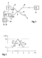
- Fig. 1 shows a measurement setup comprising a tunable light source 2, an optical power detector 4, an evaluation unit 20, an optical coupler 6, an optical termination 8 located nearby, e.g. in a measurement unit, and a remote optical element 10.
- Optical coupler 6 has four connections, wherein the first connection is connected over a first optical fiber with tunable light source 2, the second connector is connected over a second optical fiber with power detector 3, the third connector is connected over a third optical fiber with optical element 10 and the fourth connector is connected over a fourth optical fiber with termination 8.
- Termination 8 can be realized as any other non-reflective fiber end.
- the light from the fourth port can be used for other purposes, e.g.
- evaluation unit 20 is connected both with tunable light source 2 and optical detector 4 and possibly the termination 8, receiving a wavelength over time signal ⁇ (t), further also referred to as first information from tunable light source 2 and a power over time signal P(t) or a power ratio P(t) determined by the signals from detector 4 and termination 8 also referred to as second information from optical detector 4.
- Evaluation unit 20 comprises a processing unit 22 and a storage unit 24.
- Tunable light source 2 can be any kind of source that generates a light beam of with a narrow linewidth compared to the width of the wavelength dependence of the optical device, i.e. a beam with a sharp wavelength peak, wherein the wavelength can be varied or swept between a minimum value and a maximum value.
- a light source is used wherein the wavelength can be varied at high speed with a substantially constant variation speed.
- a tunable laser is used.
- Optical element 10 is preferably a Fiber Bragg Grating (FBG).
- FBG's are environmentally temperature stable and mechanically robust.
- an FBG is preferably used as temperature sensor located in a drill hole with high temperatures and difficult environmental conditions.
- optical coupler 6 may be replaced by an optical circulator connecting tunable light source 2, optical element 10 and detector 14 so that the light received from tunable light source 2 is directed to remote optical element 10 and the light received from remote device 10 is directed to detector 4.
- Tunable light source emits a first optical signal S1 over first fiber 12, coupler 6 and third fiber 16 to optical element 10.
- the wavelength is varied at a substantially constant first rate or speed from a minimum value to a maximum value according to a first function of the time.
- Optical element 10 reflects a portion of the incident signal back to detector 4 over third optical fiber 16, coupler 6 and second optical fiber 14.
- Detector 4 detects the power over the time of the first received signal R1.
- tunable light source emits second optical signal S2 and detector 4 accordingly detects the power of the second received signal R2.
- the wavelength is varied at a substantially constant second rate or speed from the maximum value back to the minimum value wherein the first and second rate have the same absolute value and different signs.
- Evaluation unit 20 receives from tunable light source 2 first information ⁇ (t) that refers to the actual wavelength of the emitted light at emission time. Therefore tunable laser 2 comprises a wave meter that measures the wavelength of the emitted light and sends this information to evaluation unit 4. Alternatively to the use of a wave meter, first information ⁇ (t) can be derived on the base of control signals that are used for controlling tunable light source 2. Further, evaluation unit 20 receives from detector 4 second information that refers to the power of the detected signal at receiving time. Evaluation unit 20 combines or relates both first and second information into a function of the power of the received optical signal over the wavelength of the emitted signal. This is carried out for each of the two measurements and thus two power functions over wavelength are determined.
- both functions of the power over the wavelength are similar since characteristics of optical element do not change significantly during the measurement.
- the emission time differs from the receiving time. This results in a time shift between both information P(t) and ⁇ (t) and thus in a wavelength shift of the functions of the power over wavelength depending on the variation of the wavelength. Since the variations are inverse to each other, the first wavelength shift has a same absolute value and an opposite direction compared to the second wavelength shift.
- a combination of both functions e.g. a superposition, eliminates the wavelength shifts of both measurements.
- a start signal at the emission start can be transmitted from the light source to the evaluation unit.
- Evaluation unit 10 then calculates the wavelength over time information on the base of the start time, the starting wavelength and a determined wavelength variation (sweep speed).
- wavelength variation has to be known very precisely in evaluation unit 10,
- the optical element 10 has a defined wavelength characteristics that determines the portion reflected to detector 4.
- the wavelength characteristics of optical element 10 change depending on the environmental temperature.
- Evaluation unit 20 determines the temperature on the base of the combination of the two functions and a reference function. Further details are described under Fig.3.
- Fig.2 shows a diagram with exemplary wavelength over time functions F1, further referred to as variation functions F1 and F2 for first and second optical signals S1 and S2 described under Fig.1.
- the time is depicted in seconds (s) and at the y-axis or ordinate, the wavelength is depicted in nanometer (nm).
- First variation function F1 is a curve at a constant wavelength rate between a first point defined by 1s and minimum wavelength ⁇ 1 at 1500 nm and a second point defined by 2s and a maximum wavelength ⁇ 2 at 1600 nm.
- Second variation function F2 is a curve at a constant wavelength rate between the second point and a third point defined by 3 s and minimum wavelength ⁇ 1 at 1500 nm.
- the first wavelength rate or speed C1 is derived from the ratio between a first wavelength difference ⁇ 1 over an infinitesimal time distance ⁇ T within the first time period between 1 sand 2s.
- the second wavelength rate or speed C2 is derived from the ratio between a second wavelength difference ⁇ 2 over the infinitesimal time distance ⁇ T within the second time period between 2s and 3s.
- both speeds have the same absolute value of 100 nm/s ad different signs.
- Fig.3 shows exemplary measurement results.
- a wavelength ⁇ is depicted, and at the ordinate, a power over wavelength P( ⁇ ) is depicted.
- a first result function P1 and a second result function P2 stretch between minimum wavelength ⁇ 1 and maximum wavelength ⁇ 2, both exhibiting two prominent peaks PK1 and PK2.
- First result function P1 differs from second result function P2 only in that they are shifted to each other with a wavelength shift ⁇ .
- Result functions P1 and P2 correspond to variation functions F1 and F2 of Fig.2.
- a defined number of peaks PK1 and PK2 might occur as power result. However, it is not necessary to evaluate the whole result functions.
- One characteristic peak is chosen for further evaluation.
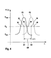
- Fig.4 therefore shows a part of the diagram of Fig.3 exemplary focusing on the first peak PK1.
- the result functions are drafted out of scale for better demonstrating the evaluation of center val ues G1, G2 and GR. Further, a horizontal line assigned to a constant power value Pm is depicted wherein Pm is the medium power between a minimum power Pmin and maximum power Pmax.
- First and second center values G1 and G2 are determined by establishing first two intersection points 30 and 34 and second two intersection points 36 and 40 and each taking the medium 32 and 36 between said pairs of intersection points.
- the distance between the center values is similar to the wavelength shift ⁇ of Fig. 3.
- the resulting center value GR is determined as the medium between both the fist center value G1 and the second center value G2.
- the measured results can further increase the measurement accuracy.
Abstract
Description
- The present invention relates to a determination of a physical state of an optical device by measuring a response signal.
- Optical devices showing response characteristics dependent on a physical state, e.g. the temperature, pressure, strain or mechanical force are widely used within optical systems. Often, such characteristics variations are unwanted and thus measurements are taken to reduce the effects of the variations or to measure such variations.
- Optical devices with wavelength dependent characteristics, especially Fiber Bragg Gratings (FBG), Fabry Perot Filters or Etalons, are employed in a variety of engineering and environmental sensing applications. The wavelength response characteristics of those devices depend on their physical states caused by environmental conditions at those devices. Changes of the physical state can therefore be determined by analyzing a returned signal.
- US-A-6,449,047 discloses a tunable laser with an accurately calibrated wavelength output which can be rapidly scanned or swept over a selected wavelength band. Such lasers may generate wavelengths in the 1550 nm range and can be swept over about 50 nm. These lasers are used as components of sensor interrogator systems, which determine the power of reflected or transmitted by Fiber Bragg Gratings (FBG) depending on the wavelength of an incident beam.
- It is an object of the invention to provide an improved determination of a physical state of a remote optical device by means of measuring signals returned from the remote device. The object is solved by the independent claims. Preferred embodiments are shown by the dependent claims.
- A physical state having influence on the reflection characteristics, e.g. temperature, pressure, strain or a mechanical force, can in principle be determined by measuring a second optical property of a return signal in dependence of a first optical property of the corresponding incident beam, wherein the first optical property is varied during the measurement over a determined range, This physicals property can e.g. be determined by comparing this result with reference results. However, it is difficult to measure the first optical property at the second optical property at exactly the same time. Time shifts between said properties lead to wrong comparison results.
- According to the present invention, at least two subsequent measurements are executed. Therefore, a first optical signal is transmitted to the remote device, wherein a first optical property of said first signal is varied according to a first function of the time. A second optical property of the first response signal is measured over the time and a function between the second optical property of the response signal and he first optical property of the transmitted optical signal is established; i.e. the second optical property is determined as function of the first optical property. Further, a second optical signal is transmitted to the remote device, wherein the first optical property of said signal is varied according to a second function of the time that is different from the first function of time. The second optical property of the corresponding second response signal is measured and again a function between the second optical property of the response signal and the first optical property of the transmitted optical signal is established.
- Due to time delay effects in determining the second optical property the functions show each a shift between the first and the second optical property that is depending on the variation functions. The functions are combined such, that the time shifts of both measurements counteract each other and in the best case cancel out each other. Thus, for an optimum choice of variation functions, the determination of the physical state is substantially free from deviations due to said time shift effects of single measurements.
- The invention has the advantage, that measurements of the first optical property over the time and the seconds optical property over the time can be related to each other without caring about delays or shifts, e.g. delays due to a propagation time of the optical signal or an unknown detection or processing time within a measurement setup. There is no complicated device necessary for adjusting those property functions to each other.
- In an embodiment of the invention a combination of the first and the second function is performed by determining a first center value of at least a part of the first function and a second center value of at least part of the second function and determining a resulting center value in dependence of said first and second center values.
- In a further embodiment, the first and second function of time are chosen to describe each a substantially linear relation between the first optical property resulting in substantially constant variation speeds, also referred to as sweep speeds, wherein the variation speeds have the same absolute value and different signs. In this case the time delay effects result in wavelength shifts with the same absolute value and different signs for both functions. Thus, in the resulting center value determined by the average value of both single center values, no resulting wavelength shift occurs; i.e. through the combination of both measurements, the wavelength shifts are eliminated.
- Alternatively, the resulting center value is determined by superimposing both first and second measurements results and determining the center value of the superimposed measurements.
- In a further embodiment, said first and second function of time describe each a substantially linear relationship between the first optical property and the time resulting in substantially constant variation speeds but do not necessarily have the same absolute value and different signs. The center value is generally determined according to the following equation:
C - In a further embodiment, a comparison is carried out between the resulting center value and a reference center value derived from known reflection characteristics of the remote device at a reference physical state. The physical state of the remote device is preferably determined by evaluating the distance between the resulting center value and the reference center value and wherein the physical state is determined as function of an absolute value assigned to the reference center value and a relative value dependent on the distance between said centers.
- The center values representing characteristic values of the physical state of the device can be determined by various methods. One method for determining a center value is to determine the midpoint by establishing each two intersection points of the corresponding part of a function of the second optical property over the first optical property (e.g. a region around a characteristic function peak) and a horizontal line representing a constant value, e.g. a so-called 3dB line representing a medium value between the minimum and maximum values of the measured second optical property. The midpoint is determined by the mid value between the two intersection points.
- Alternatively, a center value is determined by a convolution between a corresponding function of said corresponding function part and a reference function.
- Further alternatively, a center of mass, also known as center of gravity or centroid, is determined by calculating the first momentum of that part of said corresponding function part that is above a defined fraction of the maximum value of the second optical property (e.g. a 3dB horizontal line).
- Further alternatively, the center value is determined by taking the maximum of said corresponding function part.
- In a further embodiment, the first optical property is the wavelength of the first and second optical signal and the second physical property is the power of the signals returned from the remote device. Alternatively, the first optical property is the polarization of the emitted optical signals, wherein the rotation an/or the polarization plane are varied by a function of time.
- In a further preferred embodiment, the remote device is one of a Fiber Bragg Grating, a Fabry Perot Interferometer or a Michelson Interferometer.
- The physical state to be measured can be any environmental conditions, e.g. temperature, pressure, strain or a mechanical force, that is applied to the remote device.
- In a further embodiment, the evaluation for determining an optical state of a remote optical device is carried out in an evaluation unit, that receives first optical property information about each a first and a second optical signal coupled to a remote device, second optical property information about each a correspondingly first and a second returned optical signals from the remote device and relates the first and the second information for each the first and the second measurement into functions of the second optical property over the first optical property. The physical state is then determined by combining the established functions such that the effects of time shifts within the first and the second function are at least significantly reduced.
- The invention can be partly or entirely embodied or supported by one or more suitable software programs, which can be stored on or otherwise provided by any kind of data carrier, and which might be executed in or by any suitable data processing unit. Software programs or routines are preferably applied for the evaluation of measurement results in the evaluation unit. The evaluation unit can be a computer or an oscilloscope comprising a processing unit and a storage device. The storage device stores both reference data for performing comparisons between measured values and reference values an a software program for performing the reception of information from the devices of a setup for measuring the physical state, the establishment of relating the optical properties to each other and the comparison between measured data and reference data.
- Other objects and many of the attendant advantages of the present invention will be readily appreciated and become better understood by reference to the following detailed description when considering in connection with the accompanied drawing(s). Features that are substantially or functionally equal or similar will be referred to with the same reference sign(s).
- Fig. 1
- shows a measurement setup according to the invention with an evaluation unit according to the invention,
- Fig.2
- shows a diagram depicting exemplary functions of wavelength over time for signals generated by a tunable light source,
- Fig.3
- shows a diagram depicting exemplary functions of power over wavelength for two detected signals determined in the evaluation unit and
- Fig.4
- shows a part of the diagram of Fig.3 with each one peak of the functions and center values of them.
- Fig. 1 shows a measurement setup comprising a tunable
light source 2, anoptical power detector 4, anevaluation unit 20, anoptical coupler 6, anoptical termination 8 located nearby, e.g. in a measurement unit, and a remoteoptical element 10.Optical coupler 6 has four connections, wherein the first connection is connected over a first optical fiber with tunablelight source 2, the second connector is connected over a second optical fiber withpower detector 3, the third connector is connected over a third optical fiber withoptical element 10 and the fourth connector is connected over a fourth optical fiber withtermination 8.Termination 8 can be realized as any other non-reflective fiber end. The light from the fourth port can be used for other purposes, e.g. for measuring the power or wavelength or both of it of thesource 2 Further,evaluation unit 20 is connected both with tunablelight source 2 andoptical detector 4 and possibly thetermination 8, receiving a wavelength over time signal λ(t), further also referred to as first information from tunablelight source 2 and a power over time signal P(t) or a power ratio P(t) determined by the signals fromdetector 4 andtermination 8 also referred to as second information fromoptical detector 4.Evaluation unit 20 comprises aprocessing unit 22 and astorage unit 24. - Tunable
light source 2 can be any kind of source that generates a light beam of with a narrow linewidth compared to the width of the wavelength dependence of the optical device, i.e. a beam with a sharp wavelength peak, wherein the wavelength can be varied or swept between a minimum value and a maximum value. Preferably, a light source is used wherein the wavelength can be varied at high speed with a substantially constant variation speed. As preferred light source, a tunable laser is used.Optical element 10 is preferably a Fiber Bragg Grating (FBG). - FBG's are environmentally temperature stable and mechanically robust. Thus, an FBG is preferably used as temperature sensor located in a drill hole with high temperatures and difficult environmental conditions.
- Alternatively,
optical coupler 6 may be replaced by an optical circulator connecting tunablelight source 2,optical element 10 anddetector 14 so that the light received from tunablelight source 2 is directed to remoteoptical element 10 and the light received fromremote device 10 is directed todetector 4. - Tunable light source emits a first optical signal S1 over
first fiber 12,coupler 6 andthird fiber 16 tooptical element 10. During the emission of the first optical signal, the wavelength is varied at a substantially constant first rate or speed from a minimum value to a maximum value according to a first function of the time.Optical element 10 reflects a portion of the incident signal back todetector 4 over thirdoptical fiber 16,coupler 6 and secondoptical fiber 14.Detector 4 detects the power over the time of the first received signal R1. Subsequently after termination ofoptical signal 1, tunable light source emits second optical signal S2 anddetector 4 accordingly detects the power of the second received signal R2. During the emission of the second optical signal, the wavelength is varied at a substantially constant second rate or speed from the maximum value back to the minimum value wherein the first and second rate have the same absolute value and different signs. -
Evaluation unit 20 receives from tunablelight source 2 first information λ(t) that refers to the actual wavelength of the emitted light at emission time. Thereforetunable laser 2 comprises a wave meter that measures the wavelength of the emitted light and sends this information toevaluation unit 4. Alternatively to the use of a wave meter, first information λ(t) can be derived on the base of control signals that are used for controlling tunablelight source 2. Further,evaluation unit 20 receives fromdetector 4 second information that refers to the power of the detected signal at receiving time.Evaluation unit 20 combines or relates both first and second information into a function of the power of the received optical signal over the wavelength of the emitted signal. This is carried out for each of the two measurements and thus two power functions over wavelength are determined. - As long as no time delay occurs between sending optical signals S1 or S2 and detecting the power of received optical signals R1 or R2, both functions of the power over the wavelength are similar since characteristics of optical element do not change significantly during the measurement. However, with increasing distance between tunable
light source 2 andoptical element 10, the emission time differs from the receiving time. This results in a time shift between both information P(t) and λ(t) and thus in a wavelength shift of the functions of the power over wavelength depending on the variation of the wavelength. Since the variations are inverse to each other, the first wavelength shift has a same absolute value and an opposite direction compared to the second wavelength shift. Thus, a combination of both functions, e.g. a superposition, eliminates the wavelength shifts of both measurements. - Alternatively to the wavelength determination in the tunable light source, a start signal at the emission start can be transmitted from the light source to the evaluation unit.
Evaluation unit 10 then calculates the wavelength over time information on the base of the start time, the starting wavelength and a determined wavelength variation (sweep speed). However, wavelength variation has to be known very precisely inevaluation unit 10, - The
optical element 10 has a defined wavelength characteristics that determines the portion reflected todetector 4. The wavelength characteristics ofoptical element 10 change depending on the environmental temperature.Evaluation unit 20 determines the temperature on the base of the combination of the two functions and a reference function. Further details are described under Fig.3. - Fig.2 shows a diagram with exemplary wavelength over time functions F1, further referred to as variation functions F1 and F2 for first and second optical signals S1 and S2 described under Fig.1. At the x-axis or abscissa, the time is depicted in seconds (s) and at the y-axis or ordinate, the wavelength is depicted in nanometer (nm). First variation function F1 is a curve at a constant wavelength rate between a first point defined by 1s and minimum wavelength λ1 at 1500 nm and a second point defined by 2s and a maximum wavelength λ2 at 1600 nm. Second variation function F2 is a curve at a constant wavelength rate between the second point and a third point defined by 3 s and minimum wavelength λ1 at 1500 nm.
- The first wavelength rate or speed C1 is derived from the ratio between a first wavelength difference Δλ1 over an infinitesimal time distance ΔT within the first time period between 1 sand 2s. The second wavelength rate or speed C2 is derived from the ratio between a second wavelength difference Δλ2 over the infinitesimal time distance ΔT within the second time period between 2s and 3s. By way of example, both speeds have the same absolute value of 100 nm/s ad different signs.
- Decreasing the sweep speed results in more accurate matching of the wavelength and the power on the one hand but in an increasing noise on the other hand due to variations of the transmission properties of the optical fiber. Moreover, if the sweeping speed is slow, dynamic changes of the physical property within the sweeping time have possibly to be taken into account. In addition the update rate of the measurement is slower for a slower sweep speed.
- Fig.3 shows exemplary measurement results. At the abscissa, a wavelength λ is depicted, and at the ordinate, a power over wavelength P(λ) is depicted. A first result function P1 and a second result function P2 stretch between minimum wavelength λ1 and maximum wavelength λ2, both exhibiting two prominent peaks PK1 and PK2. First result function P1 differs from second result function P2 only in that they are shifted to each other with a wavelength shift Δλ. Result functions P1 and P2 correspond to variation functions F1 and F2 of Fig.2.
- Depending on the characteristics of the
optical element 10, a defined number of peaks PK1 and PK2 might occur as power result. However, it is not necessary to evaluate the whole result functions. One characteristic peak is chosen for further evaluation. Fig.4 therefore shows a part of the diagram of Fig.3 exemplary focusing on the first peak PK1. The result functions are drafted out of scale for better demonstrating the evaluation of center val ues G1, G2 and GR. Further, a horizontal line assigned to a constant power value Pm is depicted wherein Pm is the medium power between a minimum power Pmin and maximum power Pmax. - First and second center values G1 and G2 are determined by establishing first two
intersection points intersection points - An advantage of considering only a part of the result function is that only a reduced amount of data needs to be captured and stored in
evaluation unit 4 - Repeatedly sweeping the wavelength of the emitted light forwards and backwards and averaging, or otherwise statistically analyzing, the measured results can further increase the measurement accuracy.
Claims (16)
- A method of determining a physical state of an optical device (10) with the steps of:coupling a first optical signal (S1) to the optical device (10), wherein a first optical property (λ(t)) of said first optical signal (S1) is varied according to a first function over the time (F1),measuring a second optical property (P(t)) over the time of a first response signal (R1) returning from the optical device (10) in response to the first optical signal (S1) and establishing a first result function (P1) of said second optical property in dependence of the first optical property of the first optical signal (S1),coupling a second optical signal (S2) to the optical device (10), wherein the first optical property (λ(t)) of said second optical signal (S2) is varied according to a second function of the time (F2) that is different from the first function over the time (F1),measuring the second optical property (P(t)) over the time of a second response signal (R2) returning from the optical device (10) in response to the second optical signal (S2) and establishing a second result function (P2) of said second optical property in dependence of the first optical property of the second optical signal (S2), anddetermining the physical state based on a combination of the first and the second result functions (P1, P2).
- The method of claim 1, wherein a combination of the first and the second result functions (P1, P2) is performed by determining a first center value (G1) of at least a part of the first function and a second center value (G2) of at least a part of the second function and determining a resulting center value (GR) in dependence of said first and second center values (G1, G2).
- The method of claim 2, wherein said first and second function of time (F1, F2) are chosen to describe each a substantially linear relation between the first optical property resulting in substantially constant variation speeds (C1, C2), wherein the variation speeds have the same absolute value and different signs and wherein the resulting center value (GR) is determined by the average of both the center values (G1, G2).
- The method of claim 1, wherein said first and second function of time (F1, F2) are chosen to describe each a substantially linear relation between the first optical property and the time resulting in substantially constant variation speeds (C1, C2), wherein the variation speeds have the same absolute value and different signs and wherein the resulting center value (GR) is determined by superimposing both first and second measurements results and determining the center value of the superimposed measurements.
- The method of claim 2, wherein said first and second function of time (F1, F2) describe each a substantially linear relationship between the first optical property and the time resulting in substantially constant variation speeds (C1, C2) and wherein the resulting center value (GR) is determined according to the following equation:
- The method of claim 2 or any one of the above claims, wherein a comparison is carried out between the resulting center value (GR) and a reference center value derived from known reflection characteristics of the remote device at a reference physical state.
- The method according to claim 6, wherein the physical state is determined by evaluating the difference between the resulting center value (GR) and the reference center value and wherein the physical state is determined in dependence of the reference physical state and the distance between said centers.
- The method of claim 2 or any one of the above claims, wherein at least one of: the first center value (G1), the second center value (G2) and the resulting center value (GR) is determined by evaluating two intersection points (30, 32) of the corresponding function of the second optical property over the first optical property and a horizontal line describing a defined constant value (Pm) over the first optical property (λ) and further determining the mid-point (32) between said intersection points.
- The method of claim 2 or any one of the above claims, wherein at least one of: the first center value (G1), the second center value (G2) and the resulting center value (GR) is determined by evaluating the center of mass of that part of the corresponding function of the second optical property over the first optical property, that is above a horizontal line describing a defined constant value (Pm) over the first optical property (λ).
- The method of claim 2 or any one of the above claims, wherein at least one of: the first center value (G1), the second center value (G2) and the resulting center value (GR) is determined by a convolution between a result function (P1, P2) of the second optical property over the first optical property and a reference function.
- The method of claim 1 or any one of the above claims, wherein the first optical property is the wavelength of the first and second optical signal (S1, S2) and the second physical property is the power of the signals returned from the remote device.
- The method of claim 11, wherein the remote device is one of: a Fiber Bragg Grating, a Fabry Perot Interferometer, or a Michelson Interferometer.
- The method of claim 1 or any one of the above claims, wherein the physical state is one of: the temperature, the pressure, the strain and the mechanical force.
- A evaluation unit (20) for determining an optical state of an optical device (10), comprisinga first input adapted for receiving first optical property information (λ(t)) about each a first and a second optical signal coupled to a optical device (10),a second input adapted for receiving second optical property information (P(t)) about each a correspondingly first and a second returned optical signals from the optical device (10),a processing unit adapted for relating the first and the second information for each the first and the second measurement and further adapted for determining the physical state based on a combination of the first and the second result functions (P1, P2).
- A measurement setup adapted for determining an optical property of an optical device (10), comprising:A tunable light source (2) adapted for emitting a first and a second optical signal (S1, S2) with each an optical property variation over the time,an optical device (10) adapted for receiving said first and second optical signal and returning corresponding first and second response signals (R1, R2),an optical detector (4) for determining the optical power of the detected first and second response signals (R1, R2),optical guides (12, 14, 16) for optically connecting each the tunable light source (2) and the optical detector (4) to the optical device (10), andan evaluation unit (20) of claim 13 connected to the tunable light source (2) for receiving the first information (λ(t)) and to the optical detector (4) for receiving the second information (P(t)).
- A software program or product, preferably stored on a data carrier, for executing in an evaluation unit the following steps, when run on a data processing system such as a computer:receiving first information (λ(t)) about a first optical property of at least two emitted optical signals (S1, S2),receiving second information (P(t)) about a second optical property of two detected corresponding signals (R1, R2) returned from an optical device (10),relating the first and the second information to each other into each a function for each of the optical signals (S1, S2) and determining a resulting center value (GR) on the base of the first and the second result functions (P1, P2).
Priority Applications (3)
| Application Number | Priority Date | Filing Date | Title |
|---|---|---|---|
| EP04101584A EP1586879A1 (en) | 2004-04-16 | 2004-04-16 | Determination of a physical parameter by means of an optical device |
| US11/105,697 US7312435B2 (en) | 2004-04-16 | 2005-04-14 | Determination of a physical state of an optical device |
| JP2005117735A JP2005308744A (en) | 2004-04-16 | 2005-04-15 | Judgement of physical condition of optical element |
Applications Claiming Priority (1)
| Application Number | Priority Date | Filing Date | Title |
|---|---|---|---|
| EP04101584A EP1586879A1 (en) | 2004-04-16 | 2004-04-16 | Determination of a physical parameter by means of an optical device |
Publications (1)
| Publication Number | Publication Date |
|---|---|
| EP1586879A1 true EP1586879A1 (en) | 2005-10-19 |
Family
ID=34928969
Family Applications (1)
| Application Number | Title | Priority Date | Filing Date |
|---|---|---|---|
| EP04101584A Withdrawn EP1586879A1 (en) | 2004-04-16 | 2004-04-16 | Determination of a physical parameter by means of an optical device |
Country Status (3)
| Country | Link |
|---|---|
| US (1) | US7312435B2 (en) |
| EP (1) | EP1586879A1 (en) |
| JP (1) | JP2005308744A (en) |
Cited By (1)
| Publication number | Priority date | Publication date | Assignee | Title |
|---|---|---|---|---|
| DE102015212962A1 (en) * | 2015-07-10 | 2017-01-12 | Deutsches Zentrum für Luft- und Raumfahrt e.V. | Method for determining spectral characteristics of an optical signal of a test object |
Families Citing this family (3)
| Publication number | Priority date | Publication date | Assignee | Title |
|---|---|---|---|---|
| US8379297B2 (en) | 2006-05-30 | 2013-02-19 | Weatherford/Lamb, Inc. | Wavelength swept light source and filter based on sweep function, and its method of operation |
| US8552360B2 (en) * | 2006-05-30 | 2013-10-08 | Weatherford/Lamb, Inc. | Wavelength sweep control |
| CN112834072B (en) * | 2021-02-08 | 2021-09-24 | 广东海洋大学 | Michelson interference optical fiber temperature sensor for detecting stripe contrast change |
Citations (3)
| Publication number | Priority date | Publication date | Assignee | Title |
|---|---|---|---|---|
| US4632551A (en) * | 1984-06-11 | 1986-12-30 | Litton Systems, Inc. | Passive sampling interferometric sensor arrays |
| US5798521A (en) * | 1996-02-27 | 1998-08-25 | The United States Of America As Represented By The Administrator Of The National Aeronautics And Space Administration | Apparatus and method for measuring strain in bragg gratings |
| US6204920B1 (en) * | 1996-12-20 | 2001-03-20 | Mcdonnell Douglas Corporation | Optical fiber sensor system |
Family Cites Families (5)
| Publication number | Priority date | Publication date | Assignee | Title |
|---|---|---|---|---|
| IT1262407B (en) * | 1993-09-06 | 1996-06-19 | Finmeccanica Spa | INSTRUMENTATION USING INTEGRATED OPTIC COMPONENTS FOR DIAGNOSTICS OF PARTS WITH FIBER OPTIC SENSORS INCLUDED OR FIXED ON THE SURFACE. |
| US5696858A (en) * | 1996-08-01 | 1997-12-09 | The Texas A&M University System | Fiber Optics apparatus and method for accurate current sensing |
| US6449047B1 (en) | 1998-11-13 | 2002-09-10 | Micron Optics, Inc. | Calibrated swept-wavelength laser and interrogator system for testing wavelength-division multiplexing system |
| US6571027B2 (en) * | 1999-10-07 | 2003-05-27 | Peter W. E. Smith | Method and devices for time domain demultiplexing of serial fiber bragg grating sensor arrays |
| FR2826448B1 (en) * | 2001-06-21 | 2005-10-14 | Commissariat Energie Atomique | DIFFERENTIAL MEASUREMENT SYSTEM BASED ON THE USE OF BRAGG NETWORK PAIRS |
-
2004
- 2004-04-16 EP EP04101584A patent/EP1586879A1/en not_active Withdrawn
-
2005
- 2005-04-14 US US11/105,697 patent/US7312435B2/en not_active Expired - Fee Related
- 2005-04-15 JP JP2005117735A patent/JP2005308744A/en active Pending
Patent Citations (3)
| Publication number | Priority date | Publication date | Assignee | Title |
|---|---|---|---|---|
| US4632551A (en) * | 1984-06-11 | 1986-12-30 | Litton Systems, Inc. | Passive sampling interferometric sensor arrays |
| US5798521A (en) * | 1996-02-27 | 1998-08-25 | The United States Of America As Represented By The Administrator Of The National Aeronautics And Space Administration | Apparatus and method for measuring strain in bragg gratings |
| US6204920B1 (en) * | 1996-12-20 | 2001-03-20 | Mcdonnell Douglas Corporation | Optical fiber sensor system |
Cited By (2)
| Publication number | Priority date | Publication date | Assignee | Title |
|---|---|---|---|---|
| DE102015212962A1 (en) * | 2015-07-10 | 2017-01-12 | Deutsches Zentrum für Luft- und Raumfahrt e.V. | Method for determining spectral characteristics of an optical signal of a test object |
| DE102015212962B4 (en) | 2015-07-10 | 2022-03-03 | Deutsches Zentrum für Luft- und Raumfahrt e.V. | Method for determining spectral characteristics of an optical signal of a measurement object |
Also Published As
| Publication number | Publication date |
|---|---|
| US7312435B2 (en) | 2007-12-25 |
| JP2005308744A (en) | 2005-11-04 |
| US20050230607A1 (en) | 2005-10-20 |
Similar Documents
| Publication | Publication Date | Title |
|---|---|---|
| Hotate et al. | Synthesis of optical-coherence function and its applications in distributed and multiplexed optical sensing | |
| CA2509187C (en) | Optical wavelength determination using multiple measurable features | |
| US7561276B2 (en) | Demodulation method and apparatus for fiber optic sensors | |
| US8477296B2 (en) | Opto-electronic signal processing methods, systems, and apparatus for optical sensor interrogation | |
| US7292345B2 (en) | Fibre-optic interferometric remote sensor | |
| US7573021B2 (en) | Method and apparatus for multiple scan rate swept wavelength laser-based optical sensor interrogation system with optical path length measurement capability | |
| US7564562B2 (en) | Method for demodulating signals from a dispersive white light interferometric sensor and its application to remote optical sensing | |
| EP2839554B1 (en) | Frequency tunable laser system | |
| US6118534A (en) | Sensor and method for measuring changes in environmental conditions | |
| US10571321B2 (en) | Device for measuring fluid parameters, a method for measuring fluid parameters and a computer program product | |
| US7312435B2 (en) | Determination of a physical state of an optical device | |
| CN113654580A (en) | Optical frequency domain reflection system capable of simultaneously measuring temperature and strain | |
| US11162821B2 (en) | Fibre optic sensing device | |
| Sandmann et al. | Simultaneous Temperature and Acoustic Sensing with Coherent Correlation OTDR | |
| EP1367376A1 (en) | Method and apparatus for measuring chromatic dispersion | |
| JP6082313B2 (en) | Distance measuring apparatus and method for optical axis adjustment | |
| KR101844031B1 (en) | measuring system of OFDR and mearsuring method thereof | |
| JP6141433B2 (en) | Optical fiber sensing optical system and optical fiber sensing system | |
| US20220326005A1 (en) | Distributed Vibration Measuring Device and Method | |
| Won et al. | FMCW reflectometric optical fiber strain sensor | |
| JP2021043050A (en) | Optical sensor and physical amount measurement device | |
| Gornall et al. | Accurate wavelength interrogation of fiber Bragg grating sensors using Michelson interferometry | |
| Ames et al. | Multiplexed Fiber Laser Sensor System | |
| Murphy et al. | Characterization and testing of materials using multichannel fiber sensor systems |
Legal Events
| Date | Code | Title | Description |
|---|---|---|---|
| PUAI | Public reference made under article 153(3) epc to a published international application that has entered the european phase |
Free format text: ORIGINAL CODE: 0009012 |
|
| AK | Designated contracting states |
Kind code of ref document: A1 Designated state(s): AT BE BG CH CY CZ DE DK EE ES FI FR GB GR HU IE IT LI LU MC NL PL PT RO SE SI SK TR |
|
| AX | Request for extension of the european patent |
Extension state: AL LT LV MK |
|
| 17P | Request for examination filed |
Effective date: 20060419 |
|
| AKX | Designation fees paid |
Designated state(s): DE FR GB |
|
| 17Q | First examination report despatched |
Effective date: 20061031 |
|
| RAP1 | Party data changed (applicant data changed or rights of an application transferred) |
Owner name: AGILENT TECHNOLOGIES, INC. |
|
| GRAP | Despatch of communication of intention to grant a patent |
Free format text: ORIGINAL CODE: EPIDOSNIGR1 |
|
| STAA | Information on the status of an ep patent application or granted ep patent |
Free format text: STATUS: THE APPLICATION IS DEEMED TO BE WITHDRAWN |
|
| 18D | Application deemed to be withdrawn |
Effective date: 20091031 |