EP1588640A1 - Length adjustment device of a strap, especially for a wristwatch strap - Google Patents
Length adjustment device of a strap, especially for a wristwatch strap Download PDFInfo
- Publication number
- EP1588640A1 EP1588640A1 EP04009671A EP04009671A EP1588640A1 EP 1588640 A1 EP1588640 A1 EP 1588640A1 EP 04009671 A EP04009671 A EP 04009671A EP 04009671 A EP04009671 A EP 04009671A EP 1588640 A1 EP1588640 A1 EP 1588640A1
- Authority
- EP
- European Patent Office
- Prior art keywords
- cable
- pulley
- adjustment
- strip
- wheel
- Prior art date
- Legal status (The legal status is an assumption and is not a legal conclusion. Google has not performed a legal analysis and makes no representation as to the accuracy of the status listed.)
- Granted
Links
Images


Classifications
-
- A—HUMAN NECESSITIES
- A44—HABERDASHERY; JEWELLERY
- A44C—PERSONAL ADORNMENTS, e.g. JEWELLERY; COINS
- A44C5/00—Bracelets; Wrist-watch straps; Fastenings for bracelets or wrist-watch straps
- A44C5/18—Fasteners for straps, chains or the like
- A44C5/22—Fasteners for straps, chains or the like for closed straps
Definitions
- the present invention relates to a device for adjusting the length of a particularly, but not exclusively, a watch strap lengthening or shortening thereof as desired by the wearer.
- the tightening of the bracelet on the wearer's wrist must therefore be able to be adjusted precisely to place the watch in good conditions of measurement of the pulse and maintained in these setting conditions even under working conditions difficult as during a run during which the bracelet is subjected to Shocks and vibrations. During these efforts, the wrist tending to inflate, the wearer must be able to decrease the tightening of the bracelet without losing the measured.
- Document CH-A-665327 describes a device for attaching a bracelet to a watch case for wrapping the bracelet around a pillar and so reduce or lengthen the size of the bracelet.
- This document does not show mechanism for locking the winding or unwinding of the bracelet, but only one or more bosses creating an obstacle to the exit of the link of the pillar.
- This device does not allow precise adjustment of the size of the bracelet, does not ensure the maintaining such a setting during use and is therefore not suitable for previously mentioned.
- Document DE-U-20020360 discloses a device for adjusting the length of a watch strap. Both ends of the bracelet are attached to a winding shaft, housed in a two-piece housing, shaft that can be rotated thanks to a wheel, to be fixed in its position and to be released thanks to a mechanism decoupling.
- the winding shaft comprises a disc which presents on its upper surface a notching which cooperates with a corresponding notch on a disk attached to and under the wheel, this last disk being surrounded by a toothed ring provided with external toothing in which a ratchet of blocking solidarity of the housing.
- Means for centering the device as well as return means in the notched position of the device are further provided.
- This device with its many mechanical parts is complicated, expensive and, given the large number of parts involved, subject to disturbances. In Furthermore, this device does not guarantee a controlled unwinding of the bracelet but only a release of the winding shaft that can allow unrolling the bracelet. In addition, this device acts directly on the bracelet by wrapping it around of the winding shaft. This device is therefore limited to certain types of bracelets of watch, that is, bracelets that can be easily rolled up, and has the disadvantage of damaging the bracelet by its direct action on it.
- the problem underlying the present invention is therefore to be able to perform a bidirectional adjustment of the length of a strip in a fast and precise way, this setting must be maintained under all conditions of use.
- the present invention proposes a device for adjusting the length of a strip, this strip comprising two parts close to or distant from each other, characterized in that it comprises a set of adjusting the length of the band, worn by the first part and comprising at least one cable, this cable connecting the first part with the second, this adjustment assembly comprising means for actuating the adjustment by the operator, a control pulley secured to this means to which is fixed one of ends of the cable and around which wraps a portion of the cable, this pulley being associated with locking means capable of locking it in rotation in a plurality of adjustment positions.
- the actuating means may be a wheel, on the one hand movable axially between a locking position and an adjustment position, the wheel being pushed into its locking position by an elastic means, and other rotating moving part to adjust the length of the belt.
- the adjustment pulley is housed inside a hollow body integral with the part and comprises fins, said fins cooperating with means of locking provided on the body which has at its upper part notches adapted to the fins for receiving them in order to block the rotation of the adjusting pulley.
- This body may be formed of two parts fixed together immovable manner.
- the other end of the cable is attached to the first part of the tape and a portion of the intermediate area of the cable is received in the second part of slidably in it.
- a return auxiliary pulley can be provided on the second part of the band to redirect the cable to the first part.
- the present invention also relates to a watch bracelet with one of the length adjustment devices as described above.
- the cable 3 has one of its ends fixed on the part 1 in 3a and the other in the adjustment assembly 4, 5, 3 on the drum of the pulley 5 in the example shown. From each of these two ends, the cable 3 extends towards the part 2 in two branches substantially parallels terminated by a U or V shape where the cable passes through the Part 2.
- the part 2 is provided with an insert 8 comprising a channel 8a for the reception of the cable 3.
- the surface of the channel in which the cable preferably has a low coefficient of friction to facilitate the movement of the cable in this one. This surface may for example be coated a Teflon layer.
- the cable 3 can also be coated with such layer.
- FIGS. 2a and 2b respectively show a tense adjustment position and one of the possible relaxed adjustment positions obtained by the adjustment assembly 4, 5, 3.
- the wheel 4 has not been shown to allow to see the remainder of the adjustment assembly and in particular the cooperation of the adjusting pulley 5 and cable 3.
- the adjustment assembly comprises a pulley 5 around which wraps the cable 3.
- This figure illustrates the maximum winding position of the cable and therefore of maximum shortening of the bracelet with parts 1 and 2 of the bracelet attached.
- the adjusting pulley 5 has been rotated in the anti-clockwise and unrolled a portion of cable thus allowing to remove the parts 1 and 2 and therefore to lengthen the bracelet.
- the bracelet is then in a position relaxed adjustment. There are thus several relaxed adjustment positions, these positions corresponding to a more or less pronounced unwinding of the cable 3 of the adjustment pulley 5.
- the cable 3 has thus slid into the channel of the insert 8 of the part 2 of the bracelet, hence the need to use an insert 8 and a cable 3 with the weakest coefficient of friction possible.
- the pulley 5 comprises at its periphery of the fins 9 which cooperate with notches 9 'of the same shape arranged on the upper part 6 of a body 6 and 6 'included in part 1 of the bracelet to allow the insertion of these fins 9 in this upper part 6 and thus lock the adjusting pulley 5 in a setting position as will be described in detail below.
- these fins 9 can advantageously forming a guiding flange of the cable 3 during its winding and ensuring its holding around the adjusting pulley 5.
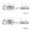
- Figures 3a and 3b describe the operation of the adjustment assembly according to the invention in the embodiment with a finned adjustment pulley 5 and a body with its upper part 6 having notches 9 'to realize the locking the adjustment set.
- the wheel 4 and the adjusting pulley 5 are integral and in their adjustment position can rotate to unroll or wind the cable 3 thus setting the length of the bracelet; moreover the wheel 4 and the adjusting pulley 5 are movable axially between a position where the wheel 4 is in the up position said position of rest and a position where the wheel 4 is in the low position called adjustment position.
- the wheel assembly 4 and adjustment pulley 5 is recalled by an elastic means, here a helical spring 7 extending between the lower surface of the wheel 4 and the lower part 6 'of the body 1, in its rest position.
- This set is partially housed in a body with upper 6 and lower 6 ' integral with the part 1 of the bracelet, a space being formed between the base of the lower part 6 'of the body and the lower part of the adjusting pulley 5 for allow the latter to move axially in the body.
- the wearer press the knob 4 which has the effect of pushing the adjusting pulley 5 in the body and to release the fins of the notches provided on the upper part 6 of the body.
- the pulley wheel assembly is then free to rotate and adjust the cable can be done.
- the adjustment pulley 5 can therefore be rotated to a position where its fins 9 will find themselves again in correspondence with the notches of the upper part 6 of the body: at this moment the wearer can release the pressure on the wheel 4, the elastic means 7 will recall the entire wheel-pulley in its rest position, that is to say with the wheel 4 in the high position and the fins 9 of the adjusting pulley 5 housed again in the notches of the upper part 6 of the body: the system of adjustment of the length of the bracelet will be blocked again.
- the wheel 4 can be made of a transparent material to allow the user easy alignment of the fins 9 of the adjusting pulley 5 with the corresponding notches in the upper part 6 of the body.
- This easy alignment can also be achieved with printed or embossed markers arranged on the wheel 4 and on the upper part 6 of the body.
- the adjustment device shown in the attached figures represents a first embodiment of the invention.
- the adjustment pulley comprises on one of its upper or lower faces concentric recesses for the receipt of a finger protruding from the first part of the band, this finger being introduced into one of the concentric recesses when the elastic means recalls the average means of actuation-adjusting pulley in its position of locking.
- the spring 7 may be replaced by a leaf spring disposed at the bottom of the housing of the part lower 6 'of the body for receiving the adjusting pulley 5, this spring recalling the adjusting pulley 5 upwards.
- notches were shown on the upper part 6 of the body but can be placed at other levels. It is even possible to plan a low rest position of the wheel 4 with a setting position with thumbwheel high by reversing the effect of the return means.
- the device of the The present invention makes it possible to obtain in a simple manner a precise and safe adjustment of the bandaged.
- this device can find an application in the case of a bracelet metal or it is better not to remove or add links.
- parts 1 and 2 of the band could form two particular links inserted into the chain of links, these two parts having for this purpose means of connection to the rest of the chain of links.
- the cable could for example cross several links to divide the spacing with the first part between several links.
- the bracelet is constituted by two son, preferably elastic, successively fitting the links, these two wires can be replaced by the cable associated with the set of adjustment according to the present invention.
- the setting could be distributed over the entire links by reducing the game between each of them which would not interfere aesthetics.
Abstract
Description
La présente invention concerne un dispositif de réglage de la longueur d'une bande, notamment mais pas exclusivement d'un bracelet de montre permettant un rallongement ou un raccourcissement de celui-ci selon le souhait du porteur.The present invention relates to a device for adjusting the length of a particularly, but not exclusively, a watch strap lengthening or shortening thereof as desired by the wearer.
Par exemple pour un bracelet de montre, lorsque les conditions climatiques font varier les paramètres du poignet, notamment en été quand celui-ci a tendance à gonfler, il est souvent nécessaire de rallonger le bracelet pour des raisons de confort.For example for a watch strap, when the weather conditions vary the parameters of the wrist, especially in summer when it tends to inflate, it is often necessary to lengthen the bracelet for reasons of comfort.
Dans le cas d'utilisation d'une montre à fonction multiples, par exemple un cardiofréquencemètre utilisant des capteurs placés dans le fond de la boíte de montre et devant venir en contact étroit avec le poignet du porteur, il est nécessaire de garantir un bon serrage lors de la prise de mesure, ce serrage devant être maintenu pendant toute l'opération du cardiofréquencemètre. En effet, comme de tels appareils réalisent généralement des diverses opérations telles que des moyennes de mesures à partir des valeurs de pouls mesurées pendant un temps donné, il est nécessaire d'assurer qu'aucune interruption de mesure ne vienne fausser la moyenne pour que la valeur affichée soit bien représentative de l'effort fourni pendant ledit temps donné.In the case of using a multi-function watch, for example a heart rate monitor using sensors placed in the bottom of the box of watch and having to come into close contact with the wrist of the wearer, it is necessary to guarantee a good tightening when taking measurements, this tightening must be maintained during the entire operation of the heart rate monitor. Indeed, as such devices generally perform various operations such as averages of measurements from pulse values measured over a period of time given, it is necessary to ensure that no interruption of measurement occurs distort the average so that the displayed value is representative of the effort provided during said given time.
Le serrage du bracelet sur le poignet du porteur doit donc pouvoir être réglé précisément pour placer la montre dans de bonnes conditions de mesure du pouls et maintenu dans ces conditions de réglage même dans des conditions de travail difficiles comme lors d'une course à pied pendant laquelle le bracelet est soumis à des chocs et des vibrations importants. Durant ces efforts, le poignet ayant tendance à gonfler, le porteur doit pouvoir diminuer le serrage du bracelet sans perdre la mesure.The tightening of the bracelet on the wearer's wrist must therefore be able to be adjusted precisely to place the watch in good conditions of measurement of the pulse and maintained in these setting conditions even under working conditions difficult as during a run during which the bracelet is subjected to Shocks and vibrations. During these efforts, the wrist tending to inflate, the wearer must be able to decrease the tightening of the bracelet without losing the measured.
De même, lors de l'utilisation normale de la montre, un serrage prononcé sur le poignet de l'utilisateur comme lors de prises de mesures n'est plus nécessaire et même indésirable pour des raisons de commodité : il existe donc un besoin de pouvoir modifier les conditions de serrage du bracelet selon l'utilisation de la montre cardiofréquencemètre ou analogue, cette modification devant se faire le plus facilement possible, notamment sans avoir besoin d'ôter la montre du poignet.Similarly, during normal use of the watch, a pronounced the wrist of the user as when taking measurements is no longer necessary and even undesirable for the sake of convenience: there is therefore a need for ability to modify the tightening conditions of the bracelet according to the use of the watch cardio-frequency meter or the like, this modification having to be done the most easily possible, especially without the need to remove the wrist watch.
Aucune solution technique satisfaisante à ces difficultés n'a été jusqu'à maintenant proposée. No satisfactory technical solution to these difficulties has been now proposed.
Le document CH-A-665327 décrit un dispositif d'attache d'un bracelet à un boítier de montre permettant d'enrouler le bracelet autour d'un pilier et ainsi de réduire ou de rallonger la taille du bracelet. Ce document ne montre pas de mécanisme de verrouillage de l'enroulement ou du déroulement du bracelet, mais seulement un ou des bossages créant un obstacle à la sortie du lien du pilier. Ce dispositif ne permet pas un réglage précis de la taille du bracelet, n'assure pas le maintien d'un tel réglage pendant l'utilisation et ne convient donc pas aux utilisations précédemment évoquées.Document CH-A-665327 describes a device for attaching a bracelet to a watch case for wrapping the bracelet around a pillar and so reduce or lengthen the size of the bracelet. This document does not show mechanism for locking the winding or unwinding of the bracelet, but only one or more bosses creating an obstacle to the exit of the link of the pillar. This device does not allow precise adjustment of the size of the bracelet, does not ensure the maintaining such a setting during use and is therefore not suitable for previously mentioned.
Le document DE-U-20020360 divulgue un dispositif pour le réglage de la longueur d'un bracelet de montre. Les deux extrémités du bracelet sont fixées à un arbre d'enroulement, logé dans un boítier en deux parties, arbre qui peut être tourné grâce à une molette, être fixé dans sa position et être libéré grâce à un mécanisme de découplage. Pour ce faire, l'arbre d'enroulement comporte un disque qui présente à sa surface supérieure un crantage qui coopère avec un crantage correspondant sur un disque fixé à et sous la molette, ce dernier disque étant entouré d'une couronne dentée munie d'une denture extérieure dans laquelle s'insère un cliquet de blocage solidaire du boítier. Des moyens pour le centrage du dispositif de même que des moyens de rappel en position crantée du dispositif sont en outre prévus.Document DE-U-20020360 discloses a device for adjusting the length of a watch strap. Both ends of the bracelet are attached to a winding shaft, housed in a two-piece housing, shaft that can be rotated thanks to a wheel, to be fixed in its position and to be released thanks to a mechanism decoupling. To do this, the winding shaft comprises a disc which presents on its upper surface a notching which cooperates with a corresponding notch on a disk attached to and under the wheel, this last disk being surrounded by a toothed ring provided with external toothing in which a ratchet of blocking solidarity of the housing. Means for centering the device as well as return means in the notched position of the device are further provided.
Ce dispositif avec ses nombreuses pièces mécaniques est compliqué, coûteux et, vu le grand nombre de pièces impliquées, sujet à des dérèglements. En outre, ce dispositif ne garantit pas un déroulement contrôlé du bracelet mais seulement une libération de l'arbre d'enroulement qui peut permettre de dérouler le bracelet. De plus, ce dispositif agit directement sur le bracelet en l'enroulant autour de l'arbre d'enroulement. Ce dispositif est donc limité à certains types de bracelets de montre, c'est-à-dire les bracelets qui peuvent être facilement enroulés, et a le désavantage d'endommager le bracelet par son action directe sur celui-ci.This device with its many mechanical parts is complicated, expensive and, given the large number of parts involved, subject to disturbances. In Furthermore, this device does not guarantee a controlled unwinding of the bracelet but only a release of the winding shaft that can allow unrolling the bracelet. In addition, this device acts directly on the bracelet by wrapping it around of the winding shaft. This device is therefore limited to certain types of bracelets of watch, that is, bracelets that can be easily rolled up, and has the disadvantage of damaging the bracelet by its direct action on it.
Le problème à la base de la présente invention est donc de pouvoir effectuer un réglage bidirectionnel de la longueur d'une bande de manière rapide et précise, ce réglage devant être maintenu dans toutes conditions d'utilisation.The problem underlying the present invention is therefore to be able to perform a bidirectional adjustment of the length of a strip in a fast and precise way, this setting must be maintained under all conditions of use.
Pour résoudre ce problème, la présente invention propose un dispositif de réglage de la longueur d'une bande, cette bande comprenant deux parties pouvant être rapprochées ou éloignées l'une de l'autre, caractérisé en ce qu'il comporte un ensemble de réglage de la longueur de la bande, porté par la première partie et comprenant au moins un câble, ce câble reliant la première partie avec la seconde, cet ensemble de réglage comportant un moyen d'actionnement du réglage par l'opérateur, une poulie de réglage solidaire de ce moyen à laquelle est fixée une des extrémités du câble et autour de laquelle s'enroule une partie du câble, cette poulie étant associée à des moyens de verrouillage capable de la bloquer en rotation dans une pluralité de positions de réglage.To solve this problem, the present invention proposes a device for adjusting the length of a strip, this strip comprising two parts close to or distant from each other, characterized in that it comprises a set of adjusting the length of the band, worn by the first part and comprising at least one cable, this cable connecting the first part with the second, this adjustment assembly comprising means for actuating the adjustment by the operator, a control pulley secured to this means to which is fixed one of ends of the cable and around which wraps a portion of the cable, this pulley being associated with locking means capable of locking it in rotation in a plurality of adjustment positions.
Le moyen d'actionnement peut être une molette, d'une part mobile axialement entre une position de verrouillage et une position de réglage, la molette étant poussée dans sa position de verrouillage par un moyen élastique, et d'autre part mobile à rotation pour effectuer le réglage de la longueur de la bande.The actuating means may be a wheel, on the one hand movable axially between a locking position and an adjustment position, the wheel being pushed into its locking position by an elastic means, and other rotating moving part to adjust the length of the belt.
La poulie de réglage est logée à l'intérieur d'un corps creux solidaire de la partie et comprend des ailettes, lesdites ailettes coopérant avec des moyens de verrouillage prévus sur le corps qui comporte à sa partie supérieure des encoches adaptées aux ailettes pour la réception de celles-ci afin de bloquer la rotation de la poulie de réglage. Ce corps peut être formé de deux parties fixées entre elles de manière inamovible.The adjustment pulley is housed inside a hollow body integral with the part and comprises fins, said fins cooperating with means of locking provided on the body which has at its upper part notches adapted to the fins for receiving them in order to block the rotation of the adjusting pulley. This body may be formed of two parts fixed together immovable manner.
L'autre extrémité du câble est fixée sur la première partie de la bande et une portion de la zone intermédiaire du câble est reçue dans la seconde partie de manière à pouvoir coulisser dans celle-ci.The other end of the cable is attached to the first part of the tape and a portion of the intermediate area of the cable is received in the second part of slidably in it.
Avantageusement, une poulie auxiliaire de renvoi, peut être prévue sur la seconde partie de la bande pour rediriger le câble vers la première partie.Advantageously, a return auxiliary pulley can be provided on the second part of the band to redirect the cable to the first part.
La présente invention concerne aussi un bracelet de montre avec un des dispositifs de réglage de longueur comme décrits plus haut.The present invention also relates to a watch bracelet with one of the length adjustment devices as described above.
D'autres caractéristiques et avantages de la présente invention ressortiront de la description qui va suivre, faite au regard des dessins annexés et donnant à titre d'exemple mais nullement limitatif, une forme avantageuse de réalisation du dispositif de réglage de la longueur d'une bande et dans lesquels :
- la figure 1 représente une vue de dessus en perspective des deux parties de la bande avec la molette de réglage sur l'une des parties.
- les figures 2a et 2b représentent une vue de dessus en perspective du système de réglage de la longueur de la bande selon une forme de réalisation de l'invention avec une poulie sous forme de corps à ailettes respectivement dans la position de réglage tendu et dans la position de réglage détendu,
- les figures 3a et 3b représentent une coupe des deux parties de la bande et leur dispositif de réglage de la longueur de la bande avec la poulie respectivement dans ses positions haute et basse.
- Figure 1 shows a top view in perspective of the two parts of the band with the adjustment wheel on one of the parts.
- FIGS. 2a and 2b show a perspective top view of the system for adjusting the length of the strip according to one embodiment of the invention with a pulley in the form of a finned body respectively in the tensioned adjustment position and in the relaxed adjustment position,
- Figures 3a and 3b show a section of the two parts of the band and their device for adjusting the length of the band with the pulley respectively in its high and low positions.
A la figure 1, on voit deux parties 1 et 2 d'une bande, formant un bracelet de
montre dans cet exemple, ces deux parties étant reliées entre elles par un câble 3
qui permet de les écarter ou de les rapprocher et ainsi de régler la longueur utile du
bracelet selon les besoins du porteur. Ce réglage de longueur du bracelet est
effectué manuellement par le porteur en tournant une molette 4 formant le moyen
d'actionnement et située à la partie supérieure de l'ensemble de réglage comportant
la molette 4, une poulie 5, et le câble 3 qui sera décrit en détail ci-après.In Figure 1, we see two
Comme cela ressort des figures 2a, 2b, 3a et 3b, le câble 3 a une de ses
extrémités fixée sur la partie 1 en 3a et l'autre dans l'ensemble de réglage 4, 5, 3 sur
le tambour de la poulie 5 dans l'exemple représenté. A partir de chacune de ces
deux extrémités, le câble 3 s'étend vers la pièce 2 en deux branches sensiblement
parallèles terminées par une forme de U ou de V à l'endroit où le câble traverse la
partie 2. De manière avantageuse, la partie 2 est munie d'un insert 8 comportant un
canal 8a pour la réception du câble 3. La surface du canal dans lequel coulisse le
câble présente préférentiellement une faible coefficient de friction pour faciliter le
mouvement du câble dans celui-ci. Cette surface peut être par exemple revêtue
d'une couche de Téflon. De même le câble 3 peut également être revêtu d'une telle
couche. Selon une variante non représentée, on peut également de prévoir un
moyen de guidage auxiliaire du câble dans l'insert, ce moyen de guidage pouvant
prendre la forme d'une poulie de renvoi disposée à la base du U ou du V de l'insert.As is apparent from FIGS. 2a, 2b, 3a and 3b, the
Les figures 2a et 2b montrent respectivement une position de réglage tendu et
une des positions de réglage détendu possible obtenue par l'ensemble de réglage 4,
5, 3. Sur ces figures, la molette 4 n'a pas été représentée pour permettre de voir le
reste de l'ensemble de réglage et notamment la coopération de la poulie de réglage
5 et du câble 3.FIGS. 2a and 2b respectively show a tense adjustment position and
one of the possible relaxed adjustment positions obtained by the
A la figure 2a, on voit notamment que l'ensemble de réglage comprend une
poulie de réglage 5 autour de laquelle s'enroule le câble 3. Cette figure illustre la
position d'enroulement maximal du câble et donc de raccourcissement maximal du
bracelet avec les parties 1 et 2 du bracelet jointes.In FIG. 2a, it can be seen in particular that the adjustment assembly comprises a
Dans le cas de la figure 2b, la poulie de réglage 5 a subi une rotation dans le
sens antihoraire et a déroulé une portion de câble permettant ainsi d'écarter les
parties 1 et 2 et donc de rallonger le bracelet. Le bracelet est alors dans une position
de réglage détendu. Il existe ainsi plusieurs positions de réglage détendu, ces
positions correspondant à un déroulement plus ou moins prononcé du câble 3 de la
poulie de réglage 5. Le câble 3 a donc coulissé dans le canal de l'insert 8 de la pièce
2 du bracelet, d'où la nécessité d'utiliser un insert 8 et un câble 3 avec le plus faible
coefficient de friction possible. In the case of Figure 2b, the adjusting
Dans les modes de réalisation des figures 2a et 2b, la poulie 5 comprend à sa
périphérie des ailettes 9 qui coopèrent avec des encoches 9' de même forme
ménagée sur la partie supérieure 6 d'un corps 6 et 6' compris dans la partie 1 du
bracelet pour permettre l'insertion de ces ailettes 9 dans cette partie supérieure 6 et
ainsi bloquer la poulie de réglage 5 dans une position de réglage comme cela sera
décrit en détail ci-après. Accessoirement, ces ailettes 9 peuvent avantageusement
former un flasque de guidage du câble 3 lors de son enroulement et assurer son
maintien autour de la poulie de réglage 5.In the embodiments of FIGS. 2a and 2b, the
Les figures 3a et 3b décrivent le fonctionnement de l'ensemble de réglage
selon l'invention dans la forme de réalisation avec une poulie de réglage 5 à ailettes
et un corps avec sa partie supérieure 6 présentant des encoches 9' pour réaliser le
verrouillage de l'ensemble de réglage. Comme déjà expliqué aux figures 2a et 2b, la
molette 4 et la poulie de réglage 5 sont solidaires et dans leur position de réglage
peuvent effectuer une rotation pour dérouler ou enrouler le câble 3 réglant ainsi la
longueur du bracelet ; de plus la molette 4 et la poulie de réglage 5 sont mobiles
axialement entre une position où la molette 4 est en position haute dite position de
repos et une position où la molette 4 est en position basse dite position de réglage.
L'ensemble molette 4 et poulie de réglage 5 est rappelé par un moyen élastique, ici
un ressort hélicoïdal 7 s'étendant entre la surface inférieure de la molette 4 et la
partie inférieure 6' du corps 1, dans sa position de repos. Cet ensemble est
partiellement logé dans un corps avec des parties supérieure 6 et inférieure 6'
solidaires de la partie 1 du bracelet, un espace étant ménagé entre la base de la
partie inférieure 6' du corps et la partie inférieure de la poulie de réglage 5 pour
permettre à cette dernière un déplacement axial dans le corps.Figures 3a and 3b describe the operation of the adjustment assembly
according to the invention in the embodiment with a
A la figure 3a, quand la molette 4 est en position haute, les ailettes 9 de la
poulie de réglage 5 sont logées dans des encoches de forme correspondante de la
partie supérieure 6 du corps solidaire de la partie 1: la poulie de réglage 5 est donc
bloquée en rotation et l'enroulement ou le déroulement du câble 3 ne peut
s'effectuer.In FIG. 3a, when the
A la figure 3b, pour effectuer le réglage de la longueur du bracelet, le porteur
appuie sur la molette 4 ce qui a pour effet d'enfoncer la poulie de réglage 5 dans le
corps et de dégager les ailettes des encoches prévues sur la partie supérieure 6 du
corps.In FIG. 3b, to adjust the length of the bracelet, the wearer
press the
L'ensemble molette poulie est alors libre en rotation et le réglage du câble
peut s'effectuer. La poulie de réglage 5 peut donc être tournée jusqu'à une position
où ses ailettes 9 se trouveront à nouveau en correspondance avec les encoches de
la partie supérieure 6 du corps: à ce moment le porteur pourra relâcher la pression
sur la molette 4, le moyen élastique 7 rappellera l'ensemble molette-poulie dans sa
position de repos, c'est-à-dire avec la molette 4 en position haute et les ailettes 9 de
la poulie de réglage 5 logées à nouveau dans les encoches de la partie supérieure 6
du corps: le système de réglage de la longueur du bracelet sera à nouveau bloqué.The pulley wheel assembly is then free to rotate and adjust the cable
can be done. The
Avantageusement la molette 4 peut être réalisée en un matériau transparent
pour permettre à l'utilisateur un alignement aisé des ailettes 9 de la poulie de réglage
5 avec les encoches correspondantes de la partie supérieure 6 du corps. Cet
alignement aisé peut également être réalisé avec des repères imprimés ou en relief
arrangé sur la molette 4 et sur la partie supérieure 6 du corps.Advantageously, the
Le dispositif de réglage montré aux figures annexées représente une première forme de réalisation de l'invention.The adjustment device shown in the attached figures represents a first embodiment of the invention.
D'autres formes de réalisation du mécanisme de verrouillage avec d'autres moyens de blocage que des encoches sont aussi possibles.Other embodiments of the locking mechanism with others locking means that notches are also possible.
Dans une seconde forme de réalisation, la poulie de réglage comporte sur une de ses faces supérieure ou inférieure des évidements concentriques pour la réception d'un doigt dépassant de la première partie de la bande, ce doigt étant introduit dans un des évidements concentriques quand le moyen élastique rappelle l'ensemble moyen d'actionnement-poulie de réglage dans sa position de verrouillage.In a second embodiment, the adjustment pulley comprises on one of its upper or lower faces concentric recesses for the receipt of a finger protruding from the first part of the band, this finger being introduced into one of the concentric recesses when the elastic means recalls the average means of actuation-adjusting pulley in its position of locking.
En ce qui concerne la forme de réalisation décrite, des variantes des divers
composants de l'ensemble de verrouillage peuvent être effectuées. Ainsi, le ressort 7
peut être remplacé par un ressort à lame disposé au fond du logement de la partie
inférieure 6' du corps pour la réception de la poulie de réglage 5, ce ressort
rappelant la poulie de réglage 5 vers le haut.With regard to the described embodiment, variants of the various
Lock set components can be made. So the
De plus, les encoches ont été montrées sur la partie supérieure 6 du corps
mais peuvent être placées à d'autres niveaux. Il est même possible de prévoir une
position de repos basse de la molette 4 avec une position de réglage avec molette
haute en inversant l'effet des moyens de rappel.In addition, the notches were shown on the
Comme il a été vu à la lumière de la présente description, le dispositif de la présente invention permet d'obtenir de manière simple un réglage précis et sûr de la bande.As has been seen in the light of the present description, the device of the The present invention makes it possible to obtain in a simple manner a precise and safe adjustment of the bandaged.
Dans le domaine de l'horlogerie on peut constater qu'un tel dispositif répond au besoin d'un serrage rapide et fiable et que son application pour les cardio fréquencemètres apporte un avantage décisif. Il peut aussi représenter une alternative au moyen classique de fermeture d'un bracelet de montre. In the field of watchmaking, it can be seen that such a device meets the need for a quick and reliable tightening and that its application for cardio frequency meters provides a decisive advantage. It can also represent a alternative to the conventional means of closing a watch strap.
De même, ce dispositif peut trouver une application dans le cas d'un bracelet
métallique ou il s'avère préférable de ne pas enlever ou rajouter de maillons. Dans
ce cas, les parties 1 et 2 de la bande pourraient former deux maillons particuliers
s'insérant à la chaíne de maillons, ces deux parties comportant à cet effet des
moyens de connexions au reste de la chaíne de maillons. Alternativement, le câble
pourrait par exemple traverser plusieurs maillons pour répartir l'espacement avec la
première partie entre plusieurs maillons. Par exemple, dans le cas où le bracelet est
constitué par deux fils, de préférence élastiques, emboítant successivement les
maillons, ces deux fils peuvent être remplacés par le câble associé à l'ensemble de
réglage selon la présente invention. Le réglage pourrait être réparti sur l'ensemble
des maillons en réduisant le jeu entre chacun d'entre eux ce qui ne gênerait pas
l'esthétique.Similarly, this device can find an application in the case of a bracelet
metal or it is better not to remove or add links. In
In this case,
Claims (9)
Priority Applications (6)
| Application Number | Priority Date | Filing Date | Title |
|---|---|---|---|
| DE602004005006T DE602004005006T2 (en) | 2004-04-23 | 2004-04-23 | Length adjustment device of a band, in particular for a watch strap |
| EP04009671A EP1588640B1 (en) | 2004-04-23 | 2004-04-23 | Length adjustment device of a strap, especially for a wristwatch strap |
| AT04009671T ATE354985T1 (en) | 2004-04-23 | 2004-04-23 | LENGTH ADJUSTMENT DEVICE OF A STRAP, PARTICULARLY FOR A WATCH STRAP |
| US11/109,708 US20050237864A1 (en) | 2004-04-23 | 2005-04-20 | Device for adjusting the length of a band, in particular of a watch band |
| JP2005123320A JP2005305170A (en) | 2004-04-23 | 2005-04-21 | Device for adjusting length of band, in particular of watchband |
| CN200510066347.7A CN1689475A (en) | 2004-04-23 | 2005-04-22 | Device for adjusting the length of a band, in particular of a watch band |
Applications Claiming Priority (1)
| Application Number | Priority Date | Filing Date | Title |
|---|---|---|---|
| EP04009671A EP1588640B1 (en) | 2004-04-23 | 2004-04-23 | Length adjustment device of a strap, especially for a wristwatch strap |
Publications (2)
| Publication Number | Publication Date |
|---|---|
| EP1588640A1 true EP1588640A1 (en) | 2005-10-26 |
| EP1588640B1 EP1588640B1 (en) | 2007-02-28 |
Family
ID=34924708
Family Applications (1)
| Application Number | Title | Priority Date | Filing Date |
|---|---|---|---|
| EP04009671A Expired - Lifetime EP1588640B1 (en) | 2004-04-23 | 2004-04-23 | Length adjustment device of a strap, especially for a wristwatch strap |
Country Status (6)
| Country | Link |
|---|---|
| US (1) | US20050237864A1 (en) |
| EP (1) | EP1588640B1 (en) |
| JP (1) | JP2005305170A (en) |
| CN (1) | CN1689475A (en) |
| AT (1) | ATE354985T1 (en) |
| DE (1) | DE602004005006T2 (en) |
Cited By (2)
| Publication number | Priority date | Publication date | Assignee | Title |
|---|---|---|---|---|
| EP2316298A1 (en) * | 2009-10-29 | 2011-05-04 | The Swatch Group Research and Development Ltd. | System to adjust the length of a bracelet |
| US11524188B2 (en) | 2018-10-09 | 2022-12-13 | Checkmate Lifting & Safety Ltd | Tensioning device |
Families Citing this family (17)
| Publication number | Priority date | Publication date | Assignee | Title |
|---|---|---|---|---|
| US7600660B2 (en) * | 2004-03-11 | 2009-10-13 | Raymond Nevin Kasper | Harness tightening system |
| ATE390056T1 (en) * | 2006-03-24 | 2008-04-15 | Swatch Group Man Serv Ag | LENGTH-ADJUSTABLE BRACELET |
| RU2409300C1 (en) * | 2006-12-01 | 2011-01-20 | Лвмх Свисс Мэньюфэкчерз Са | Bracelet latch with length adjustment device |
| US20120221254A1 (en) * | 2009-11-06 | 2012-08-30 | Kateraas Espen D | Data collection unit with integrated closure system and sensor housing |
| US9285776B1 (en) * | 2013-03-15 | 2016-03-15 | Vortic, Llc | Band tightening system |
| FI126165B (en) * | 2013-06-11 | 2016-07-29 | Pulseon Oy | Strap for portable heart rate monitor and portable heart rate monitor |
| WO2014208074A1 (en) * | 2013-06-24 | 2014-12-31 | パナソニックIpマネジメント株式会社 | Bioelectric potential input interface system, bioelectric potential input sensor apparatus, bioelectric potential inputting method, and program for same |
| US10463141B2 (en) * | 2014-07-01 | 2019-11-05 | Heloisa Fitzgerald Jewelry | Wearable modular electronic device, such as to hold a selectable and/or replaceable biometric sensor in close proximity to and/or in physical contact with a wearer and/or to hold a battery |
| CN105700678B (en) * | 2015-12-30 | 2019-02-05 | 联想(北京)有限公司 | A kind of electronic equipment and detection method |
| WO2017166237A1 (en) * | 2016-03-31 | 2017-10-05 | 深圳市柔宇科技有限公司 | Wearable apparatus |
| US10997956B2 (en) | 2016-09-18 | 2021-05-04 | Jonathan Amos Bodnar | Strap length adjusting apparatus |
| US20190323653A1 (en) * | 2018-04-24 | 2019-10-24 | Jordan B. Pollack | Portable and extendable support and mounting system utilizing a plurality of support mechanisms |
| CN109463858A (en) * | 2018-11-23 | 2019-03-15 | 杨懿 | A kind of tight lock construction communicating motion bracelet |
| CN109240066B (en) * | 2018-11-23 | 2020-10-16 | 惠安县螺阳林飞燕汽车维修中心 | Watch with sense self-adjusting hidden wearing device |
| CN109349750A (en) * | 2018-11-30 | 2019-02-19 | 歌尔科技有限公司 | A kind of wrist wears device |
| CN112198780A (en) * | 2020-10-21 | 2021-01-08 | 湖南中易顺电子科技有限公司 | Clasp type GSM smart watch convenient to wear |
| CN115245227B (en) * | 2022-06-23 | 2023-07-14 | 华为技术有限公司 | Connecting device, watchband and wearable equipment |
Citations (4)
| Publication number | Priority date | Publication date | Assignee | Title |
|---|---|---|---|---|
| GB191127973A (en) * | 1911-12-13 | 1912-11-21 | Richard Henry Jones | Improvements in Expanding or Adjustable Bracelets, Wristlets and Analogous Articles. |
| US5042177A (en) * | 1989-08-10 | 1991-08-27 | Weinmann Gmbh & Co. Kg | Rotary closure for a sports shoe, especially a ski shoe |
| EP0890323A2 (en) * | 1997-07-11 | 1999-01-13 | Zanata S.p.A. | A lacing cleat |
| US6322279B1 (en) * | 1997-11-04 | 2001-11-27 | Sports Carriers, Inc. | Adjustable attachment device |
Family Cites Families (9)
| Publication number | Priority date | Publication date | Assignee | Title |
|---|---|---|---|---|
| US1103776A (en) * | 1912-11-15 | 1914-07-14 | Ernest Jones | Bracelet and similar article. |
| US1817475A (en) * | 1929-07-08 | 1931-08-04 | Becker Emil | Closure for bracelets and the like |
| IT1193578B (en) * | 1981-01-28 | 1988-07-08 | Nordica Spa | CLOSING DEVICE PARTICULARLY FOR SKI BOOTS |
| JPS6290516U (en) * | 1985-11-26 | 1987-06-10 | ||
| AU632437B2 (en) * | 1989-06-03 | 1992-12-24 | Puma Aktiengesellschaft Rudolf Dassler Sport | Shoe with a closure device and with an upper made of flexible material |
| JPH0746163Y2 (en) * | 1990-11-28 | 1995-10-25 | ワイケイケイ株式会社 | Belt length adjuster |
| US6267390B1 (en) * | 1999-06-15 | 2001-07-31 | The Burton Corporation | Strap for a snowboard boot, binding or interface |
| JP3677255B2 (en) * | 2002-03-29 | 2005-07-27 | 泰浩 中林 | Snowboard boots |
| US7076843B2 (en) * | 2003-10-21 | 2006-07-18 | Toshiki Sakabayashi | Shoestring tying apparatus |
-
2004
- 2004-04-23 EP EP04009671A patent/EP1588640B1/en not_active Expired - Lifetime
- 2004-04-23 AT AT04009671T patent/ATE354985T1/en not_active IP Right Cessation
- 2004-04-23 DE DE602004005006T patent/DE602004005006T2/en not_active Expired - Fee Related
-
2005
- 2005-04-20 US US11/109,708 patent/US20050237864A1/en not_active Abandoned
- 2005-04-21 JP JP2005123320A patent/JP2005305170A/en active Pending
- 2005-04-22 CN CN200510066347.7A patent/CN1689475A/en active Pending
Patent Citations (4)
| Publication number | Priority date | Publication date | Assignee | Title |
|---|---|---|---|---|
| GB191127973A (en) * | 1911-12-13 | 1912-11-21 | Richard Henry Jones | Improvements in Expanding or Adjustable Bracelets, Wristlets and Analogous Articles. |
| US5042177A (en) * | 1989-08-10 | 1991-08-27 | Weinmann Gmbh & Co. Kg | Rotary closure for a sports shoe, especially a ski shoe |
| EP0890323A2 (en) * | 1997-07-11 | 1999-01-13 | Zanata S.p.A. | A lacing cleat |
| US6322279B1 (en) * | 1997-11-04 | 2001-11-27 | Sports Carriers, Inc. | Adjustable attachment device |
Cited By (3)
| Publication number | Priority date | Publication date | Assignee | Title |
|---|---|---|---|---|
| EP2316298A1 (en) * | 2009-10-29 | 2011-05-04 | The Swatch Group Research and Development Ltd. | System to adjust the length of a bracelet |
| US8893938B2 (en) | 2009-10-29 | 2014-11-25 | The Swatch Group Research And Development Ltd | System for adjusting the length of a bracelet or strap |
| US11524188B2 (en) | 2018-10-09 | 2022-12-13 | Checkmate Lifting & Safety Ltd | Tensioning device |
Also Published As
| Publication number | Publication date |
|---|---|
| ATE354985T1 (en) | 2006-03-15 |
| JP2005305170A (en) | 2005-11-04 |
| DE602004005006T2 (en) | 2007-12-13 |
| US20050237864A1 (en) | 2005-10-27 |
| CN1689475A (en) | 2005-11-02 |
| DE602004005006D1 (en) | 2007-04-12 |
| EP1588640B1 (en) | 2007-02-28 |
Similar Documents
| Publication | Publication Date | Title |
|---|---|---|
| EP1588640B1 (en) | Length adjustment device of a strap, especially for a wristwatch strap | |
| BE1016275A3 (en) | Dipositif a component of a drum roll around. | |
| EP3666110B1 (en) | Adjustable bracelet clasp | |
| EP2606762B1 (en) | Clasp with different bracelet length settings | |
| FR2532181A1 (en) | SAFETY BELT REEL THAT CAN TAKE A POSITION WITHOUT AUTOMATICALLY MEMORIZED VOLTAGE | |
| FR2560922A1 (en) | Device preventing the application of excessive stress to the spring drive motor of a window blind | |
| FR3023455A1 (en) | DEVICE FOR ROLLING AND LOCKING A CLAMP OF A CLAMPING LACQUER | |
| CH700230B1 (en) | bracelet clasp comprising a fine adjustment device of the useful length of the bracelet. | |
| CH698981B1 (en) | Bracelet clasp i.e. folding arm type clasp, length adjusting device for e.g. diving watch, has frame carrying control unit that is movable in transversal direction, acts on locking unit when control unit is activated, and displaces support | |
| EP3561608A1 (en) | Clip for securing a band to a watch provided with two retractable pivots | |
| EP1815765A1 (en) | Regulating mechanism for fine adjustment of the working length of a strap, especially for a wristwatch strap | |
| EP0255788A1 (en) | Seat belt webbing retractor | |
| EP2313812B1 (en) | Movement for a timepiece with an integrated automatic winding device | |
| FR2926489A1 (en) | TOOL FOR TRANSFERRING COATING FILM | |
| CH697150A5 (en) | Band i.e. watch strap, length adjusting device, has adjustment pulley integrated to thumb wheel and fixed to one end of cable, where pulley has fins associated with body notches locking rotation of pulley in adjustment position | |
| EP3454136A1 (en) | Watch case, wristwatch and kit for assembling a wristwatch comprising same | |
| FR2885016A1 (en) | DEVICE FOR ADJUSTING THE LENGTH OF A BRACELET EQUIPPED WITH A CLASSIFIED ARTICULATED BLADE CLAMP | |
| EP2111098B1 (en) | Device for unwinding a flexible support wire for vines | |
| CH712319B1 (en) | Device for adjusting the length of a clasp for a bracelet or belt. | |
| FR2466258A1 (en) | SAFETY BELT REELS WITH SELECTIVE WINDING BLOCK | |
| CH702524B1 (en) | Clasp bracelet timepiece to finely adjust the strap length. | |
| CH703671B1 (en) | Crown screw and mounting method of such crown. | |
| EP0010016B1 (en) | Actuating mechanism for moving a straight edge parallel to itself on a drawing board | |
| EP1321608A1 (en) | Retractable shank key | |
| EP1659459B1 (en) | Protection device for the access to the winding mechanism of a pocket watch |
Legal Events
| Date | Code | Title | Description |
|---|---|---|---|
| PUAI | Public reference made under article 153(3) epc to a published international application that has entered the european phase |
Free format text: ORIGINAL CODE: 0009012 |
|
| AK | Designated contracting states |
Kind code of ref document: A1 Designated state(s): AT BE BG CH CY CZ DE DK EE ES FI FR GB GR HU IE IT LI LU MC NL PL PT RO SE SI SK TR |
|
| AX | Request for extension of the european patent |
Extension state: AL HR LT LV MK |
|
| 17P | Request for examination filed |
Effective date: 20060426 |
|
| AKX | Designation fees paid |
Designated state(s): AT BE BG CH CY CZ DE DK EE ES FI FR GB GR HU IE IT LI LU MC NL PL PT RO SE SI SK TR |
|
| GRAP | Despatch of communication of intention to grant a patent |
Free format text: ORIGINAL CODE: EPIDOSNIGR1 |
|
| GRAS | Grant fee paid |
Free format text: ORIGINAL CODE: EPIDOSNIGR3 |
|
| GRAA | (expected) grant |
Free format text: ORIGINAL CODE: 0009210 |
|
| AK | Designated contracting states |
Kind code of ref document: B1 Designated state(s): AT BE BG CH CY CZ DE DK EE ES FI FR GB GR HU IE IT LI LU MC NL PL PT RO SE SI SK TR |
|
| PG25 | Lapsed in a contracting state [announced via postgrant information from national office to epo] |
Ref country code: IE Free format text: LAPSE BECAUSE OF FAILURE TO SUBMIT A TRANSLATION OF THE DESCRIPTION OR TO PAY THE FEE WITHIN THE PRESCRIBED TIME-LIMIT Effective date: 20070228 Ref country code: NL Free format text: LAPSE BECAUSE OF FAILURE TO SUBMIT A TRANSLATION OF THE DESCRIPTION OR TO PAY THE FEE WITHIN THE PRESCRIBED TIME-LIMIT Effective date: 20070228 Ref country code: SI Free format text: LAPSE BECAUSE OF FAILURE TO SUBMIT A TRANSLATION OF THE DESCRIPTION OR TO PAY THE FEE WITHIN THE PRESCRIBED TIME-LIMIT Effective date: 20070228 Ref country code: PL Free format text: LAPSE BECAUSE OF FAILURE TO SUBMIT A TRANSLATION OF THE DESCRIPTION OR TO PAY THE FEE WITHIN THE PRESCRIBED TIME-LIMIT Effective date: 20070228 Ref country code: FI Free format text: LAPSE BECAUSE OF FAILURE TO SUBMIT A TRANSLATION OF THE DESCRIPTION OR TO PAY THE FEE WITHIN THE PRESCRIBED TIME-LIMIT Effective date: 20070228 Ref country code: DK Free format text: LAPSE BECAUSE OF FAILURE TO SUBMIT A TRANSLATION OF THE DESCRIPTION OR TO PAY THE FEE WITHIN THE PRESCRIBED TIME-LIMIT Effective date: 20070228 |
|
| REG | Reference to a national code |
Ref country code: GB Ref legal event code: FG4D Free format text: NOT ENGLISH |
|
| REG | Reference to a national code |
Ref country code: CH Ref legal event code: EP |
|
| REF | Corresponds to: |
Ref document number: 602004005006 Country of ref document: DE Date of ref document: 20070412 Kind code of ref document: P |
|
| REG | Reference to a national code |
Ref country code: IE Ref legal event code: FG4D Free format text: LANGUAGE OF EP DOCUMENT: FRENCH |
|
| PG25 | Lapsed in a contracting state [announced via postgrant information from national office to epo] |
Ref country code: BG Free format text: LAPSE BECAUSE OF FAILURE TO SUBMIT A TRANSLATION OF THE DESCRIPTION OR TO PAY THE FEE WITHIN THE PRESCRIBED TIME-LIMIT Effective date: 20070529 |
|
| PG25 | Lapsed in a contracting state [announced via postgrant information from national office to epo] |
Ref country code: SE Free format text: LAPSE BECAUSE OF FAILURE TO SUBMIT A TRANSLATION OF THE DESCRIPTION OR TO PAY THE FEE WITHIN THE PRESCRIBED TIME-LIMIT Effective date: 20070531 |
|
| PG25 | Lapsed in a contracting state [announced via postgrant information from national office to epo] |
Ref country code: ES Free format text: LAPSE BECAUSE OF FAILURE TO SUBMIT A TRANSLATION OF THE DESCRIPTION OR TO PAY THE FEE WITHIN THE PRESCRIBED TIME-LIMIT Effective date: 20070608 |
|
| GBT | Gb: translation of ep patent filed (gb section 77(6)(a)/1977) |
Effective date: 20070522 |
|
| REG | Reference to a national code |
Ref country code: CH Ref legal event code: NV Representative=s name: ICB INGENIEURS CONSEILS EN BREVETS SA |
|
| PG25 | Lapsed in a contracting state [announced via postgrant information from national office to epo] |
Ref country code: PT Free format text: LAPSE BECAUSE OF FAILURE TO SUBMIT A TRANSLATION OF THE DESCRIPTION OR TO PAY THE FEE WITHIN THE PRESCRIBED TIME-LIMIT Effective date: 20070730 |
|
| NLV1 | Nl: lapsed or annulled due to failure to fulfill the requirements of art. 29p and 29m of the patents act | ||
| REG | Reference to a national code |
Ref country code: IE Ref legal event code: FD4D |
|
| PG25 | Lapsed in a contracting state [announced via postgrant information from national office to epo] |
Ref country code: SK Free format text: LAPSE BECAUSE OF FAILURE TO SUBMIT A TRANSLATION OF THE DESCRIPTION OR TO PAY THE FEE WITHIN THE PRESCRIBED TIME-LIMIT Effective date: 20070228 |
|
| BERE | Be: lapsed |
Owner name: THE SWATCH GROUP MANAGEMENT SERVICES AG Effective date: 20070430 |
|
| PG25 | Lapsed in a contracting state [announced via postgrant information from national office to epo] |
Ref country code: RO Free format text: LAPSE BECAUSE OF FAILURE TO SUBMIT A TRANSLATION OF THE DESCRIPTION OR TO PAY THE FEE WITHIN THE PRESCRIBED TIME-LIMIT Effective date: 20070228 Ref country code: CZ Free format text: LAPSE BECAUSE OF FAILURE TO SUBMIT A TRANSLATION OF THE DESCRIPTION OR TO PAY THE FEE WITHIN THE PRESCRIBED TIME-LIMIT Effective date: 20070228 |
|
| PLBE | No opposition filed within time limit |
Free format text: ORIGINAL CODE: 0009261 |
|
| STAA | Information on the status of an ep patent application or granted ep patent |
Free format text: STATUS: NO OPPOSITION FILED WITHIN TIME LIMIT |
|
| 26N | No opposition filed |
Effective date: 20071129 |
|
| PG25 | Lapsed in a contracting state [announced via postgrant information from national office to epo] |
Ref country code: BE Free format text: LAPSE BECAUSE OF NON-PAYMENT OF DUE FEES Effective date: 20070430 |
|
| PG25 | Lapsed in a contracting state [announced via postgrant information from national office to epo] |
Ref country code: GR Free format text: LAPSE BECAUSE OF FAILURE TO SUBMIT A TRANSLATION OF THE DESCRIPTION OR TO PAY THE FEE WITHIN THE PRESCRIBED TIME-LIMIT Effective date: 20070529 |
|
| PGFP | Annual fee paid to national office [announced via postgrant information from national office to epo] |
Ref country code: GB Payment date: 20080326 Year of fee payment: 5 |
|
| PG25 | Lapsed in a contracting state [announced via postgrant information from national office to epo] |
Ref country code: EE Free format text: LAPSE BECAUSE OF FAILURE TO SUBMIT A TRANSLATION OF THE DESCRIPTION OR TO PAY THE FEE WITHIN THE PRESCRIBED TIME-LIMIT Effective date: 20070228 |
|
| PG25 | Lapsed in a contracting state [announced via postgrant information from national office to epo] |
Ref country code: MC Free format text: LAPSE BECAUSE OF NON-PAYMENT OF DUE FEES Effective date: 20070430 |
|
| PGFP | Annual fee paid to national office [announced via postgrant information from national office to epo] |
Ref country code: CH Payment date: 20090325 Year of fee payment: 6 |
|
| PG25 | Lapsed in a contracting state [announced via postgrant information from national office to epo] |
Ref country code: CY Free format text: LAPSE BECAUSE OF FAILURE TO SUBMIT A TRANSLATION OF THE DESCRIPTION OR TO PAY THE FEE WITHIN THE PRESCRIBED TIME-LIMIT Effective date: 20070228 |
|
| PG25 | Lapsed in a contracting state [announced via postgrant information from national office to epo] |
Ref country code: LU Free format text: LAPSE BECAUSE OF NON-PAYMENT OF DUE FEES Effective date: 20070423 |
|
| PGFP | Annual fee paid to national office [announced via postgrant information from national office to epo] |
Ref country code: AT Payment date: 20090324 Year of fee payment: 6 Ref country code: DE Payment date: 20090504 Year of fee payment: 6 Ref country code: FR Payment date: 20090428 Year of fee payment: 6 Ref country code: IT Payment date: 20090331 Year of fee payment: 6 |
|
| PG25 | Lapsed in a contracting state [announced via postgrant information from national office to epo] |
Ref country code: TR Free format text: LAPSE BECAUSE OF FAILURE TO SUBMIT A TRANSLATION OF THE DESCRIPTION OR TO PAY THE FEE WITHIN THE PRESCRIBED TIME-LIMIT Effective date: 20070228 Ref country code: HU Free format text: LAPSE BECAUSE OF FAILURE TO SUBMIT A TRANSLATION OF THE DESCRIPTION OR TO PAY THE FEE WITHIN THE PRESCRIBED TIME-LIMIT Effective date: 20070901 |
|
| GBPC | Gb: european patent ceased through non-payment of renewal fee |
Effective date: 20090423 |
|
| PG25 | Lapsed in a contracting state [announced via postgrant information from national office to epo] |
Ref country code: GB Free format text: LAPSE BECAUSE OF NON-PAYMENT OF DUE FEES Effective date: 20090423 |
|
| REG | Reference to a national code |
Ref country code: CH Ref legal event code: PL |
|
| REG | Reference to a national code |
Ref country code: FR Ref legal event code: ST Effective date: 20101230 |
|
| PG25 | Lapsed in a contracting state [announced via postgrant information from national office to epo] |
Ref country code: AT Free format text: LAPSE BECAUSE OF NON-PAYMENT OF DUE FEES Effective date: 20100423 |
|
| PG25 | Lapsed in a contracting state [announced via postgrant information from national office to epo] |
Ref country code: CH Free format text: LAPSE BECAUSE OF NON-PAYMENT OF DUE FEES Effective date: 20100430 Ref country code: LI Free format text: LAPSE BECAUSE OF NON-PAYMENT OF DUE FEES Effective date: 20100430 Ref country code: DE Free format text: LAPSE BECAUSE OF NON-PAYMENT OF DUE FEES Effective date: 20101103 |
|
| PG25 | Lapsed in a contracting state [announced via postgrant information from national office to epo] |
Ref country code: IT Free format text: LAPSE BECAUSE OF NON-PAYMENT OF DUE FEES Effective date: 20100423 |
|
| PG25 | Lapsed in a contracting state [announced via postgrant information from national office to epo] |
Ref country code: FR Free format text: LAPSE BECAUSE OF NON-PAYMENT OF DUE FEES Effective date: 20100430 |