EP1591083A1 - Prosthetic knee - Google Patents
Prosthetic knee Download PDFInfo
- Publication number
- EP1591083A1 EP1591083A1 EP05009381A EP05009381A EP1591083A1 EP 1591083 A1 EP1591083 A1 EP 1591083A1 EP 05009381 A EP05009381 A EP 05009381A EP 05009381 A EP05009381 A EP 05009381A EP 1591083 A1 EP1591083 A1 EP 1591083A1
- Authority
- EP
- European Patent Office
- Prior art keywords
- bearing
- prosthesis
- tibial component
- superior
- component
- Prior art date
- Legal status (The legal status is an assumption and is not a legal conclusion. Google has not performed a legal analysis and makes no representation as to the accuracy of the status listed.)
- Granted
Links
Images


Classifications
-
- A—HUMAN NECESSITIES
- A61—MEDICAL OR VETERINARY SCIENCE; HYGIENE
- A61F—FILTERS IMPLANTABLE INTO BLOOD VESSELS; PROSTHESES; DEVICES PROVIDING PATENCY TO, OR PREVENTING COLLAPSING OF, TUBULAR STRUCTURES OF THE BODY, e.g. STENTS; ORTHOPAEDIC, NURSING OR CONTRACEPTIVE DEVICES; FOMENTATION; TREATMENT OR PROTECTION OF EYES OR EARS; BANDAGES, DRESSINGS OR ABSORBENT PADS; FIRST-AID KITS
- A61F2/00—Filters implantable into blood vessels; Prostheses, i.e. artificial substitutes or replacements for parts of the body; Appliances for connecting them with the body; Devices providing patency to, or preventing collapsing of, tubular structures of the body, e.g. stents
- A61F2/02—Prostheses implantable into the body
- A61F2/30—Joints
- A61F2/38—Joints for elbows or knees
- A61F2/3836—Special connection between upper and lower leg, e.g. constrained
- A61F2/384—Special connection between upper and lower leg, e.g. constrained hinged, i.e. with transverse axle restricting the movement
- A61F2/385—Special connection between upper and lower leg, e.g. constrained hinged, i.e. with transverse axle restricting the movement also provided with condylar bearing surfaces
-
- A—HUMAN NECESSITIES
- A61—MEDICAL OR VETERINARY SCIENCE; HYGIENE
- A61F—FILTERS IMPLANTABLE INTO BLOOD VESSELS; PROSTHESES; DEVICES PROVIDING PATENCY TO, OR PREVENTING COLLAPSING OF, TUBULAR STRUCTURES OF THE BODY, e.g. STENTS; ORTHOPAEDIC, NURSING OR CONTRACEPTIVE DEVICES; FOMENTATION; TREATMENT OR PROTECTION OF EYES OR EARS; BANDAGES, DRESSINGS OR ABSORBENT PADS; FIRST-AID KITS
- A61F2/00—Filters implantable into blood vessels; Prostheses, i.e. artificial substitutes or replacements for parts of the body; Appliances for connecting them with the body; Devices providing patency to, or preventing collapsing of, tubular structures of the body, e.g. stents
- A61F2/02—Prostheses implantable into the body
- A61F2/30—Joints
- A61F2/38—Joints for elbows or knees
- A61F2/3877—Patellae or trochleae
-
- A—HUMAN NECESSITIES
- A61—MEDICAL OR VETERINARY SCIENCE; HYGIENE
- A61F—FILTERS IMPLANTABLE INTO BLOOD VESSELS; PROSTHESES; DEVICES PROVIDING PATENCY TO, OR PREVENTING COLLAPSING OF, TUBULAR STRUCTURES OF THE BODY, e.g. STENTS; ORTHOPAEDIC, NURSING OR CONTRACEPTIVE DEVICES; FOMENTATION; TREATMENT OR PROTECTION OF EYES OR EARS; BANDAGES, DRESSINGS OR ABSORBENT PADS; FIRST-AID KITS
- A61F2/00—Filters implantable into blood vessels; Prostheses, i.e. artificial substitutes or replacements for parts of the body; Appliances for connecting them with the body; Devices providing patency to, or preventing collapsing of, tubular structures of the body, e.g. stents
- A61F2/02—Prostheses implantable into the body
- A61F2/30—Joints
- A61F2002/30001—Additional features of subject-matter classified in A61F2/28, A61F2/30 and subgroups thereof
- A61F2002/30316—The prosthesis having different structural features at different locations within the same prosthesis; Connections between prosthetic parts; Special structural features of bone or joint prostheses not otherwise provided for
- A61F2002/30329—Connections or couplings between prosthetic parts, e.g. between modular parts; Connecting elements
- A61F2002/30476—Connections or couplings between prosthetic parts, e.g. between modular parts; Connecting elements locked by an additional locking mechanism
- A61F2002/30505—Connections or couplings between prosthetic parts, e.g. between modular parts; Connecting elements locked by an additional locking mechanism spring biased
-
- A—HUMAN NECESSITIES
- A61—MEDICAL OR VETERINARY SCIENCE; HYGIENE
- A61F—FILTERS IMPLANTABLE INTO BLOOD VESSELS; PROSTHESES; DEVICES PROVIDING PATENCY TO, OR PREVENTING COLLAPSING OF, TUBULAR STRUCTURES OF THE BODY, e.g. STENTS; ORTHOPAEDIC, NURSING OR CONTRACEPTIVE DEVICES; FOMENTATION; TREATMENT OR PROTECTION OF EYES OR EARS; BANDAGES, DRESSINGS OR ABSORBENT PADS; FIRST-AID KITS
- A61F2220/00—Fixations or connections for prostheses classified in groups A61F2/00 - A61F2/26 or A61F2/82 or A61F9/00 or A61F11/00 or subgroups thereof
- A61F2220/0025—Connections or couplings between prosthetic parts, e.g. between modular parts; Connecting elements
-
- A—HUMAN NECESSITIES
- A61—MEDICAL OR VETERINARY SCIENCE; HYGIENE
- A61F—FILTERS IMPLANTABLE INTO BLOOD VESSELS; PROSTHESES; DEVICES PROVIDING PATENCY TO, OR PREVENTING COLLAPSING OF, TUBULAR STRUCTURES OF THE BODY, e.g. STENTS; ORTHOPAEDIC, NURSING OR CONTRACEPTIVE DEVICES; FOMENTATION; TREATMENT OR PROTECTION OF EYES OR EARS; BANDAGES, DRESSINGS OR ABSORBENT PADS; FIRST-AID KITS
- A61F2310/00—Prostheses classified in A61F2/28 or A61F2/30 - A61F2/44 being constructed from or coated with a particular material
- A61F2310/00005—The prosthesis being constructed from a particular material
- A61F2310/00011—Metals or alloys
- A61F2310/00023—Titanium or titanium-based alloys, e.g. Ti-Ni alloys
-
- A—HUMAN NECESSITIES
- A61—MEDICAL OR VETERINARY SCIENCE; HYGIENE
- A61F—FILTERS IMPLANTABLE INTO BLOOD VESSELS; PROSTHESES; DEVICES PROVIDING PATENCY TO, OR PREVENTING COLLAPSING OF, TUBULAR STRUCTURES OF THE BODY, e.g. STENTS; ORTHOPAEDIC, NURSING OR CONTRACEPTIVE DEVICES; FOMENTATION; TREATMENT OR PROTECTION OF EYES OR EARS; BANDAGES, DRESSINGS OR ABSORBENT PADS; FIRST-AID KITS
- A61F2310/00—Prostheses classified in A61F2/28 or A61F2/30 - A61F2/44 being constructed from or coated with a particular material
- A61F2310/00005—The prosthesis being constructed from a particular material
- A61F2310/00011—Metals or alloys
- A61F2310/00029—Cobalt-based alloys, e.g. Co-Cr alloys or Vitallium
-
- A—HUMAN NECESSITIES
- A61—MEDICAL OR VETERINARY SCIENCE; HYGIENE
- A61F—FILTERS IMPLANTABLE INTO BLOOD VESSELS; PROSTHESES; DEVICES PROVIDING PATENCY TO, OR PREVENTING COLLAPSING OF, TUBULAR STRUCTURES OF THE BODY, e.g. STENTS; ORTHOPAEDIC, NURSING OR CONTRACEPTIVE DEVICES; FOMENTATION; TREATMENT OR PROTECTION OF EYES OR EARS; BANDAGES, DRESSINGS OR ABSORBENT PADS; FIRST-AID KITS
- A61F2310/00—Prostheses classified in A61F2/28 or A61F2/30 - A61F2/44 being constructed from or coated with a particular material
- A61F2310/00389—The prosthesis being coated or covered with a particular material
- A61F2310/00592—Coating or prosthesis-covering structure made of ceramics or of ceramic-like compounds
- A61F2310/00856—Coating or prosthesis-covering structure made of compounds based on metal nitrides
- A61F2310/0088—Coating made of titanium nitride
Definitions
- the invention relates to a knee joint prosthesis, and particularly a hinged knee joint prosthesis.
- a natural knee joint includes the distal end of the femur with articular cartilage, the proximal end of the tibia with articular cartilage and a meniscus between the femur and tibia.
- the femur and the tibia are held in a proper relationship to the meniscus by ligaments.
- These stabilizing ligaments include the posterior cruciate ligament, the anterior cruciate ligament and collateral ligaments.
- the condyles at the distal end of the femur define compound curves.
- the degree of congruency between the condyles of the natural femur and the superior surface of the meniscus varies at different degrees of flexion.
- Flexion of the knee causes the tibia to rotate relative to the femur about an axis that extends generally in a medial-to-lateral direction.
- the non-congruent shapes of the femoral condyles and the superior face of the bearing causes the contact area of the femur to roll back relative to the tibia during certain ranges of flexion.
- Flexion also generates rotation of the tibia about its own axis. The amount of rotation of the tibia during flexion of the knee is controlled and limited by the ligaments.
- the natural knee joint can become damaged or diseased.
- damage or disease to the knee can deteriorate the articular surfaces of the femur or tibia and can damage the articular cartilage between the bones.
- the prior art includes prosthetic knee joints to replace a damaged or diseased natural knee.
- a prosthetic knee joint typically includes a femoral component that is mounted to the distal end of a resected femur, a tibial component mounted to the proximal end of a resected tibia and a bearing between the femoral and tibial components.
- the inferior face of the femoral component of a prosthetic knee joint typically defines a pair of arcuate convex condyles.
- the superior face of the bearing has regions for articular bearing engagement with the condyles of the femoral component.
- the superior face of the tibial component may be substantially planar and is engaged with the inferior face of the bearing.
- U.S. Patent No. 5,824,096 issued to the inventors herein and discloses a hinged knee prosthesis where the condyles of the femoral component are defined by compound curves. Hence, congruency will exist for certain ranges of flexion, but a non-congruent line contact will exist between the femoral component and the bearing during other ranges of flexion. More particularly the femoral component of the prosthesis shown in U.S. Patent No. 5,824,096 is configured to provide a substantially congruent bearing in the critical peak loading phase of the normal walking cycle. However, a reduced posterior femoral radii of the condyles produces a more normal knee motion during flexion with an adequate line contact in deeper flexion phases of non-critical activity.
- the hinged knee prosthesis of U.S. Patent No. 5,824,096 also permits a controlled range of movement of the bearing relative to the tibial and femoral components along an anterior-posterior axis. Additionally, the hinged connection disclosed in U.S. Patent No. 5,824,096 permits a controlled movement of the femoral component away from the tibial component. The compound curves of the femoral component combined with the ability of the bearing to move in anterior and posterior directions causes the femoral component to climb and roll back on the bearing during certain ranges of flexion.
- the hinge of the prosthesis shown in U.S. Patent No. 5,824,096 is used primarily for stabilization and performs only a minimal load bearing function.
- the hinged knee prosthesis of U.S. Patent No. 5,824,096 has performed very well since its first introduction and use. However, wear could be reduced further if femoral congruency existed for a greater range of knee motion, rather than only during peak loading phases during walking. For example, congruent contact during many high load activities, such as stair climbing and decent, arising from a chair and other moderate to deep flexion activities would be helpful for improving wear of the prosthesis. Additionally, a prosthesis with a tibial component that extended a smaller distance into the tibia would require less bone removal for implantation, and hence would be received well.
- the invention relates to a hinged knee prosthesis with a condylar bearing.
- the prosthesis includes a femoral component for mounting to the resected distal end of the femur, a tibial component for mounting to the resected proximal end of the tibia, a bearing for disposition between the femoral and tibial components and a hinge assembly for providing stability during articulation between the femoral and tibial components.
- the prosthesis may further include a patellar component.
- Prosthetic knees with distinct patellofemoral and tibiofemoral articulating surfaces have been contemplated in non-hinged prosthetic knee designs. However, such a design would not accommodate valgus-varus motion, which is motion in a generally medial to lateral direction. However, a hinged knee provides adequate resistance to valgus-varus motion, and hence is well suited to distinct patellofemoral and tibiofemoral surfaces.
- the tibial component of the prosthetic knee includes an axial support, such as a stabilizing rod that can be mounted in a prepared cavity in the resected proximal end of the tibia.
- the tibial component further includes a tibial plate that extends transverse to the axial support and that can be mounted on the resected proximal end of the tibia.
- the tibial plate includes a superior tibial surface that may be substantially planar.
- the tibial component further includes a conical hole extending through the tibial plate and towards the axial support and stabilization rod. A groove may be formed near the distal end of the conical hole.
- the bearing of the prosthetic knee includes a plastic cone that can be mounted in the conical hole of the tibial component so that the bearing can rotate relative to the tibial component.
- the cone of the bearing preferably includes axial separation means for preventing axial separation or dislocation of the bearing from the tibial component.
- the axial separation means may include a groove in the cone of the bearing that will align with the groove in the conical hole of the tibial component when the cone of the bearing is mounted in the conical hole of the tibial component.
- a snap ring may be engageable in the aligned grooves of the conical hole in the tibial component and in the cone of the bearing.
- the snap ring prevents the bearing from moving proximally and out of the conical hole in the tibial component.
- the snap ring permits the cone of the bearing to rotate relative to the tibial component. Hence, rotational mobility for the bearing is permitted, but dislocation of the bearing is prevented.
- Other connections that permit rotation but not separation can be provided
- the bearing further includes an inferior bearing surface for bearing engagement on the superior tibial surface of the tibial component.
- Means may be provided for limiting rotational movement of the bearing on the superior tibial surface.
- the inferior surface of the bearing may be formed with an arcuate groove, and a pin may project from the superior surface of the tibial component for engagement in the groove of the bearing.
- the angular extend of the groove in the bearing will limit the range of pivotal movement of the bearing relative to the tibial component.
- the bearing further includes a superior condylar bearing region for articular bearing engagement with the femoral component.
- the bearing further include a hole extending from the proximal or superior end to or towards the distal end. Lower portions of the hole in the bearing may be conically tapered.
- the hinge assembly includes a carriage with a shaft configured for insertion into the hole of the bearing.
- the carriage further includes a head with smoothly polished side surfaces that may be substantially parallel to one another.
- a hinge support hole extends through the head and transverse to the axis of the shaft.
- the hinge assembly further includes a hinge pin that can be inserted into the pin support hole in the head of the carriage and a set screw for mounting in a threaded hole in the head to hold the hinge pin in position in the head.
- the femoral component includes a superior surface configured for mounting on the resected distal end of the femur.
- a stabilizing rod may project from the superior surface for mounting in a cavity prepared in the resected distal end of the femur.
- the femoral component further include hinge support walls that project proximally from the superior surface of the femoral component. The walls are substantially parallel to one another and are spaced apart sufficiently for receiving the head of the carriage.
- the hinge support walls further include holes that align with one another for receiving opposite ends of the hinge pin.
- the inferior region of the femoral component include a tibiofemoral articular surface and a distinct patellofemoral articulating surface.
- the patellofemoral articulating surface may define a curved shape similar to the shape of the articular surface on the femoral component disclosed in the above-referenced U.S. Patent No. 5,824,096.
- the tibiofemoral articulating surface is configured for congruent articular bearing engagement with the condylar bearing region of the bearing.
- the congruent articular bearing engagement of the tibiofemoral articular surface of the femoral component with the condylar bearing region on the superior surface of the bearing provides congruency through virtually all ranges of motion from a slightly hyperextended condition to deep flexion.
- the prosthetic knee of the subject invention provides congruent contact during many high load activities, such as stair climbing and descent and arising from a chair. Additionally, the prosthetic knee of the subject invention provides very good resistance to valgus-varus moments.
- the engagement of the cone of the bearing in the conical hole of the tibial component resists dislocation and the engagement of the stop pin with the groove in the inferior bearing surface of the bearing controls and limits the range of permissible rotation of the tibia relative to the femur.
- the prosthetic knee of the subject invention is well suited for those situations where the ligaments are not present or are ineffective.
- FIG. 1 is a longitudinal cross-sectional view of the assembled and implanted hinged knee prosthesis of the subject invention.
- FIG. 2 is a top plan view of the tibial component.
- FIG. 3 is a cross-sectional view taken along line 3-3 in FIG. 2.
- FIG. 4 is a side elevational view of the bearing.
- FIG. 5 is a top plan view of the bearing.
- FIG. 6 is a cross-sectional view taken along line 6-6 in FIG. 5.
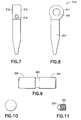
- FIG. 7 is a front elevational view of the carriage of the hinge assembly.
- FIG. 8 is a side elevational view of the carriage.
- FIG. 10 is a side elevational view of the hinge pin.
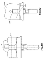
- FIG. 12 is a rear elevational view of the femoral component.
- FIG. 14 is a front elevational view of the hinge bearing.
- FIG. 15 is a side elevational view of the hinge pin bearing.
- FIG. 17 is a cross-sectional view similar to FIG. 16, but showing movement required for dislocation of the assembled bearing and carriage.
- FIG. 18 is a cross-sectional view similar to FIGS. 16 and 17, but showing the movement required for dislocation of the carriage relative to the assembled tibial component and bearing.
- FIG. 19 is a rear elevational view of the assembled knee prosthesis.
- FIG. 20 is a front elevational view thereof.
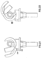
- FIG. 21 is a side elevational view of the assembled prosthesis showing the knee in a 5° hyperextension.
- FIG. 23 is a top plan view showing relative positions of the patella and femoral component during flexion.
- a hinged knee prosthesis in accordance with the invention is identified generally by the numeral 100 in FIGS. 1 and 19-23.
- the knee prosthesis 100 includes a femoral component identified generally by the numeral 200 in FIG. 1.
- the femoral component 200 is configured for mounting to the resected distal end of the natural femur 600.
- the femoral component 200 is configured for articulation relative to an assembly that includes a hinge subassembly 300, a plastic bearing 400 and a tibial component 500.
- the tibial component 500 is configured for mounting in the resected proximal end of the natural tibia 700.
- the prosthesis 100 may further include a patellar component 800 that may be implanted in the natural patella 900.
- the tibial component 500 includes a body 501 and a stabilizing rod 502 as shown in FIG. 1. Both the body 501 and the stabilizing rod 502 are formed from a metallic material that will provide appropriate strength and biocompatibility.
- a preferred tibial component 500 is made from a titanium alloy with a TiN coating. However, the tibial component 500 may also be formed from a CoCr alloy. Other metallic materials appropriate for use in the manufacture of the tibial component 500 will be known to those skilled in the art.
- the body 501 of the tibial component 500 is illustrated most clearly in FIGS. 2 and 3.
- the body 501 includes a conical hole 503 that extends distally from a superior tibial surface 504, and that tapers to smaller dimensions at locations further from the superior tibial surface 504.
- the conical hole 503 communicates with a cavity 505 that receives the proximal end of the stabilizing rod 502.
- a tibial plate 506 extends transverse to the axis defined by the conical hole 503 and includes the superior tibial surface 504.
- the inferior face of the tibial plate 506 is mountable on the resected proximal end of the natural tibia 700 as shown in FIG. 1.
- portions of the tibial component 500 below the tibial plate 506 are implanted into a cavity prepared in the resected proximal end of the tibia 700.
- the tibial component 500 may be used with a bone cement to achieve secure anchoring of the tibial component 500 in the tibia 700.
- external surface regions of the body 501 near the plate 506 may have a bone ingrowth surface region that will encourage growth of the natural bone for secure anchoring of the tibial component 500.
- the body 501 of the tibial component further includes an annular groove 507 formed near the distal end of the conical hole 503. Additionally, the tibial component 500 includes a stop pin 508 mounted to an anterior portion of the tibial plate 506. As explained further herein, the stop pin 508 cooperates with the bearing 400 to limit relative rotation between the bearing 400 and the tibial component 500.
- the bearing preferably is formed unitarily from a non-metallic material and most preferably from UHMWPe.
- the plastic of the bearing performs well under loads, exhibits good biocompatibility and does not interact with the metallic materials of the prosthesis 100 that are adjacent the bearing 400.
- the bearing 400 includes superior condylar bearing surfaces 401 at medial and lateral positions on the bearing 400.
- a hole 402 extends in a proximal to distal direction through the bearing 400. As shown most clearly in FIG. 6, the hole 402 includes a generally cylindrical proximal portion and a conically generated distal portion. Proximal portions of the hole 402 extend through a portion of the bearing 400 that is formed with opposite substantially planar side surfaces 403.
- a cone 407 extends distally from the inferior bearing surface 406 and has an outer surface configured for substantially congruent engagement in the conical hole 503 of the tibial component 500.
- the bearing 400 can rotate relative to the tibial component about the central axis of the conical hole 503 in the tibial component 500. This rotation will cause the inferior bearing surface 406 of the bearing 400 to rotate in engagement with the superior tibial surface 504.
- An anterior and superior position of the bearing 400 includes stop surfaces 408 that limit rotation of the femoral component 200 relative to the bearing in a hyperextension direction, as explained below.
- An annular groove 409 is formed in the cone 407 of the bearing 400 near the distal end of the cone 407.
- the groove 409 is disposed to align with the groove 507 of the tibial component 500.
- a snap ring then can be engaged simultaneously in the groove 409 and 507 to retain the cone 407 of the bearing in the conical hole 503 in the tibial component 500. This engagement will permit rotation of the bearing 400 relative to the tibial component 500, but will prevent dislocation of the bearing 400 from the tibial component 500.
- the bearing 400 further includes an arcuate slot 410 formed in an anterior portion of the inferior bearing surface 406.
- the slot 410 is configured to engage the stop pin 508 of the tibial component 500 and extends through an arc of preferably about 30°.
- the engagement of the stop pin 508 in the slot 410 limits the range of rotational motion of the bearing 400 relative to the tibial component.
- the size of the slot 508 and hence the range of rotational movement of the bearing 400 relative to the tibial component 500 will be selected in accordance with the mobility of the patient.
- the slot 410 can be replaced by a cylindrical opening to prevent all rotation between the bearing 400 and the tibial component 500.
- the hinge subassembly 300 includes a metal carriage 310 formed unitarily from a sufficiently strong biocompatible material, such as the material used to form the body 501 of the tibial component 500.
- the metal carriage 310 includes a head 311 with opposite planar highly polished surfaces 312.
- a shaft 313 extends distally from the head 311.
- the shaft 313 of the preferred embodiment includes a substantially cylindrical proximal portion and a conically tapered distal portion.
- the shaft 313 of the carriage 310 is configured for rotational engagement in the hole 402 of the bearing 400.
- a threaded hole 314 extends through the head 311 from an outer surface region substantially adjacent the shaft 313 to a pin support hole 315 formed in the head 311.
- the hinge subassembly 300 further includes a hinge pin 320 configured for engagement in the pin support hole 315.
- the hinge pin 320 include cylindrical bearing surfaces 321 adjacent opposite longitudinal ends and an engagement groove 322 between the cylindrical bearing surfaces 321..
- the femoral component 200 is formed from a metallic material that exhibits sufficient strength and biocompatibility.
- the femoral component 200 may be formed from the same material described above for the tibial component 500.
- the femoral component includes a femoral body 201 with a superior surface and a stabilizing rod 202 that extends proximally from the superior surface of the femoral body 201.
- the femoral body 201 can be mounted to the resected distal end of the natural femur 600 so that the stabilizing rod 202 can be mounted in a cavity prepared in the resected proximal end of the femur 600.
- the femoral component 200 can be affixed in the femur by bone cement or by natural bone ingrowth that may be promoted by an appropriate external surface configuration on portions of the femoral component 200.
- Inferior regions of the femoral body 201 define tibiofemoral articular surfaces 203 that are configured for congruent articular bearing engagement with the condylar bearing surfaces 401 of the bearing 400. More particularly, the tibiofemoral articular surfaces 203 are configured for congruent bearing articular engagement with the condylar bearing surface 401 of the bearing through a broad range of flexion extending at least from full extension to most ranges of flexion that are likely to be generated during high load conditions, such as stair climbing or standing from a sitting position. In a preferred embodiment, congruency will exist from approximately 5° hyperextension to approximately 150° flexion. This congruency results in reduced stress as compared to a line contact or point contact that might be achieved with non-congruent articulating surfaces. As a result, the load is distributed over a wider area and failure during high load activities is much less likely.
- Superior regions of the femoral body 201 include spaced apart hinge support walls 204 that are distanced from one another appropriate amounts for receiving the outer side surfaces 312 of the head 311.
- the superior face of the femoral body 201 also includes a rod support 205 that is engagement with the stabilizing rod 202 of the femoral component 200.
- Holes 206 extend through the hinge supports 204 and substantially align with one another.
- Plastic bushings 210 are engageable in the holes 206 and define internal diameters appropriate for rotatably bearing engaging the hinge pin 320.
- the prosthesis 100 is implanted by assembling an appropriate femoral stabilizing rod 202 to the femoral body 201 as described for example, in U.S. Patent No. 5,074,879.
- the plastic bushings 210 also are mounted in the holes 206 of the femoral body 201.
- the thrust flanges 211 of the plastic bushings 210 limit the insertion of the plastic bushings 210 into the holes 206.
- the substantially cylindrical hinge bearing surfaces 212 are located centrally in the holes 206. This subassembly of the femoral body 201, the femoral stabilizing rod 202 and the plastic bushings 210 define the femoral component 200.
- the bearing 400 then is assembled with the carriage 310 of the hinge subassembly 300. More particularly, the shaft 313 of the carriage 310 is inserted into the hole 402 of the bearing 400. The snap ring 409 engages in the groove 507 to prevent unintended separation of the carriage 310 from the bearing 400.
- the pin support hole 315 of the carriage 310 then is aligned with the hinge bearing surface 212 in the bushing 210 of the femoral component 200.
- the hinge pin 320 then is passed into a first hinge bearing surface 212, through the support hole 315 of the carriage 310 and into the second hinge bearing surface 212.
- the set screw 330 then is introduced into the threaded hole 314.
- the conical end 331 thereof engages in the groove 322 in the hinge pin 320, thereby clamping the pin 320 in place. This clamping is important to avoid metal-to-metal micro-motion that could generate harmful metallic wear debris.
- the tibial body 501 and the tibial stabilizing rod 502 then are assembled to form the component 500.
- the tibia and the femur are prepared in a known manner, including forming channels to receive the stabilizing rods 202 and 502 respectively.
- a box-like cavity is prepared in the central, distal and posterior aspect of the femur. The cavity is dimensioned to define an envelope surrounding the two support walls 204.
- the tibial component 500 then is implanted into the tibia and the femoral component 200 and hinge subassembly 300 are implanted in the femur 600.
- the joint then is distracted and the tapered end of the cone 407 of the bearing 400 is inserted into the conical hole 503 of the tibial body 501.
- the joint then is closed so that the implanted prosthesis 100 is in the disposition shown in FIGS. 1 and 19-23.
- the assembled prosthesis permits rotation about the axis A and the axis B in FIG. 19.
- the prosthesis 100 provides several advantages. First, the prosthesis 100 provides the valgus-varus stability with full congruency through the complete anticipated range of tibiofemoral articulation. Additionally, the superior patellofemoral articulation still maintains patellar tilt at low to moderate flexion angles. A patient who requires a hinged prosthetic joint is likely to have collateral ligaments that are deficient or absent. Hence, the remaining natural components of the knee joint may not be sufficient to resist dislocation. However, the snap ring or other such retention mechanism between the bearing 400 and the tibial component 500 prevents the relatively small amount of distraction shown in FIG. 17 that could lead to dislocation. Rather, the much larger distraction shown in FIG. 18 would be required to achieve by completely separating the much longer shaft 313 of the carriage 310 from the bearing 400. Accordingly, the knee prosthesis 100 provides very good dislocation resistance with a relatively short cone on the tibial component 500.
Abstract
Description
- The invention relates to a knee joint prosthesis, and particularly a hinged knee joint prosthesis.
- A natural knee joint includes the distal end of the femur with articular cartilage, the proximal end of the tibia with articular cartilage and a meniscus between the femur and tibia. The femur and the tibia are held in a proper relationship to the meniscus by ligaments. These stabilizing ligaments include the posterior cruciate ligament, the anterior cruciate ligament and collateral ligaments.
- The condyles at the distal end of the femur define compound curves. Hence, the degree of congruency between the condyles of the natural femur and the superior surface of the meniscus varies at different degrees of flexion. Flexion of the knee causes the tibia to rotate relative to the femur about an axis that extends generally in a medial-to-lateral direction. The non-congruent shapes of the femoral condyles and the superior face of the bearing causes the contact area of the femur to roll back relative to the tibia during certain ranges of flexion. Flexion also generates rotation of the tibia about its own axis. The amount of rotation of the tibia during flexion of the knee is controlled and limited by the ligaments.
- The natural knee joint can become damaged or diseased. For example, damage or disease to the knee can deteriorate the articular surfaces of the femur or tibia and can damage the articular cartilage between the bones. The prior art includes prosthetic knee joints to replace a damaged or diseased natural knee. A prosthetic knee joint typically includes a femoral component that is mounted to the distal end of a resected femur, a tibial component mounted to the proximal end of a resected tibia and a bearing between the femoral and tibial components. The inferior face of the femoral component of a prosthetic knee joint typically defines a pair of arcuate convex condyles. The superior face of the bearing has regions for articular bearing engagement with the condyles of the femoral component. The superior face of the tibial component may be substantially planar and is engaged with the inferior face of the bearing.
- Prior art prosthetic knee joints have taken many different forms, depending upon the preferences of the orthopedic surgeon, the condition of the natural knee and the health, age and mobility of the patient. Some prior art knee joint prostheses fixedly secure the inferior surface of the bearing to the superior surface of the tibial component. Other prior art knee joint prostheses provide somewhat greater mobility and permit rotational movement between the bearing and the tibial component. Still other prior art knee joint prostheses allow even greater mobility and permit a controlled amount of anterior-posterior sliding movement between the bearing and the tibial component in addition to the rotational movement.
- Prior art prosthetic knee joints for patients with viable ligaments and good stability have no hinges and rely upon retained ligaments to hold the femoral component in an acceptable range of positions relative to the bearing and the tibial component. However, patients without viable collateral ligaments require a knee joint prosthesis where the femoral component is hinged to substantially prevent both anterior-posterior movement of the femoral component relative to the tibial component and to prevent medial-lateral movement.
- U.S. Patent No. 5,824,096 issued to the inventors herein and discloses a hinged knee prosthesis where the condyles of the femoral component are defined by compound curves. Hence, congruency will exist for certain ranges of flexion, but a non-congruent line contact will exist between the femoral component and the bearing during other ranges of flexion. More particularly the femoral component of the prosthesis shown in U.S. Patent No. 5,824,096 is configured to provide a substantially congruent bearing in the critical peak loading phase of the normal walking cycle. However, a reduced posterior femoral radii of the condyles produces a more normal knee motion during flexion with an adequate line contact in deeper flexion phases of non-critical activity. The hinged knee prosthesis of U.S. Patent No. 5,824,096 also permits a controlled range of movement of the bearing relative to the tibial and femoral components along an anterior-posterior axis. Additionally, the hinged connection disclosed in U.S. Patent No. 5,824,096 permits a controlled movement of the femoral component away from the tibial component. The compound curves of the femoral component combined with the ability of the bearing to move in anterior and posterior directions causes the femoral component to climb and roll back on the bearing during certain ranges of flexion. The hinge of the prosthesis shown in U.S. Patent No. 5,824,096 is used primarily for stabilization and performs only a minimal load bearing function. Thus, the hinge can be much smaller than knee prostheses where the hinge performs a primary load bearing function. The smaller hinge minimizes bone removal and hence helps to achieve an improved implant fixation. The smaller hinge also is lighter, and hence minimizes the effect of prosthesis weight on the gait of the patient.
- The hinged knee prosthesis of U.S. Patent No. 5,824,096 has performed very well since its first introduction and use. However, wear could be reduced further if femoral congruency existed for a greater range of knee motion, rather than only during peak loading phases during walking. For example, congruent contact during many high load activities, such as stair climbing and decent, arising from a chair and other moderate to deep flexion activities would be helpful for improving wear of the prosthesis. Additionally, a prosthesis with a tibial component that extended a smaller distance into the tibia would require less bone removal for implantation, and hence would be received well.
- The invention relates to a hinged knee prosthesis with a condylar bearing. The prosthesis includes a femoral component for mounting to the resected distal end of the femur, a tibial component for mounting to the resected proximal end of the tibia, a bearing for disposition between the femoral and tibial components and a hinge assembly for providing stability during articulation between the femoral and tibial components. The prosthesis may further include a patellar component.
- The hinged knee prosthesis of the subject invention differs from prior art hinged knee prostheses by providing patellofemoral articulating surfaces that are distinct from the tibiofemoral articulating surfaces. The patellofemoral articulation may be similar or identical to that of prior art knee prostheses and may include a compound curve as the articulating surface on the femoral component. However, the tibiofemoral articulating surface is configured for congruent contact over a larger range of motion than is available for knee prosthesis without distinct tibiofemoral and patellofemoral articulating surface. Preferably the congruent contact for the tibiofemoral articulation extends for substantially the entire range of motion. This provides a significant advantage of reduced wear, as compared to prior art prosthetic knees, including prior art hinged knee prostheses.
- Prosthetic knees with distinct patellofemoral and tibiofemoral articulating surfaces have been contemplated in non-hinged prosthetic knee designs. However, such a design would not accommodate valgus-varus motion, which is motion in a generally medial to lateral direction. However, a hinged knee provides adequate resistance to valgus-varus motion, and hence is well suited to distinct patellofemoral and tibiofemoral surfaces.
- The tibial component of the prosthetic knee includes an axial support, such as a stabilizing rod that can be mounted in a prepared cavity in the resected proximal end of the tibia. The tibial component further includes a tibial plate that extends transverse to the axial support and that can be mounted on the resected proximal end of the tibia. The tibial plate includes a superior tibial surface that may be substantially planar. The tibial component further includes a conical hole extending through the tibial plate and towards the axial support and stabilization rod. A groove may be formed near the distal end of the conical hole.
- The bearing of the prosthetic knee includes a plastic cone that can be mounted in the conical hole of the tibial component so that the bearing can rotate relative to the tibial component. The cone of the bearing preferably includes axial separation means for preventing axial separation or dislocation of the bearing from the tibial component. Thus, the prosthetic knee can provide dislocation resistance at least as good as prior art hinged prostheses, but with a shorter cone and hence less bone removal. The axial separation means may include a groove in the cone of the bearing that will align with the groove in the conical hole of the tibial component when the cone of the bearing is mounted in the conical hole of the tibial component. A snap ring may be engageable in the aligned grooves of the conical hole in the tibial component and in the cone of the bearing. The snap ring prevents the bearing from moving proximally and out of the conical hole in the tibial component. However, the snap ring permits the cone of the bearing to rotate relative to the tibial component. Hence, rotational mobility for the bearing is permitted, but dislocation of the bearing is prevented. Other connections that permit rotation but not separation can be provided
- The bearing further includes an inferior bearing surface for bearing engagement on the superior tibial surface of the tibial component. Means may be provided for limiting rotational movement of the bearing on the superior tibial surface. For example, the inferior surface of the bearing may be formed with an arcuate groove, and a pin may project from the superior surface of the tibial component for engagement in the groove of the bearing. Thus, the angular extend of the groove in the bearing will limit the range of pivotal movement of the bearing relative to the tibial component. The bearing further includes a superior condylar bearing region for articular bearing engagement with the femoral component. The bearing further include a hole extending from the proximal or superior end to or towards the distal end. Lower portions of the hole in the bearing may be conically tapered.
- The hinge assembly includes a carriage with a shaft configured for insertion into the hole of the bearing. The carriage further includes a head with smoothly polished side surfaces that may be substantially parallel to one another. A hinge support hole extends through the head and transverse to the axis of the shaft. The hinge assembly further includes a hinge pin that can be inserted into the pin support hole in the head of the carriage and a set screw for mounting in a threaded hole in the head to hold the hinge pin in position in the head.
- The femoral component includes a superior surface configured for mounting on the resected distal end of the femur. A stabilizing rod may project from the superior surface for mounting in a cavity prepared in the resected distal end of the femur. The femoral component further include hinge support walls that project proximally from the superior surface of the femoral component. The walls are substantially parallel to one another and are spaced apart sufficiently for receiving the head of the carriage. The hinge support walls further include holes that align with one another for receiving opposite ends of the hinge pin. The inferior region of the femoral component include a tibiofemoral articular surface and a distinct patellofemoral articulating surface. The patellofemoral articulating surface may define a curved shape similar to the shape of the articular surface on the femoral component disclosed in the above-referenced U.S. Patent No. 5,824,096. The tibiofemoral articulating surface is configured for congruent articular bearing engagement with the condylar bearing region of the bearing.
- The congruent articular bearing engagement of the tibiofemoral articular surface of the femoral component with the condylar bearing region on the superior surface of the bearing provides congruency through virtually all ranges of motion from a slightly hyperextended condition to deep flexion. Thus, the prosthetic knee of the subject invention provides congruent contact during many high load activities, such as stair climbing and descent and arising from a chair. Additionally, the prosthetic knee of the subject invention provides very good resistance to valgus-varus moments. Furthermore, the engagement of the cone of the bearing in the conical hole of the tibial component resists dislocation and the engagement of the stop pin with the groove in the inferior bearing surface of the bearing controls and limits the range of permissible rotation of the tibia relative to the femur. Thus, the prosthetic knee of the subject invention is well suited for those situations where the ligaments are not present or are ineffective.
- FIG. 1 is a longitudinal cross-sectional view of the assembled and implanted hinged knee prosthesis of the subject invention.
- FIG. 2 is a top plan view of the tibial component.
- FIG. 3 is a cross-sectional view taken along line 3-3 in FIG. 2.
- FIG. 4 is a side elevational view of the bearing.
- FIG. 5 is a top plan view of the bearing.
- FIG. 6 is a cross-sectional view taken along line 6-6 in FIG. 5.
- FIG. 7 is a front elevational view of the carriage of the hinge assembly.
- FIG. 8 is a side elevational view of the carriage.
- FIG. 9 is a front elevational view of the hinge pin of the hinge assembly.
- FIG. 10 is a side elevational view of the hinge pin.
- FIG. 11 is a side elevational view of the set screw.
- FIG. 12 is a rear elevational view of the femoral component.
- FIG. 13 is a side elevational view of the femoral component.
- FIG. 14 is a front elevational view of the hinge bearing.
- FIG. 15 is a side elevational view of the hinge pin bearing.
- FIG. 16 is a longitudinal cross-sectional view of the tibial component, bearing and carriage in their assembled condition.
- FIG. 17 is a cross-sectional view similar to FIG. 16, but showing movement required for dislocation of the assembled bearing and carriage.
- FIG. 18 is a cross-sectional view similar to FIGS. 16 and 17, but showing the movement required for dislocation of the carriage relative to the assembled tibial component and bearing.
- FIG. 19 is a rear elevational view of the assembled knee prosthesis.
- FIG. 20 is a front elevational view thereof.
- FIG. 21 is a side elevational view of the assembled prosthesis showing the knee in a 5° hyperextension.
- FIG. 22 is a cross-sectional view showing the assembled knee at approximately 150° flexion, and showing the set screw in an exploded orientation.
- FIG. 23 is a top plan view showing relative positions of the patella and femoral component during flexion.
- A hinged knee prosthesis in accordance with the invention is identified generally by the numeral 100 in FIGS. 1 and 19-23. The
knee prosthesis 100 includes a femoral component identified generally by the numeral 200 in FIG. 1. Thefemoral component 200 is configured for mounting to the resected distal end of thenatural femur 600. Thefemoral component 200 is configured for articulation relative to an assembly that includes ahinge subassembly 300, aplastic bearing 400 and atibial component 500. Thetibial component 500 is configured for mounting in the resected proximal end of thenatural tibia 700. Theprosthesis 100 may further include apatellar component 800 that may be implanted in thenatural patella 900. - The
tibial component 500 includes abody 501 and a stabilizingrod 502 as shown in FIG. 1. Both thebody 501 and the stabilizingrod 502 are formed from a metallic material that will provide appropriate strength and biocompatibility. Apreferred tibial component 500 is made from a titanium alloy with a TiN coating. However, thetibial component 500 may also be formed from a CoCr alloy. Other metallic materials appropriate for use in the manufacture of thetibial component 500 will be known to those skilled in the art. - The
body 501 of thetibial component 500 is illustrated most clearly in FIGS. 2 and 3. Thebody 501 includes aconical hole 503 that extends distally from asuperior tibial surface 504, and that tapers to smaller dimensions at locations further from thesuperior tibial surface 504. Theconical hole 503 communicates with acavity 505 that receives the proximal end of the stabilizingrod 502. - A
tibial plate 506 extends transverse to the axis defined by theconical hole 503 and includes thesuperior tibial surface 504. The inferior face of thetibial plate 506 is mountable on the resected proximal end of thenatural tibia 700 as shown in FIG. 1. Additionally, portions of thetibial component 500 below thetibial plate 506 are implanted into a cavity prepared in the resected proximal end of thetibia 700. Thetibial component 500 may be used with a bone cement to achieve secure anchoring of thetibial component 500 in thetibia 700. Alternatively, external surface regions of thebody 501 near theplate 506 may have a bone ingrowth surface region that will encourage growth of the natural bone for secure anchoring of thetibial component 500. - The
body 501 of the tibial component further includes anannular groove 507 formed near the distal end of theconical hole 503. Additionally, thetibial component 500 includes astop pin 508 mounted to an anterior portion of thetibial plate 506. As explained further herein, thestop pin 508 cooperates with the bearing 400 to limit relative rotation between the bearing 400 and thetibial component 500. - The bearing preferably is formed unitarily from a non-metallic material and most preferably from UHMWPe. The plastic of the bearing performs well under loads, exhibits good biocompatibility and does not interact with the metallic materials of the
prosthesis 100 that are adjacent thebearing 400. Thebearing 400 includes superior condylar bearing surfaces 401 at medial and lateral positions on thebearing 400. Ahole 402 extends in a proximal to distal direction through thebearing 400. As shown most clearly in FIG. 6, thehole 402 includes a generally cylindrical proximal portion and a conically generated distal portion. Proximal portions of thehole 402 extend through a portion of thebearing 400 that is formed with opposite substantially planar side surfaces 403. The side surfaces 403 extend generally in anterior-to-posterior directions and are approximately parallel to one another. The bearing further includes aninferior bearing surface 406 configured for congruent bearing engagement with thesuperior tibial surface 504. In the illustrated embodiment, both thesuperior tibial surface 504 and theinferior bearing surface 406 of theplastic bearing 400 are substantially planar. - A
cone 407 extends distally from theinferior bearing surface 406 and has an outer surface configured for substantially congruent engagement in theconical hole 503 of thetibial component 500. Thus, the bearing 400 can rotate relative to the tibial component about the central axis of theconical hole 503 in thetibial component 500. This rotation will cause theinferior bearing surface 406 of thebearing 400 to rotate in engagement with thesuperior tibial surface 504. An anterior and superior position of thebearing 400 includes stop surfaces 408 that limit rotation of thefemoral component 200 relative to the bearing in a hyperextension direction, as explained below. Anannular groove 409 is formed in thecone 407 of thebearing 400 near the distal end of thecone 407. Thegroove 409 is disposed to align with thegroove 507 of thetibial component 500. A snap ring then can be engaged simultaneously in thegroove cone 407 of the bearing in theconical hole 503 in thetibial component 500. This engagement will permit rotation of thebearing 400 relative to thetibial component 500, but will prevent dislocation of the bearing 400 from thetibial component 500. - The bearing 400 further includes an
arcuate slot 410 formed in an anterior portion of theinferior bearing surface 406. Theslot 410 is configured to engage thestop pin 508 of thetibial component 500 and extends through an arc of preferably about 30°. The engagement of thestop pin 508 in theslot 410 limits the range of rotational motion of thebearing 400 relative to the tibial component. The size of theslot 508 and hence the range of rotational movement of thebearing 400 relative to thetibial component 500 will be selected in accordance with the mobility of the patient. In some instances, theslot 410 can be replaced by a cylindrical opening to prevent all rotation between the bearing 400 and thetibial component 500. - The
hinge subassembly 300 includes ametal carriage 310 formed unitarily from a sufficiently strong biocompatible material, such as the material used to form thebody 501 of thetibial component 500. Themetal carriage 310 includes ahead 311 with opposite planar highlypolished surfaces 312. Ashaft 313 extends distally from thehead 311. Theshaft 313 of the preferred embodiment includes a substantially cylindrical proximal portion and a conically tapered distal portion. Theshaft 313 of thecarriage 310 is configured for rotational engagement in thehole 402 of thebearing 400. A threadedhole 314 extends through thehead 311 from an outer surface region substantially adjacent theshaft 313 to apin support hole 315 formed in thehead 311. - The
hinge subassembly 300 further includes ahinge pin 320 configured for engagement in thepin support hole 315. Thehinge pin 320 include cylindrical bearing surfaces 321 adjacent opposite longitudinal ends and anengagement groove 322 between the cylindrical bearing surfaces 321.. - The
hinge subassembly 300 further includes aset screw 330 with a conicalleading end 331. Theset screw 330 can be threadedly engaged in the threadedhole 314 of thecarriage 310 so that theleading end 331 of theset screw 330 engages in thegroove 322 of thehinge pin 320. Thus, thehinge pin 320 can be retained fixedly in thepin support hole 315 of thecarriage 310. - The
femoral component 200 is formed from a metallic material that exhibits sufficient strength and biocompatibility. For example, thefemoral component 200 may be formed from the same material described above for thetibial component 500. The femoral component includes afemoral body 201 with a superior surface and a stabilizingrod 202 that extends proximally from the superior surface of thefemoral body 201. Thefemoral body 201 can be mounted to the resected distal end of thenatural femur 600 so that the stabilizingrod 202 can be mounted in a cavity prepared in the resected proximal end of thefemur 600. Thefemoral component 200 can be affixed in the femur by bone cement or by natural bone ingrowth that may be promoted by an appropriate external surface configuration on portions of thefemoral component 200. - Inferior regions of the
femoral body 201 define tibiofemoralarticular surfaces 203 that are configured for congruent articular bearing engagement with the condylar bearing surfaces 401 of thebearing 400. More particularly, the tibiofemoralarticular surfaces 203 are configured for congruent bearing articular engagement with thecondylar bearing surface 401 of the bearing through a broad range of flexion extending at least from full extension to most ranges of flexion that are likely to be generated during high load conditions, such as stair climbing or standing from a sitting position. In a preferred embodiment, congruency will exist from approximately 5° hyperextension to approximately 150° flexion. This congruency results in reduced stress as compared to a line contact or point contact that might be achieved with non-congruent articulating surfaces. As a result, the load is distributed over a wider area and failure during high load activities is much less likely. - Superior regions of the
femoral body 201 include spaced apart hingesupport walls 204 that are distanced from one another appropriate amounts for receiving the outer side surfaces 312 of thehead 311. The superior face of thefemoral body 201 also includes arod support 205 that is engagement with the stabilizingrod 202 of thefemoral component 200. -
Holes 206 extend through the hinge supports 204 and substantially align with one another.Plastic bushings 210 are engageable in theholes 206 and define internal diameters appropriate for rotatably bearing engaging thehinge pin 320. - The
femoral body 201 includes a patellofemoral articulatingsurface 207 with asuperior region 208 and an inferior region 309 as shown in FIGS. 13 and 20. Thesuperior region 208 of the patellofemoral articulatingsurface 207 is wider than theinferior region 209 since at lower flexion angles thepatella 900 is in a relatively superior position, and may be displaced medially, as shown in FIG. 23. At moderate to large flexion, thepatella 900 is central and the inferiorpatellofemoral articulating surface 209 need not be wider than thepatella 900. - The
prosthesis 100 is implanted by assembling an appropriatefemoral stabilizing rod 202 to thefemoral body 201 as described for example, in U.S. Patent No. 5,074,879. Theplastic bushings 210 also are mounted in theholes 206 of thefemoral body 201. As a result, thethrust flanges 211 of theplastic bushings 210 limit the insertion of theplastic bushings 210 into theholes 206. Additionally, the substantially cylindricalhinge bearing surfaces 212 are located centrally in theholes 206. This subassembly of thefemoral body 201, thefemoral stabilizing rod 202 and theplastic bushings 210 define thefemoral component 200. - The bearing 400 then is assembled with the
carriage 310 of thehinge subassembly 300. More particularly, theshaft 313 of thecarriage 310 is inserted into thehole 402 of thebearing 400. Thesnap ring 409 engages in thegroove 507 to prevent unintended separation of thecarriage 310 from thebearing 400. Thepin support hole 315 of thecarriage 310 then is aligned with thehinge bearing surface 212 in thebushing 210 of thefemoral component 200. Thehinge pin 320 then is passed into a firsthinge bearing surface 212, through thesupport hole 315 of thecarriage 310 and into the secondhinge bearing surface 212. Theset screw 330 then is introduced into the threadedhole 314. As theset screw 330 is tightened, theconical end 331 thereof engages in thegroove 322 in thehinge pin 320, thereby clamping thepin 320 in place. This clamping is important to avoid metal-to-metal micro-motion that could generate harmful metallic wear debris. Thetibial body 501 and thetibial stabilizing rod 502 then are assembled to form thecomponent 500. - The tibia and the femur are prepared in a known manner, including forming channels to receive the stabilizing
rods support walls 204. Thetibial component 500 then is implanted into the tibia and thefemoral component 200 and hinge subassembly 300 are implanted in thefemur 600. The joint then is distracted and the tapered end of thecone 407 of thebearing 400 is inserted into theconical hole 503 of thetibial body 501. The joint then is closed so that the implantedprosthesis 100 is in the disposition shown in FIGS. 1 and 19-23. The assembled prosthesis permits rotation about the axis A and the axis B in FIG. 19. - The
prosthesis 100 provides several advantages. First, theprosthesis 100 provides the valgus-varus stability with full congruency through the complete anticipated range of tibiofemoral articulation. Additionally, the superior patellofemoral articulation still maintains patellar tilt at low to moderate flexion angles. A patient who requires a hinged prosthetic joint is likely to have collateral ligaments that are deficient or absent. Hence, the remaining natural components of the knee joint may not be sufficient to resist dislocation. However, the snap ring or other such retention mechanism between the bearing 400 and thetibial component 500 prevents the relatively small amount of distraction shown in FIG. 17 that could lead to dislocation. Rather, the much larger distraction shown in FIG. 18 would be required to achieve by completely separating the muchlonger shaft 313 of thecarriage 310 from thebearing 400. Accordingly, theknee prosthesis 100 provides very good dislocation resistance with a relatively short cone on thetibial component 500. - While the invention has been described with respect to certain embodiments, it is apparent that various changes can be made without departing from the scope of the invention as defined by the appended claims.
Claims (10)
- A hinged knee prosthesis comprising:a tibial component having an inferior surface for mounting to a tibia and a superior bearing surface;a bearing having an inferior bearing surface supported on the tibial component and a superior condylar bearing surface;a hinge carriage having a shaft mounted in the bearing and a head; anda femoral component having a superior surface for mounting to a femur, an inferior tibiofemoral articular surface configured relative to the condylar bearing surface for achieving congruent tibiofemoral articulation, the femoral component further having a patellofemoral articulating surface distinct from the tibiofemoral articular surface for permitting patellar tilt at low to moderate flexion angles.
- The prosthesis of claim 1, wherein the tibiofemoral articular surface of the femoral component is configured relative to the condylar bearing surface of the bearing to achieve fully congruent tibiofemoral articulation at least through a range from full extension to at least 90° flexion.
- The prosthesis of claim 1 or 2, wherein fully congruent tibiofemoral articulation is achieved to approximately 150° flexion.
- The prosthesis of any of claims 1 to 3, wherein the patellofemoral articulating surface includes a superior region and an inferior region, the superior region of the patellofemoral articulating surface being wider than the inferior region thereof to permit medial displacement of the patella at low flexion angles, while maintaining a substantially centralized disposition of the patella at larger flexion angles.
- The prosthesis of any of claims 1 to 4, further including a stop surface on the femoral component and a stop surface on the bearing that engage and limit hyperextension of the prosthesis.
- The prosthesis of any of claims 1 to 5, wherein the tibial component includes a conical hole extending into a superior surface thereof, the bearing including a cone pivotally engaged in the conical hole of the tibial component for rotation about central axes of the cone and the conical hole.
- The prosthesis of claim 6, further comprising engagement means between the cone of the bearing and the conical hole of the tibial component for preventing axial separation and thereby resisting dislocation of the prosthesis.
- The prosthesis of claim 6 or 7, wherein the engagement means includes an annular groove formed in the conical hole of the tibial component and a projection formed on the cone of the bearing.
- The prosthesis of any of claims 6 to 8, wherein the cone of the bearing includes an annular groove and the projection is a snap ring engaged in the annular grooves of the cone of the bearing and the conical hole of the tibial component.
- The prosthesis of any of claims 1 to 9, wherein the femoral component includes two spaced apart hinge support walls disposed respectively on opposite respective sides of the head of the carriage for resisting valgus-varus moments.
Applications Claiming Priority (2)
| Application Number | Priority Date | Filing Date | Title |
|---|---|---|---|
| US56621404P | 2004-04-28 | 2004-04-28 | |
| US566214P | 2004-04-28 |
Publications (2)
| Publication Number | Publication Date |
|---|---|
| EP1591083A1 true EP1591083A1 (en) | 2005-11-02 |
| EP1591083B1 EP1591083B1 (en) | 2007-09-05 |
Family
ID=34935916
Family Applications (1)
| Application Number | Title | Priority Date | Filing Date |
|---|---|---|---|
| EP05009381A Not-in-force EP1591083B1 (en) | 2004-04-28 | 2005-04-28 | Prosthetic knee |
Country Status (6)
| Country | Link |
|---|---|
| US (1) | US20050246028A1 (en) |
| EP (1) | EP1591083B1 (en) |
| JP (1) | JP4681931B2 (en) |
| AT (1) | ATE372097T1 (en) |
| AU (1) | AU2005201780B8 (en) |
| DE (1) | DE602005002293T2 (en) |
Cited By (1)
| Publication number | Priority date | Publication date | Assignee | Title |
|---|---|---|---|---|
| GB2433698B (en) * | 2005-12-28 | 2010-06-02 | Derek James Wallace Mcminn | Improvements in or relating to knee prosthesis |
Families Citing this family (28)
| Publication number | Priority date | Publication date | Assignee | Title |
|---|---|---|---|---|
| US6719800B2 (en) | 2001-01-29 | 2004-04-13 | Zimmer Technology, Inc. | Constrained prosthetic knee with rotating bearing |
| US6485519B2 (en) | 2001-01-29 | 2002-11-26 | Bristol-Myers Squibb Company | Constrained prosthetic knee with rotating bearing |
| AU2002364107B2 (en) | 2001-12-21 | 2008-09-25 | Smith & Nephew, Inc. | Hinged joint system |
| US7753959B2 (en) * | 2006-03-20 | 2010-07-13 | Biomet Manufacturing Corp. | Modular center pegged glenoid |
| US8425614B2 (en) * | 2006-03-20 | 2013-04-23 | Biomet Manufacturing Corp. | Modular center pegged glenoid |
| AU2007269203B2 (en) * | 2006-06-30 | 2014-03-06 | Smith & Nephew, Inc. | Anatomical motion hinged prosthesis |
| US8187280B2 (en) | 2007-10-10 | 2012-05-29 | Biomet Manufacturing Corp. | Knee joint prosthesis system and method for implantation |
| US8562616B2 (en) | 2007-10-10 | 2013-10-22 | Biomet Manufacturing, Llc | Knee joint prosthesis system and method for implantation |
| US8328873B2 (en) | 2007-01-10 | 2012-12-11 | Biomet Manufacturing Corp. | Knee joint prosthesis system and method for implantation |
| US8163028B2 (en) | 2007-01-10 | 2012-04-24 | Biomet Manufacturing Corp. | Knee joint prosthesis system and method for implantation |
| US8157869B2 (en) | 2007-01-10 | 2012-04-17 | Biomet Manufacturing Corp. | Knee joint prosthesis system and method for implantation |
| US7918893B2 (en) * | 2007-09-30 | 2011-04-05 | Depuy Products, Inc. | Hinged orthopaedic prosthesis |
| US7871442B2 (en) * | 2007-11-30 | 2011-01-18 | Howmedica Osteonics Corp. | Knee prosthesis with four degrees freedom |
| US20110035019A1 (en) * | 2009-07-09 | 2011-02-10 | Wright State University | Total ankle replacement system |
| EP2272466A1 (en) | 2009-07-10 | 2011-01-12 | Medizinische Hochschule Hannover | Knee joint prosthesis and method for producing said prosthesis |
| US8545571B2 (en) | 2010-07-30 | 2013-10-01 | Howmedica Osteonics Corp. | Stabilized knee prosthesis |
| US8506638B2 (en) | 2011-07-13 | 2013-08-13 | Biomets Manufacturing, LLC | Shoulder prosthesis |
| US20130018476A1 (en) | 2011-07-13 | 2013-01-17 | Biomet Manufacturing Corp. | Shoulder prosthesis |
| US10548735B2 (en) | 2015-08-06 | 2020-02-04 | Howmedica Osteonics Corp. | Modular hinge knee prosthesis and improvements of same |
| US10722372B2 (en) | 2016-07-05 | 2020-07-28 | Howmedica Osteonics Corp. | Hinge knee preparation instrumentation and associated methods |
| US10925743B2 (en) * | 2017-09-26 | 2021-02-23 | Stephen J. Incavo | Knee arthroplasty with modular femoral adapters |
| US10893948B2 (en) | 2017-11-02 | 2021-01-19 | Howmedica Osteonics Corp. | Rotary arc patella articulating geometry |
| US10736748B2 (en) | 2018-05-02 | 2020-08-11 | Depuy Ireland Unlimited Company | Orthopaedic prosthetic system for a hinged-knee prosthesis |
| US11607323B2 (en) | 2018-10-15 | 2023-03-21 | Howmedica Osteonics Corp. | Patellofemoral trial extractor |
| US11033396B2 (en) | 2019-02-05 | 2021-06-15 | Depuy Ireland Unlimited Company | Orthopaedic prosthetic system for a rotating hinged-knee prosthesis |
| AU2020200145A1 (en) * | 2019-02-05 | 2020-08-20 | Depuy Ireland Unlimited Company | Orthopaedic prosthetic system for a rotating hinged-knee prosthesis |
| US11116641B2 (en) | 2019-02-05 | 2021-09-14 | Depuy Ireland Unlimited Company | Orthopaedic prosthetic system for a rotating hinged-knee prosthesis |
| AU2021200854A1 (en) | 2020-03-03 | 2021-09-16 | Howmedica Osteonics Corp. | Glenoid implant with additively manufactured fixation posts |
Citations (5)
| Publication number | Priority date | Publication date | Assignee | Title |
|---|---|---|---|---|
| US5011496A (en) * | 1988-02-02 | 1991-04-30 | Joint Medical Products Corporation | Prosthetic joint |
| US5370701A (en) * | 1990-09-28 | 1994-12-06 | Arch Development Corporation | Rotating/sliding contrained prosthetic knee |
| US5824096A (en) * | 1994-12-12 | 1998-10-20 | Biomedical Engineering Trust I | Hinged knee prosthesis with condylar bearing |
| EP0904748A2 (en) * | 1997-09-25 | 1999-03-31 | Johnson & Johnson Professional, Inc. | Knee prosthesis with a rotatable tibial bearing having a keyed axial securement |
| US6264696B1 (en) * | 1999-01-04 | 2001-07-24 | Aesculap | Tibial knee prosthesis comprising a ball joint with double inserts |
Family Cites Families (16)
| Publication number | Priority date | Publication date | Assignee | Title |
|---|---|---|---|---|
| US4219893A (en) * | 1977-09-01 | 1980-09-02 | United States Surgical Corporation | Prosthetic knee joint |
| BR7506468A (en) * | 1975-10-03 | 1975-12-02 | S Eshriqui | ARTICULATED KNEE PROSTHESIS |
| US4206517A (en) * | 1977-12-01 | 1980-06-10 | Biomedical Engineering Corp. | Floating center prosthetic joint |
| DE2965891D1 (en) * | 1978-03-10 | 1983-08-25 | Biomedical Eng Corp | Improved joint endoprosthesis |
| US4470158A (en) * | 1978-03-10 | 1984-09-11 | Biomedical Engineering Corp. | Joint endoprosthesis |
| US4353135A (en) * | 1980-05-09 | 1982-10-12 | Minnesota Mining And Manufacturing Company | Patellar flange and femoral knee-joint prosthesis |
| US4888021A (en) * | 1988-02-02 | 1989-12-19 | Joint Medical Products Corporation | Knee and patellar prosthesis |
| US5139521A (en) * | 1990-01-27 | 1992-08-18 | Ingrid Schelhas | Knee prosthesis |
| US5314481A (en) * | 1992-11-12 | 1994-05-24 | Wright Medical Technology, Inc. | Hinged knee prosthesis with extended patellar track |
| US5951603A (en) * | 1997-09-25 | 1999-09-14 | Johnson & Johnson Professional, Inc. | Rotatable joint prosthesis with axial securement |
| US5782925A (en) * | 1997-11-06 | 1998-07-21 | Howmedica Inc. | Knee implant rotational alignment apparatus |
| DE69913048T2 (en) * | 1998-08-05 | 2004-09-16 | Biomedical Engineering Trust I | Knee joint prosthesis with prevention of luxation |
| US6152960A (en) * | 1998-10-13 | 2000-11-28 | Biomedical Engineering Trust I | Femoral component for knee endoprosthesis |
| US6368354B2 (en) * | 1999-10-07 | 2002-04-09 | Exactech, Inc. | Acetabular bearing assembly for total hip joints |
| FR2805455B1 (en) * | 2000-02-24 | 2002-04-19 | Aesculap Sa | FEMORAL COMPONENT OF A THREE-BEND KNEE PROSTHESIS |
| US6485519B2 (en) * | 2001-01-29 | 2002-11-26 | Bristol-Myers Squibb Company | Constrained prosthetic knee with rotating bearing |
-
2005
- 2005-04-27 JP JP2005130438A patent/JP4681931B2/en not_active Expired - Fee Related
- 2005-04-27 US US11/115,920 patent/US20050246028A1/en not_active Abandoned
- 2005-04-28 EP EP05009381A patent/EP1591083B1/en not_active Not-in-force
- 2005-04-28 DE DE602005002293T patent/DE602005002293T2/en active Active
- 2005-04-28 AU AU2005201780A patent/AU2005201780B8/en not_active Ceased
- 2005-04-28 AT AT05009381T patent/ATE372097T1/en not_active IP Right Cessation
Patent Citations (5)
| Publication number | Priority date | Publication date | Assignee | Title |
|---|---|---|---|---|
| US5011496A (en) * | 1988-02-02 | 1991-04-30 | Joint Medical Products Corporation | Prosthetic joint |
| US5370701A (en) * | 1990-09-28 | 1994-12-06 | Arch Development Corporation | Rotating/sliding contrained prosthetic knee |
| US5824096A (en) * | 1994-12-12 | 1998-10-20 | Biomedical Engineering Trust I | Hinged knee prosthesis with condylar bearing |
| EP0904748A2 (en) * | 1997-09-25 | 1999-03-31 | Johnson & Johnson Professional, Inc. | Knee prosthesis with a rotatable tibial bearing having a keyed axial securement |
| US6264696B1 (en) * | 1999-01-04 | 2001-07-24 | Aesculap | Tibial knee prosthesis comprising a ball joint with double inserts |
Cited By (2)
| Publication number | Priority date | Publication date | Assignee | Title |
|---|---|---|---|---|
| GB2433698B (en) * | 2005-12-28 | 2010-06-02 | Derek James Wallace Mcminn | Improvements in or relating to knee prosthesis |
| US7878989B2 (en) | 2005-12-28 | 2011-02-01 | Mcminn Derek James Wallace | Knee prostheses |
Also Published As
| Publication number | Publication date |
|---|---|
| JP4681931B2 (en) | 2011-05-11 |
| AU2005201780A1 (en) | 2005-11-17 |
| JP2005312973A (en) | 2005-11-10 |
| DE602005002293T2 (en) | 2008-05-29 |
| US20050246028A1 (en) | 2005-11-03 |
| AU2005201780B2 (en) | 2011-02-17 |
| AU2005201780A8 (en) | 2005-11-17 |
| DE602005002293D1 (en) | 2007-10-18 |
| ATE372097T1 (en) | 2007-09-15 |
| EP1591083B1 (en) | 2007-09-05 |
| AU2005201780B8 (en) | 2011-02-24 |
Similar Documents
| Publication | Publication Date | Title |
|---|---|---|
| EP1591083B1 (en) | Prosthetic knee | |
| US6413279B1 (en) | Floating bearing knee joint prosthesis with a fixed tibial post | |
| US6080195A (en) | Rotatable and translatable joint prosthesis with posterior stabilization | |
| US9642711B2 (en) | High flexion articular insert | |
| US6165223A (en) | Floating bearing knee joint prosthesis with a fixed tibial post | |
| US6238434B1 (en) | Knee joint prosthesis with spinout prevention | |
| US6972039B2 (en) | Floating bearing knee joint prosthesis with a fixed tibial post | |
| US7413577B1 (en) | Total stabilized knee prosthesis with constraint | |
| AU737463B2 (en) | Four compartment knee | |
| US6206926B1 (en) | Prosthetic knee joint with enhanced posterior stabilization and dislocation prevention features | |
| US8715358B2 (en) | PCL retaining ACL substituting TKA apparatus and method | |
| EP3127510B1 (en) | Modular hinge knee prosthesis | |
| AU2640901A (en) | Posterior stabilized prosthetic knee replacement with bearing translation and dislocation prevention features | |
| US8900315B2 (en) | Constrained condylar knee device | |
| EP0420460A1 (en) | Knee prosthesis | |
| AU2014200110A1 (en) | High flexion articular insert |
Legal Events
| Date | Code | Title | Description |
|---|---|---|---|
| PUAI | Public reference made under article 153(3) epc to a published international application that has entered the european phase |
Free format text: ORIGINAL CODE: 0009012 |
|
| AK | Designated contracting states |
Kind code of ref document: A1 Designated state(s): AT BE BG CH CY CZ DE DK EE ES FI FR GB GR HU IE IS IT LI LT LU MC NL PL PT RO SE SI SK TR |
|
| AX | Request for extension of the european patent |
Extension state: AL BA HR LV MK YU |
|
| 17P | Request for examination filed |
Effective date: 20060413 |
|
| AKX | Designation fees paid |
Designated state(s): AT BE BG CH CY CZ DE DK EE ES FI FR GB GR HU IE IS IT LI LT LU MC NL PL PT RO SE SI SK TR |
|
| GRAP | Despatch of communication of intention to grant a patent |
Free format text: ORIGINAL CODE: EPIDOSNIGR1 |
|
| GRAS | Grant fee paid |
Free format text: ORIGINAL CODE: EPIDOSNIGR3 |
|
| GRAA | (expected) grant |
Free format text: ORIGINAL CODE: 0009210 |
|
| AK | Designated contracting states |
Kind code of ref document: B1 Designated state(s): AT BE BG CH CY CZ DE DK EE ES FI FR GB GR HU IE IS IT LI LT LU MC NL PL PT RO SE SI SK TR |
|
| REG | Reference to a national code |
Ref country code: GB Ref legal event code: FG4D |
|
| REG | Reference to a national code |
Ref country code: CH Ref legal event code: EP |
|
| REF | Corresponds to: |
Ref document number: 602005002293 Country of ref document: DE Date of ref document: 20071018 Kind code of ref document: P |
|
| REG | Reference to a national code |
Ref country code: IE Ref legal event code: FG4D |
|
| REG | Reference to a national code |
Ref country code: CH Ref legal event code: NV Representative=s name: PATENTANWAELTE SCHAAD, BALASS, MENZL & PARTNER AG |
|
| ET | Fr: translation filed | ||
| PG25 | Lapsed in a contracting state [announced via postgrant information from national office to epo] |
Ref country code: FI Free format text: LAPSE BECAUSE OF FAILURE TO SUBMIT A TRANSLATION OF THE DESCRIPTION OR TO PAY THE FEE WITHIN THE PRESCRIBED TIME-LIMIT Effective date: 20070905 Ref country code: ES Free format text: LAPSE BECAUSE OF FAILURE TO SUBMIT A TRANSLATION OF THE DESCRIPTION OR TO PAY THE FEE WITHIN THE PRESCRIBED TIME-LIMIT Effective date: 20071216 Ref country code: LT Free format text: LAPSE BECAUSE OF FAILURE TO SUBMIT A TRANSLATION OF THE DESCRIPTION OR TO PAY THE FEE WITHIN THE PRESCRIBED TIME-LIMIT Effective date: 20070905 |
|
| PG25 | Lapsed in a contracting state [announced via postgrant information from national office to epo] |
Ref country code: AT Free format text: LAPSE BECAUSE OF FAILURE TO SUBMIT A TRANSLATION OF THE DESCRIPTION OR TO PAY THE FEE WITHIN THE PRESCRIBED TIME-LIMIT Effective date: 20070905 Ref country code: PL Free format text: LAPSE BECAUSE OF FAILURE TO SUBMIT A TRANSLATION OF THE DESCRIPTION OR TO PAY THE FEE WITHIN THE PRESCRIBED TIME-LIMIT Effective date: 20070905 |
|
| NLV1 | Nl: lapsed or annulled due to failure to fulfill the requirements of art. 29p and 29m of the patents act | ||
| PG25 | Lapsed in a contracting state [announced via postgrant information from national office to epo] |
Ref country code: BE Free format text: LAPSE BECAUSE OF FAILURE TO SUBMIT A TRANSLATION OF THE DESCRIPTION OR TO PAY THE FEE WITHIN THE PRESCRIBED TIME-LIMIT Effective date: 20070905 |
|
| PG25 | Lapsed in a contracting state [announced via postgrant information from national office to epo] |
Ref country code: GR Free format text: LAPSE BECAUSE OF FAILURE TO SUBMIT A TRANSLATION OF THE DESCRIPTION OR TO PAY THE FEE WITHIN THE PRESCRIBED TIME-LIMIT Effective date: 20071206 Ref country code: NL Free format text: LAPSE BECAUSE OF FAILURE TO SUBMIT A TRANSLATION OF THE DESCRIPTION OR TO PAY THE FEE WITHIN THE PRESCRIBED TIME-LIMIT Effective date: 20070905 |
|
| PG25 | Lapsed in a contracting state [announced via postgrant information from national office to epo] |
Ref country code: IS Free format text: LAPSE BECAUSE OF FAILURE TO SUBMIT A TRANSLATION OF THE DESCRIPTION OR TO PAY THE FEE WITHIN THE PRESCRIBED TIME-LIMIT Effective date: 20080105 Ref country code: SK Free format text: LAPSE BECAUSE OF FAILURE TO SUBMIT A TRANSLATION OF THE DESCRIPTION OR TO PAY THE FEE WITHIN THE PRESCRIBED TIME-LIMIT Effective date: 20070905 Ref country code: CZ Free format text: LAPSE BECAUSE OF FAILURE TO SUBMIT A TRANSLATION OF THE DESCRIPTION OR TO PAY THE FEE WITHIN THE PRESCRIBED TIME-LIMIT Effective date: 20070905 Ref country code: PT Free format text: LAPSE BECAUSE OF FAILURE TO SUBMIT A TRANSLATION OF THE DESCRIPTION OR TO PAY THE FEE WITHIN THE PRESCRIBED TIME-LIMIT Effective date: 20080206 |
|
| PG25 | Lapsed in a contracting state [announced via postgrant information from national office to epo] |
Ref country code: RO Free format text: LAPSE BECAUSE OF FAILURE TO SUBMIT A TRANSLATION OF THE DESCRIPTION OR TO PAY THE FEE WITHIN THE PRESCRIBED TIME-LIMIT Effective date: 20070905 Ref country code: SE Free format text: LAPSE BECAUSE OF FAILURE TO SUBMIT A TRANSLATION OF THE DESCRIPTION OR TO PAY THE FEE WITHIN THE PRESCRIBED TIME-LIMIT Effective date: 20071205 |
|
| PLBE | No opposition filed within time limit |
Free format text: ORIGINAL CODE: 0009261 |
|
| STAA | Information on the status of an ep patent application or granted ep patent |
Free format text: STATUS: NO OPPOSITION FILED WITHIN TIME LIMIT |
|
| PG25 | Lapsed in a contracting state [announced via postgrant information from national office to epo] |
Ref country code: DK Free format text: LAPSE BECAUSE OF FAILURE TO SUBMIT A TRANSLATION OF THE DESCRIPTION OR TO PAY THE FEE WITHIN THE PRESCRIBED TIME-LIMIT Effective date: 20070905 |
|
| 26N | No opposition filed |
Effective date: 20080606 |
|
| PG25 | Lapsed in a contracting state [announced via postgrant information from national office to epo] |
Ref country code: MC Free format text: LAPSE BECAUSE OF NON-PAYMENT OF DUE FEES Effective date: 20080430 |
|
| PG25 | Lapsed in a contracting state [announced via postgrant information from national office to epo] |
Ref country code: EE Free format text: LAPSE BECAUSE OF FAILURE TO SUBMIT A TRANSLATION OF THE DESCRIPTION OR TO PAY THE FEE WITHIN THE PRESCRIBED TIME-LIMIT Effective date: 20070905 |
|
| PG25 | Lapsed in a contracting state [announced via postgrant information from national office to epo] |
Ref country code: SI Free format text: LAPSE BECAUSE OF FAILURE TO SUBMIT A TRANSLATION OF THE DESCRIPTION OR TO PAY THE FEE WITHIN THE PRESCRIBED TIME-LIMIT Effective date: 20070905 |
|
| PG25 | Lapsed in a contracting state [announced via postgrant information from national office to epo] |
Ref country code: CY Free format text: LAPSE BECAUSE OF FAILURE TO SUBMIT A TRANSLATION OF THE DESCRIPTION OR TO PAY THE FEE WITHIN THE PRESCRIBED TIME-LIMIT Effective date: 20070905 |
|
| PG25 | Lapsed in a contracting state [announced via postgrant information from national office to epo] |
Ref country code: BG Free format text: LAPSE BECAUSE OF FAILURE TO SUBMIT A TRANSLATION OF THE DESCRIPTION OR TO PAY THE FEE WITHIN THE PRESCRIBED TIME-LIMIT Effective date: 20071205 |
|
| PG25 | Lapsed in a contracting state [announced via postgrant information from national office to epo] |
Ref country code: HU Free format text: LAPSE BECAUSE OF FAILURE TO SUBMIT A TRANSLATION OF THE DESCRIPTION OR TO PAY THE FEE WITHIN THE PRESCRIBED TIME-LIMIT Effective date: 20080306 Ref country code: LU Free format text: LAPSE BECAUSE OF NON-PAYMENT OF DUE FEES Effective date: 20080428 |
|
| PG25 | Lapsed in a contracting state [announced via postgrant information from national office to epo] |
Ref country code: TR Free format text: LAPSE BECAUSE OF FAILURE TO SUBMIT A TRANSLATION OF THE DESCRIPTION OR TO PAY THE FEE WITHIN THE PRESCRIBED TIME-LIMIT Effective date: 20070905 |
|
| REG | Reference to a national code |
Ref country code: FR Ref legal event code: PLFP Year of fee payment: 12 |
|
| PGFP | Annual fee paid to national office [announced via postgrant information from national office to epo] |
Ref country code: CH Payment date: 20160511 Year of fee payment: 12 Ref country code: GB Payment date: 20160520 Year of fee payment: 12 Ref country code: DE Payment date: 20160512 Year of fee payment: 12 Ref country code: IE Payment date: 20160511 Year of fee payment: 12 |
|
| PGFP | Annual fee paid to national office [announced via postgrant information from national office to epo] |
Ref country code: IT Payment date: 20160512 Year of fee payment: 12 Ref country code: FR Payment date: 20160519 Year of fee payment: 12 |
|
| REG | Reference to a national code |
Ref country code: DE Ref legal event code: R119 Ref document number: 602005002293 Country of ref document: DE |
|
| REG | Reference to a national code |
Ref country code: CH Ref legal event code: PL |
|
| GBPC | Gb: european patent ceased through non-payment of renewal fee |
Effective date: 20170428 |
|
| REG | Reference to a national code |
Ref country code: IE Ref legal event code: MM4A |
|
| REG | Reference to a national code |
Ref country code: FR Ref legal event code: ST Effective date: 20171229 |
|
| PG25 | Lapsed in a contracting state [announced via postgrant information from national office to epo] |
Ref country code: DE Free format text: LAPSE BECAUSE OF NON-PAYMENT OF DUE FEES Effective date: 20171103 Ref country code: FR Free format text: LAPSE BECAUSE OF NON-PAYMENT OF DUE FEES Effective date: 20170502 |
|
| PG25 | Lapsed in a contracting state [announced via postgrant information from national office to epo] |
Ref country code: GB Free format text: LAPSE BECAUSE OF NON-PAYMENT OF DUE FEES Effective date: 20170428 Ref country code: CH Free format text: LAPSE BECAUSE OF NON-PAYMENT OF DUE FEES Effective date: 20170430 Ref country code: LI Free format text: LAPSE BECAUSE OF NON-PAYMENT OF DUE FEES Effective date: 20170430 |
|
| PG25 | Lapsed in a contracting state [announced via postgrant information from national office to epo] |
Ref country code: IE Free format text: LAPSE BECAUSE OF NON-PAYMENT OF DUE FEES Effective date: 20170428 |
|
| PG25 | Lapsed in a contracting state [announced via postgrant information from national office to epo] |
Ref country code: IT Free format text: LAPSE BECAUSE OF NON-PAYMENT OF DUE FEES Effective date: 20170428 |