EP1593115B1 - Microfabricated ultrasonic transducers with bias polarity beam profile control - Google Patents
Microfabricated ultrasonic transducers with bias polarity beam profile control Download PDFInfo
- Publication number
- EP1593115B1 EP1593115B1 EP04706549A EP04706549A EP1593115B1 EP 1593115 B1 EP1593115 B1 EP 1593115B1 EP 04706549 A EP04706549 A EP 04706549A EP 04706549 A EP04706549 A EP 04706549A EP 1593115 B1 EP1593115 B1 EP 1593115B1
- Authority
- EP
- European Patent Office
- Prior art keywords
- transducer
- bias voltage
- electrodes
- bias
- transducer element
- Prior art date
- Legal status (The legal status is an assumption and is not a legal conclusion. Google has not performed a legal analysis and makes no representation as to the accuracy of the status listed.)
- Expired - Fee Related
Links
Images


Classifications
-
- G—PHYSICS
- G01—MEASURING; TESTING
- G01S—RADIO DIRECTION-FINDING; RADIO NAVIGATION; DETERMINING DISTANCE OR VELOCITY BY USE OF RADIO WAVES; LOCATING OR PRESENCE-DETECTING BY USE OF THE REFLECTION OR RERADIATION OF RADIO WAVES; ANALOGOUS ARRANGEMENTS USING OTHER WAVES
- G01S15/00—Systems using the reflection or reradiation of acoustic waves, e.g. sonar systems
- G01S15/88—Sonar systems specially adapted for specific applications
- G01S15/89—Sonar systems specially adapted for specific applications for mapping or imaging
- G01S15/8906—Short-range imaging systems; Acoustic microscope systems using pulse-echo techniques
- G01S15/8909—Short-range imaging systems; Acoustic microscope systems using pulse-echo techniques using a static transducer configuration
- G01S15/8915—Short-range imaging systems; Acoustic microscope systems using pulse-echo techniques using a static transducer configuration using a transducer array
- G01S15/8925—Short-range imaging systems; Acoustic microscope systems using pulse-echo techniques using a static transducer configuration using a transducer array the array being a two-dimensional transducer configuration, i.e. matrix or orthogonal linear arrays
-
- B—PERFORMING OPERATIONS; TRANSPORTING
- B06—GENERATING OR TRANSMITTING MECHANICAL VIBRATIONS IN GENERAL
- B06B—METHODS OR APPARATUS FOR GENERATING OR TRANSMITTING MECHANICAL VIBRATIONS OF INFRASONIC, SONIC, OR ULTRASONIC FREQUENCY, e.g. FOR PERFORMING MECHANICAL WORK IN GENERAL
- B06B1/00—Methods or apparatus for generating mechanical vibrations of infrasonic, sonic, or ultrasonic frequency
- B06B1/02—Methods or apparatus for generating mechanical vibrations of infrasonic, sonic, or ultrasonic frequency making use of electrical energy
- B06B1/0292—Electrostatic transducers, e.g. electret-type
-
- G—PHYSICS
- G10—MUSICAL INSTRUMENTS; ACOUSTICS
- G10K—SOUND-PRODUCING DEVICES; METHODS OR DEVICES FOR PROTECTING AGAINST, OR FOR DAMPING, NOISE OR OTHER ACOUSTIC WAVES IN GENERAL; ACOUSTICS NOT OTHERWISE PROVIDED FOR
- G10K11/00—Methods or devices for transmitting, conducting or directing sound in general; Methods or devices for protecting against, or for damping, noise or other acoustic waves in general
- G10K11/18—Methods or devices for transmitting, conducting or directing sound
- G10K11/26—Sound-focusing or directing, e.g. scanning
- G10K11/34—Sound-focusing or directing, e.g. scanning using electrical steering of transducer arrays, e.g. beam steering
- G10K11/341—Circuits therefor
-
- G—PHYSICS
- G01—MEASURING; TESTING
- G01S—RADIO DIRECTION-FINDING; RADIO NAVIGATION; DETERMINING DISTANCE OR VELOCITY BY USE OF RADIO WAVES; LOCATING OR PRESENCE-DETECTING BY USE OF THE REFLECTION OR RERADIATION OF RADIO WAVES; ANALOGOUS ARRANGEMENTS USING OTHER WAVES
- G01S7/00—Details of systems according to groups G01S13/00, G01S15/00, G01S17/00
- G01S7/52—Details of systems according to groups G01S13/00, G01S15/00, G01S17/00 of systems according to group G01S15/00
- G01S7/52017—Details of systems according to groups G01S13/00, G01S15/00, G01S17/00 of systems according to group G01S15/00 particularly adapted to short-range imaging
- G01S7/52046—Techniques for image enhancement involving transmitter or receiver
Definitions
- the present invention generally relates to the field of ultrasonic transducers. More specifically, the present invention relates to elevation beam profile control of capacitive microfabricated ultrasonic transducers.
- An acoustic transducer is an electronic device used to emit and receive sound waves.
- Ultrasonic transducers are acoustic transducers that operate at frequencies above 20 KHz, and more typically, in the 1-20 MHz range. Ultrasonic transducers are used in medical imaging, non destructive evaluation, and other applications. The most common forms of ultrasonic transducers are piezoelectric transducers. Recently, a different type of ultrasonic transducer, the capacitive microfabricated ultrasonic transducer, has been described and fabricated. Such transducers are described by Haller et al. in U.S. Patent No. 5,619,476 entitled "Electrostatic Ultrasonic Transducer," issued April 9, 1997.
- the Haller patent describes transducers capable of functioning in a gaseous environment, such as air-coupled transducers.
- Ladabaum et al. in U.S. Patent No. 5,894,452 entitled, "Microfabricated Ultrasonic Immersion Transducer,” issued April 13, 1999, describe an immersion transducer (i.e., a transducer capable of operating in contact with a liquid medium), and, in U.S. Patent No. 5,982,709 entitled, "Acoustic Transducer and Method of Microfabrication,” issued November 9, 1999, describe improved structures and methods of microfabricating immersion transducers.
- the basic transduction element of the conventional capacitive microfabricated ultrasonic transducer is a vibrating capacitor.
- a substrate contains a lower electrode, a thin diaphragm is suspended over the substrate, and a metallization layer serves as an upper electrode. If a DC bias is applied across the lower and upper electrodes, an acoustic wave impinging on the diaphragm will set it in motion, and the variation of electrode separation caused by such motion results in an electrical signal. Conversely, if an AC signal is applied across the biased electrodes, the AC forcing function will set the diaphragm in motion, and this motion emits an acoustic wave in the medium of interest.
- FIGS. 1A-1C illustrate the naming conventions, as well as the conventional focusing and scanning directions, in a typical transducer array used in medical imaging applications.
- the transducer 100 is typically made up of multiple transducer elements 110.
- Each of the transducer elements 110 includes a plurality of individual transducer cells.
- the transducer elements 110 are oriented such that their lengths are along the elevation axis, and their widths are along the azimuth axis.
- the transducer elements 110 are adjacent to one another along the azimuth axis. As shown in FIG.
- a transducer array 100 is conventionally focused to a focal spot 150 in the range direction and scanned in the azimuth direction electronically by applying an appropriate time delay to each of the transducer elements 110.
- focus in the elevation direction has conventionally been achieved with a mechanical lens 120.
- This mechanical focus is sub-optimal because adequate elevation focus is only obtained over a relatively small portion of the usable range.
- time-delay focusing in the azimuth plane is possible over the entire field of view (for example 0.5-6 cm for a linear small parts probe)
- elevation focus is only obtained over a relatively small spatial region of peak focus 130.
- a measure of the elevation focus achievable, as well as the depth of field over which good focus can be achieved, is often described by the term slice thickness.
- a convex lens 120 focuses somewhere in the middle of the usable range, and the focus diverges, or becomes large, at ranges beyond the lens' peak focus 130. This divergent lens focusing creates volume averaging artifacts that obscure small cysts and other clinically relevant, yet small feature size, information. Furthermore, practical physical lenses are often lossy, which further decreases their effective use, because they are made from materials whose speed of sound is slower than the speed of sound in a body.
- U.S. Patent No. 5,651,365 to Hanafy et al. teaches that slice thickness can be improved by using two sets of interleaved azimuthal transducer elements, each set having a different elevation aperture. One set is used for optimized focus at a certain range, and the second set is used for an optimized scan at a different range.
- this approach negatively impacts at least one of efficiency, lateral resolution, or frame rate.
- U.S. Patent No. 5,415,175 to Hanafy et al. teaches that by varying the thickness and curvature of a piezoelectric element along the elevation direction, that frequency dependent elevation focusing can be achieved. While this invention is known to those skilled in the art as resulting in ultrasound probes with improved slice thickness performance over conventional probes, the elevation aperture is problematic for low-frequency, relatively narrow-band signals such as those emanating from deep within the tissue. Furthermore, fabrication of these curved surfaces is challenging and consequently expensive.
- U.S. Patent No. 6,381,197 to Savord et al. teaches that bias rows in the elevation direction of a microfabricated ultrasonic transducer (MUT) can be connected to bias sources, and that by using these bias sources to selectively energize elevation rows, the elevation aperture of a MUT can be controlled.
- the Savord patent further teaches that elevation apodization can be achieved by varying the gain in the elevation direction with the bias rows; inherent in the Savord apodization teaching is the complexity of multiple bias sources each at different voltage amplitudes, which is not desirable in practical applications.
- control of aperture and apodization by varying the magnitude of the bias on a MUT is effective only in receive operation.
- the MUT cannot be effectively turned off by bias amplitude alone and is operated outside of its linear range, that is, with the transmit pulse itself essentially biasing the transducer.
- the polarity of bias can modulate the phase, in elevation for example, of both the transmitted and received ultrasonic waveform.
- This bias-polarity-based phase modulation can be used to effectively control the aperture of a MUT device by providing precise cancellation of both transmitted and received acoustic energy.
- This bias-polarity-based phase modulation can also be used to create focus in the far field without using a mechanical lens, or to enhance focusing when combined with other lensing means. It can also be used to greatly simplify the design and implementation of probes with excellent slice thickness performance.
- the present invention provides a means to control the phase profile of a capacitive microfabricated ultrasonic transducer (cMUT) element or array of elements by varying the spatial distribution of the sign of the bias voltage on the cMUT.
- cMUT capacitive microfabricated ultrasonic transducer
- the present invention provides a cMUT that can be focused in the elevation direction by varying the sign of the applied bias in the elevation direction.
- elevation focusing is achieved without the aid of a mechanical lens.
- the cMUT of the present invention provides enhanced multi-row focusing performance without the expense and complexity of the high-voltage switches required in multi-row probes and without the signal degradation that occurs when the RF signal passes through these lossy, high voltage switches.
- the present invention provides a simple and effective means for controlling the aperture of a microfabricated ultrasonic transducer in both transmit and receive operation.
- the present invention also provides a means for steering the cMUT transmission beam in the elevation direction.
- the present invention achieves these and other goals by providing a method for controlling the elevation slice thickness in both the near field and the far field of a cMUT's usable range.
- the near field improvement is obtained by reducing both the effective radiating and receiving aperture.
- phase focusing is applied to reduce the slice thickness.
- aperture control and phase focusing the elevation focal length can be altered to match the azimuth focus in each focal zone of the image.
- Reduction of the effective aperture is implemented by alternating the polarity of the bias on the elevation electrodes with sufficiently fine spatial resolution so as to cancel the fields from the affected elements.
- Per-focal-zone enhancement to far-field operation works using a Fresnel zone plate.
- the present invention provides a capacitive microfabricated ultrasonic transducer (cMUT) with control of elevation phase through bias polarity variation.
- cMUT capacitive microfabricated ultrasonic transducer
- Such control of elevation phase results in simple ultrasonic probes with excellent slice thickness attributes.
- tight spatial variation of phase results in an effective way to achieve both transmit and receive aperture and apodization control.
- transducers can achieve their elevation focus without the need of a lossy mechanical lens.
- An exemplary embodiment of the present invention includes a cMUT array, which is made up of transducer elements having transducer cells.
- the cMUT array is coupled to control circuitry that provides the tight spatial variation of phase using bias polarity.
- FIGS. 2 and 3 illustrate a cMUT array formed according to an embodiment of the present invention. It will become apparent to one skilled in the art that any number of transducer cells can make up a transducer element, and any number of transducer elements can make up a cMUT array. The present invention is intended to incorporate this variability, and not be limited to the exemplary embodiments provided.
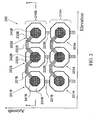
- FIG. 2 illustrates a top view of an embodiment of a cMUT array 200 according to the present invention.
- the cMUT array contains two transducer elements 210, with each of the transducer elements containing three transducer cells 201, 202 and 203.
- the cMUT array 200 can, for example, be similar to that disclosed in U.S. Patent No. 6,271,620 issued August 7, 2001 to Ladabaum and entitled "Acoustic Transducer and Method of Making the Same.”
- Transducer element 210B contains three transducer cells 201B, 202B and 203B.
- Each of the transducer cells 201B, 202B and 203B has a top electrode 241B, 242B and 243B, respectively, and a bottom electrode (shown in FIG. 3), and a void region 231B, 232B and 233B, respectively.
- Transducer cells 201B, 202B and 203B are interconnected along their top electrodes 241B, 242B and 243B in the elevation direction by intra-element interconnects 251B and 252B.
- Corresponding transducer cells 201A-201B, 202A-202B and 203A-203B of adjacent transducer elements 210A-210B are interconnected in the azimuth direction by inter-element interconnects 221B, 222B and 223B to form elevation rows.
- the cross section 3-3 of FIG. 2 is shown in FIG. 3.
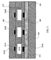
- FIG. 3 illustrates a cross-section of transducer element 210B of an embodiment of the present invention.
- transducer cells 201B, 202B and 203B are formed using the methods, for example, disclosed in co-owned U.S. Patent Application No. 09/898,035 filed July 3, 2001 to Ladabaum and entitled "Method for Making Acoustic Transducer.”
- transducer cell 201B can be constructed in the following manner.
- a layer of thermal oxide 320 is grown over a substrate 310.
- a first conductive layer is then deposited and etched to form the lower electrode 331B. Thereafter, a lower insulation layer 340 is deposited.
- a sacrificial layer is deposited and etched, resulting in sacrificial portions that will ultimately become the void region 231B.
- a middle insulation layer 350 is deposited over the sacrificial portions.
- a second conductive layer is then deposited and etched to form the upper electrode 241B.
- a top insulation layer 360 is then deposited over the top electrode 241B. At this point, the sacrificial portions are etched away through via holes, with the via holes being subsequently filled with insulation material 370.
- the present invention is not meant to limit the specific exemplary geometries of and methods of making the above-described transducer elements and cells. Additionally, the size and shape of the transducer cells are not meant to be limited to a single octagonal design; rather, each transducer cell could be a different size and a different shape from each of the other transducer cells.
- FIG. 4 shows the traditional cMUT array 100 external circuit connections. As shown, typically one azimuth element connection 400 is connected to the top electrode of one series of transducer cells making up a transducer element 110A of the traditional cMUT array 100. All of the bottom electrodes of the cMUT array 100 are commonly connected 410 and, therefore, commonly biased.
- FIG. 5 shows the cMUT array 200 external circuit connections of an embodiment of the present invention.
- the top electrode of each transducer element 210A is connected externally to an azimuth element connection 400.
- the bottom electrodes of corresponding transducer cells of adjacent transducer elements are connected together to form elevation rows.
- Each elevation row is externally connected 510 to a separate output channel of an N by 2 multiplexer 520.
- the multiplexer 520 inputs are a positive 530 and negative 540 bias voltage.
- the multiplexer 520 control signal comes from an EPROM 550 lookup table using a focal zone number 560 pointer.
- the sign of the bias to the elevation rows is changed in order to invert the transmit signal for some of the elevation electrodes.
- This has the effect of creating a Fresnel zone plate. This focusing can be accomplished on transmission as well as reception. However, for simplicity, the following description will be in terms of the transmission, but reception operates in a similar manner.
- the multiplexer routes either the positive or negative bias voltage to the N elevation row connections, based on a lookup table in the EPROM 550.
- Each bias line is an RF ground.
- the EPROM 550 address is, for example, a number provided by the system, based on excitation voltage timing, which tells the probe which focal zone is in use, and optionally information about the center frequency and bandwidth of the excitation pulse. Data in the EPROM 550 converts this to the bias sign arrangement for a given focal zone, and the focal length of the zone plate is determined by these bias signs.
- the zone plate operates similarly to a classical Fresnel lens, but is adapted to cMUT elevation focusing.
- the present invention does not provide for continuous phase-shifting, as in a classical Fresnel lens.
- the multiplexer-EPROM combination of the present invention can be replaced with any commonly known switching and selection circuitry combination.
- such components as: discrete relays, discrete transistors, solid state transistors and other solid state switches can be used.
- a manual pattern selection circuit can be used instead of the EPROM storing multiple, real-time selectable, polarity patterns.
- the positive and negative bias voltages of the present invention can be hard-wired directly to the elevation rows or directly to the switching components.
- the polarity pattern for a particular application is pre-selected and the appropriate bias voltage directly connected to the appropriate elevation row, or elevation row switch, according to the pre-selected polarity pattern.
- the MUT device of the present invention can have a combination of hard-wired and switched bias voltages.
- the positive and negative bias voltages can either be discretely generated off of the MUT device of the present invention, be generated locally with the MUT device of the present invention, or be a combination of discretely and locally generated.
- the bias voltages can, for example, be included in the application probe handle or be generated elsewhere in the application system.
- the bias voltages can, for example, be tied to the MUT device using wires, cables, harnesses, connectors, and the like.
- the bias voltage generation circuitry can be included beside the MUT device, on the same or an adjacent die, or beneath the MUT device, within the MUT device substrate.
- the positive and negative bias voltages can be more numerous than the two shown in FIG. 5.
- each MUT elevation.row can, for example, have its own particular bias voltage, that bias voltage being a particular combination of amplitude and polarity.
- the quantity of bias voltages could outnumber the quantity of elevation rows, with some bias voltages being used for certain applications, while others are used for different applications.
- FIGS. 6A-6C illustrate the feasibility of such an approach.
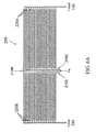
- FIG. 6A illustrates a specific design of an experiment where 3 azimuth elements 210A-C of a cMUT array 200 are connected to a transmit channel.
- the entire array consists of 192 azimuth elements with 10 MHz center frequency, but only 3 azimuth elements are used in the presented experiment.
- the array 200 contains two sets of elevation electrodes 220A and 220B. These electrodes are approximately 100 microns wide, and connect the cMUT cells of adjacent elements 210A, 210B, and 210C in an alternating (i.e., interdigitated) manner to bias voltage V-biasL 540 or V-biasR 530.
- Elements 210A-C are each, for example, approximately 200 microns wide.
- FIG. 6B illustrates the relative strength of a received signal by a hydrophone when the array elements 210A-C of FIG. 6A are biased uniformly in elevation, and when their elevation bias is alternated every 100 microns.
- the transmit pulse in this experiment was small relative to the magnitude of V-bias.
- alternating the bias of cMUT elevation rows can effectively turn off that section of the device, which is evidenced by the approximately 25 dB relative difference at 10 MHz.
- FIG. 6C illustrates the feasibility of another aspect of the embodiment of FIG. 6A, which is that, when transmit voltages are large compared to the magnitude of V-bias, the transducer will operate non-linearly. At these relatively large transmit voltages, it may be necessary to apply different magnitudes of positive and negative bias voltages. As can be seen in FIG. 6C, 25 dB of isolation is possible, when alternating positive and negative bias voltages with magnitudes of 65V and 120V, respectively. Equal magnitude positive and negative bias voltages are less effective at canceling the radiated sound because the pressure created by a relatively large transmit voltage in the direction of bias is different from the pressure created by a relatively large transmit voltage in the opposite direction of the bias.
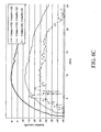
- FIGS. 7A-7B illustrate the improvements of the present invention over the traditional 1D probe and an exemplary, state-of-the-art, multi-row piezoelectric transducer array.
- the present invention provides an improved far-field beam width at both the -3 dB and -20 dB levels. This improvement stems from the use of the Fresnel lensing attributes of the present invention.
- the present invention also improves near-field improvements which are the result of the aperture contol attributes verified in FIGS. 6A-6C.
- the simulations of FIGS. 7A-7B are based on a design of 52 elevation rows, each approximately 100 microns in width, operated with different bias patterns at different focal zones.
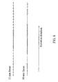
- FIG. 8 illustrates bias voltage patterns for the elevation control lines that can be used to enhance the 15 mm and 50 mm focus (in the range direction) of the probe simulated in FIGS. 7A-7B.
- FIGS. 7A-7B it should be understood that there exists a virtually infinite combination of polarity patterns and bias voltages, and that these combination are meant to be included within the scope of the MUT device of the present invention.
- the traditional polymer lens becomes unnecessary. Such a probe benefits from the fact that losses in the lens are avoided.
- elevation focusing is accomplished using both bias polarity aperture control and some form of mechanical lensing.
- This mechanical lensing can be either conventional polymeric lensing or transducer curvature as disclosed in US-A-2004/0000847. Fresnel lensing for focus optimization beyond the mechanical lens' focal zone can further be applied.
- the bias pattern can be changed between transmit and receive beams so that multi-focal-zone operation, as is known in the art of multi-row probes, is possible.
- the cMUT beam can be steered in the elevation direction.
- the focusing of the cMUT beam can be non-normal to the center of the cMUT elements in the elevation direction.
- the non-normalcy is such that the center point of the peak elevation focus in the elevation direction is off-center to the center of the transducer elements in the elevation direction.
Description
- The present invention generally relates to the field of ultrasonic transducers. More specifically, the present invention relates to elevation beam profile control of capacitive microfabricated ultrasonic transducers.
- An acoustic transducer is an electronic device used to emit and receive sound waves. Ultrasonic transducers are acoustic transducers that operate at frequencies above 20 KHz, and more typically, in the 1-20 MHz range. Ultrasonic transducers are used in medical imaging, non destructive evaluation, and other applications. The most common forms of ultrasonic transducers are piezoelectric transducers. Recently, a different type of ultrasonic transducer, the capacitive microfabricated ultrasonic transducer, has been described and fabricated. Such transducers are described by Haller et al. in U.S. Patent No. 5,619,476 entitled "Electrostatic Ultrasonic Transducer," issued April 9, 1997. The Haller patent describes transducers capable of functioning in a gaseous environment, such as air-coupled transducers. Ladabaum et al., in U.S. Patent No. 5,894,452 entitled, "Microfabricated Ultrasonic Immersion Transducer," issued April 13, 1999, describe an immersion transducer (i.e., a transducer capable of operating in contact with a liquid medium), and, in U.S. Patent No. 5,982,709 entitled, "Acoustic Transducer and Method of Microfabrication," issued November 9, 1999, describe improved structures and methods of microfabricating immersion transducers. In U.S. Patent No. 6,271,620 entitled, "Acoustic Transducer and Method of Making the Same," issued August 7, 2001, Ladabaum describes improvements to microfabricated acoustic transducers which enable competitive performance with piezoelectric transducers. Also US 6 381 197 discloses relevant prior art.
- The basic transduction element of the conventional capacitive microfabricated ultrasonic transducer is a vibrating capacitor. A substrate contains a lower electrode, a thin diaphragm is suspended over the substrate, and a metallization layer serves as an upper electrode. If a DC bias is applied across the lower and upper electrodes, an acoustic wave impinging on the diaphragm will set it in motion, and the variation of electrode separation caused by such motion results in an electrical signal. Conversely, if an AC signal is applied across the biased electrodes, the AC forcing function will set the diaphragm in motion, and this motion emits an acoustic wave in the medium of interest.
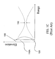
- FIGS. 1A-1C illustrate the naming conventions, as well as the conventional focusing and scanning directions, in a typical transducer array used in medical imaging applications. As shown in FIG. 1A, the
transducer 100 is typically made up of multiple transducer elements 110. Each of the transducer elements 110 includes a plurality of individual transducer cells. The transducer elements 110 are oriented such that their lengths are along the elevation axis, and their widths are along the azimuth axis. The transducer elements 110 are adjacent to one another along the azimuth axis. As shown in FIG. 1B, atransducer array 100 is conventionally focused to afocal spot 150 in the range direction and scanned in the azimuth direction electronically by applying an appropriate time delay to each of the transducer elements 110. As shown in FIG. 1C, focus in the elevation direction has conventionally been achieved with amechanical lens 120. This mechanical focus is sub-optimal because adequate elevation focus is only obtained over a relatively small portion of the usable range. Whereas time-delay focusing in the azimuth plane is possible over the entire field of view (for example 0.5-6 cm for a linear small parts probe), elevation focus is only obtained over a relatively small spatial region ofpeak focus 130. A measure of the elevation focus achievable, as well as the depth of field over which good focus can be achieved, is often described by the term slice thickness. - Traditional ultrasound transducers have poor control of the slice thickness. A
convex lens 120 focuses somewhere in the middle of the usable range, and the focus diverges, or becomes large, at ranges beyond the lens'peak focus 130. This divergent lens focusing creates volume averaging artifacts that obscure small cysts and other clinically relevant, yet small feature size, information. Furthermore, practical physical lenses are often lossy, which further decreases their effective use, because they are made from materials whose speed of sound is slower than the speed of sound in a body. - The elevation focus challenge is well known in the art, and various approaches to improve slice thickness, i.e., to decrease slice thickness, have been taught. For example, U.S. Patent No. 4,670,683 to 't Hoen teaches that electronic phase delays between different subelements in the elevation direction can correct for the slice thickness short-comings of a mechanical lens. However, by requiring delay means in both transmit and receive between "central" and "side" electrodes in elevation, in addition to azimuth delay means, this invention necessitates significant system and transducer complexity.
- U.S. Patent No. 5,301,168 entitled, "Ultrasonic transducer system," filed January 19, 1993, to Miller teaches that a multi-aperture transducer system, where elements are subdivided into multiple elevation apertures, can be used to improve slice thickness. However, the practical complexity of dividing M azimuth channels into N segments in elevation, the N segments grouped into E apertures, is a material disadvantage to this type of design. In order for each of the M channels to be able to have E apertures, switches are necessary in the path of the radio frequency (RF) signal (see, for example, the "combining network" in Figure 8 of the Miller patent). Furthermore, mechanically segmented mechanical lenses are required to achieve good slice thickness for the varying apertures. Because of the cost and complexity of such an arrangement, it is desirable to have an ultrasonic probe with good slice thickness that is simpler to make. It is also desirable to have ultrasonic probes with minimal losses due to the lens losses and without the need for combining network switches in the RF path.
- U.S. Patent No. 5,651,365 to Hanafy et al. teaches that slice thickness can be improved by using two sets of interleaved azimuthal transducer elements, each set having a different elevation aperture. One set is used for optimized focus at a certain range, and the second set is used for an optimized scan at a different range. However, this approach negatively impacts at least one of efficiency, lateral resolution, or frame rate.
- U.S. Patent No. 5,415,175 to Hanafy et al. teaches that by varying the thickness and curvature of a piezoelectric element along the elevation direction, that frequency dependent elevation focusing can be achieved. While this invention is known to those skilled in the art as resulting in ultrasound probes with improved slice thickness performance over conventional probes, the elevation aperture is problematic for low-frequency, relatively narrow-band signals such as those emanating from deep within the tissue. Furthermore, fabrication of these curved surfaces is challenging and consequently expensive.
- U.S. Patent No. 6,381,197 to Savord et al. (e.g., Figures 5A and 5B of the Savord patent) teaches that bias rows in the elevation direction of a microfabricated ultrasonic transducer (MUT) can be connected to bias sources, and that by using these bias sources to selectively energize elevation rows, the elevation aperture of a MUT can be controlled. The Savord patent further teaches that elevation apodization can be achieved by varying the gain in the elevation direction with the bias rows; inherent in the Savord apodization teaching is the complexity of multiple bias sources each at different voltage amplitudes, which is not desirable in practical applications. As taught by the Savord patent, control of aperture and apodization by varying the magnitude of the bias on a MUT is effective only in receive operation. During transmission, the MUT cannot be effectively turned off by bias amplitude alone and is operated outside of its linear range, that is, with the transmit pulse itself essentially biasing the transducer. Thus, it is desirable to provide a means for aperture control that is equally effective in both transmit and receive operation. It is also desirable to provide a simple means for apodization that is effective in both transmit and receive operation.
- It has been realized by the present inventors that a judiciously chosen spatial variation of the sign of the bias voltage is an effective way to control the transmit radiation of a MUT surface. It has been further realized by the present inventors that varying the sign of the bias voltage results in a 180 degree phase shift of the transmitted wavefront, and that this phase shift can be used to create Fresnel lens effects with microfabricated ultrasonic transducers. The Savord patent neither teaches nor suggests such control via spatial distribution of bias polarity.
- Thus, the polarity of bias can modulate the phase, in elevation for example, of both the transmitted and received ultrasonic waveform. This bias-polarity-based phase modulation can be used to effectively control the aperture of a MUT device by providing precise cancellation of both transmitted and received acoustic energy. This bias-polarity-based phase modulation can also be used to create focus in the far field without using a mechanical lens, or to enhance focusing when combined with other lensing means. It can also be used to greatly simplify the design and implementation of probes with excellent slice thickness performance.
- The present invention provides a means to control the phase profile of a capacitive microfabricated ultrasonic transducer (cMUT) element or array of elements by varying the spatial distribution of the sign of the bias voltage on the cMUT.
- The present invention provides a cMUT that can be focused in the elevation direction by varying the sign of the applied bias in the elevation direction. In one aspect of the present invention, elevation focusing is achieved without the aid of a mechanical lens. The cMUT of the present invention provides enhanced multi-row focusing performance without the expense and complexity of the high-voltage switches required in multi-row probes and without the signal degradation that occurs when the RF signal passes through these lossy, high voltage switches. Additionally, the present invention provides a simple and effective means for controlling the aperture of a microfabricated ultrasonic transducer in both transmit and receive operation. The present invention also provides a means for steering the cMUT transmission beam in the elevation direction.
- The present invention achieves these and other goals by providing a method for controlling the elevation slice thickness in both the near field and the far field of a cMUT's usable range. The near field improvement is obtained by reducing both the effective radiating and receiving aperture. In the far field, phase focusing is applied to reduce the slice thickness. In many applications of medical ultrasound, it is advantageous to split the displayed image into several "focal zones" that result from individual transmit firings. Combining these focal zones leads to a composite image more closely approximating a confocal system. With aperture control and phase focusing, the elevation focal length can be altered to match the azimuth focus in each focal zone of the image.
- Both effects are achieved by alternating the polarity of the bias across the elevation aperture. This is achievable in a microfabricated transducer by splitting the common electrode, which is typically continuous, into several elevation electrodes and does not require additional coaxial connections to the transducer, since all of the control is exerted by bias polarity. Further, all of the bias lines to be switched are at RF ground, which eliminates the disadvantages of complexity and signal degradation when switches are in the path of the RF signals.
- Reduction of the effective aperture is implemented by alternating the polarity of the bias on the elevation electrodes with sufficiently fine spatial resolution so as to cancel the fields from the affected elements. Per-focal-zone enhancement to far-field operation works using a Fresnel zone plate.
- The present invention will become more apparent from the detailed description set forth below when taken in conjunction with the drawings in which like reference characters identify correspondingly throughout and wherein:
- FIGS. 1A-1C illustrate the naming conventions, as well as the conventional focusing and scanning directions, in a typical multi-element array transducer used in medical imaging applications;
- FIG. 2 illustrates a top view of a transducer of one embodiment of the present invention;
- FIG. 3 illustrates a cross-section view of a transducer of one embodiment of the present invention;
- FIG. 4 illustrates the electrical schematic for the conventional transducer system;
- FIG. 5 illustrates the electrical schematic for the transducer system of an embodiment of the present invention;
- FIGS. 6A-6C illustrate the experimental design and experimental results verifying the aperture control aspect of the present invention;
- FIGS. 7A-7B illustrate simulation results comparing conventional transducers with the present invention; and
- FIG. 8 illustrates bias voltage patterns corresponding to an embodiment of the present invention.
- The present invention will now be described in detail with reference to the drawings, which are provided as illustrative examples of the invention so as to enable those skilled in the art to practice the invention. Notably, the figures and examples discussed below are not meant to limit the scope of the present invention. Moreover, where certain elements of the present invention can be partially or fully implemented using known components, only those portions of such known components that are necessary for an understanding of the present invention will be described, and detailed descriptions of other portions of such known components will be omitted so as not to obscure the invention. Further, the present invention encompasses present and future known equivalents to the known components that are, by way of illustration, referred to within this disclosure.
- The present invention provides a capacitive microfabricated ultrasonic transducer (cMUT) with control of elevation phase through bias polarity variation. Such control of elevation phase results in simple ultrasonic probes with excellent slice thickness attributes. Furthermore, tight spatial variation of phase results in an effective way to achieve both transmit and receive aperture and apodization control. Further still, such transducers can achieve their elevation focus without the need of a lossy mechanical lens. An exemplary embodiment of the present invention includes a cMUT array, which is made up of transducer elements having transducer cells. The cMUT array is coupled to control circuitry that provides the tight spatial variation of phase using bias polarity.
- FIGS. 2 and 3 illustrate a cMUT array formed according to an embodiment of the present invention. It will become apparent to one skilled in the art that any number of transducer cells can make up a transducer element, and any number of transducer elements can make up a cMUT array. The present invention is intended to incorporate this variability, and not be limited to the exemplary embodiments provided.
- FIG. 2 illustrates a top view of an embodiment of a
cMUT array 200 according to the present invention. As shown in FIG. 2, the cMUT array contains two transducer elements 210, with each of the transducer elements containing three transducer cells 201, 202 and 203. ThecMUT array 200 can, for example, be similar to that disclosed in U.S. Patent No. 6,271,620 issued August 7, 2001 to Ladabaum and entitled "Acoustic Transducer and Method of Making the Same."Transducer element 210B contains threetransducer cells transducer cells top electrode void region Transducer cells top electrodes intra-element interconnects Corresponding transducer cells 201A-201B, 202A-202B and 203A-203B ofadjacent transducer elements 210A-210B are interconnected in the azimuth direction byinter-element interconnects - FIG. 3 illustrates a cross-section of
transducer element 210B of an embodiment of the present invention. As shown in FIG. 3,transducer cells transducer cell 201B can be constructed in the following manner. A layer ofthermal oxide 320 is grown over asubstrate 310. A first conductive layer is then deposited and etched to form thelower electrode 331B. Thereafter, alower insulation layer 340 is deposited. On top of the lower insulation layer, a sacrificial layer is deposited and etched, resulting in sacrificial portions that will ultimately become thevoid region 231B. Amiddle insulation layer 350 is deposited over the sacrificial portions. A second conductive layer is then deposited and etched to form theupper electrode 241B. Atop insulation layer 360 is then deposited over thetop electrode 241B. At this point, the sacrificial portions are etched away through via holes, with the via holes being subsequently filled withinsulation material 370. - The present invention is not meant to limit the specific exemplary geometries of and methods of making the above-described transducer elements and cells. Additionally, the size and shape of the transducer cells are not meant to be limited to a single octagonal design; rather, each transducer cell could be a different size and a different shape from each of the other transducer cells.
- FIG. 4 shows the
traditional cMUT array 100 external circuit connections. As shown, typically oneazimuth element connection 400 is connected to the top electrode of one series of transducer cells making up atransducer element 110A of thetraditional cMUT array 100. All of the bottom electrodes of thecMUT array 100 are commonly connected 410 and, therefore, commonly biased. - FIG. 5 shows the
cMUT array 200 external circuit connections of an embodiment of the present invention. As with the traditional array of FIG. 4, the top electrode of eachtransducer element 210A is connected externally to anazimuth element connection 400. However, in this exemplary embodiment, the bottom electrodes of corresponding transducer cells of adjacent transducer elements are connected together to form elevation rows. Each elevation row is externally connected 510 to a separate output channel of an N by 2multiplexer 520. Themultiplexer 520 inputs are a positive 530 and negative 540 bias voltage. Themultiplexer 520 control signal comes from anEPROM 550 lookup table using afocal zone number 560 pointer. - In operation of the exemplary embodiment of the present invention as shown in FIG. 5, the sign of the bias to the elevation rows is changed in order to invert the transmit signal for some of the elevation electrodes. This has the effect of creating a Fresnel zone plate. This focusing can be accomplished on transmission as well as reception. However, for simplicity, the following description will be in terms of the transmission, but reception operates in a similar manner.
- The multiplexer routes either the positive or negative bias voltage to the N elevation row connections, based on a lookup table in the
EPROM 550. Each bias line is an RF ground. TheEPROM 550 address is, for example, a number provided by the system, based on excitation voltage timing, which tells the probe which focal zone is in use, and optionally information about the center frequency and bandwidth of the excitation pulse. Data in theEPROM 550 converts this to the bias sign arrangement for a given focal zone, and the focal length of the zone plate is determined by these bias signs. - The zone plate, as described above in this embodiment of the present invention, operates similarly to a classical Fresnel lens, but is adapted to cMUT elevation focusing. For example, if the center of the elevation electrode is located at yi , then the phase φ i required for focusing in a classical Fresnel lens is:

- It will be understood by those skilled in the art that there are numerous methods and circuits by which positive and negative bias voltages can be connected to and combined with the elevation rows of the present invention. These additional bias voltage connection methods and circuits are meant to be included within the scope of the present invention.
- Specifically, in another embodiment, the multiplexer-EPROM combination of the present invention can be replaced with any commonly known switching and selection circuitry combination. For example, such components as: discrete relays, discrete transistors, solid state transistors and other solid state switches can be used. Likewise, instead of the EPROM storing multiple, real-time selectable, polarity patterns, a manual pattern selection circuit can be used. Further, the positive and negative bias voltages of the present invention can be hard-wired directly to the elevation rows or directly to the switching components. In this embodiment, the polarity pattern for a particular application is pre-selected and the appropriate bias voltage directly connected to the appropriate elevation row, or elevation row switch, according to the pre-selected polarity pattern. Finally, in this embodiment, the MUT device of the present invention can have a combination of hard-wired and switched bias voltages.
- In a further embodiment, the positive and negative bias voltages can either be discretely generated off of the MUT device of the present invention, be generated locally with the MUT device of the present invention, or be a combination of discretely and locally generated. In the first aspect of this embodiment, discrete generation, the bias voltages can, for example, be included in the application probe handle or be generated elsewhere in the application system. In this aspect, the bias voltages can, for example, be tied to the MUT device using wires, cables, harnesses, connectors, and the like. In the second aspect of this embodiment, local generation, the bias voltage generation circuitry can be included beside the MUT device, on the same or an adjacent die, or beneath the MUT device, within the MUT device substrate.
- In yet another embodiment, the positive and negative bias voltages can be more numerous than the two shown in FIG. 5. Specifically, in operation, each MUT elevation.row can, for example, have its own particular bias voltage, that bias voltage being a particular combination of amplitude and polarity. Additionally, in this embodiment, the quantity of bias voltages could outnumber the quantity of elevation rows, with some bias voltages being used for certain applications, while others are used for different applications.
- For best image quality, it is necessary to be able to reduce the elevation aperture in the near field. Alternating the bias, as in an embodiment of the present invention, when the elevation electrodes are on the order of half wavelength across, is an effective method to cancel the sound output and can be used for aperture control and apodization. FIGS. 6A-6C illustrate the feasibility of such an approach.
- FIG. 6A illustrates a specific design of an experiment where 3
azimuth elements 210A-C of acMUT array 200 are connected to a transmit channel. The entire array consists of 192 azimuth elements with 10 MHz center frequency, but only 3 azimuth elements are used in the presented experiment. Thearray 200 contains two sets ofelevation electrodes adjacent elements biasL 540 or V-biasR 530.Elements 210A-C are each, for example, approximately 200 microns wide. - FIG. 6B illustrates the relative strength of a received signal by a hydrophone when the
array elements 210A-C of FIG. 6A are biased uniformly in elevation, and when their elevation bias is alternated every 100 microns. The transmit pulse in this experiment was small relative to the magnitude of V-bias. As can be seen in FIG. 6B, alternating the bias of cMUT elevation rows can effectively turn off that section of the device, which is evidenced by the approximately 25 dB relative difference at 10 MHz. - FIG. 6C illustrates the feasibility of another aspect of the embodiment of FIG. 6A, which is that, when transmit voltages are large compared to the magnitude of V-bias, the transducer will operate non-linearly. At these relatively large transmit voltages, it may be necessary to apply different magnitudes of positive and negative bias voltages. As can be seen in FIG. 6C, 25 dB of isolation is possible, when alternating positive and negative bias voltages with magnitudes of 65V and 120V, respectively. Equal magnitude positive and negative bias voltages are less effective at canceling the radiated sound because the pressure created by a relatively large transmit voltage in the direction of bias is different from the pressure created by a relatively large transmit voltage in the opposite direction of the bias.
- FIGS. 7A-7B illustrate the improvements of the present invention over the traditional 1D probe and an exemplary, state-of-the-art, multi-row piezoelectric transducer array. As shown in the simulations, the present invention provides an improved far-field beam width at both the -3 dB and -20 dB levels. This improvement stems from the use of the Fresnel lensing attributes of the present invention. The present invention also improves near-field improvements which are the result of the aperture contol attributes verified in FIGS. 6A-6C. The simulations of FIGS. 7A-7B are based on a design of 52 elevation rows, each approximately 100 microns in width, operated with different bias patterns at different focal zones.
- Since the focusing and aperture control of the present invention is unusual, it is possible, but unlikely, that assigning the bias pattern by a simple algorithm such as the Fresnel scheme described above will provide the optimized performance. Thus, the EPROM architecture has been introduced so that bias patterns resulting from time-consuming optimization computations can be practically accessed in a real probe. For example, FIG. 8 illustrates bias voltage patterns for the elevation control lines that can be used to enhance the 15 mm and 50 mm focus (in the range direction) of the probe simulated in FIGS. 7A-7B. However, it should be understood that there exists a virtually infinite combination of polarity patterns and bias voltages, and that these combination are meant to be included within the scope of the MUT device of the present invention.
- In an embodiment of the present invention, with elevation focusing accomplished using alternating bias, the traditional polymer lens becomes unnecessary. Such a probe benefits from the fact that losses in the lens are avoided. In another embodiment of the present invention, elevation focusing is accomplished using both bias polarity aperture control and some form of mechanical lensing. This mechanical lensing can be either conventional polymeric lensing or transducer curvature as disclosed in US-A-2004/0000847. Fresnel lensing for focus optimization beyond the mechanical lens' focal zone can further be applied. In yet another embodiment of the present invention, the bias pattern can be changed between transmit and receive beams so that multi-focal-zone operation, as is known in the art of multi-row probes, is possible.
- In another aspect of the present invention, the cMUT beam can be steered in the elevation direction. When the amplitudes and the polarities of the bias voltages are varied, the focusing of the cMUT beam can be non-normal to the center of the cMUT elements in the elevation direction. The non-normalcy is such that the center point of the peak elevation focus in the elevation direction is off-center to the center of the transducer elements in the elevation direction.
- Although the present invention has been particularly described with reference to the preferred embodiments thereof, it should be readily apparent to those of ordinary skill in the art that changes and modifications in the form and details thereof may be made without departing from the scope of the invention. For example, those skilled in the art will understand that variations can be made in the type, number and arrangement of components illustrated in the above diagrams; the multiplexer-EPROM configuration can easily be replaced with other components. Further, more than two bias voltages with varying combinations of magnitudes and pluralities can be used by, and are intended to be within the scope of, the present invention. It is intended that the appended claims include such changes, modifications and combinations.
Claims (47)
- A transducer element, comprising:a plurality of transducer cells, each transducer cell including a pair of electrodes; anda circuit adapted to apply one of a plurality of bias voltages to each pair of electrodes,wherein:the plurality of bias voltages include a positive bias voltage and a negative bias voltage;the positive bias voltage is applied as the one bias voltage to at least a first pair of electrodes; andthe negative bias voltage is applied as the one bias voltage to at least a second pair of electrodes.
- The transducer element of claim 1, wherein:each pair of electrodes includes a first electrode and a second electrode; andthe circuit comprises:a first connection node including the first electrode of each pair of electrodes;a plurality of second connection nodes, each second connection node including the second electrode of at least one pair of electrodes; andconnecting circuitry adapted to couple the plurality of bias voltages between the first connection node and the plurality of second connection nodes.
- The transducer element of claim 2, wherein the connecting circuitry comprises at least one of:at least one multiplexer;at least one relay;at least one transistor; andhard-wiring.
- The transducer element of claim 3, wherein the connecting circuitry comprises:a plurality of bias voltage inputs connected to the plurality of bias voltages;a plurality of bias voltage outputs connected to the plurality of second connection nodes;
anda selection input, the selection input connected to a designated bias voltage pattern. - The transducer element of claim 4, further comprising selection circuitry adapted to identify the designated bias voltage pattern.
- The transducer element of claim 5, wherein the selection circuitry comprises:a memory unit, the memory unit including a look-up table containing at least one bias voltage pattern; anda means for pointing to the designated bias voltage pattern from within the look-up table.
- The transducer element of claim 6, wherein the memory unit is an erasable, programmable, read only memory (EPROM).
- The transducer element of claim 6, wherein:the at least one bias voltage pattern corresponds to a focal zone number; andthe means for pointing includes a system generated focal zone number pointer.
- The transducer element of claim 1, wherein the positive bias voltage has an amplitude different than the negative bias voltage.
- The transducer element of claim 1, wherein the plurality of bias voltages are generated discretely and separately from the transducer element
- The transducer element of claim 1, wherein the plurality of bias voltages are generated locally to the transducer element.
- The transducer element of claim 1, wherein the circuit varies, as a function of time, an amplitude and a polarity for at least one bias voltage of the plurality of bias voltages.
- The transducer element of claim 12, wherein the amplitude and the polarity are varied such that elevation focus in a range direction is different from that of a uniformly biased transducer element.
- The transducer element of claim 12, wherein the amplitude and the polarity are varied such that a center point of a peak elevation focus in an elevation direction is off-center to the transducer element in the elevation direction.
- A transducer array, comprising:a plurality of transducer elements according to any of claims 1 to 14.
- The transducer array of claim 15, wherein:each pair of electrodes includes a first electrode and a second electrode; andthe circuit comprises:a plurality of first connection nodes, each first connection node including the first electrodes of the plurality of transducer cells of at least one transducer element;a plurality of second connection nodes, each second connection node including the second electrode of at least one transducer cell of each transducer element; andconnecting circuitry adapted to couple the plurality of bias voltages between the plurality of first connection nodes and the plurality of second connection nodes.
- The transducer array of claim 16, wherein the connecting circuitry comprises at least one of:at least one multiplexer;at least one relay;at least one transistor; andhard-wiring.
- The transducer array of claim 17, wherein the connecting circuitry comprises:a plurality of bias voltage inputs connected to the plurality of bias voltages;a plurality of bias voltage outputs connected to the plurality of second connection nodes; anda selection input, the selection input connect to a designated bias voltage pattern.
- The transducer array of claim 18, further comprising selection circuitry adapted to identify the designated bias voltage pattern.
- The transducer array of claim 19, wherein the selection circuitry comprises:a memory unit, the memory unit including a look-up table containing at least one bias voltage pattern; anda means for pointing to the designated bias voltage pattern from within the look-up table.
- The transducer array of claim 20, wherein the memory unit is an erasable, programmable, read only memory (EPROM).
- The transducer array of claim 20, wherein:the at least one bias voltage pattern further includes a focal zone number; andthe means for pointing includes a system generated focal zone number pointer.
- The transducer array of claim 22, wherein the system generated focal zone number pointer is inferred from a timing of an excitation voltage applied to each of the plurality of transducer elements.
- The transducer array of claim 15, wherein the positive bias voltage has an amplitude different than the negative bias voltage.
- The transducer array of claim 15, wherein the plurality of bias voltages are generated discretely and separately from the transducer element.
- The transducer array of claim 15, wherein the plurality of bias voltages are generated locally to the transducer element.
- The transducer array of claim 15, wherein the circuit varies, as a function of time, an amplitude and a polarity for at least one bias voltage of the plurality of bias voltages.
- The transducer array of claim 27, wherein the amplitude and the polarity are varied such that elevation focus in a range direction is different from that of a uniformly biased transducer array.
- The transducer array of claim 27, wherein the amplitude and the polarity are varied such that a center point of a peak elevation focus in an elevation direction is off-center to the transducer array in the elevation direction.
- The transducer array of claim 16, wherein:the plurality of transducer elements are adjacent to each other in an azimuth direction such that consecutively numbered transducer cells of a first transducer element are aligned in an elevation direction with like consecutively numbered transducer cells of all other transducer elements; andeach second connection node includes a contiguous subset of the second electrodes of the consecutively numbered transducer cells of adjacent transducer elements.
- The transducer array of claim 30, wherein:the plurality of transducer elements include at least 36 transducer elements;each transducer element has a first width in the azimuth direction of at least one-half wavelength at a frequency of interest;each first connection node is connected to an RF channel of an ultrasound system; andthe contiguous subset has a second width in the elevation direction of at least one-quarter wavelength at the frequency of interest.
- A method of controlling a transducer array, the transducer array including a plurality of transducer elements, each transducer element including a plurality of transducer cells, each transducer cell including a pair of electrodes, comprising the step of:applying one of a plurality of bias voltages to each pair of electrodes, wherein:the plurality of bias voltages include a positive bias voltage and a negative bias voltage;the positive bias voltage is applied as the one bias voltage to at least a first pair of electrodes; andthe negative bias voltage is applied as the one bias voltage to at least a second pair of electrodes.
- The method of claim 32, further comprising the steps of:connecting a first electrode of each pair of electrodes of the plurality of transducer cells of at least one transducer element to form a plurality of first connection nodes;connecting a second electrode of each pair of electrodes of at least one transducer cell of each transducer element to form a plurality of second connection nodes, andcoupling the plurality of bias voltages between the plurality of first connection nodes and the plurality of second connection nodes.
- The method of claim 33, wherein the step of coupling uses a multiplexer.
- The method of claim 33, wherein the step of coupling uses connecting circuitry comprising at least one of:at least one multiplexer;at least one relay;at least one transistor; andhard-wiring.
- The method of claim 34, wherein using the connecting circuitry comprises:connecting the plurality of bias voltages to a plurality of bias voltage inputs of the multiplexer;connecting the plurality of second connection nodes to a plurality of bias voltage outputs of the multiplexer; andconnecting a designated bias voltage pattern to a selection input of the multiplexer.
- The method of claim 36, further comprising the step of identifying the designated bias voltage pattern.
- The method of claim 37, wherein identifying the designated bias voltage pattern comprises:connecting a memory unit to the selection input, the memory unit including a look-up table containing at least one bias voltage pattern; andpointing to the designated bias voltage pattern from within the look-up table.
- The method of claim 38, wherein the memory unit is an erasable, programmable, read only memory (EPROM).
- The method of claim 38, wherein:the at least one bias voltage pattern further includes a focal zone number; andpointing includes using a system generated focal zone number pointer.
- The method of claim 40, wherein the system generated focal zone number pointer is inferred from a timing of an excitation voltage applied to each of the plurality of transducer elements.
- The method of claim 32, wherein the positive bias voltage has an amplitude of different magnitude than the negative bias voltage.
- The method of claim 32, wherein the step of applying the plurality of bias voltages varies, as a function of time, an amplitude and a polarity for at least one of the plurality of bias voltages.
- The method of claim 43, wherein the amplitude and the polarity are varied such that an elevation focus in a range direction is different from that of a uniformly biased transducer array.
- The method of claim 43, wherein the amplitude and the polarity are varied such that a center point of a peak elevation focus in an elevation direction is off-center to the transducer array in the elevation direction.
- The method of claim 33, further comprising the steps of:aligning the plurality of transducer elements adjacent to each other in an azimuth direction such that consecutively numbered transducer cells of a first transducer element are aligned in an elevation direction with like consecutively numbered transducer cells of all other transducer elements; andincluding in each second connection node a contiguous subset of the second electrodes of the consecutively numbered transducer cells of adjacent transducer elements.
- The method of claim 46, wherein:the plurality of transducer elements include at least 36 transducer elements;each transducer element has a first width in the azimuth direction of at least one-half wavelength at a frequency of interest;each first connection node is connected to an RF channel of an ultrasound system; andthe contiguous subset has a second width in the elevation direction of at least one-quarter wavelength at the frequency of interest.
Applications Claiming Priority (3)
| Application Number | Priority Date | Filing Date | Title |
|---|---|---|---|
| US367106 | 2003-02-14 | ||
| US10/367,106 US7087023B2 (en) | 2003-02-14 | 2003-02-14 | Microfabricated ultrasonic transducers with bias polarity beam profile control and method of operating the same |
| PCT/US2004/002740 WO2004075165A1 (en) | 2003-02-14 | 2004-01-29 | Microfabricated ultrasonic transducers with bias polarity beam profile control |
Publications (2)
| Publication Number | Publication Date |
|---|---|
| EP1593115A1 EP1593115A1 (en) | 2005-11-09 |
| EP1593115B1 true EP1593115B1 (en) | 2007-05-02 |
Family
ID=32849901
Family Applications (1)
| Application Number | Title | Priority Date | Filing Date |
|---|---|---|---|
| EP04706549A Expired - Fee Related EP1593115B1 (en) | 2003-02-14 | 2004-01-29 | Microfabricated ultrasonic transducers with bias polarity beam profile control |
Country Status (6)
| Country | Link |
|---|---|
| US (1) | US7087023B2 (en) |
| EP (1) | EP1593115B1 (en) |
| JP (1) | JP4422718B2 (en) |
| CN (1) | CN1833273B (en) |
| DE (1) | DE602004006232T2 (en) |
| WO (1) | WO2004075165A1 (en) |
Families Citing this family (83)
| Publication number | Priority date | Publication date | Assignee | Title |
|---|---|---|---|---|
| US7289837B2 (en) | 2002-10-01 | 2007-10-30 | Nellcor Puritan Bennett Incorpoated | Forehead sensor placement |
| US7618373B2 (en) * | 2003-02-14 | 2009-11-17 | Siemens Medical Solutions Usa, Inc. | Microfabricated ultrasonic transducer array for 3-D imaging and method of operating the same |
| US7635332B2 (en) * | 2003-02-14 | 2009-12-22 | Siemens Medical Solutions Usa, Inc. | System and method of operating microfabricated ultrasonic transducers for harmonic imaging |
| US7780597B2 (en) * | 2003-02-14 | 2010-08-24 | Siemens Medical Solutions Usa, Inc. | Method and apparatus for improving the performance of capacitive acoustic transducers using bias polarity control and multiple firings |
| US20040190377A1 (en) * | 2003-03-06 | 2004-09-30 | Lewandowski Robert Stephen | Method and means for isolating elements of a sensor array |
| US7443765B2 (en) * | 2003-03-06 | 2008-10-28 | General Electric Company | Reconfigurable linear sensor arrays for reduced channel count |
| US7047056B2 (en) | 2003-06-25 | 2006-05-16 | Nellcor Puritan Bennett Incorporated | Hat-based oximeter sensor |
| US20050043627A1 (en) * | 2003-07-17 | 2005-02-24 | Angelsen Bjorn A.J. | Curved ultrasound transducer arrays manufactured with planar technology |
| US8412297B2 (en) | 2003-10-01 | 2013-04-02 | Covidien Lp | Forehead sensor placement |
| US7427825B2 (en) * | 2004-03-12 | 2008-09-23 | Siemens Medical Solutions Usa, Inc. | Electrical interconnections and methods for membrane ultrasound transducers |
| US20050215909A1 (en) * | 2004-03-19 | 2005-09-29 | Siemens Medical Solutions Usa, Inc. | Electric field control for capacitive micromachined ultrasound transducers |
| JP5179058B2 (en) * | 2004-10-15 | 2013-04-10 | 株式会社日立メディコ | Ultrasonic diagnostic equipment |
| US7914458B2 (en) | 2005-05-05 | 2011-03-29 | Volcano Corporation | Capacitive microfabricated ultrasound transducer-based intravascular ultrasound probes |
| CN101160098B (en) * | 2005-05-09 | 2011-01-05 | 株式会社日立医药 | Ultrasonograph |
| TWI260940B (en) * | 2005-06-17 | 2006-08-21 | Ind Tech Res Inst | Method for producing polymeric capacitive ultrasonic transducer |
| US7229251B2 (en) * | 2005-05-31 | 2007-06-12 | Sikorsky Aircraft Corporation | Rotor hub fairing system for a counter-rotating, coaxial rotor system |
| US20070079658A1 (en) * | 2005-09-23 | 2007-04-12 | Siemens Medical Solutions Usa, Inc. | Rotating aperture for ultrasound imaging with a capacitive membrane or electrostrictive ultrasound transducer |
| JP4776349B2 (en) * | 2005-11-14 | 2011-09-21 | 株式会社日立メディコ | Ultrasonic imaging device |
| US8764664B2 (en) | 2005-11-28 | 2014-07-01 | Vizyontech Imaging, Inc. | Methods and apparatus for conformable medical data acquisition pad and configurable imaging system |
| US8038620B2 (en) * | 2005-12-20 | 2011-10-18 | General Electric Company | Fresnel zone imaging system and method |
| US8105239B2 (en) * | 2006-02-06 | 2012-01-31 | Maui Imaging, Inc. | Method and apparatus to visualize the coronary arteries using ultrasound |
| WO2007099824A1 (en) * | 2006-02-23 | 2007-09-07 | Hitachi Medical Corporation | Ultrasonographic device and ultrasonographic method |
| JP4699259B2 (en) * | 2006-03-31 | 2011-06-08 | 株式会社日立製作所 | Ultrasonic transducer |
| WO2007115283A2 (en) * | 2006-04-04 | 2007-10-11 | Kolo Technologies, Inc. | Modulation in micromachined ultrasonic transducers |
| JP4852356B2 (en) * | 2006-06-27 | 2012-01-11 | 株式会社日立メディコ | Ultrasonic diagnostic equipment |
| WO2008051639A2 (en) * | 2006-10-25 | 2008-05-02 | Maui Imaging, Inc. | Method and apparatus to produce ultrasonic images using multiple apertures |
| JP4961260B2 (en) * | 2007-05-16 | 2012-06-27 | 株式会社日立製作所 | Semiconductor device |
| EP2168493A4 (en) * | 2007-07-11 | 2017-05-31 | Hitachi, Ltd. | Ultrasonic probe, and ultrasonic diagnosing device |
| US7839722B2 (en) * | 2007-09-20 | 2010-11-23 | Siemens Medical Solutions Usa, Inc. | Microfabricated acoustic transducer with a multilayer electrode |
| US8641628B2 (en) * | 2007-09-26 | 2014-02-04 | Siemens Medical Solutions Usa, Inc. | Aperture synthesis using cMUTs |
| US9788813B2 (en) | 2010-10-13 | 2017-10-17 | Maui Imaging, Inc. | Multiple aperture probe internal apparatus and cable assemblies |
| US9282945B2 (en) | 2009-04-14 | 2016-03-15 | Maui Imaging, Inc. | Calibration of ultrasound probes |
| US8792964B2 (en) * | 2008-03-12 | 2014-07-29 | Siemens Aktiengesellschaft | Method and apparatus for conducting an interventional procedure involving heart valves using a robot-based X-ray device |
| DE102008013858A1 (en) * | 2008-03-12 | 2009-09-24 | Siemens Aktiengesellschaft | Catheter device and associated medical examination and treatment device |
| DE102008013854A1 (en) * | 2008-03-12 | 2009-09-24 | Siemens Aktiengesellschaft | Catheter and associated medical examination and treatment facility |
| WO2010017445A2 (en) | 2008-08-08 | 2010-02-11 | Maui Imaging, Inc. | Imaging with multiple aperture medical ultrasound and synchronization of add-on systems |
| US8133182B2 (en) | 2008-09-09 | 2012-03-13 | Siemens Medical Solutions Usa, Inc. | Multi-dimensional transducer array and beamforming for ultrasound imaging |
| JP5397670B2 (en) * | 2008-09-16 | 2014-01-22 | 株式会社ニデック | Non-contact ultrasonic tonometer |
| US8364220B2 (en) | 2008-09-25 | 2013-01-29 | Covidien Lp | Medical sensor and technique for using the same |
| US8257274B2 (en) | 2008-09-25 | 2012-09-04 | Nellcor Puritan Bennett Llc | Medical sensor and technique for using the same |
| JP5409251B2 (en) * | 2008-11-19 | 2014-02-05 | キヤノン株式会社 | Electromechanical transducer and method for manufacturing the same |
| DE102009014489B4 (en) * | 2009-03-23 | 2011-03-10 | Siemens Aktiengesellschaft | Catheter and medical device |
| DE102009014462B4 (en) * | 2009-03-23 | 2019-01-17 | Siemens Healthcare Gmbh | A blood pump, medical device, comprising a blood pump and methods for assisting the placement of a blood pump |
| US8515515B2 (en) | 2009-03-25 | 2013-08-20 | Covidien Lp | Medical sensor with compressible light barrier and technique for using the same |
| US8781548B2 (en) | 2009-03-31 | 2014-07-15 | Covidien Lp | Medical sensor with flexible components and technique for using the same |
| KR101659723B1 (en) | 2009-04-14 | 2016-09-26 | 마우이 이미징, 인코포레이티드 | Multiple aperture ultrasound array alignment fixture |
| JP5473579B2 (en) | 2009-12-11 | 2014-04-16 | キヤノン株式会社 | Control device for capacitive electromechanical transducer and control method for capacitive electromechanical transducer |
| DE102010007177B4 (en) * | 2010-02-08 | 2017-06-22 | Siemens Healthcare Gmbh | Display method for an image of the interior of a vessel located in front of a widening device and display device corresponding thereto |
| WO2011103303A2 (en) | 2010-02-18 | 2011-08-25 | Maui Imaging, Inc. | Point source transmission and speed-of-sound correction using mult-aperture ultrasound imaging |
| US9066674B2 (en) * | 2010-03-17 | 2015-06-30 | Siemens Medical Solutions Usa, Inc. | Motion synchronized destruction for three-dimensional reperfusion mapping in medical diagnostic ultrasound imaging |
| WO2012051308A2 (en) | 2010-10-13 | 2012-04-19 | Maui Imaging, Inc. | Concave ultrasound transducers and 3d arrays |
| US8498178B2 (en) | 2010-12-23 | 2013-07-30 | Analog Devices, Inc. | Acoustic transducer chip |
| KR20120080882A (en) * | 2011-01-10 | 2012-07-18 | 삼성전자주식회사 | Acoustic transducer and method of driving the same |
| EP2785253B1 (en) | 2011-12-01 | 2023-11-15 | Maui Imaging, Inc. | Motion detection using ping-based and multiple aperture doppler ultrasound |
| KR20140107648A (en) | 2011-12-29 | 2014-09-04 | 마우이 이미징, 인코포레이티드 | M-mode ultrasound imaging of arbitrary paths |
| EP2816958B1 (en) | 2012-02-21 | 2020-03-25 | Maui Imaging, Inc. | Determining material stiffness using multiple aperture ultrasound |
| CN104203110B (en) | 2012-03-26 | 2017-06-06 | 毛伊图像公司 | System and method for improving ultrasonoscopy quality by the application weighting factor |
| JP6024156B2 (en) * | 2012-03-30 | 2016-11-09 | セイコーエプソン株式会社 | Ultrasonic measuring device, electronic device, diagnostic device and ultrasonic device |
| JP2014023670A (en) * | 2012-07-26 | 2014-02-06 | Ge Medical Systems Global Technology Co Llc | Ultrasonic diagnostic apparatus and control program for the same |
| KR102176193B1 (en) | 2012-08-10 | 2020-11-09 | 마우이 이미징, 인코포레이티드 | Calibration of Multiple Aperture Ultrasound Probes |
| EP2887879B1 (en) | 2012-08-21 | 2021-05-26 | Maui Imaging, Inc. | Method of ultrasound imaging |
| JP6011235B2 (en) | 2012-10-17 | 2016-10-19 | セイコーエプソン株式会社 | Ultrasonic measuring device, probe head, ultrasonic probe, electronic device and ultrasonic diagnostic device |
| US9510806B2 (en) | 2013-03-13 | 2016-12-06 | Maui Imaging, Inc. | Alignment of ultrasound transducer arrays and multiple aperture probe assembly |
| DE102013217362A1 (en) * | 2013-08-30 | 2015-03-05 | Robert Bosch Gmbh | sensor arrangement |
| US9883848B2 (en) | 2013-09-13 | 2018-02-06 | Maui Imaging, Inc. | Ultrasound imaging using apparent point-source transmit transducer |
| JP6221582B2 (en) * | 2013-09-30 | 2017-11-01 | セイコーエプソン株式会社 | Ultrasonic device and probe, electronic apparatus and ultrasonic imaging apparatus |
| JP6722656B2 (en) | 2014-08-18 | 2020-07-15 | マウイ イマギング,インコーポレーテッド | Network-based ultrasound imaging system |
| JP2016097033A (en) * | 2014-11-20 | 2016-05-30 | キヤノン株式会社 | Capacitance type transducer and subject information acquisition device |
| CN108027436A (en) | 2015-09-08 | 2018-05-11 | 达尔豪斯大学 | With reference to the system and method for phased array and the Fresnel zone plate beam forming of the Fresnel sub-aperture using delay correction |
| US9987661B2 (en) | 2015-12-02 | 2018-06-05 | Butterfly Network, Inc. | Biasing of capacitive micromachined ultrasonic transducers (CMUTs) and related apparatus and methods |
| CN105411625B (en) * | 2015-12-28 | 2019-06-07 | 中国科学院苏州生物医学工程技术研究所 | Diagnosis and treatment integrative ultrasonic system based on capacitance type micromachined ultrasonic energy converter planar battle array |
| JP6705180B2 (en) * | 2016-01-21 | 2020-06-03 | コニカミノルタ株式会社 | Ultrasonic diagnostic equipment |
| WO2017132517A1 (en) | 2016-01-27 | 2017-08-03 | Maui Imaging, Inc. | Ultrasound imaging with sparse array probes |
| WO2017149421A1 (en) * | 2016-03-03 | 2017-09-08 | Koninklijke Philips N.V. | Ultrasonic cmut transducer array with improved depth of field |
| US11061124B2 (en) | 2016-10-21 | 2021-07-13 | The Governors Of The University Of Alberta | System and method for ultrasound imaging |
| WO2018107299A1 (en) * | 2016-12-15 | 2018-06-21 | Dalhousie University | Systems and methods for ultrasound beamforming using coherently compounded fresnel focusing |
| EP4289521A3 (en) * | 2016-12-22 | 2024-03-27 | Koninklijke Philips N.V. | Systems and methods of operation of capacitive radio frequency micro-electromechanical switches |
| CA3064279A1 (en) * | 2017-06-23 | 2018-12-27 | Butterfly Network, Inc. | Differential ultrasonic transducer element for ultrasound devices |
| US10613058B2 (en) * | 2017-06-27 | 2020-04-07 | Kolo Medical, Ltd. | CMUT signal separation with multi-level bias control |
| US11150344B2 (en) | 2018-01-26 | 2021-10-19 | Roger Zemp | 3D imaging using a bias-sensitive crossed-electrode array |
| EP3597313A1 (en) * | 2018-07-18 | 2020-01-22 | Koninklijke Philips N.V. | Ultrasound imaging system using an array of transducer elements and an imaging method |
| EP3827906A1 (en) | 2019-11-29 | 2021-06-02 | Imec VZW | A phased array ultrasound device for creating a pressure focus point |
| CN112683389B (en) * | 2021-01-13 | 2022-11-01 | 山东省科学院海洋仪器仪表研究所 | Longitudinal vibration vector hydrophone |
Family Cites Families (19)
| Publication number | Priority date | Publication date | Assignee | Title |
|---|---|---|---|---|
| US4736630A (en) | 1985-08-05 | 1988-04-12 | Hitachi, Ltd. | Apparatus and method for sending out and receiving ultrasonic wave signals |
| US4670683A (en) | 1985-08-20 | 1987-06-02 | North American Philips Corporation | Electronically adjustable mechanical lens for ultrasonic linear array and phased array imaging |
| DE3732131A1 (en) | 1987-09-24 | 1989-04-06 | Wolf Gmbh Richard | FOCUSING ULTRASONIC transducer |
| US5301168A (en) | 1993-01-19 | 1994-04-05 | Hewlett-Packard Company | Ultrasonic transducer system |
| US5510824A (en) * | 1993-07-26 | 1996-04-23 | Texas Instruments, Inc. | Spatial light modulator array |
| US5415175A (en) | 1993-09-07 | 1995-05-16 | Acuson Corporation | Broadband phased array transducer design with frequency controlled two dimension capability and methods for manufacture thereof |
| US5490512A (en) | 1994-06-16 | 1996-02-13 | Siemens Medical Systems, Inc. | Elevation direction focusing in ultrasound transducer arrays |
| US5619476A (en) | 1994-10-21 | 1997-04-08 | The Board Of Trustees Of The Leland Stanford Jr. Univ. | Electrostatic ultrasonic transducer |
| US5894452A (en) | 1994-10-21 | 1999-04-13 | The Board Of Trustees Of The Leland Stanford Junior University | Microfabricated ultrasonic immersion transducer |
| US5651365A (en) | 1995-06-07 | 1997-07-29 | Acuson Corporation | Phased array transducer design and method for manufacture thereof |
| US6046840A (en) * | 1995-06-19 | 2000-04-04 | Reflectivity, Inc. | Double substrate reflective spatial light modulator with self-limiting micro-mechanical elements |
| US5768007A (en) * | 1995-09-11 | 1998-06-16 | Texas Instruments Incorporated | Phase matched reset for digital micro-mirror device |
| US5671746A (en) | 1996-07-29 | 1997-09-30 | Acuson Corporation | Elevation steerable ultrasound transducer array |
| US5982709A (en) | 1998-03-31 | 1999-11-09 | The Board Of Trustees Of The Leland Stanford Junior University | Acoustic transducers and method of microfabrication |
| US6279399B1 (en) | 1998-08-03 | 2001-08-28 | Vingmed Sound A/S | Multi-dimensional transducer array apparatus |
| US6381197B1 (en) | 1999-05-11 | 2002-04-30 | Bernard J Savord | Aperture control and apodization in a micro-machined ultrasonic transducer |
| US6271620B1 (en) * | 1999-05-20 | 2001-08-07 | Sen Corporation | Acoustic transducer and method of making the same |
| US6246158B1 (en) * | 1999-06-24 | 2001-06-12 | Sensant Corporation | Microfabricated transducers formed over other circuit components on an integrated circuit chip and methods for making the same |
| US6443901B1 (en) * | 2000-06-15 | 2002-09-03 | Koninklijke Philips Electronics N.V. | Capacitive micromachined ultrasonic transducers |
-
2003
- 2003-02-14 US US10/367,106 patent/US7087023B2/en not_active Expired - Fee Related
-
2004
- 2004-01-29 CN CN2004800072945A patent/CN1833273B/en not_active Expired - Fee Related
- 2004-01-29 DE DE602004006232T patent/DE602004006232T2/en not_active Expired - Lifetime
- 2004-01-29 EP EP04706549A patent/EP1593115B1/en not_active Expired - Fee Related
- 2004-01-29 WO PCT/US2004/002740 patent/WO2004075165A1/en active IP Right Grant
- 2004-01-29 JP JP2006503208A patent/JP4422718B2/en not_active Expired - Fee Related
Non-Patent Citations (1)
| Title |
|---|
| None * |
Also Published As
| Publication number | Publication date |
|---|---|
| DE602004006232D1 (en) | 2007-06-14 |
| DE602004006232T2 (en) | 2008-02-07 |
| JP4422718B2 (en) | 2010-02-24 |
| CN1833273A (en) | 2006-09-13 |
| EP1593115A1 (en) | 2005-11-09 |
| CN1833273B (en) | 2010-12-22 |
| JP2006519556A (en) | 2006-08-24 |
| WO2004075165A1 (en) | 2004-09-02 |
| US7087023B2 (en) | 2006-08-08 |
| US20040160144A1 (en) | 2004-08-19 |
| WO2004075165B1 (en) | 2006-04-27 |
Similar Documents
| Publication | Publication Date | Title |
|---|---|---|
| EP1593115B1 (en) | Microfabricated ultrasonic transducers with bias polarity beam profile control | |
| KR101037819B1 (en) | Mosaic arrays using micromachined ultrasound transducers | |
| EP1768101B1 (en) | Rotating aperture for ultrasound imaging with a capacitive membrane or electrostrictive ultrasound transducer | |
| US7618373B2 (en) | Microfabricated ultrasonic transducer array for 3-D imaging and method of operating the same | |
| EP1779784B1 (en) | Electrostatic capacity type ultrasonic transducer | |
| US5083568A (en) | Ultrasound diagnosing device | |
| US8133182B2 (en) | Multi-dimensional transducer array and beamforming for ultrasound imaging | |
| US7280435B2 (en) | Switching circuitry for reconfigurable arrays of sensor elements | |
| US8366616B2 (en) | Ultrasonic diagnostic apparatus | |
| US20070016020A1 (en) | Ultrasonic probe, ultrasonographic device, and ultrasonographic method | |
| US7780597B2 (en) | Method and apparatus for improving the performance of capacitive acoustic transducers using bias polarity control and multiple firings | |
| WO2014156976A1 (en) | Unimorph ultrasonic transducer | |
| CN107626552A (en) | Biasing for capacitance type micromachined ultrasonic transducer controls | |
| EP0005071B1 (en) | Probe for electronic scanning type ultrasonic diagnostic apparatus | |
| US5931785A (en) | Ultrasonic transducer having elements arranged in sections of differing effective pitch | |
| EP1944070A1 (en) | Bidimensional ultrasonic array for volumetric imaging | |
| EP1686900B1 (en) | Microfabricated ultrasonic transducer array for 3-d imaging and method of operating the same | |
| JP2004286680A (en) | Ultrasonic transceiver |
Legal Events
| Date | Code | Title | Description |
|---|---|---|---|
| PUAI | Public reference made under article 153(3) epc to a published international application that has entered the european phase |
Free format text: ORIGINAL CODE: 0009012 |
|
| 17P | Request for examination filed |
Effective date: 20050829 |
|
| AK | Designated contracting states |
Kind code of ref document: A1 Designated state(s): AT BE BG CH CY CZ DE DK EE ES FI FR GB GR HU IE IT LI LU MC NL PT RO SE SI SK TR |
|
| AX | Request for extension of the european patent |
Extension state: AL LT LV MK |
|
| DAX | Request for extension of the european patent (deleted) | ||
| RBV | Designated contracting states (corrected) |
Designated state(s): DE FR IT |
|
| GRAP | Despatch of communication of intention to grant a patent |
Free format text: ORIGINAL CODE: EPIDOSNIGR1 |
|
| RAP1 | Party data changed (applicant data changed or rights of an application transferred) |
Owner name: SIEMENS MEDICAL SOLUTIONS USA, INC. |
|
| GRAS | Grant fee paid |
Free format text: ORIGINAL CODE: EPIDOSNIGR3 |
|
| GRAA | (expected) grant |
Free format text: ORIGINAL CODE: 0009210 |
|
| AK | Designated contracting states |
Kind code of ref document: B1 Designated state(s): DE FR IT |
|
| REF | Corresponds to: |
Ref document number: 602004006232 Country of ref document: DE Date of ref document: 20070614 Kind code of ref document: P |
|
| ET | Fr: translation filed | ||
| PLBE | No opposition filed within time limit |
Free format text: ORIGINAL CODE: 0009261 |
|
| STAA | Information on the status of an ep patent application or granted ep patent |
Free format text: STATUS: NO OPPOSITION FILED WITHIN TIME LIMIT |
|
| 26N | No opposition filed |
Effective date: 20080205 |
|
| REG | Reference to a national code |
Ref country code: FR Ref legal event code: PLFP Year of fee payment: 13 |
|
| REG | Reference to a national code |
Ref country code: FR Ref legal event code: PLFP Year of fee payment: 14 |
|
| PGFP | Annual fee paid to national office [announced via postgrant information from national office to epo] |
Ref country code: FR Payment date: 20170117 Year of fee payment: 14 Ref country code: DE Payment date: 20170320 Year of fee payment: 14 |
|
| PGFP | Annual fee paid to national office [announced via postgrant information from national office to epo] |
Ref country code: IT Payment date: 20170127 Year of fee payment: 14 |
|
| REG | Reference to a national code |
Ref country code: DE Ref legal event code: R119 Ref document number: 602004006232 Country of ref document: DE |
|
| PG25 | Lapsed in a contracting state [announced via postgrant information from national office to epo] |
Ref country code: DE Free format text: LAPSE BECAUSE OF NON-PAYMENT OF DUE FEES Effective date: 20180801 Ref country code: FR Free format text: LAPSE BECAUSE OF NON-PAYMENT OF DUE FEES Effective date: 20180131 |
|
| REG | Reference to a national code |
Ref country code: FR Ref legal event code: ST Effective date: 20180928 |
|
| PG25 | Lapsed in a contracting state [announced via postgrant information from national office to epo] |
Ref country code: IT Free format text: LAPSE BECAUSE OF NON-PAYMENT OF DUE FEES Effective date: 20180129 |